Siemens SIMATIC TI505 User Manual
High speed counter encoder module
Hide thumbs
Also See for SIMATIC TI505:
- User manual (118 pages) ,
- Installation and operation manual (66 pages) ,
- User manual (28 pages)
Table of Contents
Advertisement
Quick Links
Advertisement
Table of Contents

Related Manuals for Siemens SIMATIC TI505


Summary of Contents for Siemens SIMATIC TI505
- Page 2 Technical data is subject to change. contents is not permitted without express consent of Siemens Industrial Automation, Inc. All rights, including rights We check the contents of every manual for accuracy at the created by patent grant or registration of a utility model or time it is approved for printing;...
- Page 3 MANUAL PUBLICATION HISTORY SIMATIC TI505 High Speed Counter Encoder Module (PPX:505–7003) User Manual Order Manual Number: PPX:505–8127–1 Refer to this history in all correspondence and/or discussion about this manual. Event Date Description Original Issue 05/94 Original Issue (2802813–0001)
- Page 4 LIST OF EFFECTIVE PAGES Pages Description Pages Description Cover/Copyright Original History/Effective Pages Original iii — xiv Original 1-1 — 1-23 Original 2-1 — 2-13 Original 3-1 — 3-17 Original 4-1 — 4-5 Original 5-1 — 5-21 Original A-1 — A-8 Original B-1 —...
-
Page 5: Table Of Contents
Contents Preface About this Manual ............. . xiii Related Manuals . - Page 6 Compare Output ............. . . 1-14 Compare Toggle Output .
- Page 7 Chapter 3 Understanding Module Operation Module I/O Map ..............PLC-to-Module Communications Overview .
- Page 8 Clear Output Latches Bits: WY20.07 and WY20.08 ....... . . 3-11 Setting Preset Values and Programming Options for Channel 1 .
- Page 9 24-Bit Counter Input Jumper Selection ......... . . Input A Jumper .
- Page 10 Cascade Counting Applications ..........32-Bit Cascade Counting .
- Page 11 List of Figures Figure 1-1 Physical Features of the High Speed Counter Encoder Module ..Figure 1-2 LED Indicators ............Figure 1-3 High Speed Counter Input/Output Functional Diagram .
- Page 12 Figure C-1 Input Specifications ..........Figure C-2 Filtering Noise from Input Signal .
- Page 13 List of Tables Table 1-1 Binary Counting Outputs ..........1-16 Table 1-2 Divide-by-N Counting Outputs .
- Page 14 Table C-1 Physical and Environmental Specifications ......Table C-2 Input Voltage and Current Specifications .
-
Page 15: Preface
Preface About this Manual This manual describes the SIMATIC TI505 High Speed Counter Encoder Module. The following major topics are covered: Overview of product features. Hardware installation and wiring procedures. Quick start procedure using the default configuration. Basic concepts of operation. -
Page 16: Agency Approvals
Factory Mutual Research Corporation: approved for Class I, Div. 2, Groups A, B, C, D Hazardous Locations Technical For technical assistance, contact your Siemens Industrial Automation, Inc. Assistance distributor or sales office. If you need assistance in contacting your sales office or distributor in the United States, call 1–800–964–4114. - Page 17 Chapter 1 Product Overview Physical Features of the Module ..........Functional Features of the Module .
-
Page 18: Chapter 1 Product Overview
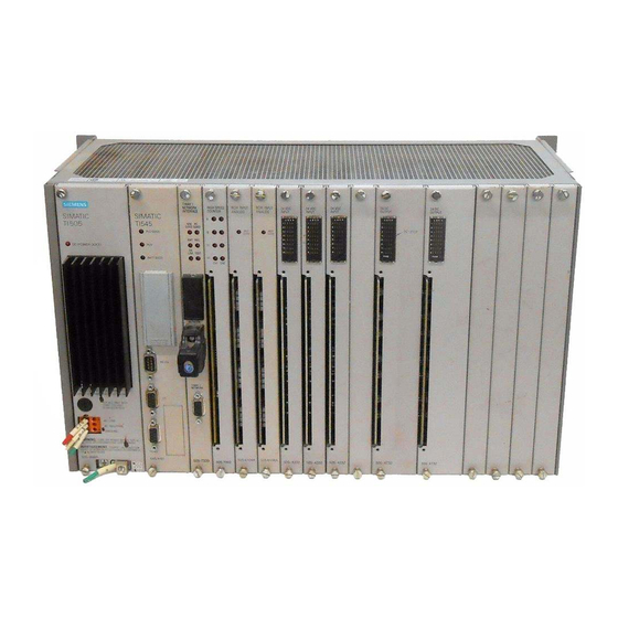
Physical Features of the Module Physical Features The SIMATIC TI505 High Speed Counter Encoder Module (PPX:505–7003) is a single-wide input/output module that communicates with the PLC when installed in a TI505 system. The physical features of the module are shown in Figure 1-1. -
Page 19: Led Indicators
LED Indicators The High Speed Counter Encoder Module (HSCE) provides a total of ten LED indicators on the faceplate. See Figure 1-2. Eight red LEDs indicate the on/off status of outputs 1 through 8. A red LED labeled indicates that the module is powered up MOD GOOD and has not detected any hardware or software failure. -
Page 20: Functional Features Of The Module
Functional Features of the Module Summary of The HSCE module provides a total of six counters and eight outputs, Counters and divided into two channels. Each channel contains the following: Outputs One 24-bit counter: this counter has two pulse inputs, A and B; its primary purpose is to count pulses from an incremental pulse encoder. -
Page 21: Additional Module Features
Additional Module The HSCE module allows you to connect counters internally for cascaded Features counting. The module also provides Immediate I/O operation as well as Interrupt I/O capability (using Task 8 to execute interrupt handling routines). To continue the counting operation in case of a loss of power to the I/O base, you can provide back-up power to the module. - Page 22 Functional Features of the Module (continued) Functional Figure 1-3 presents a functional diagram that summarizes the counters and Diagram outputs provided by the HSCE module. Inputs Outputs User Power Channel 1 + 24 VDC Encoder (or pulse inputs) Output 1 Preset Counter 1 24-Bit...
-
Page 23: Quadrature Modes Of Counting
Quadrature Modes of Counting Quadrature Mode Each 24-bit counter, Counter 1 (Channel 1, inputs A & B) and Counter 4 Overview (Channel 2, inputs A & B) provides Quadrature mode counting. When input A pulses lead input B pulses, the count direction is up. When input B pulses lead input A pulses, the count direction is down. -
Page 24: Quadrature Counting Mode
Quadrature Modes of Counting (continued) 2X Quadrature When set to 2X Quadrature Mode, the module counts both edges of input A Counting Mode pulses, in both count directions. Figure 1-5 shows the relationship between inputs A and B, and the count value that results using 2X quadrature mode. -
Page 25: Non-Quadrature Modes Of Counting
Non-Quadrature Modes of Counting Up/Down Counting When you select the up/down counting mode, two input pulse signals Overview determine the count value. (Refer to Figure 1-7.) With input B high, the count increments on the rising edge of input A. With input A high, the count decrements on the rising edge of input B. -
Page 26: Counting With The 24-Bit Counters
Counting with the 24-Bit Counters Binary Counting, In binary recycle mode, the counter counts up or down on each input pulse. Recycle Mode In the count-up direction, a carry signal is generated when the counter overflows (see note). In the count-down direction, a borrow signal is generated when the count underflows (see note). -
Page 27: Divide-By-N Counting, Non-Recycle Mode
Divide-by-N In divide-by-N non-recycle mode, a preset value is loaded into the counter. Counting, The counter counts up or down on each input pulse. In the count-up Non-Recycle direction, when the counter overflows, it generates a carry signal. In the Mode count-down direction, when the count underflows, it generates a borrow signal. -
Page 28: 24-Bit Counters Quadrature Mode Outputs
24-Bit Counters Quadrature Mode Outputs You can select one of four output options, (see Figure 1-9) for the output signal of each 24-bit counter (Counter 1, Output 1; and Counter 4, Output Outputs in In quadrature counting modes, the internal clocking for the Compare, Carry Quadrature and Borrow pulses produce a pulse width insufficient to drive the outputs. -
Page 29: Figure 1-9 24-Bit Quadrature Mode Outputs
Input A Pulse Input B Pulse X4 Count –5 –4 –3 –2 –1 –1 –2 –3 –4 X2 Count –2 –1 –1 –2 X1 Count –1 –1 Carry Toggle Borrow Toggle Compare Toggle Compare Latch Figure 1-9 24-Bit Quadrature Mode Outputs High Speed Counter Encoder Module User Manual Product Overview 1-13... -
Page 30: 24-Bit Counters Non-Quadrature Mode Outputs
24-Bit Counters Non-Quadrature Mode Outputs Non-quadrature In non-quadrature counting modes, the internal clocking for the Compare, Modes Carry and Borrow pulses are one-half of the input clock width. You can select one of four options for the output signal of each 24-bit counter (Counter 1, Output 1;... -
Page 31: Figure 1-10 24-Bit Counter Output Up Counting
Pulse Input –3 –2 –1 Carry Carry Toggle Rollover Compare Compare Toggle Latch Figure 1-10 24-Bit Counter Output Up Counting Pulse Input –1 –2 Borrow Borrow Toggle Rollover Compare Compare Toggle Latch Figure 1-11 24-Bit Counter Output Down Counting High Speed Counter Encoder Module User Manual Product Overview 1-15... -
Page 32: Outputs In Non-Recycle Mode
24-Bit Counters Non-Quadrature Mode Outputs (continued) Outputs in In non-recycle counting mode, Compare, Carry, and Borrow pulses are not Non-recycle Mode generated. Carry Toggle and Borrow Toggle signals are the cycle completion indicators. At the end of a cycle, additional input count pulses are ignored. One of the following conditions is required to restart the counter: An external INDEX pulse (when WY21.07, or WY27.07, or both are set). -
Page 33: Counting With 16-Bit Counters
Counting with 16-Bit Counters 16–Bit Counter General information for all 16-bit counter modes is presented in following General paragraphs. Figure 1-12 shows that incrementing or decrementing the Description count value occurs on the rising edge of the input clock signal. A valid clock is a high-to-low-to-high transition;... -
Page 34: 16-Bit Counter Modes
Counting with 16-Bit Counters (continued) 16-Bit Counter You can select a 16-bit counter mode by setting the appropriate bits in the Modes Setup Word (WY20). Cascade counting requires that a jumper be configured. You can configure the 16-bit counters to count in one of the following modes: Retriggerable one-shot. -
Page 35: Retriggerable One-Shot
Retriggerable The retriggerable one-shot mode generates an output that is On (high), from One-Shot the first clock after a trigger, and remains On until the preset number of clocks have been counted down to zero. The output is On for the preset number of clocks. -
Page 36: Divide-By-N
Counting with 16-Bit Counters (continued) Divide-by-N Divide-by-N counting generates an output that is On for one clock period every count cycle. The length of the count cycle is the preset number of clocks. The counter counts down from the preset value to 1. The first valid clock pulse, after the gate, loads the preset value (3) and starts decrementing the counter. -
Page 37: Triggered Strobe
Triggered Strobe The triggered strobe mode generates an output that is On for one clock period following the trigger, after the preset number of clocks has been down counted to zero. The output turns On when the preset number of clocks has been counted to zero, or (preset value +1) clocks after the trigger pulse. -
Page 38: Square-Wave Generator Even Preset Value
Counting with 16-Bit Counters (continued) Square-Wave The square-wave generator generates an active output for one-half of the Generator Even preset number of clocks. The length of the down count cycle is the preset Preset Value number of clocks. For an even preset count, the preset is loaded, the output is Off, and the counter starts decrementing by two after the first clock pulse. -
Page 39: Square Wave Generator Odd Preset Value
Square Wave For an odd preset value, the preset – 1 value is loaded, and the counter Generator Odd starts decrementing by two after the first clock pulse. The output turns On Preset Value when the count value is zero and would underflow, however, the counter automatically reloads the preset + 1 value into the counter and starts decrementing by two. - Page 40 Chapter 2 Installing the Module Overview of Installation ............Flow of Tasks .
-
Page 41: Chapter 2 Installing The Module
Overview of Installation Flow of Tasks Figure 2-1 shows the flow of tasks to follow when you install this module. Configure counter mode of operation (See Chapters 3, 4, and 5.) Chapter 4 describes the default configuration of the module. Insert module into I/O base. -
Page 42: Inserting The Module Into The Base
Inserting the Module into the Base WARNING To minimize potential shock, turn off power to the I/O base and to any modules installed in the base before inserting or removing a module, or installing a terminal block. Failure to do so may result in potential injury to personnel or damage to equipment. -
Page 43: Wiring The Module
Wiring the Module I/O Connections You should wire all of your input and output signals to the HSCE module removable terminal block. Table 2-1 lists the I/O connections together with a cross-reference listing of the terminals in numeric order Table 2-1 I/O Connections Terminal Connection Terminal... -
Page 44: Figure 2-3 Terminal Blocks And I/O Connections
PPX:2587705–8010 PPX:2587705–8011 Side-accessible Front-accessible Back-up Power +12V 12 Volts DC Back-up Power RTN Class 2 Power Supply Ch1 A+ Ch1 A– Ch1 B+ Ch1 B– Ch1 C+ Ch1 C– Ch1 D+ Ch1 D– Ch1 INDEX+ Ch1 INDEX– Ch1 RESET+ Ch1 RESET– Ch1 INHIBIT+ Ch1 INHIBIT–... -
Page 45: Wiring The Terminal Block
Wiring the Module (continued) Wiring the Terminal You wire the HSCE module by wiring the user power supply and input and Block output signals. All connections are made at the terminal block. To wire the terminal block, follow the procedure below. Turn the terminal block, with the screw-heads facing you, until the series of terminals is at the top and the series is at the bottom. -
Page 46: Wiring The Inputs
Wiring the Inputs Input connections to the module can be electronic output drive devices or mechanical switches. Figure 2-4 shows an example of wiring electronic encoder outputs to the input terminals of the module for a non-inverted signal. Module Encoder Constant current load A–... -
Page 47: Figure 2-6 Differential Line Drive
Wiring the Module (continued) Figure 2-6 shows an example of wiring differential line drive inputs. Module Encoder Input Constant current load A– Input Figure 2-6 Differential Line Drive Table 2-2 Features of Electronic Drives Open Collector or Single-Ended Differential Drives 5 to 24 V Normally 5 V Source or sink... -
Page 48: Figure 2-7 Mechanical Switches
Figure 2-7 shows an example of wiring mechanical switch inputs. (Note that with mechanical switches, the contacts can “bounce” when switched.) Module Constant current load A– Module Constant current load A– Figure 2-7 Mechanical Switches High Speed Counter Encoder Module User Manual Installing the Module... -
Page 49: Wiring The Outputs
Wiring the Module (continued) Wiring the Outputs Figure 2-8 shows an example of output wiring. +24 V To 7 other outputs Power supply fuse: 100 mA + Total Load Current* Output Drive Output fuse: Rated load current* Load Inductive Load Protection *External fuses provided by user must conform to accepted wiring practives required by the installation. -
Page 50: Connecting The Terminal Block
Connecting the To connect the terminal block to the module, follow these steps. (See Terminal Block Figure 2-9.) Align the terminal block with the edge card connector on the bezel. Press firmly at both ends of the terminal block until it is seated. Tighten the screws at the top and bottom. -
Page 51: Powering Up The Base
Powering Up the Base Supplying Power to Refer to the system manual for your controller for information on installing the I/O Base and wiring the power supply for your I/O base. Follow all installation guidelines and safety considerations described in your system manual before powering up the system. -
Page 52: Configuring I/O Addresses In The Controller
To confirm the I/O map and verify controller-to-module communications, connect a PLC programming device (e.g., TISOFT ) to the controller. (For information on configuring the I/O, refer to your SIMATIC TI505 TISOFT2 User Manual.) Power up the base and follow these steps: Ensure that the MOD GOOD indicator is on and the error bit is clear. - Page 53 Chapter 3 Understanding Module Operation Module I/O Map ..............Data Formats .
-
Page 54: Module I/O Map
Module I/O Map PLC-to-Module The HSCE module communicates with the PLC using word inputs and word Communications outputs. The PLC reads current count values, holding registers, and module Overview status bits from word inputs. Word outputs contain user-defined counter configuration setups and preset values. I/O Word Table 3-1 lists the definitions for the word inputs (WX) and the word Definitions... -
Page 55: I/O Words Grouped By Counter
I/O Words Grouped Figure 3-1 shows how the WX and WY words are grouped by counter to help by Counter you configure each counter in the HSCE module. Channel 1 Counter 1 — 24-Bit Current Count: WX1 & WX2 Holding Register #1: WX9 & WX10 Holding Register #2: WX11 &... -
Page 56: Data Formats
Data Formats Current Count and The current count value for each 24-bit counter is contained in two word Holding Register inputs (for example, WX1 and WX2). Count Value Formats The count range is from 0 to 16,777,215 in unipolar mode. The count range is from +8,388,607 to –8,388,608 in bipolar mode. -
Page 57: 24-Bit Preset And Configuration Formats
24-Bit Preset and Each 24-bit counter has two preset values to control two outputs, as listed in Configuration Table 3-1 and shown in Figure 3-1. The 24-bit unipolar value for each preset Formats is contained in the lower byte of the most significant word and both bytes of the least significant word, as shown by the shaded areas in Table 3-3. -
Page 58: Reading Module Status
Reading Module Status Module Status The PLC reads the module status bits in word inputs WX17 and WX18. The Words on/off status of the eight outputs, count direction, interrupts, module mode, error conditions, and other indicators are contained in these words, listed in Table 3-6. -
Page 59: Wx18.01, Run Mode
TASK 8, from the PLC when an output changes state. The outputs that can cause an interrupt are set in bits WY19.09 through 16. Refer to the SIMATIC TI505 Programming Reference Manual (PPX:505–8104–4 or later) for interrupt information. -
Page 60: Configuring Program Mode Setup Words
Configuring Program Mode Setup Words Setup Words: You can use WY19 and WY20 to choose specific counter input or output Program Mode options in Program Mode, as listed in Table 3-8. (The format is shown in Table 3-7.) Table 3-7 Module Setup Words Word MSByte LSByte... -
Page 61: Program Mode Definitions
The following paragraphs provide expanded definitions for setup words WY19 and WY20 in Program mode. Program Mode At the start of Program Mode, all counters are inhibited and reset. When Definitions programming is complete, WX18.02 is set and WY19.01 through WY19.08 function normally. -
Page 62: Configuring Run Mode Setup Words
Configuring Run Mode Setup Words Setup Words: Table 3-9 shows that you can use WY19 and WY20 to choose specific counter Run Mode input or output options that are programmable when the module is in Run Mode. These options can be selected only with bit WY20.01 cleared, which puts the module in Run Mode. -
Page 63: Reset Bits: Wy19.03, 04 And Wy19.07
The following options can only be selected with bit WY20.01 cleared, which puts the module in Run Mode. Inhibit Bits: WY19.01 While the inhibit bit is set, it inhibits (pauses) the counting of Counter 1 and WY19.05 and bit WY19.05 inhibits the counting of Counter 4. Reset Bits: WY19.02 When set, Reset Counter 1 (WY19.02) and Counter 4 (WY19.06) clears the and WY19.06... -
Page 64: Setting Preset Values And Programming Options For Channel 1
Setting Preset Values and Programming Options for Channel 1 Channel 1, The lower byte of WY21 and all of WY22 contain the Preset 1 24-bit integer 24-Bit Counter 1, value. Use the upper byte of WY21 to configure programming values. Preset 1 Together, the preset value and the programming values determine the count method and how Output 1 functions when count and preset are equal, or... -
Page 65: Channel 1, 24-Bit Counter 1, Preset
Channel 1, The lower byte of WY23 and all of WY24 contain the Preset 2 24-bit integer 24-Bit Counter 1, value. Use the upper byte of WY23 to configure programming values. Preset 2 Together, the preset value and the programming values determine the count method and how Outputs 1 and 2 function when the count and preset are equal, or the count value is less than or greater than the counter preset. -
Page 66: Channel 1, 16-Bit Counter Presets
Setting Preset Values and Programming Options for Channel 1 (continued) Channel 1, 16-Bit Table 3-14 and Table 3-15 shows the formats for the preset values Counter Presets (0 – 65535) for Counters 2 and 3. Table 3-14 Channel 1, 16-Bit Counter 2: Preset 3 Value Word MSByte LSByte... -
Page 67: Channel 2, 24-Bit Counter 4, Preset
Setting Preset Values and Programming Options for Channel 2 Channel 2, The lower byte of WY27 and all of WY28 contain the 24-bit integer Preset 5 24-Bit Counter 4, value. Use the upper byte of WY27 to configure programming values. Preset 5 Together, the preset value and the programmed values determine the count method and how count Output 5 functions when count and preset are equal,... -
Page 68: Channel 2, 24-Bit Counter 4, Preset
Setting Preset Values and Programming Options for Channel 2 (continued) Channel 2, The lower byte of WY29 and all of WY30 contain the 24-bit integer Preset 6 24-Bit Counter 4, value. Use the upper byte of WY29 to configure programming values. Preset 6 Together, the preset value and the programming values determine the count method and how Outputs 5 and 6 function when the count and preset are... -
Page 69: Channel 2, 16-Bit Counter Presets
Channel 2, 16-Bit Table 3-20 and Table 3-21 shows the formats for the preset values Counter Presets (0 – 65535) for Counters 5 and 6. Table 3-20 Channel 2, 16-Bit Counter 5: Preset 7 Value Word MSByte LSByte WY31 Table 3-21 Channel 2, 16-Bit Counter 6: Preset 8 Value Word MSByte LSByte... - Page 70 Chapter 4 Using the Default Configurations Default Hardware Modes ............Factory Jumper Settings .
-
Page 71: Default Hardware Modes
Default Hardware Modes Factory Jumper This chapter describes the default modes of operation selected by factory Settings installed jumpers. The jumpers are set at the factory to specific defaults. Using these default settings (see Figure 4-1) and a minimal amount of software programming, you can operate your High Speed Counter Encoder module immediately after installing it in the I/O base. -
Page 72: 24-Bit Counter Inputs
24-Bit Counter Figure 4-1 shows that the default inputs for each 24-bit counter (1 and 4) Inputs are the A and B input pulse lines. The default jumper settings provide input connections for all counting modes: non-quadrature up/down counting, non-quadrature direction counting, and quadrature mode. NOTE: To set the counter’s mode, you have to set specific bits in the software as described in Chapter 5. -
Page 73: Default Software Modes
Default Software Modes Programming You program counter modes by setting specific bits in the corresponding WY Optional Modes words. If bits 01 through 08 of the preset word are all zeroes, by default or programming, the module operates in the modes defined in Table 4-1. Programming of optional modes is described in Chapter 5. -
Page 74: Basic Programming Steps
Basic Programming Steps To program the High Speed Counter Encoder module and place it in Run Mode, perform the following steps: Writing the Presets In your RLL program, write the preset values to the words that correspond to the counters you are setting up. A preset value of all zeros is valid. As described in Chapter 3, preset values for each counter are stored in the WY words listed in Table 4-2. -
Page 75: Overview
Chapter 5 Optional Configurations Overview ............... Required Tasks for Setting Up Optional Configurations . - Page 76 Overview Required Tasks for Instead of the default configurations, you can set up other counting and Setting Up Optional connection configurations by changing hardware jumpers and setting Configurations software bits in the module setup and preset words. Default jumpers connect various signals and registers together; however, to function correctly, the module must also be configured in software through the module setup word and the high byte of preset words.
-
Page 77: Figure 5-1 Jumper Locations
Configuration Jumpers An overview of the jumper locations and functions is shown in Figure 5-1. Shaded boxes are the default jumper positions. A jumper configuration work sheet is provided in Appendix B for you to record your jumper settings. Counter Inputs: Counter: Input A pulse —... -
Page 78: Figure 5-2 Configuration Map
Configuration Map Figure 5-2 presents an overview of the jumper selection and programming tasks necessary to configure the module. Although the tasks are presented serially, you may execute them randomly by choosing those that apply to your application. Basic 24-Bit Counter Select Set up Select... - Page 79 24-Bit Counter Set up Set up Recycle/ 16-Bit Counter WY21.06 Non-Recycle Use Holding Mode Jumper for Input positions 24-Bit Counter Set up Set up 16-Bit Counter 6 Gate WY23.01 thru Preset 2 16-Bit Counter 5 Compare Mode Clock 16-Bit Counter 3 Gate 16-Bit Counter 2 16-Bit Counter 2...
-
Page 80: Figure 5-3 Basic Configuration Jumpers
Basic Configuration Options Several jumper options are independent of the options selected by other jumpers or software settings. These basic options include the following: Input filtering Disabling outputs under Module Failure or PLC Output Disable conditions Output polarity Figure 5-3 shows jumper locations for the basic options. Jumpers are shown in their default positions. -
Page 81: Table 5-1 Input Filtering Jumper Options
Input Filtering Two jumpers, one for Channel 1 and one for Channel 2, select the minimum Options input pulse width detected by the counter. By selecting the appropriate filtering jumper, you can prevent narrower input signals or noise from being counted by the counter. - Page 82 24-Bit Counter Input Jumper Selection Figure 5-4 shows the jumpers that select input signals for the 24-bit counter. Table 5-2 defines the input signal names referred to in following paragraphs. After you select the jumpers, you must program the setup words and preset words.
-
Page 83: Counter 2 [5] Or Counter 3 [6] Jumpers
NOTE: Select one of the following four A input jumper positions for both Counter 1 and Counter 4 24-bit counters: (Input A, 1 s, Counter 2 [5], or Counter 3 [6]. Input A Jumper The Input A jumper connects the input A terminal to the counter Input A. Input A jumper is the default setting for the 24-bit counter. -
Page 84: Control And Output Jumper Selections
Control and Output Jumper Selections Figure 5-5 shows jumper locations that select signals for the 24-bit counters. After you select the jumpers, you must program the setup words and preset words to enable the selected functions. Jumpers are shown in their default positions. -
Page 85: Latch Or Reset-And-Go Jumper
Latch or In the Latch (default) position (left), this jumper selects the INDEX signal Reset-and-Go to load the counter’s value into the output holding register. Set WY21.07 Jumper [Channel 1] and WY27.07 [Channel 2] to enable the Latch function. With this jumper in the Reset-and-Go position (right), the INDEX signal loads the counter’s value into the output holding register, and then clears the counter to zero. -
Page 86: 24-Bit Counter Software Setup Options
24-Bit Counter Software Setup Options After you configure the hardware jumpers, select the associated bits in both the preset and setup words to enable the functions. There are four preset words (WY21 through WY24) and two setup words (WY19 and WY20) associated with the 24-bit counter. -
Page 87: Table 5-3 Channel 1, 24-Bit Counter: Preset 1 Value
Table 5-3 Channel 1, 24-Bit Counter: Preset 1 Value Word MSByte LSByte WY21 WY22 Table 5-4 shows the counting options bit definitions. Shaded areas represent the default modes (all bits are zero). Table 5-4 Channel 1, 24-Bit Counter: WY21 Programming Bit Values Bit Position Description Mode... -
Page 88: Table 5-5 Channel 1, 24-Bit Counter: Preset 2
24-Bit Counter Software Setup Options (continued) Table 5-5 and Table 5-6 show that the MSByte of WY23 programs the preset compare functions of the 24-bit counter. The LSByte of WY23 and all of WY24, shown shaded in the table, contain the 24-bit integer preset 2 value. Table 5-5 Channel 1, 24-Bit Counter: Preset 2 Word MSByte... -
Page 89: Table 5-7 Bit Definitions For The Run Mode Setup Words
Table 5-8 and Table 5-7 show that module setup words WY19 and WY20 program additional functions of the 24-bit counter. The module setup words have two modes: Run and Program. In Run mode, the definitions in Table 5-7 apply; in Program, the definitions in Table 5-8 apply. -
Page 90: 16-Bit Counter Options
16-Bit Counter Options Five two-position jumpers enable you to select a clock input and control signal for each 16-bit counter. See Figure 5-7. Jumpers are shown in their default positions. Counter 2 Counter 3 Jumper Holding Jumper Holding 1 µs clock 1 µs clock A Input Pulse A Input Pulse... -
Page 91: Holding Position
NOTE: Select two input jumpers from the following list. Select one jumper to clock the counter and one jumper (or none) to gate the counter. Holding Position The holding position simply stores the jumper until needed. 1 s Jumper The 1 s jumper selects a 1 s internal signal to clock the counter; the gate position is not applicable for this jumper. -
Page 92: 16-Bit Counter Software Setup Options
16-Bit Counter Software Setup Options After you configure the hardware jumpers, select the associated bits in the setup words to enable the functions and select the mode. There are two setup words and two preset words associated with the 16-bit counters. In the interest of simplicity, only the parts of these words pertinent to the 16-bit counter are shown. -
Page 93: Figure 5-8 16-Bit Counter Mode Setup
Table 5-10 Bit Definitions for the Program Mode Setup Words Word.Bit Description of Bit Functions for PROGRAM Mode WY19.01 At start of Program Mode, all of the counters are inhibited and reset. through WY19.08 WY20.07 Channel 1, 16-bit Counters 2 and 3: Down (0) or Up (1) counting WY20.08 Channel 2, 16-bit Counters 5 and 6: Down (0) or Up (1) counting WY20.09... -
Page 94: Basic Programming Steps
5.10 Basic Programming Steps To program the High Speed Counter module and place it in Run Mode, perform the procedure at the beginning of each paragraph heading. Additional paragraphs provide descriptions of status bits and other actions that occur as you program the module. NOTE: At power-up, the module runs an internal software diagnostic. -
Page 95: Setting The Program Bit
Setting the To program the HSCE module, set bit WY20.01 (see shaded bit in Program Bit Table 5-13). Set bit WY20.01 by writing the programming values to WY19 and WY20 word locations. After you set the program bit (WY20.01), the indicator is off. -
Page 96: Appendix A Applications
Appendix A Applications Using Counters 1 and 4 ............Using Gated Counting . -
Page 97: Using Gated Counting
Using Counters 1 and 4 In the following counting modes, the 24-bit counter counts up or down on each input pulse received as long as INHIBIT and RESET are low. Using Gated In gated counting, the current count words are continuously updated by the Counting module and read by the PLC on each scan. -
Page 98: Using Time Sampled Rate Counting
Using Time In time sampled rate counting, the counter counts the number of input Sampled Rate pulses during a given period. You select the sample period (1 ms, 10 ms, Counting 100 ms, or 1 second) by setting the appropriate bits in the preset word and by setting the control jumpers to [Internal Period] and [Reset-and-go]. -
Page 99: Using Counters 2, 3, 5, And 6
Using Counters 2, 3, 5, and 6 Using Binary Up or The 16-bit counters can be configured as binary counters. The count value Down Counting wraps about the count value of zero and continues counting in the upward or downward direction. You select the count direction in bit WY20.07 for counters 2 and 3, or WY20.08 for counters 5 and 6. -
Page 100: Using Divide-By-N Mode
Using Divide-by-N Configure the counter for Divide-by-N mode as follows: Mode Preset: Divide-by-N counting sets the count value to zero on the first valid clock pulse. The clock increments the count value until it is 65535. At that time the output turns On and remains On for one clock period. The preset (0) is loaded into the counter, counting continues, and the output pulses each cycle. -
Page 101: Cascade Counting Applications
Cascade Counting Applications 32-Bit Cascade The 32-bit cascade counting mode cascades the output of one channel’s Counting 16-bit counter (3 or 6), in Divide-by-N mode, into the clock input of the other 16-bit counter (2 or 5) of the same channel. When both channel counters, 2 and 3 or 5 and 6, are configured in Up Counting, Divide-by-N mode, the module assumes 32-bit cascaded counting has been configured and converts the count value by adding 1. -
Page 102: Prescale Counting Applications
Prescale Counting Applications 16-Bit Prescale The 16-bit prescale 16-bit counting mode cascades the output of one 16-bit 16-Bit Counting counter, in Divide-by-N mode, into the same channel’s other 16-bit counter. This counting mode functions the same as 32-bit cascade counting described in Section A.3, Cascade Counting Operations;... -
Page 103: 16-Bit Prescale 24-Bit Counting
Prescale Counting Applications (continued) 16-Bit Prescale The 16-bit prescale 24-bit counting mode cascades the output of one 16-bit 24-Bit Counting counter, in Divide-by-N mode, into the A input of the same channel’s 24-bit counter. The B input jumper is set for Up Count Only. By using the repetitive nature of Divide-by-N mode, the output of the 16-bit counter pulses the rollover signal, at every count of 1, into clock input A of the 24-bit counter. -
Page 104: Led Status And Error Code Descriptions
Appendix B Troubleshooting LED Status and Error Code Descriptions ......... . . Troubleshooting . -
Page 105: Table B-1 Led Indicator Status Chart
LED Status and Error Code Descriptions Table B-1 presents the status indications of the module’s LEDs. Table B-1 LED Indicator Status Chart MOD GOOD Description (Red) (Green) Off or On No base power, or fatal error exists Normal run condition Module not in Run mode Fast blink Module not programmed... -
Page 106: Troubleshooting
Troubleshooting Table B-3 presents basic troubleshooting suggestions for the module. Table B-3 Troubleshooting Suggestions Symptom Probable Cause Corrective Action No LEDs on No power to board Re-seat board Check for bent pins on board connector Check your base power supply; user power supply Module has failed Return module for repair self-diagnostics... -
Page 107: Terminal Block Worksheets
Terminal Block Worksheets Terminal block worksheets are provided in Figure B-2 and Figure B-4 for you to record the wiring for this module. Side-accessible Terminal Block (PPX:2587705–8010) Back-up Power +12V Back-up Power RTN Ch1 A+ Ch1 A– Ch1 B+ Ch1 B– Ch1 C+ Ch1 C–... -
Page 108: Figure B-2 Terminal Block Worksheet
Figure B-2 Terminal Block Worksheet High Speed Counter Encoder Module User Manual Troubleshooting... -
Page 109: Figure B-3 Typical Front-Accessible Terminal Block
Terminal Block Worksheets (continued) Front-accessible Terminal Block (PPX:2587705–8011) Back-up Power +12V Back-up Power RTN Ch1 A+ Ch1 A– Ch1 B+ Ch1 B– Ch1 C+ Ch1 C– Ch1 D+ Ch1 D– Ch1 INDEX+ Ch1 INDEX– Ch1 RESET+ Ch1 RESET– Ch1 INHIBIT+ Ch1 INHIBIT–... -
Page 110: Figure B-4 Terminal Block Worksheet
Figure B-4 Terminal Block Worksheet High Speed Counter Encoder Module User Manual Troubleshooting... -
Page 111: Jumpers Worksheet
Jumpers Worksheet Figure B-5 provides a jumper configuration worksheet for you to record the jumper configurations that you select. Counter Inputs: Counter: Input A pulse — Jumper holding position 1 s internal 1 s internal 16-Bit Counters 2, 3, 5, 6 Counter 2 output A in A input... -
Page 112: Appendix C Specifications
Appendix C Specifications Environmental Specifications ........... . Input Specifications . - Page 113 Environmental Specifications Table C-1 Physical and Environmental Specifications Minimum torque for bezel screws and connector screws 2.6 in-lb (0.3 N-m) Maximum torque for bezel screws and connector screws 5.2 in-lb (0.6 N-m) Input signal wiring Shielded, twisted pair cable (12–26 AWG or 0.16–3.2 mm , stranded or solid) Spade lug for use with connector 2587705–8010 Amp part number 321462...
-
Page 114: Input Voltage And Current Specifications
Input Specifications Input Voltage The HSCE Module responds to input signals according to the specifications and Current listed in Table C-2 and shown in Figure C-1. Specifications Table C-2 Input Voltage and Current Specifications On Voltage 4 to 28 VDC maximum On Current 7 to 13 mA Off Voltage... -
Page 115: Input Filter Characteristics
Input Specifications (continued) Input Filter The input filter eliminates glitches or noise in the incoming signal from Characteristics being counted. The input signal must have a high and low pulse width greater than the specified filter period values listed below for proper operation. -
Page 116: Minimum Pulse Width For Quadrature Mode
Minimum Pulse The input filter has a clock that synchronizes the input pulse train. The Width for clock periods for each filter are listed below. Quadrature Mode Filter Frequency 1/2 Filter Period 100 kHz filter: 2 microseconds 25 kHz filter: 8 microseconds 6.25 kHz filter: 32 microseconds... - Page 117 Input Specifications (continued) If the edges are not separated by the time required for the filter period, then the counting may be off. This type of error can be determined by inputting both an up-count and down-count Quadrature pulse train at the rated frequency.
-
Page 118: Output Specifications
Output Specifications Output Voltage The HSCE Module output circuits meet the specifications listed in and Current Table C-3. Specifications Table C-3 Output Specifications User Voltage 28.8 VDC maximum Voltage Drop (power supply to 1.4 volts maximum at 500 mA output terminal) Leakage Current (Off state) Less than 10 microamps Output Current ratings... -
Page 119: Module Response Times
Output Specifications (continued) Module Response The module software cycle time is less than 1 millisecond. The typical Times response times of input to output signals are listed in Table C-4. Table C-4 Module Response Times Counter 1 to output 1 Less than 10 microseconds Counter 1, Preset 2 to output 1 Less than 1 millisecond... - Page 120 Index Configuring I/O memory, 2-13 Connecting terminal block, 2-11 Addressing I/O, 3-2 Control signal, jumpers, 5-10–5-11 Agency approvals, xiv Conventions, in this manual, xiv Assistance, telephoning for, xiv Count value format, 3-4 Avoiding noise, 2-6 Counter control signals, 4-3 inputs, 4-3 Counting modes divide-by-N, 1-20 Back-up power, wiring connections, 2-4...
- Page 121 Input filters, 5-7, C-5 signal filtering default setting, 4-3 Features specifications, C-3–C-6 16-bit counters, 1-4 wiring, 2-7, 2-8 24-bit counters, 1-4 Input signals functional, 1-4 definitions, 5-8 physical, 1-2 for 16-bit counters, 5-16–5-17 Filter options, 5-7 for 24-bit counters, jumpers, 5-8–5-9 Filtering input signals, default setting, 4-3 Inputs filters, 5-7 Frequency counting, A-3...
- Page 122 Output control jumpers, 5-10–5-11 specifications, C-7 Latch, 4-3 wiring, 2-10 jumper, 5-11 outputs, 1-12 Output polarity default settings, 4-3 Latch/reset-and-go jumper, 5-11 jumpers, 5-7 LED indicators, 1-3, 2-12, B-2 Outputs disabled flag, 3-7 LEDs, status at power-up, 2-12 Outputs, of 16-bit counters Line driver, differential, 2-8 forced on by PLC, 1-17, A-6, A-7, A-8 in divide-by-N mode, 1-20...
- Page 123 Software, optional features, 4-4 Software compatibility, xiii, 1-5 Quadrature modes Software setup options 1X quadrature counting, 1-7 16-bit counters, 5-18 2X quadrature counting, 1-8 24-bit counters, 5-12–5-15 4X quadrature counting, 1-8 Specifications minimum input pulse width, C-5 electrical, C-3–C-6 environmental, C-2 input, C-3–C-6 output, C-7 Rate, time sampled counting, A-3...
- Page 124 Underflow, 1-10 Wiring Unipolar mode, 1-10, 3-4 inputs, 2-7, 2-8 outputs, 2-10 Up count only, jumper, 5-9 terminal block, 2-6 Up/down counting, 1-9 the module, 2-4–2-11 Up/Down counting in Word I/O definitions, 3-2 Divide-by-N mode, A-5 Retriggerable One-shot mode, A-4 Worksheet Triggered Strobe mode, A-5 jumpers, B-8...
- Page 126 Would you be interested in giving us more detailed comments about our manuals? Yes! Please send me a questionnaire. No. Thanks anyway. Your Name: Title: Telephone Number: Company Name: Company Address: Manual Name: SIMATIC TI505 High Speed Counter Encoder User Manual Edition: Original Manual Assembly Number: 2586546–0092 Date: 05/94 Order Number: PPX:505–8127–1...
- Page 127 UNITED STATES BUSINESS REPLY MAIL PERMIT NO.3 FIRST CLASS JOHNSON CITY, TN POSTAGE WILL BE PAID BY ADDRESSEE ATTN: Technical Communications M/S 3519 SIEMENS INDUSTRIAL AUTOMATION INC. 3000 BILL GARLAND RD P O BOX 1255 JOHNSON CITY TN 37605–1255 FOLD...
Need help?
Do you have a question about the SIMATIC TI505 and is the answer not in the manual?
Questions and answers