
Related Manuals for Siemens SIMATIC TI525


Summary of Contents for Siemens SIMATIC TI525
- Page 1 (217) 352-9330 | Click HERE Find the Siemens / Texas Instruments 500-5037A at our website:...
- Page 2 Artisan Technology Group - Quality Instrumentation ... Guaranteed | (888) 88-SOURCE | www.artisantg.com...
- Page 3 SIMATIC TI525/TI535 Hardware and Installation User Manual Order Number: PPX:505–8103–3 Manual Assembly Number: 2586546–0052 Third Edition Artisan Scientific - Quality Instrumentation ... Guaranteed | (888) 88-SOURCE | www.artisan-scientific.com Artisan Technology Group - Quality Instrumentation ... Guaranteed | (888) 88-SOURCE | www.artisantg.com...
- Page 4 Technical data is subject to change. contents is not permitted without express consent of Siemens Industrial Automation, Inc. All rights, including rights We check the contents of every manual for accuracy at the created by patent grant or registration of a utility model or time it is approved for printing;...
- Page 5 MANUAL PUBLICATION HISTORY SIMATIC TI525/TI535 Hardware and Installation Manual Order Manual Number: PPX:505–8103–3 Refer to this history in all correspondence and/or discussion about this manual. Event Date Description Original Issue 09/88 Original Issue (2586652–0001) Second Edition 11/90 Second Edition (2586652–0002)
- Page 6 LIST OF EFFECTIVE PAGES Pages Description Pages Description Cover/Copyright Third Edition History/Effective Pages Third Edition iii — viii Third Edition Preface ix–x Third Edition 1-1 — 1-10 Third Edition 2-1 — 2-7 Third Edition 3-1 — 3-32 Third Edition 4-1 — 4-13 Third Edition 5-1 —...
-
Page 7: Table Of Contents
Contents Preface Chapter 1 Series 505 System Overview Introduction ..............Features Of The TI525 And TI535 . - Page 8 3.5.2 Model TI535 Battery Installation ........3-18 Installing System Components .
- Page 9 Grounding ..............B.2.1 Single Point Grounding .
- Page 10 List of Figures 1-1 TI525 and TI535 Controllers ............1-2 Functional Relationship of Series 505 Components .
- Page 11 List of Tables 1-1 Model Differences ..............1-2 TI525/TI535 Instruction Set .
-
Page 12: Preface
This manual gives detailed instructions for the installation and operation of the Series 505 family of programmable logic controllers (PLCs). Both the SIMATIC TI525 and the SIMATIC TI535 PLCs and their support equipment are discussed. The topics are listed below by chapter. - Page 13 PREFACE REFERENCES Consult the manuals listed below for further information on installing, programming, and troubleshooting your Series 505 hardware. SIMATIC TI505 Programming Reference Manual (PPX:505–8104–3) TIWAY Systems Manual (TIWAY–8101) CVU1000 & CVU10000 User Reference Manual (PPX:CVU10–8101–2) The I/O module user manuals that are appropriate for your system. The user manuals for your release of TISOFT .
-
Page 14: Series 505 System Overview
CHAPTER 1 SERIES 505 SYSTEM OVERVIEW INTRODUCTION The TI525/TI535 Programmable Controllers (PLCs) and their support equipment are computer-controlled systems that are capable of managing the operation of other systems. These PLCs execute the same functions as relays, static control, or card logic control systems. They can detect the change in state of input signals from such devices as pushbuttons, limit switches, and sensors. -
Page 15: Ti525 And Ti535 Controllers
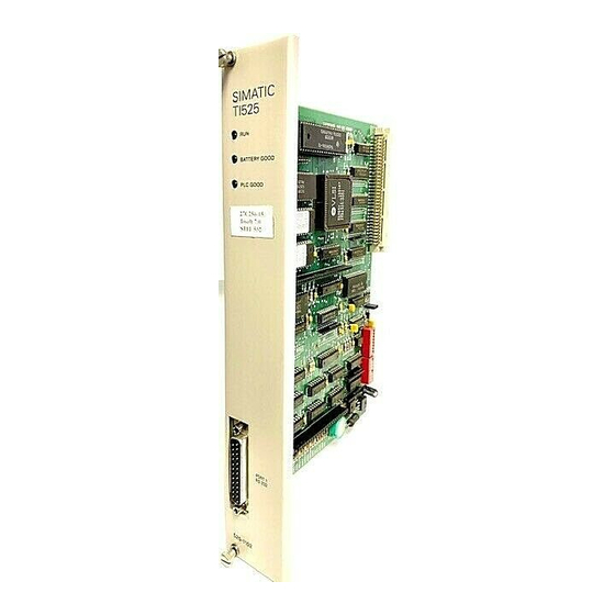
FEATURES SIMATIC SIMATIC TI525 TI535 BATTERY GOOD BATT GOOD P/C GOOD P/C GOOD PORT RS422 PORT PORT RS232 RS232 525–1102 535–1212 Figure 1-1 TI525 and TI535 Controllers The Series 505 product line is designed for use in small to medium applications such as discrete, word, and analog control. - Page 16 FEATURES You may use a DEC Computer to develop an RLL program that can be transferred to a TI525/TI535 PLC with a VPU. You can provide communication between devices through the TIWAY industrial local area network. See the references listed in the Preface of this manual for information on these systems.
-
Page 17: Functional Relationship Of Series 505 Components
FEATURES IBM PC/XT with TISOFT DEC VAX VPU–200 Handheld Intelligent Terminal Programming Unit TI525* Series 505 I/O TI525 Series 505 I/O 4, 8, and 16 slots 4, 8, and 16 slots TI535 TI535 Local PPX: 505– 6830 Distributed Series 505 I/O 4, 8, and 16 slots PPX: 505–... - Page 18 FEATURES The power supply provides up to 55 watts at +5 VDC and 3.75 watts at –5 VDC for use by the PLC, the base controllers, and the I/O modules. The PPX:505–6660 power supply operates at either 110 V or 220 VAC on user-supplied power.
-
Page 19: Features Of The Ti525 And Ti535
FEATURES FEATURES OF THE TI525 AND TI535 Two models of the TI525 and one of the TI535 are currently available. Differences between these models are given in Table 1-1. The TI525/TI535 RLL instruction set is listed in Table 1-2. Table 1-1 Model Differences Features PLC Model PPX:525... -
Page 20: Ti525/Ti535 Instruction Set
FEATURES Table 1-2 TI525/TI535 Instruction Set Program Control Instructions Jump (JMP) End, Conditional (ENDC) Label (LBL) End, Unconditional (END) Master Control Relay (MCR) Skip (SKP) Math Instructions Add (ADD) Divide (DIV) Subtract (SUB) Multiply (MULT) Compare (CMP) Square Root (SQRT) Bit Instructions Bit Clear (BITC) Bit Set (BITS) -
Page 21: Program Software
FEATURES 1.2.1 Program Software The TI525/TI535 PLCs are programmed in standard relay ladder logic, and TISOFT programming software provides a means of entering, debugging, and documenting your RLL program. TISOFT is menu-driven, provides both RLL and advanced program special functions language, and permits you to add comments to instructions. -
Page 22: Communication Ports
FEATURES 1.2.3 Communication Ports Each TI525/TI535 PLC has a 25-pin RS-232-C/RS-423 compatible port configured as Data Terminal Equipment (DTE). This port may be used for communicating with programming equipment such as the Timer/Counter Access Module (TCAM), the VPU, a CVU, or a modem up to 50 feet (15 m) away. An RS-422 compatible port is also available on the PPX:535–1212. -
Page 23: Ladder Memory Protection
FEATURES 1.2.5 Ladder Memory Protection A memory protection dipswitch provides protection for the RLL program. When the switch is in the ON position, the program cannot be changed by a programming device that is connected to the PLC through one of the communication ports. -
Page 24: Pre-Installation Planning
CHAPTER 2 PRE-INSTALLATION PLANNING This chapter presents recommended installation practices and procedures. Since no two applications are identical, these recommendations are guidelines. INTRODUCTION Preparing the site for installation of your TI525/TI535 PLC consists of the following: Defining the control requirements Determining the number of PLCs needed Determining the panel and grounding layout You should define the control requirements in terms of the number and type of... - Page 25 PRE-INSTALLATION If you, or your company, use any programmable controllers with equipment which requires an operator or attendant, you should be aware that this potential safety hazard exists and take appropriate precautions. Although the specific design steps depend your particular application, the following precautions generally apply to installation of solid-state programmable control devices.
- Page 26 PRE-INSTALLATION ICS 3–304.81 Safety Recommendations: Consideration should be given to the use of an emergency stop function which is independent of the programmable controller. Where the operator is exposed to the machinery, such as in loading or unloading a machine tool, or where the machine cycles automatically, consideration should be given to the use of an electromechanical override or other redundant means, independent of the programmable controller, for starting and interrupting the cycle.
-
Page 27: Safety Considerations
PRE-INSTALLATION SAFETY CONSIDERATIONS Pre-installation planning and site preparation must include consideration of hazards to personnel during a system failure. The equipment connected to the TI525/TI535 PLC should include interlocks and safety switches to prevent operation during a system failure. Although the specific steps depend on the application, the general precautions include the following: Provide a means for disconnecting power—independent of the PLC—from the output loads when a machine is not operating, or when... -
Page 28: Emergency Stop Switch
PRE-INSTALLATION Provide a means for removing power from the output if an emergency condition occurs with the machine during operation. Do this by disconnecting output power with a non-semiconductor switch or hard-wired relay contact, not through the programmable control system. This type of switch is shown in Figure 2-2. Reset Emergency Guard... -
Page 29: Enclosure Selection
PRE-INSTALLATION Bypass the programmable control system with an external JOG or INCH switch during machine loading or setup operations. See Figure 2-3. Switch or contact closed in the jog or inch mode User-supplied critical loads which could cause injury Switch or contact open in the JOG or INCH mode Output... -
Page 30: Grounding And Wiring The Equipment
PRE-INSTALLATION Mount the TI525/TI535 components in a dustproof and drip tight enclosure such as the NEMA Type 12 enclosure. The enclosure must provide a minimum depth of 25.4 cm (10 in) from the panel to the inside surface of the enclosure door. The enclosure should be located so that the doors may be opened fully, permitting easy access to the PLC, wiring, and components. -
Page 31: Chapter 3 Installation
CHAPTER 3 INSTALLATION INSTALLING THE BASE ASSEMBLIES The PLC, I/O controllers, power supply, and I/O modules are mounted in Series 505 base assemblies. Three Series 505 base assembly models are currently available: PPX:505–6504, 4 I/O slots PPX:505–6508, 8 I/O slots PPX:505–6516, 16 I/O slots (19-inch rack compatible) Each base has slots reserved for the power supply and for the PLC, and 4, 8, or 16 I/O module slots, depending upon the base model. -
Page 32: Mounting Dimensions For The Series 505 Bases
INSTALLATION All Series 505 bases may be panel-mounted. The PPX:505–6516 base may also be mounted in a 19-inch rack. The mounting brackets are included with the Series 505 base assembly. Figure 3-2 shows the dimensions and screw positions. Front view Brackets rear-mounted PPX:505–6504 4-slot base for panel installation... -
Page 33: Installing Base Hardware
INSTALLATION 3.1.1 Installing Base Hardware For rack or panel mounting, place the brackets in the desired position on the Series 505 base (on the front for rack mounting, or on the back for panel mounting) as shown in Figure 3-2. Insert the enclosed screws through the brackets into the predrilled holes in the base and tighten. -
Page 34: Handling Series 505 Modules
INSTALLATION HANDLING SERIES 505 MODULES Many integrated circuit (IC) devices are susceptible to damage by the discharge of static electricity. Follow the suggestions listed below to reduce the probability of damage to these devices when you are handling a PLC, an I/O controller, or any of the I/O modules. -
Page 35: Setting Ti525 Dipswitches
INSTALLATION SETTING TI525 DIPSWITCHES You determine operational parameters for the TI525 by setting switches on two dipswitches. For the TI525 PLCs, these dipswitches are located on the printed circuit board (PCB). Refer to Figure 3-3. Switch position Baud 9600 RS-232-C/423 Baud rate 2400 1200... -
Page 36: Setting Port Baud Rate - Ti525 Models
INSTALLATION 3.3.1 Setting Port Baud Rate — TI525 Models Figure 3-4 shows the baud rate switch assignments for the communication ports. Switches 1 and 2 on the first switch bank (DIP 1) set the baud rate for the RS-232-C/423 port (Port 1). Switches 3 and 4 on DIP 1 set the baud rate for the RS-422 port (Port 2). -
Page 37: Selecting Battery Backup - Ti525 Models
INSTALLATION 3.3.2 Selecting Battery Backup — TI525 Models Switch 1 on the second dipswitch assembly (DIP 2) enables or disables the battery backup function. With the battery backup enabled, cycling power does not alter the following information: RLL program Timer/counter preset and current values Drum preset preset and current values Word I/O values Variable (V) memory values... -
Page 38: Selecting Ladder Memory Protection - Ti525 Models
INSTALLATION 3.3.3 Selecting Ladder Memory Protection — TI525 Models Switch 4 on DIP 2 prevents modifications to the RLL program in ladder memory. Your programming unit refers to this switch as a keylock. Refer to Figure 3-6. Turn switch 4 ON to prohibit changes to the program. Turn switch 4 OFF to permit program editing. -
Page 39: Downloading Preset Constants - Ti525 Models
INSTALLATION 3.3.4 Downloading Preset Constants — TI525 Models The drum and timer/counter instructions have reserved sections of memory where preset variables are stored. These variables may be changed with an operator interface, such as a TCAM or VPU, or with an RLL instruction, without altering their value in the RLL program. -
Page 40: Setting Ti535 Dipswitches
INSTALLATION SETTING TI535 DIPSWITCHES You determine operational parameters for the TI535 by setting switches on two dipswitch block assemblies. For the TI535 PLCs, this is done with one block of dipswitches located on the printed circuit board (PCB) and a second block located inside the battery door. -
Page 41: Selecting I/O Type - Ti535 Models
INSTALLATION NOTE Switch 1 on the first dipswitch (DIP 1) is used for factory testing and should be turned OFF. Switches 2 and 3 are also reserved for factory testing and should be turned ON. 3.4.1 Selecting I/O Type — TI535 Models Some earlier Series 505 I/O modules (manufactured prior to January 1, 1988) do not report module status to the CPU. -
Page 42: Downloading Preset Constants - Ti535 Models
INSTALLATION 3.4.2 Downloading Preset Constants — TI535 Models The drum and timer/counter instructions have reserved sections of memory where preset variables are stored. These variables may be changed with an operator interface, such as a TCAM or VPU, without altering their value in the RLL program. -
Page 43: Setting Highest I/O Base Number - Ti535 Models
INSTALLATION 3.4.3 Setting Highest I/O Base Number — TI535 Models The base assembly holding the PLC also holds the local I/O. The local I/O consists of the first two logical bases, numbered 0 and 1. A logical base is defined as a group of eight I/O slots. -
Page 44: Selecting Battery Backup - Ti535 Models
INSTALLATION 3.4.4 Selecting Battery Backup — TI535 Models Switch 1 on the second dipswitch assembly (DIP 2) enables or disables the battery backup function. With the battery backup enabled, cycling power does not alter the following information: RLL program Timer/counter preset and current values Drum preset preset and current values Word I/O values Variable (V) memory values... -
Page 45: Setting Communication Port Baud Rate -Ti535 Models
INSTALLATION 3.4.5 Setting Communication Port Baud Rate —TI535 Models Figure 3-12 shows the baud rate switch assignments for the communication ports. Switches 2–4 on the second dipswitch assembly (DIP 2) set the baud rate for the RS-422 9-pin port (Port 2). Switches 5–7 set the baud rate for the RS-232-C/423 25-pin port (Port 1). -
Page 46: Selecting Ladder Memory Protection - Ti535 Models
INSTALLATION 3.4.6 Selecting Ladder Memory Protection — TI535 Models Switch 8 on DIP 2 prevents changes to the RLL program in ladder memory. Your programming unit refers to this switch as a keylock. Refer to Figure 3-13. Push switch 8 LEFT to prohibit changes to the program. Push switch 8 RIGHT to permit program editing. -
Page 47: Installing The Battery
INSTALLATION INSTALLING THE BATTERY The TI525/TI535 PLCs are shipped with a lithium battery already installed. This battery has a minimum storage lifetime of three years and a minimum backup lifetime of six months (0_to 60_C). Follow the steps listed below to replace the battery. -
Page 48: Model Ti535 Battery Installation
INSTALLATION 3.5.2 Model TI535 Battery Installation Take the following steps to replace the battery. 1. Ensure that the power to the PLC is on. Replacing the battery with power off will result in memory loss. 2. Open the battery door as shown in Figure 3-14. Battery Figure 3-14 Battery Location for TI535 Models 3. -
Page 49: Installing System Components
INSTALLATION INSTALLING SYSTEM COMPONENTS A base assembly is composed of one or two logical bases. A logical base is defined as a group of eight I/O slots, as shown in Figure 3-15. Therefore, the PPX:505–6516 sixteen-slot base assembly comprises two logical bases, while the PPX:505–6508 eight-slot base assembly contains one logical base. -
Page 50: System With Local I/O Only
INSTALLATION I/O modules are grouped into local or distributed I/O categories depending upon their physical location. The local I/O comprises those modules installed in the same base assembly as the PLC — the primary base. A system having local I/O only consists of a single base assembly comprising a maximum of two logical bases. -
Page 51: Systems With Local And Distributed I/O
INSTALLATION You may connect up to 14 additional base assemblies to your system, as shown in Figure 3-17. These additional bases constitute the distributed I/O and are numbered from 2 to 15. TI525/TI535 PLC Logical Logical base 1 base 0 Power supply Local I/O... -
Page 52: Numbering Series 505 I/O Points
INSTALLATION Both Series 500 and 505 I/O can be connected to a TI525/TI535 PLC as distributed I/O. The Series 505 IOCC (PPX:505–6830) is capable of addressing the Series 500 DBCs (PPX:2109 or PPX:505–2103) in a Series 500 base assembly. If your application requires distributed I/O, you must install an IOCC in the primary base assembly. -
Page 53: Guidelines For Installing Series 505 Modules
INSTALLATION 3.6.2 Guidelines For Installing Series 505 Modules The Series 505 I/O, base controllers, and PLCs are all open-card modules in double Eurocard design*. The power supply is a partially encased module in double Eurocard design. Follow the guidelines in the following paragraphs when inserting or removing the modules. - Page 54 INSTALLATION Complete the following steps to insert the modules into the base. 1. Disable all user-supplied power before inserting modules. 2. Holding the module by the bezel, position the printed circuit board in the upper and lower card guides. 3. Insert the module and push until it is plugged into the backplane connector.
-
Page 55: Installing The Power Supply
INSTALLATION 3.6.3 Installing the Power Supply You may operate the PPX:505–6660 or PPX:505–6660A power supply at either 110 or 220 VAC. The power supply is shipped preset for 220 VAC. Use the jumper shown in Figure 3-18 to select the proper voltage for your application. CAUTION To minimize the risk of personal injury, disable all system power before changing the power supply jumper. -
Page 56: Location Of Power Supply In Base
INSTALLATION 6. Use 14 AWG solid or stranded wire for connection to the power source; use of smaller wire is not recommended. If stranded wire is used, the wire should be twisted and tinned. 7. Insert the green ground wire into the connector labeled “ground.” 8. -
Page 57: Installing The Plc
INSTALLATION 3.6.4 Installing the PLC Complete the following steps to install the PLC in the base. 1. Check dipswitches for correct configuration. 2. Disable all user-supplied power to the base. 3. Insert the PLC into its slot adjacent to the power supply as shown in Figure 3-20. - Page 58 INSTALLATION NOTE If you are powering up a TI535 for the first time, turn off the battery backup. This ensures that the TI535 PLC is properly initialized. Refer to the startup procedure in Chapter 5. 6. Enable power. Table 3 1 Pin out for the RS 232 C/RS 423 Port RS 232 C/423 Port RS 422 Port Signal...
-
Page 59: Installing The I/O Modules
INSTALLATION 3.6.5 Installing the I/O Modules The wiring for the different I/O module terminal blocks may vary. You should read the user’s manual for an individual module before wiring and installing the module. Insert the I/O modules into the base, starting with the slot adjacent to the PLC as shown in Figure 3-21. - Page 60 INSTALLATION NOTE Do not install more than four word modules in a physical base. This may cause a DC loading problem in the PLC which could result in unexpected disabling of output modules (including discrete output modules). For example, even though a 16-slot base contains two logical bases, you can only have a total of four modules.
-
Page 61: I/O Module Point Assignments
INSTALLATION Table 3-2 I/O Module Point Assignments (Continued on next page) Model Model Points Special Slots Number Description Used Function Used PPX:505–4008 20–56 VAC Input PPX:505–4016 20–56 VAC Input PPX:505–4032 20–56 VAC Input PPX:505–4108 4.5–15 VDC Input PPX:505–4116 4.5–15 VDC Input PPX:505–4132 4.5–15 VDC Input PPX:505–4208... -
Page 62: Installing The Base Controllers
INSTALLATION Table 3-2 I/O Module Point Assignments (Continued) Model Model Points Special Slots Number Description Used Function Used PPX:505–6010 32-Point Input Simulator PPX:505–6011 32-Point Output Simulator PPX:505–6108 8-Channel Analog Input PPX:505–6108A 8-Channel Analog Input PPX:505–6202 2-Channel Analog Output PPX:505–6204 4-Channel Analog Output PPX:505–6208 8-Channel Analog Output PPX:505–6208A 8-Channel Analog Output... -
Page 63: Chapter 4 Eprom/Eeprom Operation
CHAPTER 4 EPROM/EEPROM OPERATION INTRODUCTION The TI525/TI535 controllers offer the option of saving the RLL program to an Electrically Erasable Programmable Read Only Memory (EEPROM) without the use of a separate programming device. The RLL program is downloaded directly from the PLC RAM to a 256 kbyte EEPROM (PPX:2587681–8020). NOTE The EEPROM holds only the ladder logic program and the I/O configuration. - Page 64 EPROM/EEPROM OPERATION WARNING The older non-compiled TI520/TI530 EPROMs are not compatible with any other Series 500 or Series 505 PLCs. Attempting to interchange the EPROMs may cause injury to personnel or damage to equipment because of unexpected operation of the PLC. When you power up a TI525/TI535, the PLC checks the status of the EPROM/EEPROM battery.
-
Page 65: Changes In Mode And Memory After Power Up
EPROM/EEPROM OPERATION Table 4-1 Changes in Mode and Memory After Power Up Conditions Results Programmed Battery EPROM or System EEPROM Status Memory Mode Present Cleared PROGRAM PLC executes Cleared program in EPROM/EEPROM Good No Change No Change Good No Change No Change PLC executes Cleared... -
Page 66: Installing An Eprom/Eeprom In Ti525 Models
EPROM/EEPROM OPERATION INSTALLING AN EPROM/EEPROM IN TI525 MODELS Before beginning installation, you must disable power to the PLC. If you intend to download a program in RAM memory to an EEPROM, you should ensure that a good battery is installed and enabled, or the program may be lost when power is restored. -
Page 67: Ti525 Eprom/Eeprom Socket And Jumper Pins
EPROM/EEPROM OPERATION 8. Place the PLC in the base and enable power. Refer to the Troubleshooting Chapter if the EPROM/EEPROM fails to function correctly. EEPROM EPROM/EEPROM EPROM jumper pins 1 2 3 4 5 Bezel edge Figure 4-1 TI525 EPROM/EEPROM Socket and Jumper Pins Hardware and Installation User Manual Artisan Scientific - Quality Instrumentation ... -
Page 68: Installing An Eprom/Eeprom In Ti535 Models
EPROM/EEPROM OPERATION INSTALLING AN EPROM/EEPROM IN TI535 MODELS If you are powering up a TI535 for the first time you should initialize it before proceeding with the EPROM/EEPROM installation. Refer to the startup procedure in Chapter 5. To install the EPROM/EEPROM, follow these steps. 1. -
Page 69: Ti535 Eprom/Eeprom Socket And Jumper Pins
EPROM/EEPROM OPERATION 7. Insert EPROM/EEPROM, aligning notch EPROM/EEPROM with the socket screw. Refer to Figure 4-2. 8. Check the pins to make sure that they are all seated properly. Tighten the socket by turning the screw clockwise. 9. Replace the PLC in its base and enable power. Refer to the Troubleshooting Chapter if the EPROM/EEPROM fails to function correctly. -
Page 70: Programming The Eeprom
EPROM/EEPROM OPERATION PROGRAMMING THE EEPROM To program the EEPROM, you first must enter the RLL program into the PLC. Verify that this program is correct and continue with the steps listed below. 1. Make certain that the battery enable dipswitch is ON, and that the jumper pins are set for EEPROM. - Page 71 EPROM/EEPROM OPERATION 4. When you are finished making copies of your program, go to step 5. If you wish to copy the program to another EEPROM, power down the PLC, replace the EEPROM with another, and power up again. Repeat Step 3 to copy the program to this second EEPROM.
-
Page 72: Reporting Eeprom Status
EPROM/EEPROM OPERATION REPORTING EEPROM STATUS EEPROM programming information is recorded in status words that can be read with the programming device. These status words represent EEPROM programming information gathered on the last completed programming cycle. They can be read any time except when you are in the process of programming. If an error occurs while you are copying a program to an EEPROM, you can examine the status words to evaluate the error condition. -
Page 73: Status Words Seven To Nine (Stw07-Stw09)
EPROM/EEPROM OPERATION 4.5.2 Status Words Seven to Nine (STW07–STW09) STW07 gives the absolute address of the first error encountered while attempting to program the EEPROM. The value given is the memory address of the EEPROM memory. STW08 shows the checksum calculated from the RLL program stored in the EEPROM. -
Page 74: Editing/Saving Programs Using An Eprom/Eeprom
EPROM/EEPROM OPERATION EDITING/SAVING PROGRAMS USING AN EPROM/EEPROM You manage operation of the EPROM/EEPROM by executing AUX Function 84 on the programming unit. Function 84 gives you the following options: Copy RAM to EEPROM Copy EEPROM to RAM Select RAM as program source Select EEPROM as program source Erase program in EEPROM Report source (RAM OR EEPROM) of program being executed... - Page 75 EPROM/EEPROM OPERATION You can edit an RLL program in an EEPROM by following the steps listed below. Refer to the user’s manual for your programming unit for detailed instructions about the execution of AUX Functions. 1. Execute the AUX Function 84 option that copies EEPROM to RAM. 2.
-
Page 76: Chapter 5 Startup / Troubleshooting
CHAPTER 5 STARTUP / TROUBLESHOOTING START-UP PROCEDURES Follow the steps outlined below before powering up your TI525/TI535 system for the first time. 1. Be familiar with the operation of the system components as discussed in this installation manual. 2. Verify the following items: D If any of your installed bases have empty I/O slots, use filler bezels (PPX:2587705–8003) to cover the openings in the base. - Page 77 STARTUP / TROUBLESHOOTING D Be sure that all I/O interface cables are properly connected to I/O interface connectors. D All the configured bases are properly connected, there are no crimps or breaks in the cable, and base addresses are correct. D The cable to the programming unit (where applicable) is secure.
- Page 78 STARTUP / TROUBLESHOOTING 6. Using the programming device, enter the I/O configuration. 7. Enter the RLL program. See the SIMATIC TI505 Programming Reference manual for information about designing your RLL program. 8. Use the programming device to JOG motors, solenoids, or other positioning devices one at a time to establish correct rotation or position.
-
Page 79: Using The Troubleshooting Tools
USING THE TROUBLESHOOTING TOOLS This section offers information and guidelines for troubleshooting TI525/TI535 PLCs. If you cannot locate the source of the problem, contact your Siemens Industrial Automation distributor or sales office. If you need assistance in contacting your U.S. sales office, call 1–800–964–4114. -
Page 80: Aux Function 29 (Show Plc Diagnostic Cell)
STARTUP / TROUBLESHOOTING 5.2.2 Executing the Auxiliary Functions The TI525/TI535 PLCs offer self-checking and diagnostic capabilities for troubleshooting purposes. The diagnostics and self-checks are accessible through the Auxiliary Function menu on the programming device. When you display the Auxiliary Function menu, the following functions are available for resetting the PLC, initiating diagnostics or displaying diagnostic information: AUX 29... -
Page 81: Aux Function 25 (Display Failed I/O)
STARTUP / TROUBLESHOOTING 5.2.2.2 AUX Function 25 (Display Failed I/O) AUX Function 25 displays the locations of any failed I/O modules which are capable of diagnosing and indicating failure. Some modules, such as word and analog modules, report that they have failed if the user-supplied voltage is not correct. -
Page 82: Aux Function 10 (Power-Up Restart)
STARTUP / TROUBLESHOOTING 5.2.2.6 AUX Function 10 (Power-up Restart) AUX Function 10 clears all discrete and non-retentive control relay image registers except those elements that are forced. Other results of AUX Function 10 depend on the following conditions: If the battery is low, AUX Function 10 clears the RLL program, I/O configuration, retentive control relays, WXs, WYs, forced I/O, V memory, and all timer, counter, and drum preset/current values. -
Page 83: Troubleshooting With Status Words
STARTUP / TROUBLESHOOTING 5.2.3 Troubleshooting with Status Words In addition to the auxiliary functions described above, the TI525/TI535 PLCs provides operational information in the form of status words. These status words can be read with the programming device. Status words may also be contained within an RLL program so that diagnostics can be executed during run-time conditions. -
Page 84: Status Word Two (Stw02)
STARTUP / TROUBLESHOOTING 5.2.3.2 Status Word Two (STW02) As illustrated in Figure 5-3 below, STW02 shows the status of up to sixteen bases. From right to left, each bit in the word represents a base. The bit is set to 1 when the base that it represents has failed or is not present, and it contains a 0 if the base is good. -
Page 85: Status Word Six (Stw06)
STARTUP / TROUBLESHOOTING 5.2.3.3 Status Word Six (STW06) As illustrated in Figure 5-4 below, STW06 reports the status of EEPROM programming. Only one bit is set at a time. 9 10 11 12 13 14 15 16 STW06 spare spare Spare 1 = programming complete –... -
Page 86: Status Words Seven To Nine (Stw07-Stw09)
STARTUP / TROUBLESHOOTING 5.2.3.4 Status Words Seven to Nine (STW07–STW09) STW07 gives the absolute address of the first error encountered while attempting to program the EPROM/EEPROM. The value given is the memory address of the EPROM/EEPROM memory. STW08 shows the checksum calculated from the RLL program stored in the EPROM/EEPROM. -
Page 87: Status Words Eleven To Eighteen (Stw11-Stw18)
STARTUP / TROUBLESHOOTING 5.2.3.6 Status Words Eleven to Eighteen (STW11–STW18) Status Words 11 through 18 report the status of the I/O modules contained on the logical bases, as shown in Figure 5-6. Each bit corresponds to one module in the base. If the module is in proper working order or if there is no module in that slot, the corresponding bit is 0. -
Page 88: Example Of A Status Word With A Bit Set
STARTUP / TROUBLESHOOTING In Figure 5-7, the 1 in Bit 10 indicates that slot seven in Base 0 contains a malfunctioning or incorrectly configured module (I/O mismatch). All other slots either contain a working module or no module at all. Bits in Status Word 11 10 11 12 13 14 15 16 Bit #... -
Page 89: Clearing Plc Fatal Errors
STARTUP / TROUBLESHOOTING 5.2.4 Clearing PLC Fatal Errors A fatal error has occurred when both the following conditions hold: PC GOOD LED is not lighted. The DC GOOD LED on the power supply is on. The PLC enters a fatal error condition and ceases operation if a problem listed below occurs: Watchdog time-out: The microprocessor does not reset a watchdog circuit periodically. - Page 90 STARTUP / TROUBLESHOOTING Attempt to clear the fatal error by following the steps listed below. When the PC GOOD LED turns on, the fatal error has been cleared. 1. Determine the fatal error condition by selecting AUX Function 29 from the Auxiliary Function Menu on your programming unit.
- Page 91 STARTUP / TROUBLESHOOTING 6. If the PC GOOD LED does not turn on at this time, your PLC may have a hardware failure. Contact your Siemens Industrial Automation distributor or sales office. If you need assistance in contacting your U.S.
-
Page 92: Troubleshooting The Eprom/Eeprom
STARTUP / TROUBLESHOOTING 5.2.5 Troubleshooting the EPROM/EEPROM From the Status Chart or WORDS display of the programming device, you can check the values in the status words STW06, STW07, STW08, and STW09 for problems with the EPROM/EEPROM. You should also check for the following: The EPROM used in the TI520/TI530 PLCs is not compatible with the TI525/TI535. -
Page 93: Troubleshooting The Power Supply
STARTUP / TROUBLESHOOTING 5.2.6 Troubleshooting the Power Supply Complete the following steps when troubleshooting the power supply: 1. Determine that the power budget has not been exceeded and that the module is properly installed. 2. After making sure the battery is on (so the program will not be lost), disable all power to the system for at least 90 seconds. -
Page 94: Spare Parts
STARTUP / TROUBLESHOOTING 5.2.7 Spare Parts It is recommended that you keep on hand a 10% surplus of your system’s I/O modules. Depending upon the number of PLCs that you have installed, you may wish to stock an extra PLC as well. The following is a list of other spare parts that you should have available. -
Page 95: Appendix A Specifications
APPENDIX A SPECIFICATIONS Environmental Specifications General Specifications (All P/C models and power supply) (All P/C models) Storage Temperature Input Power Provided by power supply module –405 to 705C; –405 to 1585F PPX:505–6660 for user-supplied 110/220 VAC. PPX:505–6663 for user-supplied 24 VDC. Operating Temperature Maximum power drawn from base by TI525: 05 to 605C;... - Page 96 Part 2). Information concerning product reliability and compliance to the IEC or other standards can be provided upon request. .Contact your Siemens Industrial Automation distributor or sales office. If you need assistance in contacting your U.S. distributor or sales office, call 1–800–964–4114.
-
Page 97: Appendix B Grounding And Electrical Guidelines
APPENDIX B GROUNDING AND ELECTRICAL GUIDELINES INTRODUCTION This appendix describes measures you can take to provide a good earth ground to your system, lists steps you can perform to ensure that your system is not influenced by electrical noise, and gives instructions for proper wiring. GROUNDING A good grounding system is essential for proper operation of the Series 505 controllers. -
Page 98: Guidelines For Ground Connections
APPENDIX B – GROUNDING GUIDELINES To achieve low impedance from device to single-point termination, 0.65 centimeter or larger ground braid should be used. A good rule of thumb is to require less than 0.1 ohm of DC resistance between device and single-point ground. -
Page 99: Sample Ground Connections
APPENDIX B – GROUNDING GUIDELINES Subpanel Equipment Ground braid copper lugs Step 1 Step 2 Star washers Step 2 Star washers Subpanel or user–supplied Step 3 single point ground Step 1 Step 4 To ground equipment directly To attach ground leads to to the subpanel, follow these the subpanel, follow these steps:... -
Page 100: Wiring Guidelines
APPENDIX B – GROUNDING GUIDELINES WIRING GUIDELINES Consider the following guidelines before installing any system or power wiring. Always use the shortest possible cable. Use a single length of cable between components. Do not connect short pieces of cable to obtain additional length. Avoid placing system and field wiring in the vicinity of high-energy wiring. -
Page 101: Minimizing Electrical Noise
APPENDIX B – GROUNDING GUIDELINES MINIMIZING ELECTRICAL NOISE The following paragraphs provide information to help reduce the possibility of electrical noise problems. B.4.1 Definition and Source Electrical noise is defined as any unwanted electrical signal which enters the control equipment. Noise signals cover the entire spectrum of frequencies and may have any waveshape. -
Page 102: Correcting Noise Problems
APPENDIX B – GROUNDING GUIDELINES B.4.2 Correcting Noise Problems When potential noise sources are identified, two general methods are available to correct them. These methods are noise suppression and noise isolation. B.4.2.1 Noise Suppression You can use noise suppression (snubbing) to reduce noise at its source. Applicable only to devices driven by mechanical contacts, snubbing suppresses arcing at electrical contacts caused by turnoff of inductive loads (e.g., relays, motors, motor starters, solenoids, etc.). -
Page 103: Isolation
APPENDIX B – GROUNDING GUIDELINES B.4.2.2 Isolation The second approach to handling noise problems is to isolate the problem device and its wiring from the electronics and associated signal wiring. You may accomplish this by increasing the physical distance from some types of noisy devices. -
Page 104: Series 505 Component Power Requirements
APPENDIX C SERIES 500/505 I/O POWER CONSUMPTION The power requirements for all currently available Series 505 and Series 500 I/O modules are given in Table C-1 and Table C-2, respectively. Table C-1 Series 505 Component Power Requirements (Continued on next Page) Power Available (in watts) +5 V... - Page 105 APPENDIX C – I/O POWER CONSUMPTION Table C-1 Series 505 Component Power Requirements (Continued) Max. DC Poer Required Model (in watts) Number Model Description +5 V –5 V — PPX: 505–4508 24 VDC Output (8 point) — PPX: 505–4516 24 VDC Output (16 point) PPX: 505–4532 24 VDC Output (32 point)
- Page 106 APPENDIX C – I/O POWER CONSUMPTION Table C-1 Series 505 Component Power Requirements (Continued) Max. DC Power Required Model (in watts) Number Model Description +5 V –5 V PPX: 505–7002 High Speed Counter & Encoder — PPX: 505–7012 8 In/4 Out Analog —...
-
Page 107: Series 500 Component Power Requirements
APPENDIX C – I/O POWER CONSUMPTION Table C-2 Series 500 Component Power Requirements (Continued on next Page) Power Available (in watts) +5 V –5 V PPX: 500–2151 AC Power Supply 3.75 PPX: 500–2153 DC Power Supply 3.75 PPX: 500–2103 Distributed Base Controller 2.50 (Power Supply included) DC Power Required... - Page 108 APPENDIX C – I/O POWER CONSUMPTION Table C-2 Series 500 Component Power Requirements (Continued) DC Power Required (in watts) Model Number Model Description +5 V –5 V PPX: 500–5027 110 VAC Latching Input — Rapid Response Output PPX: 500–5028 120 VDC Latching Input —...
- Page 109 INDEX Configuration TI525, 3-5–3-9 TI535, 3-10–3-15 AUX Function AUX 10, 3-9, 3-12, 5-7, 5-15 AUX 11, 5-6, 5-15 AUX 12, 3-9, 3-12, 5-6, 5-15 AUX 20, 5-6 Diagnostics. See Status Word, AUX Function, AUX 25, 5-6 Troubleshooting AUX 29, 5-5, 5-15 AUX 84, 4-1, 4-8, 4-12 Dipswitches Troubleshooting with, 5-5–5-7, 5-15...
- Page 110 INDEX Jog Switch, 2-6 Fatal Errors Clearing, 5-15 Jumper Pins, EPROM/EEPROM, 4-4–4-9 Conditions, 5-14 LED Indicators, 5-4 Grounding Guidelines, 2-7, B-1–B-4 Local I/O, 1-3, 3-20, 3-22 Guidelines Logical Base, 3-13, 3-19 Grounding, 2-7, B-1–B-4 Handling Modules, 3-4 Module Installation, 3-23 Pre–installation, 2-1 Safety, 2-4–2-6 Memory...
- Page 111 INDEX Power Consumption Status Word 10 and, 5-11 Series 500 Modules, C-4 Slots Series 505 Modules, C-1 I/O, 3-29 P/C, 3-27 Power Supply Installation, 3-25 Power Supply, 3-25 Models, 1-5 Software (Programming), 1-8 Power Budget, 2-1, 3-26, 5-18 Spare Parts List, 5-19 Troubleshooting, 5-18 Specifications, A-1 Power Up...
- Page 112 SIMATIC is a registered trademark of Siemens AG. Series 500, Series 505, TISOFT1, TISOFT2, TISOFT3, TIWAY, CVU, VPU are trademarks of Siemens Industrial Automation, Inc. TI505, TI520, TI520C, TI525, TI530, TI530C, TI530T and TI535 are trademarks of Texas Instruments Incorporated.
- Page 113 Customer Registration We would like to know what you think about our user manuals so that we can serve you better. How would you rate the quality of our manuals? Excellent Good Fair Poor Accuracy Organization Clarity Completeness Overall design Size Index Would you be interested in giving us more detailed comments about our manuals?
- Page 114 UNITED STATES BUSINESS REPLY MAIL PERMIT NO.3 FIRST CLASS JOHNSON CITY, TN POSTAGE WILL BE PAID BY ADDRESSEE SIEMENS INDUSTRIAL AUTOMATION, INC. 3000 BILL GARLAND RD. P.O. BOX 1255 JOHNSON CITY TN 37605–1255 ATTN: Technical Communications M/S 3519 FOLD Artisan Scientific - Quality Instrumentation ... Guaranteed | (888) 88-SOURCE | www.artisan-scientific.com...
- Page 115 Artisan Technology Group - Quality Instrumentation ... Guaranteed | (888) 88-SOURCE | www.artisantg.com...
Need help?
Do you have a question about the SIMATIC TI525 and is the answer not in the manual?
Questions and answers