
Related Manuals for AMX Vision 2


Summary of Contents for AMX Vision 2
- Page 1 Vision Operation/Reference Guide Operation/Reference Guide 2® Vision V i d e o M a n a g e m e n t / D i s t r i b u t i o n L a t e s t R e l e a s e : 0 6 / 1 1 / 2 0 1 2...
- Page 2 AMX is not responsible for products returned without a valid RMA number. AMX is not liable for any damages caused by its products or for the failure of its products to perform. This includes any lost profits, lost savings, incidental damages, or consequential damages.
- Page 3 LICENSE GRANT. AMX grants to Licensee the non-exclusive right to use the AMX Software in the manner described in this License. The AMX Software is licensed, not sold. This license does not grant Licensee the right to create derivative works of the AMX Software.
-
Page 5: Table Of Contents
Table of Contents Table of Contents Overview ......................1 Vision2 Dealer Demo Systems .................. 1 Vision2 WMV Solution ....................2 Vision2 MPEG Solution ..................... 2 Vision2 TDS....................... 2 Vision2 Expansion Storage ..................2 Supported Third-Party Encoders................3 Server Specifications....................4 Vision2 Master Server ..................... 4 WMV Appliance ...................... - Page 6 Table of Contents Set-Top Boxes......................30 Configuring Your Set-Top Box ..................31 Using the Remote Control..................... 33 STB-02SB and STB-03CC Menus..................34 Live TV Channels ......................34 Video on Demand ......................35 Technical Information ....................36 Configuration ........................ 36 Margins ......................... 37 Output...........................
- Page 7 Stream Settings......................68 Multicast Settings......................69 Encoding Settings ......................69 Live (WMV) Service ...................71 Configuring the AMX Vision2 Dual Encoder ............71 Configuring the VBrick WMV Appliance Encoder ........... 72 Service Settings......................73 Encoding Settings ......................74 Viewing the Stream ....................75 Reflector Service ....................77...
- Page 8 Table of Contents MPEG-2 ......................... 86 MPEG-4 AVC (H.264)..................... 86 Configuring Metadata..................... 87 Creating a New Metadata Section ................87 Browsing and Managing Content .................. 89 Archive Sort Function ....................90 Adding an Online Video to an Archive ................91 Viewing the Contents of an Archive ................
- Page 9 Table of Contents Record Service ....................113 Configuration......................113 Service Settings......................113 Recording Settings...................... 114 Recording a Video Stream ..................115 Manual Recording ....................115 Scheduled Recording .................... 116 Event Log ........................116 Vision Operation/Reference Guide...
- Page 10 Table of Contents Vision Operation/Reference Guide...
-
Page 11: Overview
Overview Overview Vision is a sophisticated, fully-integrated video capture, management, and broadcast system for organizations and homeowners wanting a comprehensive, yet simple-to-use, IP video delivery solution. Vision offers live, scheduled, or on-demand video, all managed from a convenient web interface. Through the web interface, you can perform the following: ... -
Page 12: Vision2 Wmv Solution
Overview Vision WMV Solution The Vision WMV Solution (FG3100-10K) provides multiple live WMV channels for up to 10 users as well as Video on Demand support over a standard IP network. The Vision Producer channels allow scheduling for live channels or timed playback of pre-recorded video content via unicast or multicast on Intranets. The Vision WMV Solution includes: ... -
Page 13: Supported Third-Party Encoders
Overview Supported Third-Party Encoders Vision supports the following third party encoding units to expand upon the available stream types: Visionary Solutions AVN200 - MPEG-2 (SD/Full-D1) single channel encoder appliance Visionary Solutions AVN420 - h.264 (SD/D1 MPEG-4 Part 10/AVC) audio video encoder blade ... -
Page 14: Server Specifications
Overview Server Specifications Vision servers can come installed with capture cards which enable you to capture and broadcast live video content in Windows Media Video (WMV). The system can also be supplied with a MAX encoder to broadcast live content in MPEG-2 format. Vision Master Server The following table lists the specifications for the Vision... -
Page 15: Wmv Appliance
Overview WMV Appliance The following table lists the specifications for the Vision WMV appliances: Vision WMV Appliance Specifications Processor: Quad Core Xeon X3323 Processor2x3MB Cache, 2.5GHz, 1333 MHz FSB Memory: 2GB 667MHz (2x1GB), single ranked DIMMs Storage: 2 250GB 7.2K RPM serial ATA 3Gbps 3.5-in cabled hard drives Power: Single 400W power supply Front Panel Components:... -
Page 16: Digital Tv Appliance
Overview Digital TV Appliance The following table lists the specifications for the Vision Digital TV appliance: Vision Digital TV Appliance Specifications ® ® Processor: One Quad-Core Intel Xeon 3420 series processor Memory: 2GB Memory (2x1GB), 1066MHz Single Ranked UDIMM Storage: 160GB 7.2k RPM Serial ATA 3Gbps 3.5-in Cabled Hard Drive-Entry Power: Single cabled power supply (250W) -
Page 17: Video On Demand Server
Overview Video on Demand Server The following table lists the specifications for the Vision Video on Demand server (FG3100-02): Vision Video on Demand Server Specifications ® ® Processor: 1 Intel E5500 Xeon 5500 series processor Memory: 12GB Memory (12x1GB), 1333MHz Single Ranked LV RDIMMs Storage: •... -
Page 18: Mpeg Reflector Appliance
Overview MPEG Reflector Appliance The following table lists the specifications for the V2-MPEG-REFL MPEG Reflector Appliance: V2-MPEG-REFL Appliance Specifications ® ® Processor: One Quad-Core Intel Xeon 3420 series processor Memory: 2GB Memory (2x1GB), 1066MHz Single Ranked UDIMM Storage: 250GB 7.2k RPM Serial ATA 3Gbps 3.5-in Cabled Hard Drive-Entry Power: Single cabled power supply (250W) Front Panel Components:... -
Page 19: Dealer Demo System Specifications
Overview Dealer Demo System Specifications The following table lists the specifications for the V2-DLR-DEMO-SFF Dealer Demo Server: V2-DLR-DEMO-SFF Dealer Demo Server Specifications Power: 100-240VAC, 1.5A, 50/60Hz 90W (20V, 4.5A) AC Adapter Enclosure: SECC with black matte finish Front Panel Components: Status Blue LED indicates power status Power Switch... - Page 20 Overview The following table lists the specifications for the V2-DLR-DEMO-1RU Dealer Demo Server: V2-DLR-DEMO-1RU Dealer Demo Server Specifications ® ® Processor: One Quad-Core Intel Xeon 3420 series processor Memory: 2GB Memory (2x1GB), 1066MHz Single Ranked UDIMM Storage: 250GB 7.2k RPM Serial ATA 3Gbps 3.5-in Cabled Hard Drive-Entry Power: Single cabled power supply (250W) Front Panel Components:...
-
Page 21: V2-Pva 15Tb Powervault Storage Archive
Overview V2-PVA 15TB Powervault Storage Archive The following table lists the specifications for the V2-PVA 15TB PowerVault Storage Archive (FG3101-10): V2-PVA 15TB PowerVault Storage Archive Specifications Storage: 15 1TB 7.2K RPM Universal SATA 3Gbps 3.5-in HotPlug hard drives Power: • 488W maximum continuous; 550W peak •... -
Page 22: Stb-02Sb And Stb-03Cc Set-Top Boxes
Overview STB-02SB and STB-03CC Set-Top Boxes The following table lists the specifications for the STB-02SB (FG3100-61) and STB-03CC (FG3100-62) Set-Top Boxes: STB-02SB and STB-03CC Set-Top Box Specifications Memory: 32MB Flash, 192MB RAM Power: • 5V DC at 1.5A via external power supply •... -
Page 23: Stb-04 Set-Top Box
Overview STB-04 Set-Top Box The following table lists the specifications for the STB-04 Set-Top Box (FG3100-65): STB-04 Set-Top Box Specifications Memory: 128MB Flash, 256MB RAM Power: • 5V DC at 1.5A via external power supply • Less than 8W typical usage (external supply input voltage 100-240V AC 50-60Hz 3A max) Front Panel LED: Power on/IR command received (Red) -
Page 24: Network Switch Requirements
Overview Network Switch Requirements Vision requires a Gigabit layer 2/3 network switch with IGMP Snooping/Querier support. Your network switch should have the following requirements: Network Switch Requirements Physical Interfaces: RJ-45 connectors for 10Base-T, 100Base-TX, 1000Base-T with 8, 16, 24, or 48 ports. -
Page 25: Wiring And Device Connections
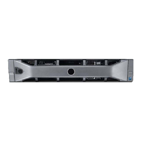
Wiring and Device Connections Wiring and Device Connections Master Server Rear Panel Connections This section details the ports and connectors on the rear panel of the Vision Master server. Power connector Output port LAN ports FIG. 2 Vision Master server rear panel Some rear panel connectors are not available with certain solutions. - Page 26 Wiring and Device Connections The following table lists the pinouts, signals, and pairing associated with the LAN connector. LAN RJ-45 Pinouts and Signals Signals Connections Pairing Color TX + 1 --------- 1 1 --------- 2 Orange-White TX - 2 --------- 2 Orange RX + 3 --------- 3...
-
Page 27: Wmv Appliance Rear Panel Connections
Wiring and Device Connections WMV Appliance Rear Panel Connections This section details the ports and connectors on the rear panel of the Vision WMV appliance: HD-15 Port The HD-15 input connector is used for WMV source streams. Use the male HD-15 port for WMV source streams. The female HD-15 port is available for an output device such as a PC monitor. - Page 28 Wiring and Device Connections The following table lists the pinout configuration for HD-15 connector to S-Video connectors: HD-15 to S-Video Pinouts HD-15 S-Video Signal S-Video Connector Pin Luminance (Y) Chrominance (C) Luminance (Y) - Return Chrominance (C) - Return The following table lists the pinout configuration for HD-15 connector to Component (RGB) or Composite connectors: HD-15 to Component (RGB) or Composite Pinouts HD-15 Pin...
-
Page 29: Vision2 Tds
Wiring and Device Connections Vision Vision TDS provides multiple live Digital Video Broadcast (DVB) or MPEG channels over a standard IP network for up to 150 users for each type of channel. See the Vision2 TDS section on page 26 for information on setting up your Digital TV appliance. -
Page 30: Set-Top Boxes
Wiring and Device Connections Set-Top Boxes The STB-02SB (FG3100-61), STB-03CC (FG3100-62), and STB-04 Set-Top Boxes (FG3100-65) support viewing live programming via a producer channel or a MPEG encoder. The set-top boxes access your Vision server and display available programming on a connected video source. The set-top boxes are used only for MPEG content. - Page 31 Wiring and Device Connections FIG. 12 displays the rear panel of the STB-04 Set-Top box. Power port HDMI port Audio/Video port SPDIF USB port IR Extender/TVI port port FIG. 12 STB-04 Set-Top Box (rear-view) Vision Operation/Reference Guide...
- Page 32 Wiring and Device Connections Vision Operation/Reference Guide...
-
Page 33: Installation
Installation Installation This chapter provides instructions on how to connect the different types of Vision systems and servers. Dealer Demo Systems The V2-DLR-DEMO-1RU Dealer Demo System (FG3100-D1K) provides two live MPEG channels and two live Digital Video Broadcasting - Terrestrial (DVB-T) multiplexes for up to 10 users over a standard IP network. - Page 34 Installation The following steps show you how to setup a typical configuration for the Dealer Demo Systems. Connect the power supply to the rear of the Dealer Demo server. Connect an RJ-45 LAN cable to LAN port one on the back of the Dealer Demo server. See FIG. 13 and FIG.
-
Page 35: Wmv Solution
Installation WMV Solution The following steps show you how to setup a typical configuration for the WMV Solution: Connect the power supply to the power connector on the rear of the Vision Master server (FIG. 15). Power connector LAN ports FIG. -
Page 36: Mpeg Solution
Installation MPEG Solution The following steps show you how to setup a typical configuration for the MPEG Solution: Attach the power supply to the power connector on the rear of the server (FIG. 15). Connect an RJ-45 LAN cable to one of the LAN ports on the back of the Vision Master server. -
Page 37: Live Mpeg Installation For Vision2 Tds
The DTV-TX03-US transmitter (FG1410-03) receives incoming ClearQAM or ATSC digital TV signals. Consult the AMX TDS Operation/Reference Guide for information on using the various digital TV transmitters available from AMX. Connect a coaxial cable to the RF IN connector on the rear of the digital TV transmitter (FIG. 19). -
Page 38: Archive Servers
Installation Archive Servers Vision Archive servers allow you to store and manage videos in Flash, WMV, MPEG-2, and MPEG-4 format for future use. The stored content can then be used to build your own channel and/or allow users to access it with Video on Demand. -
Page 39: Installing The V2-Storage-Ext800 External Raid Controller
Installation Installing the V2-STORAGE-EXT800 External RAID Controller Before installing the V2-STORAGE-EXT800 External RAID Controller, be sure to discharge any static electricity from your body by touching a grounded object. Follow these steps to install the V2-STORAGE-EXT800 External RAID Controller: Power off the V2-VOD-SERVER. Unlock the cover of the server by flipping up the locking mechanism located on the cover of the server toward the front of the device. -
Page 40: Set-Top Boxes
Installation Set-Top Boxes The STB-02SB (FG3100-61), STB-03CC (FG3100-62), and STB-04 (FG3100-65) Set-Top Boxes support viewing live programming via a producer channel or an MPEG encoder. The set-top boxes access your Vision server and display available programming on a connected video source. The set-top boxes are used only for MPEG content. -
Page 41: Configuring Your Set-Top Box
Installation Configuring Your Set-Top Box Before you can use your set-top box to view a video source, you must configure it to access your Vision server. You can use the Amino Configuration Keyboard included with your set-top box to access the configuration pages for the unit. - Page 42 Installation In the Password field, enter the password (the default is leaves) and press Enter. The STB Management screen appears (FIG. 27). FIG. 27 STB Management screen Use the arrow keys on the keyboard to access the Browser Setup option, and press Enter. The Browser Setup screen appears (FIG.
-
Page 43: Using The Remote Control
Installation Using the Remote Control The set-top box includes a universal remote control you can use to control your video display and navigate through the Vision menus. Not all buttons on the remote work with your Vision setup. While Vision supports Video on Demand, you can use only the Play, Pause, Stop, Fast-Forward, and Rewind features. -
Page 44: Stb-02Sb And Stb-03Cc Menus
Installation STB-02SB and STB-03CC Menus After the set-top box reboots, it accesses the Vision server you indicated and downloads the latest Vision menus you can use to navigate through the available channels. You can create channels and schedules through the Live (MPEG) service and Producer service. See the Live (MPEG) Service section on page 67 and Producer Service section on page 109 for more information. -
Page 45: Video On Demand
Installation Video on Demand The Video on Demand menu displays a listing of all available video on demand channels (FIG. 32). FIG. 32 Video On Demand Use the remote control to scroll through the list of the channels and press OK on the remote control to select a channel. -
Page 46: Technical Information
Installation Technical Information The Technical Information screen displays information about your set-top box, network, and display. This information is view-only. FIG. 34 Technical Information Configuration The Configuration screen enables you to change your video display settings. On this screen, you can choose to configure your margins or display output. -
Page 47: Margins
Installation Margins The Configure Margins screen enables you to adjust the position of the images on your display. Use the up and down cursor buttons on the remote control to select an option. Use the left and right cursor buttons to change the setting of the selected margin. -
Page 48: Stb-04 Menus
Installation The following table lists the configuration options. Use the up and down cursor buttons on the remote control to select an option. Use the left and right cursor buttons to change the setting of the selected option. Press the OK button to apply the new setting. -
Page 49: Adding A New Device To The Device List
Installation The following table lists the Device and Template options available in the Template Editor. These options appear across the top of the screen. Device and Template Options Device Select a device from the available list to view its template. Any new devices you add appear in this list. -
Page 50: Creating A New Template
Installation Creating a New Template Perform these steps to create a new template: Click Create New Template. A series of options appears (FIG. 40). FIG. 40 Create a New Template Enter the name of the template in the Template Name field. Use the Create new template as a copy of options menu to select the model of template you want to use. - Page 51 Installation The following table lists the settings available in the Template Editor. Template Settings Navigation: Menu Selector Color Use the color chart to select a color for the menu selector. Render top line navigation Click the check box to render the text on the navigation bar. Color Use the color chart to select a color for the text on the navigation bar.
- Page 52 Installation Template Settings (Cont.) Page Indicator: Render Click the check box to render the page indicator. Font Size Use the spin box to indicate the size of the page indicator text. You can set any value between 1 and 255. Height Use the spin box to indicate the height of the page indicator.
- Page 53 Installation FIG. 42 displays the locations of the vertical text, thumbnails, and page indicator on the user interface. Vertical Text Thumbnail Header Horizontal Margin Page Indicator FIG. 42 User Interface Example 1 FIG. 43 displays the location of the info header on the user interface. Info Heading FIG.
-
Page 54: Upgrading The Vision2 Software
Software Periodic upgrades will occasionally be available for the Vision interface. Upgrades are available by contacting AMX Tech Support at 800-932-6993. Before upgrading, it is recommended that you make a copy of the server for backup purposes. Upgrading to Vision Software Version 7.1... -
Page 55: Upgrading To Vision2 Software Version 7.2
Installation When the upgrade is complete, navigate to the directory where the files were installed, and double-click the Vision2Updater.exe file. The AMX Vision Updater opens (FIG. 45). FIG. 45 AMX Vision Updater Click Start Update. Once the update begins, it may be a few minutes before you see any progress. Once the upgrade is complete, you must manually reboot the server. - Page 56 Installation Vision Operation/Reference Guide...
-
Page 57: Accessing Servers
Accessing Servers Accessing Servers Overview Vision enables you to easily add and manage additional servers in the system. All Vision services are managed by the Vision ServicesManager web interface. Starting and Accessing Vision Perform these steps to access your server remotely: Power on the Vision server. -
Page 58: Accessing The Server
Accessing Servers Accessing the Server There are two methods you can use to access the Vision server: directly and remotely. Accessing directly requires connecting a monitor, keyboard, and mouse to the server and accessing it as you would with a typical PC. -
Page 59: Adding A Server
Accessing Servers Click Start, select Administrative Tools, and Open Windows Media Services. You will see an RPC error box, so click OK to bypass it. In Windows Media Services, select Action from the top menu, open Add Server, and enter the new server name. - Page 60 Accessing Servers Access the server’s Vision application. See the Accessing the Server section on page 48 for more information. Change the Master Server Name to the Master R710 server’s name (FIG. 49). Change the Master server name FIG. 49 Vision Server application Click Apply, and restart the application.
-
Page 61: Master Service
Master Service Master Service The Vision² Master Service is responsible for managing the licensing of all Vision² services on all of the servers in the system. It also creates the playlists for the live channels for the Windows Media Player and VLC Media Player, and creates a generic XML list for custom media players. -
Page 62: Managing A Specific Server
This is the license code which has been used to unlock the services on the server. New Server License Code This is where you would paste an updated license code supplied by AMX when you purchase additional services. Check License Code After you input a new license code, you can check that it will unlock the expected services by clicking this button. -
Page 63: Adding And Activating Services
Master Service Adding and Activating Services After successfully adding a server, you must activate the available services for it with an appropriate license key. Perform these steps to add and activate a service: Click Manage <name of server> in the services list on the left side of the page to display the available services for the server. -
Page 64: Adding An Unmanaged Channel
Master Service The following options appear on the Manage Channel Order page. Manage Channel Order Options Add Unmanaged Channel Adds an unmanaged channel to the Channel Order list. Channel Name The name of the channel as it will appear in the Channel Order list. Type The type of stream for the channel. -
Page 65: User Interface Configuration
Master Service User Interface Configuration The User Interface Configuration options enable the administrator to configure which video formats are available to the users in the sample player. The Zoom setting on the web browser should be set to 100% or the video may not appear in browser window. -
Page 66: Tablet Ui
Master Service Tablet UI Selecting the Tablet user interface configuration enables you to select a custom user interface. FIG. 56 displays the Tablet UI player. You can select a template on this screen. You must click Apply prior to using the Amino clients to access the system. -
Page 67: V2 Player
Master Service V2 Player This is a fully featured player capable of displaying both live feeds and Video on Demand in multiple formats. FIG. 57 Sample Player 1 Click the sample player under UI Configuration in the left panel to display the configuration options for the player (FIG. - Page 68 Master Service If a specific configuration option is not supported by a particular player, that option cannot be selected. The following options are available: V2 Player Configuration Options Description A single line description shown in the management interface to help with identification.
-
Page 69: Format Compatibility
Master Service Format Compatibility The following tables list the formats that are compatible with Live channels and Video on Demand. Live Channel Compatibility Amino PC Client MPEG-2/ MPEG-2 TS H.264 (AVC)/ MPEG-2 TS H.264 (AVC)/ PC Client Video on Demand Compatibility Amino PC Client MPEG-2/MPEG-2 TS... -
Page 70: Testing The Player In A Web Page
Master Service Testing the Player in a Web Page To view how the Vision player will appear, click the Test Player in a sample web page button on the V2 Player Configuration page. The player appears in a new tab in your current browser. The additional tabs in the player screen provide more options (FIG. -
Page 71: Set-Top Box Management
Master Service Set-Top Box Management Set-Top Boxes support viewing live programming via a producer channel or an MPEG encoder. The set-top boxes access your Vision server and display available programming on a connected video source. The set-top boxes are used only for MPEG content. They support viewing MPEG Video on Demand, and supports Stop, Play, Pause, Fast-Forward, and Rewind features. - Page 72 Master Service The Available Set Top Boxes area lists the set-top boxes currently detected. This list includes the name, status, channel type, and IP address of each set-top box. This list is view-only. You can select any set-top box from the list and use the options below to change its output.
-
Page 73: Configuring Vision2 For Use With Ldap
Master Service Configuring Vision for use with LDAP If you intend to use Lightweight Directory Access Protocol (LDAP), then before you begin there is an XML file on the Vision server which must be edited manually. You must edit the ldsl.xml file located in the C:\Inetpub\wwwroot\v2Services\App_Code directory. - Page 74 LDAP as the Access Control Type. Example values: Active Directory: OU=AMX UK DMG ADAM: OU=AMX UK DMG, O=AMX, C=UK Validate Click this button to apply the LDAP settings after entering them. The tree control at the bottom of the page displays the results.
-
Page 75: Restricting User Access To Content
Master Service Restricting User Access to Content In the Archive Service, when you navigate to a folder which contains videos the Restrict the users who gave access to the content in this category check box appears. When enabled, it displays the current DN selected for the restriction. - Page 76 Master Service Vision Operation/Reference Guide...
-
Page 77: Live (Mpeg) Service
Live (MPEG) Service provides a single live TV channel to the system. The Live MPEG service uses an AMX MAX-CSE encoder (FG2178-70) or other supported third-party encoder to provide the hardware encoding of video and audio signals into an MPEG-2 multicast stream. Live Services, as with all... -
Page 78: Service Settings
Live (MPEG) Service Service Settings FIG. 65 MAX Encoder Service Settings The top section of the page deals with the settings for the service itself and consists of the following options: Service Settings Options Channel Name The name of the service as it appears in the playlists. Encoder Type Use the options menu to select the type of MPEG encoder you want to configure. -
Page 79: Multicast Settings
Live (MPEG) Service Multicast Settings FIG. 66 MAX Encoder Multicast Settings The following options are available in the multicast section: Multicast Settings Options Protocol The protocol setting is fixed at UDP multicast. UDP multicast is the only supported protocol at this time. Address This is the multicast address that will be used. - Page 80 Live (MPEG) Service The following options are available in the encoding section: Encoding Settings Options Video Input The MAX encoder supports either S-Video or Composite video inputs. Video Standard The MAX encoder supports NTSC (USA and Japan) and PAL (rest of the world, excluding France) video standards.
-
Page 81: Live (Wmv) Service
Services Manager web interface to provide a unicast stream over HTTP. Configuring the AMX Vision Dual Encoder When you select Configure Encoder from the WMV Encoder menu and select AMX Vision Dual Encoder from the Encoder Type menu, the following page appears (FIG. 68): FIG. -
Page 82: Configuring The Vbrick Wmv Appliance Encoder
Live (WMV) Service Perform these steps to configure the AMX Vision Dual Encoder: Select Configure Encoder from the WMV Encoder menu. The Configure Live WMV Service page opens (FIG. 68). In the Service Name text box, enter the name of the service as you want it to appear in the left pane of the main window. -
Page 83: Service Settings
Live (WMV) Service Service Settings FIG. 70 WMV Encoder Service Settings The top section of the page deals with the settings for the service itself and consists of the following options: Service Settings Options Service Name The name of the service as it appears in the playlists. Encoder Type Use the options menu to select the type of WMV encoder you want to configure. -
Page 84: Encoding Settings
Live (WMV) Service Encoding Settings FIG. 71 WMV Encoder Encoding Settings The following options are available in the encoding section: Encoding Settings Options Enable Click to enable WMV streaming through the encoder. Note: You will receive an error if you disable a Live channel while it is being accessed by another service. -
Page 85: Viewing The Stream
Live (WMV) Service Perform these steps to configure the VBrick WMV multicast stream: Select Configure Encoder from the Encoder menu. The Live Service page opens (FIG. 68). Use the Video Input options menu to indicate whether you are connecting to the S-video, component, or composite port on the encoder. - Page 86 Live (WMV) Service Vision Operation/Reference Guide...
-
Page 87: Reflector Service
Reflector Service Reflector Service The Vision Reflector Service provides a single live TV channel to the system. Reflector can multicast a Live WMV service, MPEG channel, or a stream from the Web. The MPEG Reflector accepts both unicast and multicast Windows Media streams as its input and can provide both unicast and multicast Windows Media streams as its output. -
Page 88: Activating A Unicast Stream
Web Service URL The URL to the Web Services interface for this service. This value is automatically generated and should not be edited unless instructed by AMX. Unicast source The options menu provides a list of all the Live (WMV) encoders in the system and also an option to specify a WMV stream from the internet. -
Page 89: Mpeg Configuration
Reflector Service MPEG Configuration The MPEG reflector can receive both unicast or multicast streams and output both unicast or multicast streams. When you select the Configure Reflector from the MPEG Reflector Service Menu the following page appears (FIG. 74). FIG. 74 Configure Vision MPEG Reflector Service The following options appear on the Reflector service configuration page:... -
Page 90: Activating A Unicast Stream
Reflector Service Reflector MPEG Service Options (Cont.) NIC to multicast on The IP address of the network to use for multicasting. Unicast options The following options are only available if you select Unicast as the Stream type. Select the unicast address for this channel. Port The unicast port for this channel. -
Page 91: Dvb Service
DVB Service DVB Service The Vision DVB Service provides and manages a single Digital Video Broadcast (DVB) multiplex of live TV channels to the system. Terrestrial, satellite, and cable TV providers now use a digital rather than analog transmission systems to deliver their content. Where previously a single frequency was required for each TV channel, by using digital compression, multiple channels can be provided on a single frequency (known as a multiplex or bouquet). -
Page 92: Service Settings
DVB Service The Configure DVB Service page consists of the following sections: Service Settings FIG. 76 Service settings The top section on the page deals with the settings for the service itself and consists of the following options: Service Options Service Name The name of the service as it appears in the services menu Apply... -
Page 93: Scanning For Available Channels
DVB Service Scanning for Available Channels Perform these steps to scan for available channels on all frequencies: Select Configure DVB from the DVB Service Menu on the left pane of the window. The Configure DVB Service page appears (FIG. 75). Select the tuner you want to use from the Tuner Hardware options menu, and click Apply. -
Page 94: Channel List
DVB Service Channel List At the bottom of the page is the list of channels available on the selected frequency. This area of the page contains the following view-only information: Channel List Options Name The channel name as provided by the broadcaster Type The type of channel, either Digital TV or Digital Radio Multicast... -
Page 95: Archive Service
These settings define the protocols and paths used to access the content in the archive. Please do not modify this setting unless instructed to do so by AMX. Filenames should only contain the characters A-Z, 0-9, spaces and underscores. If a filename is imported that contains the special character, it could cause error. -
Page 96: Supported Video On Demand Media Formats
Archive Service Supported Video on Demand Media Formats Video on Demand service supports four types of media files (WMV, MPEG-2, MPEG-4, and FLV), however, Video on Demand can only support one file type at a time. To change the supported Video on Demand media format, an administrator must manually edit the vcArchiveBrowserConfig.xml file found in the /v2Service/UI folder. -
Page 97: Configuring Metadata
Archive Service The bitrates specified above are for playback on a PC unless otherwise stated. Configuring Metadata When you select Configure Metadata from the Archive Service Menu the following page appears (FIG. 81). FIG. 81 Metadata Configuration The Archive supports two styles of metadata: ... - Page 98 Archive Service To create a new table section click Add new Table section, select the number of rows and columns, and click Add Table. Add New Table Section Options Section Name This is the name of the section as it appears on the left side of the page and also when editing metadata in the archive.
-
Page 99: Browsing And Managing Content
Archive Service FIG. 83 displays how the information appears with actual metadata in the main archive. FIG. 83 Metadata Example If you make any changes that you want to keep, you must click the Save Changes button. Browsing and Managing Content All content is stored in the archive in a hierarchical structure, much like folders on a PC, and is displayed in a similar manner in the archive service menu. -
Page 100: Archive Sort Function
Click the Sort Entire Archive button, a warning box will appear to highlight that the process cannot be undone. AMX advises that the content.xml for the archive should be backed up before proceeding. Click Yes to sort the entire archive. Note that you may get a security prompt if authentication is enabled. -
Page 101: Adding An Online Video To An Archive
Archive Service Adding an Online Video to an Archive Vision2 enables you to provide content links to online videos from websites such as YouTube or MediaSite. Follow these steps to add an online video to an archive. Click the Content folder under one of your archives on the left side of the page. On the Content screen, click Add an online video. -
Page 102: Playing A Video Within The Archive
Archive Service The default metadata consists of three sections: Metadata Options Video Formats This provides an visual representation of the currently uploaded file formats. Passing the cursor over an uploaded video format displays the upload date of the format. Video Information Provides technical information on the individual video files. -
Page 103: Uploading Additional Versions Of The Same File
Archive Service If you select a text-based section (in this case Podcast Info) and click Edit Section, the options change appropriately to display the usual text editing options like font type, size, and weight (FIG. 88). Text editing options FIG. 88 Editing Metadata If you select a table-based section to edit, the options change again. - Page 104 Archive Service Vision Operation/Reference Guide...
-
Page 105: Thumbnail Editor
Thumbnail Editor Thumbnail Editor The thumbnail editor allows users to create video thumbnails, effectively bookmarks to certain points in your video. Each thumbnail contains an image captured from the video at the time of creation along with some descriptive text to describe its purpose. The thumbnail editor consists of two screens: ... -
Page 106: Login To Thumbnail Editor
Thumbnail Editor Login to Thumbnail Editor Login to the Thumbnail editor as follows: Enter the application link provided by your system administrator into your web browser. For example, http://<Server Name>/ThumbsEdit.aspx. Replace <server name> with the name or IP address of your Vision Server. - Page 107 Thumbnail Editor The Archive Navigation Pane works in a similar way to windows explorer: Click the arrows beside the folders to expand or contract them, revealing or hiding the contents respectively Videos are indicated by filmstrip icons. The video title appears to the right of the icon. MP3 files are not shown.
- Page 108 Thumbnail Editor You can carry out the following actions on videos in the Selected Video Area: Play video in thumbnail editor - hover over the video image to reveal a blue play icon. Click this icon to go to the thumbnail editor and start the video playing (from the beginning). Note that if someone is already playing/editing this video then you will see the following error message: FIG.
-
Page 109: Thumbnail Editor Screen
Thumbnail Editor Thumbnail Editor Screen The thumbnail editor screen (FIG. 96) consists of two main areas: Thumbnail bar - Contains a number of thumbnails arranged in time order. Thumbnails at the top occur earlier in the video than those further down. ... -
Page 110: Creating A Thumbnail
Thumbnail Editor Creating a Thumbnail You can create up to 200 thumbnails for a video as follows: Start the video playing, ether by clicking play in the video playback panel or by clicking play on a thumbnail image. Wait until the video reaches the moment you want to mark. Click Add new Thumbnail to add a new thumbnail to the Thumbnail bar. -
Page 111: Video Playback Area
Thumbnail Editor Video Playback Area The video playback area is used for the following actions: Viewing a video. Finding the right position in a video to create a thumbnail. Viewing thumbnails that have already been created. You can control the playback using a small panel at the bottom of the screen, see FIG. 99. The main controls are as follows: ... - Page 112 Thumbnail Editor Vision Operation/Reference Guide...
-
Page 113: Thumbnail Viewer
Thumbnail Viewer Thumbnail Viewer The thumbnail viewer allows users to view video thumbnails, effectively bookmarks to certain points in your videos. Each thumbnail contains an image captured from the video at the time of creation along with some descriptive text to describe its purpose. The thumbnail viewer consists of two screens: ... -
Page 114: Archive Navigation Screen
Thumbnail Viewer Archive Navigation Screen The Archive Navigation Screen consists of two main areas (see FIG. 100): The Archive Navigation Pane - used to navigate through the video archive and select those videos you wish to create/view thumbnails for. ... - Page 115 Thumbnail Viewer You can also select videos using the Search bar. Enter the text you want to search for and click the magnifying glass. Videos with a title, metadata, description, or thumbnail which contain this text are added to the Selected Video Area.
-
Page 116: Thumbnail Viewer Screen
Thumbnail Viewer Thumbnail Viewer Screen The thumbnail viewer screen (FIG. 104) consists of two main areas: Thumbnail bar - Contains a number of thumbnails arranged in time order. Thumbnails at the top occur earlier in the video than those further down. ... -
Page 117: Video Playback Area
Thumbnail Viewer Video Playback Area The video playback area is used for the following actions: Viewing a video. Viewing thumbnails. You can control the playback using a small panel at the bottom of the screen, see FIG. 105. The main controls are as follows: ... - Page 118 Thumbnail Viewer Vision Operation/Reference Guide...
-
Page 119: Producer Service
Producer Service Producer Service Overview The Vision Producer Services provides a single scheduled TV channel to the system. Producer schedules a unicast of WMV files or a multicast of MPEG-2, MP4 H.264, or WMV files or a live channel from a Vision archive. -
Page 120: Multicasting With Producer
The name of the service as it appears in the playlists. Web Service URL The URL to the Web Services interface for this service. This value is automatically generated and should not be edited unless instructed by AMX. Stream Address Address... -
Page 121: Setting Up An Intermission
Producer Service Setting Up an Intermission If there is no content scheduled for a certain period of time, Producer enables you to set an intermission source which automatically plays an MPEG-2 or WMV file from a Vision archive, a multicast MPEG-2 source such as a DVB or Live MPEG channel, or a unicast WMV source such as a live WMV channel. -
Page 122: Viewing The Stream
Producer Service The following options are available on the top toolbar: Edit Schedule Options Snap When moving a program or adding a program to the schedule, the Snap limit defines the program time start boundary. For example, a 15 minute Snap setting only allows programs to be scheduled at :00, :15, :30, and :45 minutes past each hour. -
Page 123: Record Service
Service Name The name of the service as in Services Manager. Web Service URL The URL to the Web Services interface for this service. This value is automatically generated and should not be edited unless instructed by AMX. Vision Operation/Reference Guide... -
Page 124: Recording Settings
Mapped Archive Path This defines the physical path to the archive and should only modified if instructed by AMX. Write to Archive This defines the archive in which you want the recordings to save. -
Page 125: Recording A Video Stream
Record Service Recording a Video Stream Perform these steps to record a video stream: Select Configure DVR from the Record Services menu on the left pane of the window. The Record Service page appears (FIG. 108). Select the IP address of the network you are using from the NIC to Use options menu. Select Continuous from the Recording type options menu. -
Page 126: Scheduled Recording
Record Service Scheduled Recording The Scheduled Record feature allows you to schedule when a live service is to be recorded. You must select the source from which to record and enable the service before editing the schedule. Scheduled recordings are only supported in the Live MPEG service and in 10 minute increments. - Page 127 Record Service Vision Operation/Reference Guide...
- Page 128 - Schedules and registration for any AMX University course - Travel and hotel information - Your individual certification requirements and progress 3000 RESEARCH DRIVE, RICHARDSON, TX 75082 USA • 800.222.0193 • 469.624.8000 • 469-624-7153 fax • 800.932.6993 technical support • www.amx.com...
Need help?
Do you have a question about the Vision 2 and is the answer not in the manual?
Questions and answers