
Subscribe to Our Youtube Channel
Related Manuals for FlowLine DataView LI55


Summary of Contents for FlowLine DataView LI55
- Page 1 ™ DataView Level Controller LI55 Instruction Manual Flowline, Inc. | 10500 Humbolt Street, Los Alamitos, CA 90720 LIM60000FL2 Rev C p 562.598.3015 f 562.431.8507 w flowline.com MN301033 Rev B1...
- Page 2 Instruction Manual DISCLAIMER The information contained in this document is subject to change without notice. Flowline makes no representations or warranties with respect to the contents hereof and specifically disclaims any implied warranties of merchantability or fitness for a particular purpose.
-
Page 3: Table Of Contents
DataView™ LI55 Level Controller Instruction Manual TABLE OF CONTENTS INTRODUCTION ....................7 ORDERING INFORMATION ................7 SPECIFICATIONS .................... 8 General ...................... 8 Process ....................10 Relays ...................... 11 Isolated 4-20 mA Transmitter Output ............ 12 COMPLIANCE INFORMATION ..............13 Safety ...................... 13 Electromagnetic Compatibility .............. - Page 4 DataView™ LI55 Level Controller Instruction Manual Full Menu Display Functions & Messages ............ 37 Full Menu ......................40 SETTING UP THE METER WITH THE FULL MENU (sEtuP) ......41 Setting the Input Signal (InPut) .............. 42 Dual-Scale ..................42 Setting Custom Units or Tags (units) ............ 43 Setting the Decimal Point (dEC Pt) ............
- Page 5 DataView™ LI55 Level Controller Instruction Manual Acknowledging Relays ................66 Pump Alternation Control Applications (ALtErn) ........67 Setting Up the Interlock Relay (Force On) Feature ........70 SCALING THE 4-20 MA ANALOG OUTPUT (Aout) ........71 RESET MENU (rEsEt) ..................72 CONTROL MENU (ContrL) ................
- Page 6 DataView™ LI55 Level Controller Instruction Manual TABLE OF FIGURES Figure 1. 1/8 DIN Panel Cutout Dimensions ........15 Figure 2. Panel Mounting Details ............16 Figure 3. Meter Dimensions - Side View ........... 17 Figure 4. Meter Dimensions - Top View ..........17 Figure 5.
-
Page 7: Introduction
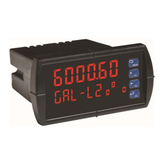
Instruction Manual INTRODUCTION The DataView LI55 is a multi-purpose, easy to use digital process meter ideal for level, flow rate, temperature, or pressure transmitter applications. It accepts current and voltage signals (e.g. 4-20 mA, 0-10 V). Three of the front panel buttons can be custom-programmed for a specific operation. -
Page 8: Specifications
DataView™ LI55 Level Controller Instruction Manual SPECIFICATIONS Except where noted all specifications apply to operation at +25°C. General Main display: 0.60" (15 mm) high, red LEDs Display Second display: 0.46" (12 mm) high, red LEDs 6 digits each (-99999 to 999999), with lead zero blanking Eight user selectable intensity levels Display Intensity... - Page 9 DataView™ LI55 Level Controller Instruction Manual 4 kV input/output-to-power line Isolation 500 V input-to-output or output-to-P+ supply Installation Overvoltage Category II: Overvoltage Local level with smaller transient overvoltages than Installation Category Overvoltage Category III. Operating temperature range: -40 to 65°C Environmental Storage temperature range: -40 to 85°C Relative humidity: 0 to 90% non-condensing...
-
Page 10: Process
DataView™ LI55 Level Controller Instruction Manual Process Input Field selectable: Inputs 0-20, 4-20 mA, 10 V (0-5, 1-5, 0-10 V) ±0.03% of calibrated span ±1 count, Accuracy square root & programmable exponent accuracy range: 10-100% of calibrated span 0.005% of calibrated span/C max from 0 to 65C ambient, Temperature Drift 0.01% of calibrated span/C max from -40 to 0C ambient Linear, square root, programmable exponent, or... -
Page 11: Relays
DataView™ LI55 Level Controller Instruction Manual Relays 2 or 4 SPDT (Form C) internal and/or 4 SPST (Form A) external; Rating rated 3 A @ 30 VDC and 125/250 VAC resistive load; 1/14 HP (≈ 50 W) @ 125/250 VAC for inductive loads Noise suppression is recommended for each relay contact switching Noise inductive loads;... -
Page 12: Isolated 4-20 Ma Transmitter Output
DataView™ LI55 Level Controller Instruction Manual Isolated 4-20 mA Transmitter Output Process variable (PV), max, min, set points 1-8, or manual control Output Source mode 1.000 to 23.000 mA for any display range Scaling Range Factory calibrated: 4.000 to 20.000 = 4-20 mA output Calibration 23.000 mA maximum for all parameters: Analog Out... -
Page 13: Compliance Information
DataView™ LI55 Level Controller Instruction Manual COMPLIANCE INFORMATION Safety USA & Canada UL & -UL LISTED UL 508 Industrial Control Equipment E193723 UL File Number UL Type 4X, NEMA 4X, IP65; panel gasket provided Front Panel EN 61010-1:2001 Low Voltage Safety requirements for measurement, control, and Directive laboratory use... -
Page 14: Safety Information
Testing was conducted on LI55 meters installed through the covers of grounded metal enclosures with cable shields grounded at the point of entry representing installations designed to optimize EMC performance. Declaration of Conformity available at flowline.com SAFETY INFORMATION CAUTION: Read complete... -
Page 15: Installation
DataView™ LI55 Level Controller Instruction Manual INSTALLATION There is no need to remove the meter from its case to complete the installation, wiring, and setup of the meter for most applications. Instructions are provided for setting up a 12/24 VDC powered meter to operate from 12 VDC (see page18) and for changing the transmitter power supply to output 5 or 10 VDC instead of 24 VDC (see page18). -
Page 16: Figure 2. Panel Mounting Details
DataView™ LI55 Level Controller Instruction Manual Gasket Removable Connectors Panel Mounting Mounting Bracket Screw Figure 2. Panel Mounting Details MN301033 Rev B1... -
Page 17: Mounting Dimensions
DataView™ LI55 Level Controller Instruction Manual Mounting Dimensions Figure 3. Meter Dimensions - Side View Figure 4. Meter Dimensions - Top View MN301033 Rev B1... -
Page 18: Configuration For 12 Or 24 Vdc Power
DataView™ LI55 Level Controller Instruction Manual Configuration for 12 or 24 VDC Power Do not exceed voltage rating of the selected configuration. Warning! Meters equipped with the 12/24 VDC power option are shipped from the factory ready to operate from 24 VDC. To configure the meter for 12 VDC power: Remove all the connectors. -
Page 19: Connections
Configure the J4 jumper, located behind the input signal connector, for the desired excitation voltage as shown. Figure 6. Transmitter Supply Voltage Selection (Do not change if using a Flowline 4-20 mA transmitter) Connections All connections are made to removable screw terminal connectors located at the rear of the meter. -
Page 20: Connectors Labeling
The connectors’ label, affixed to the meter, shows the location of all connectors available with requested configuration. Do not connect any equipment other than Flowline’s expansion modules, cables, or meters to the RJ45 M-LINK connector. Otherwise damage will occur to the equipment and the meter. -
Page 21: Signal Connections
DataView™ LI55 Level Controller Instruction Manual Signal Connections Signal connections are made to a six-terminal connector labeled SIGNAL on Figure 7. The COM (common) terminal is the return for the 4-20 mA and the 10 V input signals. Current and Voltage Connections The following figures show examples of current and voltage connections. -
Page 22: Relay Connections
DataView™ LI55 Level Controller Instruction Manual Figure 11. Voltage Input Connections The meter is capable of accepting any voltage from -10 VDC to +10 VDC. Relay Connections Relay connections are made to two six-terminal connectors labeled RELAY1 – RELAY4 on Figure 7. Each relay’s C terminal is common only to the normally open (NO) and normally closed (NC) contacts of the corresponding relay. -
Page 23: Switching Inductive Loads
DataView™ LI55 Level Controller Instruction Manual Switching Inductive Loads The use of suppressors (snubbers) is strongly recommended when switching inductive loads to prevent disrupting the microprocessor’s operation. The suppressors also prolong the life of the relay contacts. Suppression can be obtained with resistor-capacitor (RC) networks assembled by the user or purchased as complete assemblies. -
Page 24: F4 Digital Input Connections
DataView™ LI55 Level Controller Instruction Manual F4 Digital Input Connections A digital input, F4, is standard on the meter. This digital input is connected with a normally open contact across F4 and COM, or with an active low signal applied to F4. -
Page 25: External Relays Connections
DataView™ LI55 Level Controller Instruction Manual External Relays Connections The relay expansion module LI56-1400 is connected to the meter using a CAT5 cable provided with each module. The two RJ45 connectors on the expansion modules are identical and interchangeable; they are used to connect additional modules to the system. -
Page 26: Interlock Relay Feature
DataView™ LI55 Level Controller Instruction Manual Interlock Relay Feature As the name implies, the interlock relay feature reassigns one, or more, alarm/control relays for use as interlock relay(s). An Interlock contact is wired to the digital input and triggers the interlock relay. This feature is enabled by configuring the relay and digital input (see page 70). -
Page 27: Setup And Programming
DataView™ LI55 Level Controller Instruction Manual SETUP AND PROGRAMMING The meter is factory calibrated prior to shipment to read in milliamps and volts depending on the input selection. The calibration equipment is certified to NIST standards. Overview There are no jumpers to set for the meter input selection. Setup and programming is done through the front panel buttons. -
Page 28: Setting Numeric Values
DataView™ LI55 Level Controller Instruction Manual Setting Numeric Values The numeric values are set using the Right and Up buttons. Press Right button to select next digit and Up button to increment digit value. The digit being changed is displayed brighter than the rest. Press and hold Up button to auto-increment the display value. -
Page 29: Menu Levels
DataView™ LI55 Level Controller Instruction Manual Menu Levels The DataView has three menu levels available for quicker setup and programming. Main Menu The Main Menu contains all of the most commonly used features of the DataView meter. These features are duplicated and expanded upon by the Full Menu, see page 37. - Page 30 DataView™ LI55 Level Controller Instruction Manual Full Menu The Full Menu features added functionality and settings allowing for a more customized setup and programming. It consists of the following functions: Setup, Reset, Control, and Password. Press and hold the Menu button for 5 seconds to enter the Full Menu. Press the Menu button to exit.
- Page 31 DataView™ LI55 Level Controller Instruction Manual Advanced Menu To simplify the setup process, functions not needed for most applications are located in the Advanced Features menu. Press and hold the Menu button for 5 seconds to enter the full main menu. From Setup, press and hold the Menu button for 3 seconds to access the advanced features of the meter.
-
Page 32: Front Panel Buttons And Status Led Indicators
DataView™ LI55 Level Controller Instruction Manual Front Panel Buttons and Status LED Indicators Button Description Status Symbol Alarm 1-8 indicator Menu Flashing: Relay in manual Right control mode Flashing: Tare Flashing: Relay interlock Enter switch open Note: Note: F4 is a digital input. Alarms 5-8 are LEDs for relays in manual mode flash enabled when relay expansion module with the “M”... -
Page 33: Main Menu Display Functions & Messages
DataView™ LI55 Level Controller Instruction Manual Main Menu Display Functions & Messages The meter displays various functions and messages during setup, programming, and operation. The following table shows the main menu functions and messages in the order they appear in the menu. Display Parameter Action/Setting Description... -
Page 34: Main Menu
DataView™ LI55 Level Controller Instruction Manual Main Menu The Main Menu contains all of the most commonly used features of the DataView meter. These features are duplicated and expanded upon by the Full Menu, see page 20. Press Menu button to enter the main menu then press the Up button to scroll main menu. -
Page 35: Setting The Units (Units)
DataView™ LI55 Level Controller Instruction Manual Setting the Units (units) Select units from list or enter a custom tag to be shown on the lower display. Press the Up button to scroll through the unit choices. Press Enter to accept unit choice. -
Page 36: Setting The Relay Operation (Relay)
DataView™ LI55 Level Controller Instruction Manual Setting the Relay Operation (rElAy) To set the relay's setpoints and reset points see Programming Set and Reset Points on page 54. Scaling the 4-20 mA Analog Output (Aout) The 4-20 mA analog output can be scaled to provide a 4-20 mA signal for any display range selected. -
Page 37: Full Menu Display Functions & Messages
DataView™ LI55 Level Controller Instruction Manual FULL MENU DISPLAY FUNCTIONS & MESSAGES The meter displays various functions and messages during setup, programming, and operation. The following table shows the main menu functions and messages in the order they appear in the menu. Display Parameter Action/Setting Description... - Page 38 DataView™ LI55 Level Controller Instruction Manual Display Parameter Action/Setting Description MN301033 Rev B1...
- Page 39 DataView™ LI55 Level Controller Instruction Manual Display Parameter Action/Setting Description MN301033 Rev B1...
-
Page 40: Full Menu
DataView™ LI55 Level Controller Instruction Manual FULL MENU The Full Menu features added functionality and settings allowing for a more customized setup and programming. It consists of the following functions: Setup, Reset, Control, and Password. Press and hold Menu button for 5 seconds to enter the full menu then press the Up button to scroll main menu. -
Page 41: Setting Up The Meter With The Full Menu (Setup)
DataView™ LI55 Level Controller Instruction Manual SETTING UP THE METER WITH THE FULL MENU (sEtup) The Setup menu is used to select: Input signal the meter will accept Dual-scale feature for some level applications Select the display units/tags Decimal point position Programming Menu Display parameter and intensity Relay operation... -
Page 42: Setting The Input Signal (Input)
DataView™ LI55 Level Controller Instruction Manual Setting the Input Signal (Input) Enter the Input menu to set up the meter to display current (mA) or voltage (volt) inputs. The default input is mA, and it does not need to be changed when using current inputs. -
Page 43: Setting Custom Units Or Tags (Units)
DataView™ LI55 Level Controller Instruction Manual Setting Custom Units or Tags (units) Enter the input unit or custom tag that will be displayed if d unit is selected as the little display parameter. See the flow chart on page 51 to access the display menu to show the unit or tag on the lower display. -
Page 44: Setting The Decimal Point (Dec Pt)
DataView™ LI55 Level Controller Instruction Manual Setting the Decimal Point (dEc pt) The decimal point may be set with up to five decimal places or with no decimal point at all. Pressing the Right button moves the decimal point one place to the right until no decimal point is displayed, and then it moves to the leftmost position. -
Page 45: Programming The Meter (Prog)
DataView™ LI55 Level Controller Instruction Manual Programming the Meter (proG) It is very important to read the following information, before proceeding to program the meter: The meter is factory calibrated prior to shipment to read in milliamps and volts depending on the input selection. The calibration equipment is certified to NIST standards. -
Page 46: Multi-Point Calibration & Scaling
DataView™ LI55 Level Controller Instruction Manual Multi-Point Calibration & Scaling The meter is set up at the factory for 2-point linear calibration. The number of points for multi-point calibration/scaling is set up in the Advanced Features menu. Up to 32 linearization points may be selected for PV1 and up to 8 linearization points may be selected for PV2. -
Page 47: Dual-Scale For Level Application
DataView™ LI55 Level Controller Instruction Manual Dual-Scale for Level Application The analog input can be displayed in two different scales, by enabling the dual- scale feature (d-SCAL) in the Setup-Input menu, see page 41. To enable the dual-scale feature for some level applications you must select d- SCAL in the Input selection menu. - Page 48 DataView™ LI55 Level Controller Instruction Manual Error Message (Error) An error message indicates that the calibration or scaling process was not successful. After the error message is displayed, the meter reverts to the input prior to the failure during calibration or scaling and to input 1 during internal calibration, allowing the appropriate input signal to be applied or programmed.
-
Page 49: Calibrating The Meter With External Source (Cal)
DataView™ LI55 Level Controller Instruction Manual Calibrating the Meter with External Source (CAl) Note: To scale the meter without a signal source refer to Scaling the Meter (SCALE), page 46. The meter can be calibrated to display the process variable in engineering units by applying the appropriate input signal and following the calibration procedure. -
Page 50: Setting The Display Parameter & Intensity (Dsplay)
DataView™ LI55 Level Controller Instruction Manual Setting the Display Parameter & Intensity (dsplAy) The main display (Big) can be programmed to display: Process value 1 (PV1) Process value 2 (PV2) Percent of PV1 (PCT) Relay set points Max & min values Display reading and units Display gross Toggle net &... -
Page 51: Display Setup Menu
DataView™ LI55 Level Controller Instruction Manual Display Setup Menu ENTER ENTER ENTER ENTER ENTER ENTER ENTER After setting up the input and display, press the Menu button to exit programming and skip the rest of the setup menu. Press the Menu button again and the Up button to reach the Program menu and complete the scaling or calibration of the meter. -
Page 52: Setting The Relay Operation (Relay)
DataView™ LI55 Level Controller Instruction Manual SETTING THE RELAY OPERATION (relay) This menu is used to set up the operation of the relays. During setup, the relays do not follow the input and they will remain in the state found prior to entering the Relay menu. Caution! Relay action [Available on full main menu only] Automatic reset only (non-latching) [default]... -
Page 53: Setting The Relay Action
DataView™ LI55 Level Controller Instruction Manual Setting the Relay Action Operation of the relays are programmed in the Action menu. The relays may be set up for any of the following modes of operation: Automatic reset (non-latching) [default & typical for most applications] Automatic + manual reset at any time (non-latching) Latching (manual reset only, at any time) Latching with Clear (manual reset only after alarm condition has... -
Page 54: Programming Set And Reset Points
DataView™ LI55 Level Controller Instruction Manual Programming Set and Reset Points High alarm indication: program set point above reset point. Low alarm indication: program set point below reset point. The deadband is determined by the difference between set and reset points. Minimum deadband is one display count. -
Page 55: Relay And Alarm Operation Diagrams
DataView™ LI55 Level Controller Instruction Manual RELAY AND ALARM OPERATION DIAGRAMS The following graphs illustrate the operation of the relays, status LEDs, and ENTER button. High Alarm Operation (Set > Reset) For Manual reset mode, ENTER can be pressed anytime to turn "off" relay. To detect a new alarm condition, the signal must go below the set point, and then go above it. -
Page 56: Low Alarm Operation (Set < Reset)
DataView™ LI55 Level Controller Instruction Manual Low Alarm Operation (Set < Reset) For Manual reset mode, ENTER can be pressed anytime to turn "off" relay. For relay to turn back “on”, signal must go above set point and then go below it. MN301033 Rev B1... -
Page 57: High Alarm With Fail-Safe Operation (Set > Reset)
DataView™ LI55 Level Controller Instruction Manual High Alarm with Fail-Safe Operation (Set > Reset) Note: Relay coil is energized in non-alarm condition. In case of power failure, relay will go to alarm state. MN301033 Rev B1... -
Page 58: Low Alarm With Fail-Safe Operation (Set < Reset)
DataView™ LI55 Level Controller Instruction Manual Low Alarm with Fail-Safe Operation (Set < Reset) Note: Relay coil is energized in non-alarm condition. In case of power failure, relay will go to alarm state. MN301033 Rev B1... -
Page 59: Pump Alternation Control Operation
DataView™ LI55 Level Controller Instruction Manual MN301033 Rev B1... -
Page 60: Relay Sampling Operation
DataView™ LI55 Level Controller Instruction Manual Relay Sampling Operation Input Reset Sample Sample Sample Time Time Time Relay When the signal crosses the set point, the relay trips and the sample time starts. After the sample time has elapsed, the relay resets. The cycle repeats every time the set point is crossed, going up for high alarms and going down for low alarms. -
Page 61: Signal Loss Or Loop Break Relay Operation
DataView™ LI55 Level Controller Instruction Manual Signal Loss or Loop Break Relay Operation The following graph shows the loop break relay operation for a high alarm relay. Input Reset de-energized energized Relay Loop Break = Ignore Relay Loop Break = Off Relay Loop Break = On When the meter detects a break in the 4-20 mA loop, the relay will go to one of... -
Page 62: Time Delay Operation
DataView™ LI55 Level Controller Instruction Manual Time Delay Operation The following graphs show the operation of the time delay function. When the signal crosses the set point, the On time delay timer starts and the relay trips when the time delay has elapsed. If the signal drops below the set point (high alarm) before the time delay has elapsed, the On time delay timer resets and the relay does not change state. -
Page 63: Relay Operation Details
DataView™ LI55 Level Controller Instruction Manual RELAY OPERATION DETAILS Overview The relay capabilities of the meter expand its usefulness beyond simple indication to provide users with alarm and control functions. These capabilities include front panel alarm status LEDs as well as either 2 or 4 optional internal relays and/or 4 external relays expansion module. -
Page 64: Front Panel Leds
DataView™ LI55 Level Controller Instruction Manual Front Panel LEDs The LEDs on the front panel provide status indication for the following: Status Status Alarm 1 Alarm 5 Alarm 2 Alarm 6 Alarm 3 Alarm 7 Alarm 4 Alarm 8 The meter is supplied with four alarm points that include front panel LEDs to indicate alarm conditions. -
Page 65: Non-Latching Relay (Auto)
DataView™ LI55 Level Controller Instruction Manual Non-Latching Relay ( Auto ) Automatic reset only Condition Relay Normal Alarm Ack (No effect) Normal In this application, the meter is set up for automatic reset (non-latching relay). Acknowledging the alarm while it is still present has no effect on either the LED or the relay. -
Page 66: Latching Relay (Lt-Clr)
DataView™ LI55 Level Controller Instruction Manual Latching Relay (Lt-Clr) Manual reset only after alarm condition has cleared Condition Relay Normal Alarm Ack (No effect) Normal In this application, the meter is set up for manual reset only after the signal passes the reset point (alarm condition has cleared). -
Page 67: Pump Alternation Control Applications (Altern)
DataView™ LI55 Level Controller Instruction Manual Pump Alternation Control Applications ( AltErn ) For pump control applications where two or more similar pumps are used to control the level of a tank or a well, it is desirable to have all the pumps operate alternately. - Page 68 DataView™ LI55 Level Controller Instruction Manual Application #2: Pump Alternation Using Relays 3 & 4 Relays 1 and 2 are set up for low and high alarm indication. Relays 3 and 4 are set up for pump alternation. Set and Reset Point Programming Relay Set Point Reset Point...
- Page 69 DataView™ LI55 Level Controller Instruction Manual If the backup pump is not able to keep up, and the level reaches 7000 gallons, relay #4 transfers and starts the main pump as well. Relay #2 trips the High Level Alarm at 7500 gallons and resets at 6900 gallons.
-
Page 70: Setting Up The Interlock Relay (Force On) Feature
DataView™ LI55 Level Controller Instruction Manual Setting Up the Interlock Relay (Force On) Feature Relays 1-4 can be set up as interlock relays. To set up the relays for the interlock feature: 1. Access the Setup – Relay – Action menu and set the action to off. ENTER ENTER ENTER... -
Page 71: Scaling The 4-20 Ma Analog Output (Aout)
DataView™ LI55 Level Controller Instruction Manual Interlock Relay Operation Example Relay 1 is configured to energize (the front panel LED is off) when SW1 or SW2 switches (above) are closed. If either of the contacts set in series with the digital input open, the corresponding front panel LED flashes indicating this condition. -
Page 72: Reset Menu (Reset)
DataView™ LI55 Level Controller Instruction Manual RESET MENU ( rEsEt ) The Reset menu is used to reset the maximum or minimum reading (peak or valley) reached by the process; both may be reset at the same time by selecting “reset high &... -
Page 73: Setting Up The Password (Pass)
DataView™ LI55 Level Controller Instruction Manual SETTING UP THE PASSWORD ( pAss ) The Password menu is used for programming three levels of security to prevent unauthorized changes to the programmed parameter settings. Pass 1: Allows use of function keys and digital input Pass 2: Allows use of function keys, digital input and editing set/reset pointsPass 3: Restricts all programming, function keys, and digital input. -
Page 74: Making Changes To A Password Protected Meter
DataView™ LI55 Level Controller Instruction Manual Making Changes to a Password Protected Meter If the meter is password protected, the meter will display the message Locd (Locked) when the Menu button is pressed. Press the Enter button while the message is being displayed and enter the correct password to gain access to the menu. -
Page 75: Advanced Features Menu
DataView™ LI55 Level Controller Instruction Manual ADVANCED FEATURES MENU To simplify the setup process, functions not needed for most applications are located in the Advanced Features menu. Press and hold the Menu button for 5 seconds to enter the full main menu. From Setup, press and hold the Menu button for 3 seconds to access the advanced features of the meter. -
Page 76: Advanced Features Menu & Display Messages
DataView™ LI55 Level Controller Instruction Manual Advanced Features Menu & Display Messages The following table shows the functions and messages of the Advanced Features menu in the order they appear in the menu. MN301033 Rev B1... - Page 77 DataView™ LI55 Level Controller Instruction Manual MN301033 Rev B1...
- Page 78 DataView™ LI55 Level Controller Instruction Manual MN301033 Rev B1...
-
Page 79: Noise Filter (Filter)
DataView™ LI55 Level Controller Instruction Manual Noise Filter ( filtEr ) The noise filter is available for unusually noisy signals that cause an unstable process variable display. The noise filter averages the input signal over a certain period. The filter level determines the length of time over which the signal is averaged. -
Page 80: Select Menu (Select)
DataView™ LI55 Level Controller Instruction Manual Select Menu ( SElEct ) The Select menu is used to select the signal input conditioner applied to the input (linear, square root, programmable exponent, or round horizontal tank), low-flow cutoff, and analog output programming. The multi-point linearization is part of the linear function selection. - Page 81 DataView™ LI55 Level Controller Instruction Manual Square Root Linearization ( SquArE ) The square root function can be used to linearize the signal from a differential pressure transmitter and display flow rate in engineering units. Programmable Exponent Linearization ( ProG E ) The programmable exponent can be used to linearize the signal from level transmitters in open-channel flow applications using weirs and flumes.
- Page 82 DataView™ LI55 Level Controller Instruction Manual Round Horizontal Tank Linearization ( rHt ) This function automatically calculates the volume in a round horizontal tank with flat ends. Set the display for the desired decimal point and engineering units before entering the round horizontal tank function. Select units, inches or cm for the tank dimensions.
-
Page 83: Low-Flow Cutoff (Cutoff)
DataView™ LI55 Level Controller Instruction Manual Low-Flow Cutoff ( CutofF ) The low-flow cutoff feature allows the meter to be programmed so that the often- unsteady output from a differential pressure transmitter, at low flow rates, always displays zero on the meter. The cutoff value may be programmed from 0 to 999999. -
Page 84: Programmable Function Keys User Menu (User)
DataView™ LI55 Level Controller Instruction Manual Programmable Function Keys User Menu ( usEr ) The User menu allows the user to assign the front panel function keys F1 (RIGHT), F2 (UP), and F3 (ENTER), and the digital input F4, to access most of the menus or to activate functions immediately (e.g. -
Page 85: Tare (Tare)
DataView™ LI55 Level Controller Instruction Manual Tare ( tArE ) The tare function zero’s out the display. In the case of scale weight, tare is used to eliminate container weight and provide net weight readings. There are two tare functions; Capture Tare and Reset Tare. When the capture tare function is used, the display reading is offset by the displayed amount to make the displayed value zero. -
Page 86: Internal Source Calibration (Ical)
DataView™ LI55 Level Controller Instruction Manual Internal Source Calibration ( ICAL ) The meter is factory calibrated prior to shipment to read in milliamps and volts depending on the input selection. The calibration equipment is certified to NIST standards. The use of calibrated signal sources is necessary to calibrate the internal source of the meter. - Page 87 DataView™ LI55 Level Controller Instruction Manual The display moves to the high input calibration (C Hi). Apply the high input signal and press Enter. Set the display for the high input calibration, in the same way as it was set for the low input calibration, typically 20.000 mA. ENTER ENTER ENTER...
-
Page 88: Meter Copy Function (Copy)
DataView™ LI55 Level Controller Instruction Manual Error Message ( Error ) An error message indicates that the calibration or scaling process was not successful. The error message might be caused by any of the following conditions: Input signal is not connected to the proper terminals, or it is connected backwards. - Page 89 DataView™ LI55 Level Controller Instruction Manual Meter Copy or Cloning Instructions Do not connect the two meters to the same signal source while cloning. Internal calibration may be affected. Caution! Connect two meters using a LI56-1000 meter copy cable. Using standard CAT5 or other cable will cause damage to both meters.
-
Page 90: Meter Operation
DataView™ LI55 Level Controller Instruction Manual METER OPERATION The meter is capable of accepting current (0-20 mA, 4-20 mA) and voltage signals (0-5 V, 1-5 V, 0-10 V, 10 V) and displaying these signals in engineering units from -99999 to 999999 (e.g. a 4-20 mA signal could be displayed as - 50.000 to 50.000). -
Page 91: F4 Operation
DataView™ LI55 Level Controller Instruction Manual F4 Operation A digital input, F4, is standard on the meter. This digital input is programmed identically to function keys F1, F2, and F3. The input is triggered with a contact closure to COM, or with an active low signal. During operation, F4 operates according to the way it has been programmed in the Advanced Features –... -
Page 92: Troubleshooting
DataView™ LI55 Level Controller Instruction Manual TROUBLESHOOTING The rugged design and the user-friendly interface of the meter should make it unusual for the installer or operator to refer to this section of the manual. However, due to the many features and functions of the meter, it’s possible that the setup of the meter does not agree with what an operator expects to see. -
Page 93: Reset Meter To Factory Defaults
DataView™ LI55 Level Controller Instruction Manual Reset Meter to Factory Defaults When the parameters have been changed in a way that is difficult to determine what’s happening, it might be better to start the setup process from the factory defaults. Instructions to load factory defaults: Press and hold MENU for 5 seconds to access the Full Menu From Setup, press and hold MENU for 3 seconds to access the Advanced... -
Page 94: Factory Defaults & User Settings
DataView™ LI55 Level Controller Instruction Manual Factory Defaults & User Settings The following table shows the factory setting for most of the programmable parameters on the meter. Next to the factory setting, the user may record the new setting for the particular application. Model: ______________ S/N: _______________ Date: ___________ MN301033 Rev B1... - Page 95 DataView™ LI55 Level Controller Instruction Manual MN301033 Rev B1...
- Page 96 DataView™ LI55 Level Controller Instruction Manual Parameter Display Default Setting User Setting Minimum Output 1.000 mA rn n Slave Id (address) SLAVId Baud rate 9600 Tr dLy Transmit delay 50 ms bAud Parity Evan PAritY Byte-to-byte timeout 010 (1.0 sec) t-bYt RIGHT Reset min &...
-
Page 97: Troubleshooting Tips
DataView™ LI55 Level Controller Instruction Manual Troubleshooting Tips Note: Certain sequences of events can cause unexpected results. To solve these issues, it is best to start fresh from factory defaults and map changes ahead of time, rather than at random. MN301033 Rev B1... -
Page 98: Alphabetical List Of Display Functions & Messages
DataView™ LI55 Level Controller Instruction Manual Alphabetical List of Display Functions & Messages MN301033 Rev B1... - Page 99 DataView™ LI55 Level Controller Instruction Manual MN301033 Rev B1...
- Page 100 DataView™ LI55 Level Controller Instruction Manual MN301033 Rev B1...
- Page 101 DataView™ LI55 Level Controller Instruction Manual MN301033 Rev B1...
- Page 102 DataView™ LI55 Level Controller Instruction Manual MN301033 Rev B1...
- Page 103 DataView™ LI55 Level Controller Instruction Manual MN301033 Rev B1...
-
Page 104: Warranty, Returns And Limitations
Flowline for a period, which is equal to the shorter of one year from the date of purchase of such products or two years from the date of manufacture of such products. Flowline's...
Need help?
Do you have a question about the DataView LI55 and is the answer not in the manual?
Questions and answers