
Related Manuals for FlowLine DataPoint LC52-1001


Summary of Contents for FlowLine DataPoint LC52-1001
- Page 1 ™ DataPoint Level Sensor Controller LC52 Series Manual Flowline, Inc. | 10500 Humbolt Street, Los Alamitos, CA 90720 p 562.598.3015 f 562.431.8507 w flowline.com MN301525 Rev A1...
-
Page 2: Table Of Contents
Introduction / Table of Contents Step One The LC52 Series Continuous Relay Controller is a general-purpose level controller which provides single tank level indication with dual relays and a repeater 4-20 mA output. The LC52 Series features both a single 12A SPDT and a single 12A Latching SPDT relay. -
Page 3: Specifications/Dimensions
Specifications / Dimensions Step Two Contact rating: 250 VAC, 10A Display type: LED, 3.5 digit Display units: Engineering Contact output: Selectable, NO or NC Display output: 0 to 999 or 0.0 to 199.9 Contact latch: Selectable ON or OFF LED indicators: Power and relay status Contact configuration: 1: High or low level alarm LED Bar graph:... - Page 4 Specifications / Dimensions Step Two PANEL DIN RAIL MOUNTING: The controller may be mounted by either a back panel using two screws through mounting holes located at the corners of the controller or by snapping the controller on 35 mm DIN Rail. Note: Always install the controller in a location where it does not come into contact with liquid.
-
Page 5: Components
Flammable or Explosive Applications: The LC52 series continuous relay controllers should not be used with explosive or flammable liquids, which require an intrinsically safe or explosion proof rating. If you are unsure of the suitability of a controller for your installation, consult your Flowline representative for further information. -
Page 6: Getting Started
Getting Started Step Four FEATURES OF A SINGLE INPUT HIGH OR LOW RELAY: Single Input Relays (Relay 1 or Relay 2 w/ latch turned OFF) are designed to switch from a single set-point. It turns its internal relay ON or OFF (as set by the invert switch) in response to the presence of liquid, and changes the relay status back again when the sensor is dry. -
Page 7: Features Of The Latching Relay (Automatic Fill Or Empty)
Getting Started Step Four FEATURES OF A LATCHING RELAY (AUTOMATIC FILL OR EMPTY): The latching relay (relay 2 only) is designed to switch a relay on and off at two different levels. It turns its internal relay ON or OFF (as set by the invert switch) in response when the level is above the high setting or below the low setting. -
Page 8: Guide To Controls
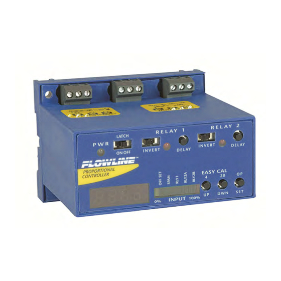
Getting Started Step Four GUIDE TO CONTROLS: Below is a listing and the location of the different components for the controller: 1. Power indicator: This Green LED lights when AC power is ON. 2. Relay indicator: This Red LED will light whenever the controller energizes the relay, in response to the transmitter input and after the time delay. -
Page 9: Configuration (Display)
Getting Started Step Four CONFIGURATION (DISPLAY): The key to configure the LC52 series is to match the 4-20mA operational range of the transmitter, using the OFFSET and SPAN settings to set the 4-20mA operational range on the LC52. OFFSET: Equivalent to the 4 mA set point on the transmitter. Enter the value you would like to see when the LC52 receives 4 mA. -
Page 10: Easycal Calibration
Getting Started Step Four Note: The half digit will appear when scaling between 0.0 and 199.9. If the display is scaled above 199.9, the half digit and the decimal point disappear. If OFFSET = 0 and SPAN = 190, then the display will be scaled as follows: 0.0 to 190.0. ... -
Page 11: Wiring
Wiring Step Five WIRING TO INPUT TERMINAL: Signal input is always through the 24 VDC terminal. The 28 VDC terminal is used as an alternative power supply for three-wire devices. Please note a difference between 2-wire and 3-wire level transmitters and sourcing and sinking modes below. Below is a quick review of wiring the LC52 series to common 4-20 mA transmitters. -
Page 12: Setting Input Polarity
Wiring Step Five SETTING INPUT POLARITY (SOURCING VS. SINKING MODES): The LC52 can be set in one of two modes, sourcing and sinking. The LC52 is shipped from the factory in the sourcing mode. This is compatible with any loop powered transmitter such as the EchoSonic (LU23, LU27, LU28 &... -
Page 13: Relay & Power Terminals
Wiring Step Five RELAY AND POWER TERMINALS Depending on the model selected, there will be either one or two relays. The label for the relay applies for both relays. Each terminal has a Normally Open (NC), Common (C) and Normally Open (NO) terminal. The relay(s) is(are) a single pole, double throw (SPDT) type rated at 250 Volts AC, 10 Amps, 1/4 Hp. -
Page 14: Application Examples
Application Examples Step Six LOW LEVEL ALARM: The goal is to make sure that an operator is notified if the liquid level falls below a certain point. If it does, an alarm will sound, alerting the operator of a low level. A setting for the low level is configured in the controller. -
Page 15: Automatic Fill
Application Examples Step Six AUTOMATIC FILL: This system consists of a tank with a valve controlled by the LC52. At a low set point, the valve opens, filling the tank. At the high set point, the valve closes. Part of a proper fail-safe design for this particular system is that if power is lost to the controller for any reason, the valve filling the tank must close. -
Page 16: Appendix
Appendix Step Seven RELAY LATCH LOGIC – ON VS OFF: Relay 2 can either be an independent relay (high level or low level) with Latch OFF or can be a latching relay (automatic fill or empty) with Latch ON. With Latch OFF, Relay 2 will only Invert OFF Latch OFF Invert ON... -
Page 17: Lockout Function
Appendix Step Seven LOCK OUT FUNCTION: The buttons on the face of the LC52 series can be disengaged or locked out: Function Instructions Lockout Press both delay buttons and the DWN button simultaneously (see below left). This will Buttons lockout all of the buttons and prevent an accidental changing of settings. Unlock Press both delay buttons and the UP button simultaneously (see below right). -
Page 18: Exercise
Exercise Step Eight AUTOMATIC FILL WITH HIGH LEVEL ALARM USING UNITS OF HEIGHT OF LIQUID (INCHES): The following exercise demonstrates inventory control with automatic filling and a high level alarm. usable range is 60 inches of liquid. The pump starts filling at 10 inches of liquid and stops filling at 50 inches of liquid. - Page 19 Exercise Step Eight INVENTORY CONTROL WITH HIGH AND LOW LEVEL ALARMS USING UNITS OF HEIGHT OF LIQUID (INCHES): The following exercise demonstrates inventory control with a high and low level alarm. The usable range is between 16 and 56 inches of liquid. The high level alarm occurs at 50 inches of liquid and the low level alarm occurs at 20"...
-
Page 20: Warranty, Returns & Limitations
PERSON IS AUTHORIZED TO MAKE ANY OTHER WARRANTIES OR REPRESENTATIONS ON BEHALF OF FLOWLINE. This warranty will be interpreted pursuant to the laws of the State of California. If any portion of this warranty is held to be invalid or unenforceable for any reason, such finding will not invalidate any other provision of this warranty.
Need help?
Do you have a question about the DataPoint LC52-1001 and is the answer not in the manual?
Questions and answers