FlowLine DataView LI55 Series Quick Start Manual
Level controller
Hide thumbs
Also See for DataView LI55 Series:
- Instruction manual (104 pages) ,
- Quick start manual (33 pages)

Related Manuals for FlowLine DataView LI55 Series


Summary of Contents for FlowLine DataView LI55 Series
- Page 1 DataView ™ Level Controller LI55 Series Quick Start Flowline, Inc. | 10500 Humbolt Street, Los Alamitos, CA 90720 LIM6000FL_BX11 p 562.598.3015 f 562.431.8507 w flowline.com QS301033 Rev C1...
- Page 2 This product is not recommended for life support applications or applications where malfunctioning could result in personal injury or property loss. Anyone using this product for such applications does so at his/her own risk. Flowline, Inc. shall not be held liable Warning for damages resulting from such improper use.
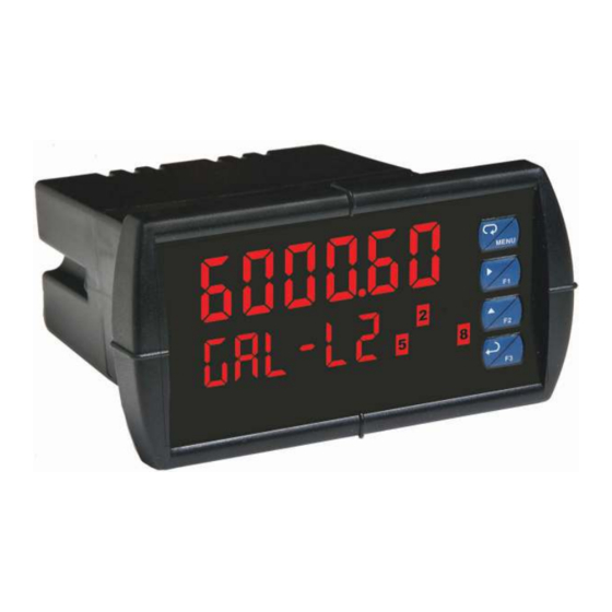
- Page 3 DataView™ LI55 Level Controller Quick Start WE DO YOUR LEVEL BEST™ Thank you for purchasing Dataview™ which is offered in twelve models. The AC or DC powered general purpose level controller displays level in engineering units with one 4-20 mA input, and is available with optional 2 or 4 relays, and an isolated 4-20 mA repeater.
- Page 4 DataView™ LI55 Level Controller Quick Start UNPACKING DATAVIEW™ When unpacking DataView™, inspect for any damage that may have occurred during shipment. Report any damage, missing parts or malfunctions to your distributor. Installation is normally done without opening the enclosure that’s only required when changing the input from current to voltage.
- Page 5 Unscrew the back cover. Slide the back cover about 1 inch to expose the board. Configure the J9 jumper, located behind the power connector for the desired voltage as shown below. J9 Configuration Note: Flowline transmitters require 24 VDC. QS301033 Rev C1...
- Page 6 Unscrew the back cover. Slide the back cover about 1 inch to expose the board. Configure the J4 jumper, located behind the input signal connector for the desired voltage as shown below. Note: Flowline transmitters require 24 VDC. QS301033 Rev C1...
- Page 7 The connector label shows the function of each of the connections, such as POWER, RELAY and SIGNAL. The RJ-45 M-LINK connection is intended for Flowline expansion modules, cables and meters only. Any other use of the RJ-45 connection may damage DataView™ and connected equipment. The different types of connections are explained on the following pages.
- Page 8 The sensor is connected to DataView™ through the six-terminal connector labeled SIGNAL. The COM (common) terminal is the return for the 4-20 mA and the ±10V input signals. Note: Most Flowline level sensors require 2 or 3-wire, 4- 20 mA signal connections.
-
Page 9: Input Signal
DataView™ LI55 Level Controller Quick Start Current Input Connection Below are examples of typical wiring connections for current sensor inputs. There are no switches or jumpers to set for current inputs. Note: The input is protected against overload by a resettable fuse. The display may or may not show a fault condition depending on the nature of the overload. - Page 10 DataView™ LI55 Level Controller Quick Start Voltage Input Connection Below are examples of typical wiring connections for voltage sensor inputs. Note: See the Transmitter Supply Voltage section for optional jumper settings associated with voltage inputs. The input is protected against overload by a resettable fuse.
- Page 11 DataView™ LI55 Level Controller Quick Start Switching Inductive Loads When switching inductive loads, suppressors or snubbers should always be employed as they prevent microprocessor disruption and prolong the life of the relay contacts. Suppression can be obtained with resistor-capacitor (RC) networks assembled by the user or purchased as complete assemblies.
- Page 12 DataView™ LI55 Level Controller Quick Start Repeater Output Connections The repeater may be used to output the 4-20 mA sensor signal to other devices through the connector terminals labeled MA OUT. The 4-20 mA output may be powered internally or from an external power supply. Internal Power - DataView™...
- Page 13 DataView™ LI55 Level Controller Quick Start USING DATAVIEW™ DataView™ is factory calibrated to read 4-20 mA input signals. The calibration is certified to NIST standards. Overview All setup and configuration functions are performed through the front panel interface. After the power and input signal connections have been completed and verified, apply power to the controller.
- Page 14 DataView™ LI55 Level Controller Quick Start Push Buttons DataView™ has four buttons on the right side of the front panel. These are the buttons you will use to set up and configure the controller. Menu Used to enter or exit the configuration mode, view settings or access advanced features.
- Page 15 DataView™ LI55 Level Controller Quick Start CONFIGURING DATAVIEW™ Follow the below six steps to configure DataView™ for your application. Note: Not all models and configurations will require six steps. Set Units of Operation (UnItS) This configures the units of operation and is the value that will appear on the display.
- Page 16 DataView™ LI55 Level Controller Quick Start Entering the Main Menu The Main Menu contains the most commonly used functions including Units SCALE (unitS), Decimal Point (dEc Pt), Scale ( ), Relay (rELAY), Analog Output Aout PASS 1 ) and Password ( ).
- Page 17 DataView™ LI55 Level Controller Quick Start Set Units of Operation (unitS) InCHES, crn, FEEt, rnEtEr DataView™ can display level in distance ( LItErS volume ( ) or custom engineering units. Determine the units of operation that you wish to use, and remember that the units chosen will not only represent the displayed values, but also the settings for the relays and repeater output.
- Page 18 DataView™ LI55 Level Controller Quick Start Set Decimal Point (dEc Pt) The decimal point can be set to as many as five decimal places. Use the decimal point feature to position the decimal point for all displayed values. Placement of the decimal point will influence the displays resolution. Select the best practical scale for indicating level in your application.
- Page 19 DataView™ LI55 Level Controller Quick Start Set SCALE (SCALE) DataView™ displays information about tank contents in engineering units. The controller uses a two point linearization based upon the Empty and Full settings. Note: Although a signal source is not needed to scale DataView™, you must configure the sensor connected to the controller to reflect a 4-20 mA current span between tank empty (4 mA)
- Page 20 DataView™ LI55 Level Controller Quick Start Set SCALE (SCALE) QS301033 Rev C1...
- Page 21 DataView™ LI55 Level Controller Quick Start Set Relays (rELAY) This function sets when the relay(s) will energize ( #) and de-energize #). All settings are based on the units of liquid defined in the Scale section. Note: Never set the relays (SET# or RST#) at the Empty or Full settings.
- Page 22 DataView™ LI55 Level Controller Quick Start Set Relays (rELAY) For high level alarms, SEt# defines the level setting where the relay will turn ON, and rSt# defines the level setting where the relay will turn OFF. Increasing the rSt# setting from the SEt# setting, will increase the relay hysteresis. Note: The rSt# setting should be lower than the SEt# setting.
- Page 23 DataView™ LI55 Level Controller Quick Start Set Relays (rELAY) QS301033 Rev C1...
- Page 24 DataView™ LI55 Level Controller Quick Start Set Analog Output (Aout) With the repeater Analog Output, you can transmit the 4-20 mA signal to another device such as a PLC or SCADA. The repeater can be scaled identically with the 4-20 mA input signal (repeating the input current) or scaled to a smaller span (range of the input current).
- Page 25 DataView™ LI55 Level Controller Quick Start Set Password (PASS 1) The Password menu is used to configure a 6-digit password to prevent unauthorized changes to the controller settings. Note: Record the password for future reference. If appropriate, it may be recorded in the space provided. To configure the Password, follow the below steps.
- Page 26 DataView™ LI55 Level Controller Quick Start Access Password Protection If the controller is password protected, the display will message Locd (locked) when the Menu button is pressed. To access the controller, press ENTER while the Locd message is displayed, enter the correct password, and press ENTER again.
- Page 27 DataView™ LI55 Level Controller Quick Start Disable Password Protection Press ENTER and 000000 will appear. Press Right to move the highlighted digit to the right and Up to increase the Password value. Enter the correct six-digit password. unLoc Press ENTER and Unlocked ( ) will appear.
- Page 28 DataView™ LI55 Level Controller Quick Start RESETTING DATAVIEW™ TO FACTORY DEFAULT To reset the controller to its factory default configuration, follow the below steps. Press and hold MENU for 5 seconds and Setup (SEtuP) will appear. Press and hold MENU again for 3 seconds and Filter (FiLtEr) will appear. Press Up to scroll through the menu options until you reach Diagnostics (diAG).
-
Page 29: Warranty
Flowline for a period, which is equal to the shorter of one year from the date of purchase of such products or two years from the date of manufacture of such products. Flowline's...
Need help?
Do you have a question about the DataView LI55 Series and is the answer not in the manual?
Questions and answers