
Related Manuals for FlowLine Switch-Pro LC90 Series


Summary of Contents for FlowLine Switch-Pro LC90 Series
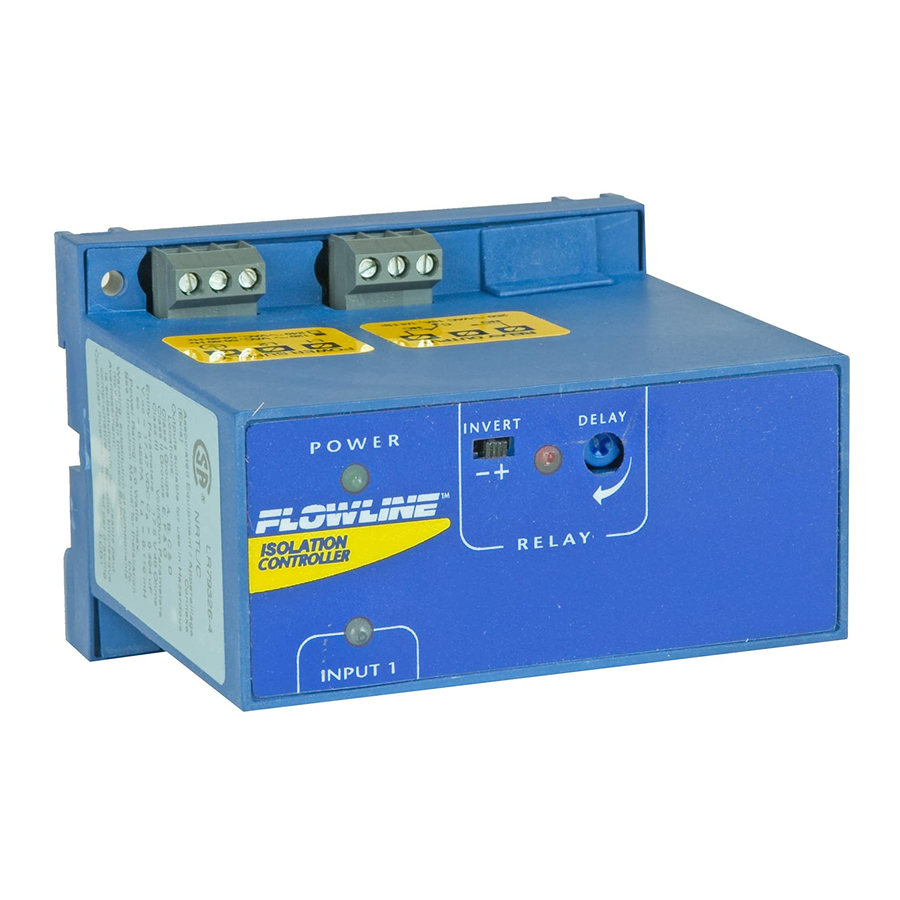
- Page 1 ™ Switch-Pro Remote Level Isolation Controller LC90 and LC92 Series Manual Flowline, Inc. | 10500 Humbolt Street, Los Alamitos, CA 90720 p 562.598.3015 f 562.431.8507 w flowline.com MN301535 Rev A...
-
Page 2: Table Of Contents
Introduction / Table of Contents Step One The LC90 & LC92 Series Controllers are isolation level controllers designed for use with intrinsically safe devices. The controller family is offered in three configurations for pump and valve control. The LC90 Series features a single 10A SPDT relay output and can accept one level sensor as an input. -
Page 3: Specifications / Dimensions
Specifications / Dimensions Step Two SPECIFICATIONS: DIMENSIONS: Supply voltage: 120 / 240 VAC, 50 - 60 Hz. Top View - All Models Consumption: 5 Watts max. Sensor inputs: LC90: (1) level switch LC92: (1, 2 or 3) level switches Sensor supply: 13.5 VDC @ 27 mA per input LED indication: Sensor, relay &... -
Page 4: Control Diagram
Specifications / Dimensions Step Two CONTROL DIAGRAM: CONTROL LABEL: MN301535 Rev A... -
Page 5: Safety Precautions
PRODUCT. This manual includes information on three different models of Remote Isolation Relay Controllers from FLOWLINE: LC90 and LC92 series. Many aspects of installation and use are similar between the three models. Where they differ, the manual will note it. Please refer to the part number on the controller you have purchased as you read. -
Page 6: Make A Fail-Safe System
Such backup systems should use different sensor technologies where possible. While this manual offers some examples and suggestions to help explain the operation of FLOWLINE products, such examples are for information only and are not intended as a complete guide to installing any specific system. -
Page 7: Getting Started
Getting Started Step Four COMPONENTS: Alarm Latching Part Number Power Inputs Function Relays Relays LC90-1001 120 VAC High Level, Low Level or Pump Protection LC90-1001-E 240 VAC Alarm (Relay 1) - High Level, Low Level or LC92-1001 120 VAC Pump Protection Latching (Relay 2) - Automatic Fill, Automatic Empty, High Level, Low LC92-1001-E... -
Page 8: Features Of The Single Input High Or Low Alarm Relay
Getting Started Step Four FEATURES OF A SINGLE INPUT HIGH OR LOW RELAY: Single Input Relays are designed to receive a signal from a single liquid sensor. It turns its internal relay ON or OFF (as set by the invert switch) in response to the presence of liquid, and changes the relay status back again when the sensor is dry. -
Page 9: Features Of The Dual Input Automation Fill/Empty Relay
Getting Started Step Four FEATURES OF A DUAL INPUT AUTOMATIC FILL/EMPTY RELAY: The Dual Input Automatic Fill/Empty Relay (LC92 series only) is designed to receive signals from two liquid sensors. It turns its internal relay ON or OFF (as set by the invert switch) in response to the presence of liquid on both sensors, and changes the relay status back again when both sensors are dry. -
Page 10: Guide To Controls
9. Input terminals: Connect the switch wires to these terminals: Note the polarity: (+) is a 13.5 VDC, 30 mA power supply (connected to the red wire of a FLOWLINE powered level switch), and (-) is the return path from the sensor (connected to the black wire of a FLOWLINE powered level switch). With powered level switches, if the wires are reversed, the sensor will not work. -
Page 11: Wiring
Wiring Step Five CONNECTING SWITCHES TO INPUT TERMINALS: All FLOWLINE intrinsically safe level switches (such as the LU10 series) will be wired with the Red wire to the (+) terminal and the Black wire to the (-) terminal. LED INDICATION: Use LED's located above the input terminals to indicate whether the switch is in a wet or dry state. -
Page 12: Relay And Power Terminals
Wiring Step Five RELAY AND POWER TERMINALS Depending on the model selected, there will be either one or two relays. The label for the relay applies for both relays. Each terminal has a Normally Open (NC), Common (C) and Normally Open (NO) terminal. The relay(s) is(are) a single pole, double throw (SPDT) type rated at 250 Volts AC, 10 Amps, 1/4 Hp. -
Page 13: Installation
Installation Step Six PANEL DIN RAIL MOUNTING: The controller may be mounted by either a back panel using two screws through mounting holes located at the corners of the controller or by snapping the controller on 35 mm DIN Rail. Note: Always install the controller in a location where it does not come into contact with liquid. -
Page 14: Application Exmaples
Application Examples Step Seven LOW LEVEL ALARM: The goal is to make sure that an operator is notified if the liquid level falls below a certain point. If it does, an alarm will sound, alerting the operator of a low level. A level switch must be mounted at the location where the alarm will sound. -
Page 15: Pump Protection
Application Examples Step Seven PUMP PROTECTION: The key here is to install a level switch just above the outlet to the pump. As long as the switch is Wet, the pump can operate. If the switch ever becomes Dry, the relay will open preventing the pump from running. -
Page 16: Automatic Empty
Application Examples Step Seven AUTOMATIC EMPTY: Similar system logic can be used for an automatic empty operation. In this example, we will use a pump to empty a tank. The system still consists of a tank with a high level sensor, a low level sensor, and a pump that is controlled by the controller. -
Page 17: Appendix
Appendix Step Eight RELAY LOGIC – AUTOMATIC FILLING AND EMPTYING Latching relay will only switch when both level switches are in the same state. One Switch Dry, One Wet Both Switches Wet Both Switches Dry In this state, the relay will never In this state, the relay will typically In this state, the relay will typically switch, regardless if this is an Auto... -
Page 18: Latch - On Vs Off
Appendix Step Eight LATCH - ON VS OFF: The relay can either be an independent relay (high level, low level or pump protection) with Latch OFF or can be a latching relay (automatic fill or empty) with Latch ON. With Latch OFF, the relay will only Invert OFF Latch OFF Invert ON... -
Page 19: Troubleshooting
Appendix Step Eight TROUBLESHOOTING PROBLEM SOLUTION Relay switches only from input A Latch is turned OFF. Flip the latch switch to turn ON. (ignores input B) Level reaches alarm ON, but relay First, check to make sure the input LED is ON. If not, check wiring to is OFF. -
Page 20: Warranty
PERSON IS AUTHORIZED TO MAKE ANY OTHER WARRANTIES OR REPRESENTATIONS ON BEHALF OF FLOWLINE. This warranty will be interpreted pursuant to the laws of the State of California. If any portion of this warranty is held to be invalid or unenforceable for any reason, such finding will not invalidate any other provision of this warranty.
Need help?
Do you have a question about the Switch-Pro LC90 Series and is the answer not in the manual?
Questions and answers