Table of Contents
Advertisement
Quick Links
Advertisement
Chapters
Table of Contents
Troubleshooting

Related Manuals for Parker 590+ DRV


Summary of Contents for Parker 590+ DRV
- Page 1 590+ DRV Frame 1, 2, 3, 4, 5, 6 & 7 HA470388U003 Issue 2 Product Manual...
- Page 3 2011 Parker SSD Drives, a division of Parker Hannifin Ltd. All rights strictly reserved. No part of this document may be stored in a retrieval system, or transmitted in any form or by any means to persons not employed by a Parker SSD Drives company without written permission from Parker SSD Drives, a division of Parker Hannifin Ltd .
- Page 4 Parker or its subsidiaries or authorized distributors. To the extent that Parker or its subsidiaries or authorized distributors provide component or system options based upon data or specifications provided by the user, the user is responsible for determining that such data and specifications are suitable and sufficient for all applications and reasonably foreseeable uses of the components or systems.
-
Page 5: Intended Users
Cont. iii Requirements IMPORTANT Please read this information BEFORE installing the equipment. Intended Users This manual is to be made available to all persons who are required to install, configure or service equipment described herein, or any other associated operation. The information given is intended to highlight safety issues, and to enable the user to obtain maximum benefit from the equipment. - Page 6 Cont. iv Product Warnings Caution Caution Earth/Ground Risk of electric shock Refer to documentation Protective Conductor Terminal Hazards DANGER! - Ignoring the following may result in injury 1. This equipment can endanger life by exposure to rotating 5. For measurements use only a meter to IEC 61010 (CAT III or higher). machinery and high voltages.
- Page 7 Cont. v WARNING! - Ignoring the following may result in injury or damage to equipment SAFETY Where there is conflict between EMC and Safety requirements, personnel safety shall always take precedence. • Never perform high voltage resistance checks on the wiring without •...
- Page 8 Cont. vi CAUTION! APPLICATION RISK • The specifications, processes and circuitry described herein are for guidance only and may need to be adapted to the user’s specific application. We can not guarantee the suitability of the equipment described in this Manual for individual applications. •...
-
Page 9: Table Of Contents
Cont. vii C o n t e n t s Design Recommendations DC590+ DRV DC DIGITAL DRIVE Mounting Instructions................3-2 • Intended Users Product Dimensions • Ventilation and Cooling Requirements Application Area Line Reactor/Isolation Transformer • Personnel Electrical Installation ................3-5 Hazards....................4 EMC Wiring Details CHAPTER 1 GETTING STARTED... - Page 10 Cont. viii Installation Drawings .................3-64 Field Control Connection Diagrams................3-77 • Set-Up Notes • Field Weakening CHAPTER 4 CALIBRATION AND START-UP • Standby Field Introduction ..................4-1 Initial Checks ..................4-1 CHAPTER 6 THE KEYPAD • Recommended Tools Connecting the 6911 Keypad ...............6-1 Check Motor Control Key Definitions Check Supply...
- Page 11 What are the European Directives? Saving Your Application Data CE Marking for the Low Voltage Directive (LVD) 2006/95/EC Returning the Unit to Parker SSD Drives CE Marking for the EMC Directive 2004/108/EC Disposal United States of America & Canada ............B-4...
- Page 12 Cont. x • • Field Wiring Terminal Markings ANALOG INPUTS D-21 • • Power and Control Field Wiring Terminals ANALOG OUTPUTS D-23 • • Field Grounding Terminals AUTOTUNE D-24 • • Field Terminal Kits AUX I/O D-26 • • Recommended Wire Sizes CALIBRATION D-27 •...
- Page 13 Cont. xi • • RAMPS D-102 Terminal Information - Power (Frames 6 & 7) E-14 • • SELECT D-108 Terminal Information – Control Board E-16 • • SEQUENCING D-109 Terminal Information - Option Boards E-21 • • SETPOINT SUM D-112 Wiring Requirements for EMC Compliance E-22 •...
-
Page 15: Getting Started
Getting Started Chapter 1 A few things you should do when you first receive the unit. About this Manual Equipment Inspection and Storage • • • Packaging and Lifting Details How the Manual is Organised • • Initial Steps... - Page 16 DC590+ DRV DC Digital Drive...
-
Page 17: About This Manual
Getting Started About this Manual This manual is intended for use by the installer, user and programmer of the DC590+ DRV DC Digital Drive. It assumes a reasonable level of understanding in these three disciplines. NOTE Please read all Safety Information before proceeding with the installation and operation of this unit. Enter the “Model No”... -
Page 18: Equipment Inspection And Storage
Getting Started Operation Know your operator: • how is it to be operated, local and/or remote? • what level of user is going to operate the unit? • decide on the best menu level for the Keypad (where supplied) Programming (Keypad or suitable PC programming tool only) Know your application: •... -
Page 19: Product Overview
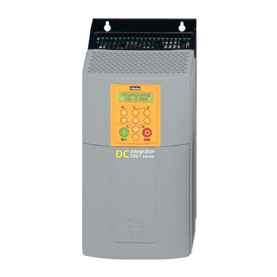
Product Overview Chapter 2 An introduction to the DC590+ DRV range of products, and a quick look at the Keypad and available plug-in Options. How it Works Product Range Control Features Product Identification Understanding the Product Code Component Identification • Catalog Number ( North America) Keypads •... - Page 20 DC590+ DRV Series DC Digital Drive...
-
Page 21: How It Works
Product Overview How it Works NOTE Refer to Chapter 5: “Control Loops” for a more detailed speed increase explanation. due to field weakening In very simple terms, the drive controls the dc motor with the use of Armature Control Loops - an inner Current Loop and an outer Speed Loop. These Voltage 200V armature voltage control loops can be seen in the Application Block Diagram. -
Page 22: Control Features
Product Overview Control Features Control Control Circuits Fully isolated from power circuit (SELV) • Fully controlled 3-phase thyristor bridge Output Control • Microprocessor implemented phase control extended firing range • For use on 50 or 60Hz supplies with a frequency compliance range of 45 to 65Hz •... -
Page 23: Understanding The Product Code
Product Overview Understanding the Product Code Catalog Number ( North America) The unit is fully identified using an alphanumeric code which records how the drive was calibrated and its various settings when despatched from the factory. The Product Code appears as the “Cat No”. Each block of the Product Code is identified as below: Catalog Number (North America) Block No. -
Page 24: Model Number (Europe)
Product Overview Model Number (Europe) The unit is fully identified using an alphanumeric code which records how the drive was calibrated, its various settings when despatched from the factory, and the country of origin. The Product Code appears as the “Model No”. -
Page 25: Model Number (Europe - Legacy Numbers)
500 to 690V (±10%) 50/60Hz (Frame 7 only) XXXX 4 digits describing the mechanical package including livery and mechanical package style: First two digits (on the left) Livery Standard Parker SSD Livery Distributor Livery 01-04 and 06-99 Defined customer liveries TBA Third digit... - Page 26 Product Overview Model Number (Europe) Block No. Variable Description Two characters specifying the user interface language: UK = English SP = Spanish * FR = French IT = Italian * GR = German * * refer to Customer Services Up to three characters specifying the feedback option (one must be fitted): ARM = Armature Voltage ENP = Encoder (plastic fibre-optic) AN = Analog Tacho...
-
Page 27: Door Assembly Product Code
590PXD : Fits Frame 3 and H units XXXX 4 digits describing the mechanical package including livery and mechanical package style: First two digits (on the left) Livery Standard Parker SSD Livery Distributor Livery 01-04 and 06-99 Defined customer liveries TBA Third digit... -
Page 28: Product Range
Product Overview Product Range The DC590+ DRV contains the DC590+ controller, a contactor and ac supply fusing. An optional control transformer, motor blower and dynamic brake are also available. System Design The drive is designed for use in a suitable enclosure, with associated control equipment. The unit accepts a variety of standard three-phase ac supply voltages depending upon the model, and is suitable for the powering of DC shunt field and permanent magnet motors, providing controlled dc output voltage and current for armature and field. -
Page 29: Product Identification
Product Overview Product Identification Indicates a panel-mounted DRV Output Currents (armature): Frame H Frame 1 Frame 2 Frame 3 Frame 4 Frame 5 Frame 6 206A 360A 1000A 1250A 1050A (Europe only) 180A 380A 1580A 1250A 1200A 246A 425A 1200A 1660A 1450A 270A... -
Page 30: Component Identification
2-10 Product Overview Component Identification DC590+ DRV DC Digital Drive (Frames 1 & 2) Main drive assembly Front View (with items removed) Terminal cover Terminal cover retaining screw Blank cover (part number: LA389836U001) 6901 Keypad COMMS technology box (optional) Speed feedback technology card (optional) Gland plate Power terminal shield Power terminals... -
Page 31: Door Assembly (Frames 3, 4, 5 & 7)
2-11 Product Overview 590+ Door Assembly (Frames 3, 4, 5 & 7) Main door assembly Front View (with items removed) Terminal cover Terminal cover retaining screw Blank cover (part number: LA389836U001) 6901 Keypad COMMS technology box (optional) Speed feedback technology card (optional) Control terminals Keypad port RS232 programming port (P3) -
Page 32: Dc590+ Drive (Frame 3)
2-12 Product Overview DC590+ Drive (Frame 3) Main drive assembly Door assembly Field wiring terminals Busbars - main power input Busbars - main power output IP20 Top Cover IP20 Fan Housing (where fitted) Door Assembly Product Code 590PXD/..DC590+ DRV Series DC Digital Drive... -
Page 33: Dc590+ Drive (Frames 4 & 5)
2-13 Product Overview DC590+ Drive (Frames 4 & 5) Main drive assembly Standard door assembly Motor field terminals Busbars - main power input Frame 4 Frame 5 Busbars - main power output Auxiliary supply, contactor and motor thermistor terminals Frame 4 External vent (where fitted) Contactor Control Select Frame 5 External vent (where fitted) Door... -
Page 34: Drive (Frame 6)
2-14 Product Overview 590+ Drive (Frame 6) Phase assemblies - L1, L2, L3 Fishplate Control Panel Assembly Front Cover Standard Door Assembly Field Controller Busbars - main power input Busbars - main power output DC590+ DRV Series DC Digital Drive... -
Page 35: Dc590+ Product (Frame 7)
2-15 Product Overview DC590+ Product (Frame 7) Removable Lifting Brackets (4 off) Keyhole Mounting Slots (8 off for 4Q Regenerative) (6 off for 2Q Non-Regenerative) 590+ SERIES EUROTHERM DRIVES Armature terminals are Auxiliary fitted to right hand side Power Power of the drive but can Control Main... -
Page 36: Keypads
2-16 Product Overview Keypads The drive is fitted with the 6901 Keypad. It provides Local control of the drive, monitoring and complete access for application programming. For example, you can start and stop the motor, check on diagnostic information, and change parameters values on the drive. The keypad fits to the front of the drive, however, you can also remote-mount the keypad up to 3 metres away. -
Page 37: Installing The Drive
Installing the Drive Chapter 3 This chapter describes the mechanical and electrical installation of the drive and associated equipment. Mechanical Installation • Remote Mounting the Keypad • Dynamic Braking Option • Design Recommendations • Blower Motor Protector Option Mounting Instructions •... - Page 38 DC590+ DRV Series DC Digital Drive...
-
Page 39: Mechanical Installation
If the transformer supplies other equipment, verify that the load is balanced on all legs and is rated for the total load. Line Reactor When several drives are connected to an isolation transformer, Parker SSD Drives recommends adding a line reactor for each drive. This prevents SCR line notching from affecting other drives and control equipment. -
Page 40: Mounting Instructions
Installing the Drive Mounting Instructions The DC590+ DRV Digital drive is designed to mount directly onto a vertical, flat surface. All models are designed with the incoming three-phase supply connections the motor connections at the bottom. Units rated 125 through 500 HP have terminals for the motor field connections and optional motor blower connections mounted on the left. -
Page 41: Product Dimensions
Installing the Drive Product Dimensions Refer to “Installation Drawings”, page 3-51 for further information. Ventilation and Cooling Requirements The drive must be able to dissipate the heat it generates during use. Therefore, mount the unit vertically so that a free flow of cool air can pass through the drive. -
Page 42: Line Reactor/Isolation Transformer
Installing the Drive Line Reactor/Isolation Transformer If no isolation transformer is used, we recommend that you always use the specified line reactor with the drive to provide a known supply impedance for effective operation of the thyristor transient suppression circuits. At least 2% line impedance should be provided in the supply side of the drive. -
Page 43: Electrical Installation
To avoid damaging the drive NEVER carry out high voltage resistance or dielectric strength tests without first completely disconnecting the drive from the circuit being tested. Caution Incorrect wiring is a common cause of start up problems. If you have questions about wiring procedures, contact Parker SSD Drives Product Support. DC590+ DRV Series DC Digital Drive... -
Page 44: Emc Wiring Details
If the drive is to be operating in a regenerating mode for extended periods acting as a load generator for another machine, it is advisable to fit additional protection in the armature circuit. A dc fuse or high speed circuit breaker will provide this protection. If in doubt, contact Parker SSD Drives. - Page 45 Installing the Drive Cable Gland Requirements (Frame 1) Use a metal gland to connect to the cubicle backplate, near the VSD (variable speed drive). It must be capable of securing a 360 degree screened connection to give EMC compliance. A 360 degree screened connection can be achieved as shown. We suggest a rubber grommet should be fitted on holes where a cable gland is not used.
- Page 46 Installing the Drive (D3) (D4) (D5) (D6) FL1 FL2 (D1) (D2) (D7) (D8) Control Terminals Control Terminals TH1 TH2 TH1 TH2 Control Terminals F+ F- TH1 TH2 FL1 FL2 F+ F- L1 L2 L3 A+ A- L1 L2 L3 A+ A- L1 L2 L3 A+ A- Frame 1 Frame 2...
- Page 47 Installing the Drive Control Terminals FL1 FL2 F+ F- TH1 TH2 L1 L2 L3 A+ A- Frame 4 4 (N) Control Terminals Note : On Frame 5 units the left hand unit is fitted with two A+ terminals, and Earthing points on the right hand unit has rear of drive two A- terminals...
-
Page 48: Wiring Instructions - Minimum Connections
The following sections describe connections shown in the Connection Diagrams located at the end of this chapter. Power Wiring If you need electrical terminals for motor and supply connections, Parker SSD Drives has UL-approved crimp terminal kits available in the following armature current ranges: Amps Terminal Kit Catalog No. - Page 49 NOTE If in doubt about connection of the DC motor to the drive, check with Parker SSD Drives. Connect the motor armature to terminals A+ and A-. To comply with national and local electrical codes, external DC overload protection must be provided.
- Page 50 The enable input C5 must be True (24V) for the drive to run. If using the Dynamic Braking Option, remove the jumper across control terminals C5, C9 on the drive. The braking current rating of the contactor is 150% of armature current. Contact Parker SSD Drives for a range of resistors meeting NEMA ICS 3- 302.62.
- Page 51 3-13 Installing the Drive External Field Supply (FL1, FL2) WARNING Verify that power is disconnected before proceeding. This connection is not available on Frame 1 DRVs. Frame 7 DRVs always require an external field supply. If this option to convert to using an external ac field is not required, do not connect to these terminals. Occasionally, motors require field voltages greater or smaller than can be supplied by the main L1, L2 and L3 supply.
- Page 52 3-14 Installing the Drive PLG1 to Power Board PLG2 to Power Board PLG3 to Power Board Motor Vent Fan Circuit Breaker External Field Selector Plug AUX. L N 3 4 TH1 TH2 CONT. FL1 FL2 F+ M2 M3 Terminal Board Field Bridge Field Bridge FL1 FL2...
-
Page 53: Control Wiring
3-15 Installing the Drive Control Wiring MOT/THERM LINK IF +100 LINK IF -100 NOT USED NOT USED NORMALLY OPEN These NORMALLY CONTACT OPEN terminals POTENTIOMETER SWITCH ON MAIN vary in USED AS CONTACTOR location SETPOINT RAMP EMERGENCY INPUT Refer to STOP RELAY Terminal Locations... - Page 54 3-16 Installing the Drive Enable (C5) ENABLE On Frames 1 and 2, terminal C5 (ENABLE) is connected to terminal C9 (+24V). Internally, terminal C5 is connected in series with a normally open auxiliary contact on the DRV main contactor. On Frames 3 and larger, terminal C5 (ENABLE) is connected to terminal C9 (+24V) internally through a normally-opened auxiliary contact on the DRV main contactor.
- Page 55 3-17 Installing the Drive Asymmetric Current Limits (A5, A6, B3, B4, C6) ANIN 5 For asymmetric current limits, connect terminal C6 (CURRENT CLAMP SELECT) to C9 (24VDC), which sets parameter BIPOLAR CLAMPS to TRUE. This lets terminal A5 control the negative current clamp and terminal A6 control the positive current clamp. Connect terminal A5 (ANALOG INPUT 4) to terminal B4 (-10 VDC REFERENCE) and connect terminal A6 (ANALOG INPUT 5) to terminal B3 (+10 VDC REFERENCE).
-
Page 56: Additional Control Connections
3-18 Installing the Drive Additional Control Connections NOTE Appendix E: "Technical Specifications", Terminal Information - Control Board lists details for all control terminals. Speed Setpoint No. 1 (A2) ANIN 1 This is another choice of input for the speed setpoint. It bypasses the "Setpoint Ramp Generator" used by terminal A4 (ANIN3), and should be used if direct control is required. -
Page 57: Motor Field Connections
3-19 Installing the Drive AT ZERO SPEED – When the drive speed feedback drops below the zero speed threshold, terminal B5 will output 24 VDC. DRIVE HEALTY – When there are no software or hardware alarms and terminal C3 (RUN) is ON or when C3 is OFF, terminal B6 will output 24 VDC. - Page 58 3-20 Installing the Drive FRAME 2 : Terminal Board - PCB Reference AH470330 The position of the jumper selects the board to use either an internal or external motor field. PLG1 to Power Board PLG2 to Power Board PLG3 to Power Board Motor Vent Fan Circuit Breaker External Field Selector Plug AUX.
- Page 59 3-21 Installing the Drive FRAME 3 : Power Board - PCB Reference AH385851 This power board can be altered for use with either an internal or external motor field supply: Internal Motor Field (default for this board) Terminals D3 and D4, the motor field outputs, are energised when the 3-phase supply to L1/L2/L3 is energised and the internal motor field is used. Terminals D1 and D2 are not energised.
- Page 60 3-22 Installing the Drive The external field supply can now be connected and power restored to the drive. FRAMES 4 & 5 : Power Board – PCB Reference AH466701 This power board can be altered for use with either an internal or external motor field supply: Internal Motor Field (default for this board) Terminals F+ and F-, the motor field outputs, are energised when the 3-phase supply to L1/L2/L3 is energised and the internal motor field is used.
-
Page 61: Dc Contactor - External Va Sensing
3-23 Installing the Drive DC Contactor - External Va Sensing Connections are provided for external armature voltage sensing (at the motor) for when a dc contactor is used between the drive and motor. Power Board - PCB Reference 385851 (Frame 3) DC590+ DRV Series DC Digital Drive... -
Page 62: Power Board - Pcb Reference 466701 (Frames 4 & 5)
3-24 Installing the Drive Power Board – PCB Reference 466701 (Frames 4 & 5) EX A- EX A+ F+ F- FL1 FL2 busbar busbar contactor terminals Fuses - only necessary for 3 & 4 (TB2) local leads longer than 3 metres Locate fuses close to signal source when fitted DC590+ DRV Series DC Digital Drive... -
Page 63: External Connections (Frames 6 & 7)
3-25 Installing the Drive External Connections (Frames 6 & 7) Motor field supply and and output terminals plus external armature voltage sense MVA+ MVA- busbar busbar contactor power Fuses - only necessary for control local leads longer than 3 metres terminals N &... -
Page 64: Power Board Circuit Descriptions
3-26 Installing the Drive Power Board Circuit Descriptions AH470280U001, U002, U003, U004 (Frame 1) (2 Quad and 4 Quad) Power supplies for the controller are generated from the CONN 4 CONN 26 single phase auxiliary supply via a Switched Mode Power (to control board) (to heatsink thermistor) Supply. - Page 65 3-27 Installing the Drive TERMINAL BOARD POWER BOARD CONN 1 (to power board) reverse bridge field fuses armature voltage feedback forward bridge aux. supply fuse armature heatsink fan current feedback heatsink heatsink overtemperature thermistor Figure 3- 8 Terminal Board - AH466407 +24V supply 3 phase present...
-
Page 66: Ah470330 (Frame 2)
3-28 Installing the Drive AH470330 (Frame 2) (2 Quad and 4 Quad) Power supplies for the controller are generated CONN 29 from the single phase auxiliary supply via a (to control board) Switched Mode Power Supply. The incoming supply is directly rectified to provide a high test points voltage dc power rail. - Page 67 3-29 Installing the Drive POWER TER M INA LS suppress ion components suppression reverse bridge reverse bridge components forward bridge forward bridge armature voltage feedback M C coil armature current feedback TERM INAL BOARD coding & coding phas e phas e rotation MC A ux rotation 3 phas e...
-
Page 68: Ah385851U002, U003, U004, U005 (Frame 3)
3-30 Installing the Drive AH385851U002, U003, U004, U005 (Frame 3) (590+ - 4 Quad, 591+ - 2 Quad; Low and High Volt) Power supplies for the controller are generated from the single phase auxiliary supply via a switched mode power supply. - Page 69 3-31 Installing the Drive Heatsink Cooling Fan Connections When fitted, these fans are connected on the power board to FAN LIVE (F27), FAN NEUTRAL (F24) and FAN COMMON (F23) as described below: • A single fan must be matched to the auxiliary supply and connected to F27 and F24. •...
- Page 70 3-32 Installing the Drive POWER BOARD motor voltage feedback thermostat EXA+ EXA- ACCT PRESENT VA FEEDBACK -100 current feedback (F15) (F8) 3 PHASE PRESENT HIGH VOLTAGE CODING INTERFACE PHASE ROTATION GREY BROWN (F6) FL1 (F15) YELLOW FL2 (F9) VIOLET SUPPRESSION ORANGE CIRCUITS (F7)
- Page 71 3-33 Installing the Drive (F-) (F+) +24V (F13) (F17) (F14) TRANSFORMER (TH1) (TH10) (TH3) (TH12) (TH5) (TH8) (TH7) (TH4) (TH9) (TH6) (TH11) (TH2) Figure 3- 14 590 Power Board EX A+ 4 Quad (AH385851U002, U005) - (Frame 3) EX A- DC590+ DRV Series DC Digital Drive...
- Page 72 3-34 Installing the Drive POWER BOARD motor voltage feedback TH12 TH10 TH11 thermostat EXA+ EXA- ACCT PRESENT VA FEEDBACK -100 current feedback (F15) (F8) 3 PHASE PRESENT HIGH VOLTAGE CODING INTERFACE PHASE ROTATION GREY BROWN (F6) FL1 (F15) FL2 (F9) VIOLET YELLOW SUPPRESSION...
-
Page 73: Ah466701U001, U002, U003 (Frames 4 & 5)
3-35 Installing the Drive AH466701U001, U002, U003 (Frames 4 & 5) 590+ 4 Quad and 591+ 2 Quad; Low, Medium and High Volt Power supplies for the controller are generated from the single phase auxiliary supply via a Switched Mode Power Supply. The incoming supply is directly rectified to provide a high voltage dc power rail. - Page 74 3-36 Installing the Drive G1 K1 TH12 TH10 TRIGGER BOARD TH10 TH12 AH466703U002 TH11 CONN8 CONN9 CONN10 TH10 TH12 3 PHASE PRESENT CODING & 3 PHASE PRESENT CODING ACCT. PRESENT CURRENT FEEDBACK EX A+ A+ red ARMATURE ARMATURE VOLTAGE CONN4 resistors VOLTAGE FEEDBACK...
- Page 75 3-37 Installing the Drive G1 K1 CONN8 CONN9 CONN10 3 PHASE PRESENT CODING & 3 PHASE PRESENT CODING ACCT. PRESENT CURRENT FEEDBACK EX A+ A+ red ARMATURE ARMATURE VOLTAGE VOLTAGE CONN4 resistors FEEDBACK FEEDBACK A- gray 50 WAY EX A- CONTROL CABLE yellow...
-
Page 76: Ah469419 (Frame 6)
3-38 Installing the Drive AH469419 (Frame 6) Power supplies for the controller are generated from the single phase auxiliary supply via a Switched Mode Power Supply. The incoming supply is directly rectified to provide a high voltage dc power rail. A high voltage transistor switches this rail onto the primary of a high frequency transformer, the output of which is rectified and smoothed to provide the dc power supply rails. -
Page 77: Ah466001U001, U101 (Frame 7)
3-39 Installing the Drive AH466001U001, U101 (Frame 7) (590+ - 4 Quad and 591+ - 2 Quad; Low and High Volt) Power supplies for the controller are generated from the single phase auxiliary supply via a Switched Mode Power Supply. The incoming supply is directly rectified to provide a high voltage dc power rail. - Page 78 3-40 Installing the Drive G1 K1 SUPRESSION SUPRESSION SUPRESSION 2 WAY TRIGGER TRIGGER TRIGGER CONNECTOR TH1 & 4 TH3 & 6 TH5 & 2 UPPER FS7 FS8 FS9 HEAT ACCT. PRESENT SINK LINE SUPP. ACCT. FIELD ASSEMBLY EXT.A- EXT.A+ FIELD AC SUPPLY LOWER HEAT...
- Page 79 3-41 Installing the Drive G1 K1 TH10 TH12 BLANK BLANK BLANK TRIGGER TRIGGER TRIGGER TH4 & 7 TH6 & 9 TH2 & 11 TH1 & 10 TH3 & 12 TH5 & 8 TH11 TRIGGER TRIGGER TRIGGER BLANK BLANK BLANK FS7 FS8 FS9 ACCT.
-
Page 80: Optional Equipment
3-42 Installing the Drive Optional Equipment Remote Mounting the Keypad The 6052 Mounting Kit is required to remote-mount a 6901 or 6911 Keypad. An enclosure rating of IP54 is achieved for the remote Keypad when correctly mounted using the 6052 Mounting Kit. You can also replace a Keypad for a PC running DSELite (or other suitable PC programming tool) in all of the options above. - Page 81 3-43 Installing the Drive Assembly Procedure Figure 3-21 Mounting Dimensions for the Remote-Mounted Keypad DC590+ DRV Series DC Digital Drive...
-
Page 82: Dynamic Braking Option
This combination, in accordance with NEMA ICS 3-302.62, will provide 150% instantaneous braking torque from base speed for each power range, with 2 times motor inertia and 3 stops per hour. Please contact Parker SSD Drives for more information. Blower Motor Protector Option This option uses a manual motor circuit controller to provide motor overload and branch circuit protection for a single or three phase AC blower motor. -
Page 83: Speed Feedback Options
3-45 Installing the Drive Speed Feedback Options The DC590+ DRV Digital drive accepts the following types of speed feedback signals: • armature voltage feedback ( see below) • analog AC or DC tachometer generator feedback • wire-ended electrical encoder feedback •... - Page 84 3-46 Installing the Drive Feedback Receiver Board Installation Each speed feedback board mounts on the lower left portion of the control board as shown above. Terminal assignments for each option board are listed in Appendix E and in the documentation shipped with the boards. To install the receiver board on the drive control board: 1.
- Page 85 3-47 Installing the Drive Analog Tacho Calibration Option Board WARNING Do not fit this Option Board with the drive powered-up This product may be fitted with a new version of the Analog Tacho Calibration Option Board. ORIGINAL The original option has Part Number AH385870U001 and is configured by setting its two 10-position slide switches and two 2-position slide switches.
- Page 86 The maximum allowable encoder frequency is 100kHz, thus with a standard 1000 lines per revolution encoder the motor speed cannot exceed 6000 rpm. For specification and connection information refer to Parker SSD Drives or the Technical Manual supplied with the Encoder. DC590+ DRV Series DC Digital Drive...
- Page 87 3-49 Installing the Drive Microtachs (F1, C1, C9) A Microtach can be connected to provide speed feedback via the Microtach Option Board using the international standard “ST” fibre optic system. This board provides terminal F1. F1 is the fibre optic 5701/5901 MICROTACH receiver input socket.
-
Page 88: Communications Technology Options
COMMS Option Technology Box The option allows the DC590+ DRV Drive to be controlled as part of a system. COMMS The system can also comprise other Parker SSD Drives products such as the 605 and 584SV Speed Option Inverters, or any other equipment using the same protocol. -
Page 89: Frame 6: Assembly And Installation
3-51 Installing the Drive Frame 6: Assembly and Installation The DC590+ Frame 6 is a high power DC drive and is supplied as a kit of parts ready for mounting onto the back panel of an enclosure. The drive can be arranged to have the AC input terminals either at the top or the bottom of the drive. - Page 90 It is necessary to remove this heat by fitting fans in the roof of the enclosure. A suitable fan assembly is available from Parker SSD Drives, part number LA466038. The assembly contains two fans that can be connected in parallel or series to achieve 115Vac or 230Vac operation.
-
Page 91: Assembly
3-53 Installing the Drive Assembly Caution Use proper lifting techniques when lifting and moving the unit. 1 Phase assemblies - L1, L2, L3 3 Control Panel Assembly 2 Fishplate 4 Front Cover DC590+ DRV Series DC Digital Drive... - Page 92 3-54 Installing the Drive The drive is assembled in the following order: 1. Mount the phase assemblies onto the backplate 2. Inter-connect the phase assemblies using the fishplates 3. Secure the control panel assembly onto the phase assemblies 4. Connect all signal cables and ribbons 5.
- Page 93 3-55 Installing the Drive Moving the AC Supply Terminals The AC supply terminals - L1, L2 & L3 - can be made available at the top or bottom of the drive. The factory- delivered drive has the AC terminals in the lower position. It only takes a few minutes to rotate the AC terminals to the upper position.
- Page 94 3-56 Installing the Drive Mounting the Phase Assemblies The three phase assemblies are mounted vertically onto a solid, flat, vertical backplate inside the cubicle, with the fans at the bottom. Temporary Hanging: A temporary hanging point is provided to hang the unit on before securing the phase assembly to the backplate at the four corners.
- Page 95 3-57 Installing the Drive Backplate Drilling Procedure Cover any units already mounted to the backplate to protect them from stray metal filings before drilling the mounting holes. Refer to the diagram on the previous page and drill the mounting holes into the backplate. The holes must be positioned accurately. For each phase assembly: •...
- Page 96 3-58 Installing the Drive Temporary Hanging Bolts IMPORTANT We strongly recommend using the temporary mounting hole to hang the unit on the backplate - the phase assemblies are heavy. This mounting point is not intended for permanent fixing. • Fit M10 x 20mm long bolts to the three "temporary hanging" mounting holes. Screw them in part of the way so that you can still see 12mm of thread.
- Page 97 3-59 Installing the Drive Tightening the Drive When all the bolts are in place, tighten them to the following torques: • mounting bolts (4 per phase assembly) : 32Nm (23.6 ft.lbf) • fishplate bolts : 32Nm (23.6 ft.lbf) Reminder : Remove the "temporary hanging" bolts. Fitting the Control Panel Assembly Fit the M6 x 16mm support screw assemblies [screw, single coil spring washer &...
- Page 98 3-60 Installing the Drive Terminal Connections The control panel assembly has connectors for each phase assembly. These are secured in such a way that the cables will only reach the correct terminals set: 1, 2, 3 or 4. NOTE Terminal sets 3 & 4 feature similar 6-way connectors, however one is a male connector and the other a female, so they can't be fitted incorrectly.
-
Page 99: Electrical Installation
3-61 Installing the Drive Electrical Installation IMPORTANT: Please read the Safety Information on page Cont. 3 & 4 before proceeding. Refer to Electrical Installation, page 3-5 to continue with the drive installation. Auxiliary Plug Field Plug (this plug has two retaining screws) Power Connections... -
Page 100: Frame 7: Additional Information
3-62 Installing the Drive Frame 7: Additional Information Removing the Cover (Frame 7) The cover is manufactured from sheet metal and weighs:- • 2Q Non-Regenerative = 10kg (22 lbs) • 4Q Regenerative = 15kg (33 lbs) To remove the cover use a flat headed screwdriver to undo the two screws at the base of the cover. Now lift the cover base outwards and upwards, once the cover has been raised two centimetres it can now be removed. - Page 101 3-63 Installing the Drive Installing the Fan (Frame 7) Refer to Appendix E: “Technical Specifications” - Cooling Fans. The fan unit supplied should be installed on the cubicle, with or without ducting (refer to the Installation Drawing). The drive is force-cooled using the fan units supplied with the drive.
-
Page 102: Installation Drawings
3-64 Installing the Drive Installation Drawings Figure 3-23 Frame 1 : 7.5 HP, 20 HP (15A, 35A) Stack Assembly DC590+ DRV Series DC Digital Drive... - Page 103 3-65 Installing the Drive Figure 3-24 Frame 2 : 30-100HP (55A-165A) Stack Assembly DC590+ DRV Series DC Digital Drive...
- Page 104 3-66 Installing the Drive Figure 3-25 Frame 3 DRV : 125 & 150 HP with 3 Pole Contactor (206A-243A) DC590+ DRV Series DC Digital Drive...
- Page 105 3-67 Installing the Drive Figure 3-26 Frame 3 DRV : 125 & 150 HP with AC Contactor (206A-243A) DC590+ DRV Series DC Digital Drive...
- Page 106 3-68 Installing the Drive Figure 3-27 Frame 4 DRV with 3 Pole DC Contactor : 200HP (360A) DC590+ DRV Series DC Digital Drive...
- Page 107 3-69 Installing the Drive Figure 3-28 Frame 4 DRV with 3 Pole DC Contactor : 250 - 300HP (425A-490A) DC590+ DRV Series DC Digital Drive...
- Page 108 3-70 Installing the Drive Figure 3-29 Frame 4 DRV with 1 Pole DC Contactor : 300-500HP (490A-815A) DC590+ DRV Series DC Digital Drive...
- Page 109 3-71 Installing the Drive Figure 3-30 Frame 4 DRV with AC Contactor : 200-500 HP (360-815A) DC590+ DRV Series DC Digital Drive...
- Page 110 3-72 Installing the Drive Figure 3-31 Frame 4 Drive : 200-500 HP (360-815A) External Vent Kit Installation – Drawing No. HG466700U002 DC590+ DRV Series DC Digital Drive...
- Page 111 3-73 Installing the Drive Figure 3-32 Frame 5 DRV with 1 Pole DC Contactor : 600-900 HP (100 - 1580A) DC590+ DRV Series DC Digital Drive...
- Page 112 3-74 Installing the Drive Figure 3-33 Frame 5 Drive : 900 HP (1580A) External Vent Kit Installation – Drawing No. HG466700U111 DC590+ DRV Series DC Digital Drive...
- Page 113 3-75 Installing the Drive Figure 3-34 Frame 6 Drive : 700 - 1200 HP with 1 Pole DC Contactor DC590+ DRV Series DC Digital Drive...
- Page 114 3-76 Installing the Drive Figure 3-35 Frame 7 Drive : 1000 - 2000 HP with 1 Pole DC Contactor DC590+ DRV Series DC Digital Drive...
-
Page 115: Connection Diagrams
3-77 Installing the Drive Connection Diagrams Frames 1 & 2 DRV : 7.5-100 HP - Minimum Connection Diagram (`general purpose’ configuration) DC590+ DRV Series DC Digital Drive... - Page 116 3-78 Installing the Drive [NOTE 3] [NOTE 4] [NOTE 5] NOTES MAIN INPUT AUX FIELD INPUT CONTROL SUPPLY 1. Internal armature voltage speed feedback shown. 208/230/380/415/460 VAC 500 VAC MAX 115 VAC 3 PH 50/60 Hz 1 PH 50/60Hz 1 PH 50/60Hz PROTECTIVE 2.
- Page 117 3-79 Installing the Drive Frame 3 DRV : 125-150 HP with 3 Pole Contactor - Minimum Connection Diagram for EMC (`general purpose’ configuration) DC590+ DRV Series DC Digital Drive...
- Page 118 3-80 Installing the Drive Frame 3 DRV : 125-150 HP with AC Contactor - Minimum Connection Diagram for EMC (`general purpose’ configuration) DC590+ DRV Series DC Digital Drive...
- Page 119 3-81 Installing the Drive Frame 4 DRV : 200 HP with 3 Pole DC Contactor - Minimum Connection Diagram (`general purpose’ configuration) DC590+ DRV Series DC Digital Drive...
- Page 120 3-82 Installing the Drive Frame 4 DRV : 200-500 HP with AC Contactor - Minimum Connection Diagram (`general purpose’ configuration) DC590+ DRV Series DC Digital Drive...
- Page 121 3-83 Installing the Drive Frame 4 DRV : 250 - 300 HP with 3 Pole DC Contactor - Minimum Connection Diagram (`general purpose’ configuration) DC590+ DRV Series DC Digital Drive...
- Page 122 3-84 Installing the Drive Frame 4 DRV : 300 - 500 HP with 1 Pole DC Contactor - Minimum Connection Diagram (`general purpose’ configuration) DC590+ DRV Series DC Digital Drive...
- Page 123 3-85 Installing the Drive Frame 5 DRV : 600-900 HP with 1 Pole DC Contactor - Minimum Connection Diagram (`general purpose’ configuration) DC590+ DRV Series DC Digital Drive...
- Page 124 3-86 Installing the Drive Frame 6 DRV : 700 - 1200 HP with 1 Pole DC Contactor - Minimum Connection Diagram (`general purpose’ configuration) DC590+ DRV Series DC Digital Drive...
- Page 125 3-87 Installing the Drive Frame 7 DRV : 1000 - 2000 HP with 1 Pole DC Contactor - Minimum Connection Diagram (`general purpose’ configuration) DC590+ DRV Series DC Digital Drive...
- Page 126 3-88 Installing the Drive DC590+ DRV Series DC Digital Drive...
- Page 127 Calibration and Start-Up Chapter 4 Calibrate and Autotune the drive. Introduction • Stopping Methods Normal Stop (C3) Initial Checks Program Stop (B8) Recommended Tools Coast Stop (B9) • Check Motor Standstill • Check Supply The Trip Condition Calibrate the Drive •...
- Page 128 DC590+ DRV Series DC Digital Drive...
-
Page 129: Initial Checks
Calibration and Start-Up Introduction The DC590+ DRV Digital drive is shipped with a default configuration designed to control a shunt or permanent magnet field DC motor. You can adjust the drive's parameters or change its configuration to achieve optimum performance and perform specific control applications. The drive can be tuned or configured using the drive’s keypad, or by using a computer running the software package DSELite. -
Page 130: Check Motor
Calibration and Start-Up Check Motor WARNING Disconnect or isolate motor connections from the controller before performing any megger insulation, or high voltage tests on the motor windings. After wiring and installing the DC590+ DRV Digital drive, make these motor checks before applying power. •... -
Page 131: Calibrate The Drive
Calibration and Start-Up 4. Connect power but do not start the drive. The drive should now receive control power and the keypad display should read DC 4Q 35A::MENU LEVEL (the DC 4Q 35A line may vary depending on your drive). 5. - Page 132 Calibration and Start-Up Keypad Description Press Display Now navigate to the following parameters and use the keys, as above, to enter your values. Enter the motor nameplate voltage CONFIGURE DRIVE NOM MOTOR VOLTS Enter the motor nameplate armature current CONFIGURE DRIVE ARMATURE CURRENT Enter the motor nameplate field current CONFIGURE DRIVE...
-
Page 133: Initial Drive Start
Calibration and Start-Up Initial Drive Start WARNING! Before starting the drive for the first time, make sure that your motor is uncoupled from the load, or ensure that the motor load can move without causing mechanical damage or danger to personnel. Now start the drive using the keypad in local mode. - Page 134 Calibration and Start-Up 4. Press the PROG key to display the drive menu. Go to the DIAGNOSTICS menu (see the following procedure). Keypad Description Press Display The DC 4Q 35A line may vary depending on your drive. This is the top of the menu tree. DC 4Q 35A MENU LEVEL You are now viewing the level 1 menu headings.
- Page 135 Calibration and Start-Up b. For motors fitted AC tachometer generators, monitor DIAGNOSTICS::TACH INPUT: • If the reading is about 0.00%, the drive isn’t getting a feedback signal. Stop the drive, disconnect all power supplies and check the tachometer generator wiring, connections, feedback card, etc. •...
-
Page 136: Tune The Current Loop (Autotune)
AUTOTUNE may not work on motors with either very long or very short time constants (for example, very short time constant permanent magnet motors). In these instances the current loop must be tuned manually. Contact Parker SSD Drives Customer Service for assistance. - Page 137 Calibration and Start-Up Turn on the main supply power. Set AUTOTUNE to ARMATURE (see the following procedure). Keypad Description Press Display The DC 4Q 35A line may vary depending on your drive. This is the top of the menu tree. DC 4Q 35A MENU LEVEL You are now viewing the level 1 menu headings.
-
Page 138: Set Up Field Control
4-10 Calibration and Start-Up Armature Current Waveform Check Because there is no field voltage, the drive conducts full load current through the armature during an AUTOTUNE. You can monitor the armature current waveform with an oscilloscope to verify correct operation of the controller. Attach the oscilloscope leads to the Armature Current test point and the Sig. - Page 139 4-11 Calibration and Start-Up Keypad Description Press Display Navigate to the FLD. CTRL MODE parameter by repeatedly pressing the key. Press to edit the parameter. CONFIGURE DRIVE FLD. CTRL MODE Verify this is set to VOLTAGE CONTROL or CURRENT CONTROL. Press to select.
-
Page 140: Set Up Speed Feedback
4-12 Calibration and Start-Up Set Up Speed Feedback At this point, the drive/motor combination is operating in armature voltage control. The other speed feedback devices were checked and functioning properly. This section lists the procedure for setting up tachometer generator or encoder speed feedback. 1. - Page 141 4-13 Calibration and Start-Up tunes the drive's armature voltage calibration and has a range of 1.1000 to 0.9800, corresponding to -10% to +2% trim. Changes outside this range require re-calibration as described earlier in this Chapter. IR COMPENSATION SETUP Properly setting the PARAMETERS::CALIBRATION::IR COMPENSATION parameter, or motor loss compensation, improves the speed accuracy when running in armature voltage feedback.
-
Page 142: Setup For Field Weakening
PARAMETERS::CALIBRATION::ZERO SPD. OFFSET. 7. Stop the drive and SAVE PARAMETERS. NOTE If the standard settings don’t provide adequate performance, contact Parker SSD Drives Product Support for information on manually tuning the drive for field weakening. DC590+ DRV Series DC Digital Drive... -
Page 143: Adjust Speed Loop
4-15 Calibration and Start-Up Adjust Speed Loop For most applications, the default values for speed loop parameters SPD.PROP.GAIN and SPD. INT. TIME provide stable performance. In a few cases, you may need to tune the speed loop for optimum speed response. The following procedures explain how to tune the speed loop. For this procedure, monitor the speed feedback with an oscilloscope between terminals A7 (SPEED FEEDBACK) and A0 (0V). -
Page 144: Other Important Parameters
4-16 Calibration and Start-Up Other Important Parameters Other parameters, for example ramp rates, may be important for the process. Different ramp rates are available for various conditions: Condition Parameter Name Menu Speed Setpoint Change RAMP ACCEL TIME and RAMP DECEL TIME RAMPS Jog Acceleration/Deceleration RAMP RATE... -
Page 145: Starting And Stopping Methods
4-17 Calibration and Start-Up Starting and Stopping Methods Stopping Methods • If the Drive is “non-regenerative” (2-quad - 591+) it effectively coasts to a stop once the current demand reverses. • If the Drive is “regenerative” (4-quad - 590+) then it can stop faster because it uses energy from the load, i.e. reverse current is allowed to flow. Normal Stop and Program Stop are only relevant for a “regenerative”... - Page 146 4-18 Calibration and Start-Up NORMAL STOP SPEED SETPOINT (100%) Control Signals START / RUN (C3) SPEED DEMAND 100% = SPEED SETPOINT Speed Demand STOP TIME DEFAULT 10.0 SEC SPEED FEEDBACK = SPEED SETPOINT Actual Speed ACTUAL STOPPING RATE DEPENDS ON LOAD INTERTIA, MOTOR HP AND OVERLOAD CAPABILITY OF MOTOR/DRIVE DRIVE IS DISABLED BELOW...
- Page 147 4-19 Calibration and Start-Up TIME-OUT IN NORMAL STOP SPEED SETPOINT Control Signals START/RUN (C3) SPEED SETPOINT SPEED DEMAND Speed Demand CONTACTOR WILL DROP OUT IF SPEED FEEDBACK > STOP ZERO SPEED = SPEED SETPOINT WHEN STOP LIMIT TIMED OUT SPEED FEEDBACK Actual Speed STOP ZERO SPEED (DEFAULT 2% )
-
Page 148: Program Stop (B8)
4-20 Calibration and Start-Up Program Stop (B8) MMI Menu Map SETUP PARAMETERS This is achieved by removing 24V from Terminal B8. STOP RATES The motor speed is brought to zero under conditions defined by the PROG. STOP TIME (ramp rate) and PROG. STOP I PROG. - Page 149 4-21 Calibration and Start-Up PROGRAM STOP TIMING SPEED SETPOINT ( 100% ) Control Signals PROGRAM STOP LED ON ( PROGRAM STOP FALSE ) (PROGRAM STOP IS A LATCHED FUNCTION) SPEED DEMAND 100% = SPEED SETPOINT Speed Demand PROG STOP TIME DEFAULT 0.1 SEC SPEED FEEDBACK = SPEED SETPOINT...
- Page 150 4-22 Calibration and Start-Up TIME-OUT IN PROGRAM STOP SPEED SETPOINT Control Signals LED ON (PROGRAM STOP FALSE ) PROGRAM STOP SPEED DEMAND SPEED SETPOINT Speed Demand CONTACTOR WILL DROP OUT IF SPEED FEEDBACK SPEED FEEDBACK > STOP ZERO SPEED SPEED SETPOINT WHEN PROG STOP LIMIT TIMED OUT Actual Speed STOP ZERO SPEED...
-
Page 151: Coast Stop (B9)
4-23 Calibration and Start-Up Coast Stop (B9) This is achieved by removing 24V from Terminal B9. The stack is automatically quenched and the contactor is opened. The motor coasts to a stop. NOTE The motor coast stop rate is dictated by the motor inertia - the drive does not control the motion. MMI Menu Map Standstill SETUP PARAMETERS... -
Page 152: Advanced Starting Methods
4-24 Calibration and Start-Up Advanced Starting Methods Starting Several Drives Simultaneously 1. Apply 24V to Terminal C3 (Start) 2. Use Terminal C5 (Enable) to synchronise the start-up of the Drives NOTE The Drive will not start if there are alarms present. This facility provides two dedicated jog setpoints (or perhaps an Inch Forward/Inch Reverse). -
Page 153: Take Up Slack
4-25 Calibration and Start-Up Take Up Slack NOTE The Drive will not start if there are alarms present. This facility provides two additional Take Up Slack setpoints. Activating Take Up Slack runs the motor at the speed set by "speed setpoint + TAKE UP1" or "speed setpoint + TAKE UP 2". TAKE UP SLACK 1: 1. -
Page 154: External Control Of The Drive
4-26 Calibration and Start-Up External Control of the Drive Remote Sequencing Command REM. SEQUENCE : Tag 536, Mnemonic "ow", Default = 0x0000 ("0x" denotes a Hexadecimal value) This is a control word that allows the device to be operated remotely over a field bus. REM. SEQ. ENABLE must be TRUE to enable this function. NOTE Refer to the RS485 Communications Interface Technical Manual, HA463560U002 on the website, for information about the EI Bisynch ASCII communications protocol. - Page 155 4-27 Calibration and Start-Up Useful Commands using EI Bisynch ASCII - REM. SEQUENCE Tag 536, Mnemonic "ow", for example: /Remote Trip Alarm Ack Jog Mode Start Enable Command Start Drive ow>0203 Stop Drive ow>0201 Disable Drive ow>0200 Jog Setpoint 1 ow>0205 Jog Setpoint 2 ow>020D...
-
Page 156: Sequence Status
4-28 Calibration and Start-Up Sequence Status SEQ STATUS : Tag 537, Mnemonic "ox" (Read Only) Reserved bits are undefined when read. Bit Number Mask Name Comment 0 (lsb) 0x0001 Coast Stop Coast Stop demanded 0x0002 Program Stop Program (Fast) Stop demanded 0x0004 Disable /Enable demanded... - Page 157 Control Loops Chapter 5 This chapter explains the principle of operation, and provides help on setting up the control loops correctly. Control Loops - Principle of Operation Set-Up Notes Field Weakening • Current Loop • Standby Field • Speed Loop •...
- Page 158 DC590+ DRV Series DC Digital Drive...
-
Page 159: Control Loops - Principle Of Operation
Control Loops Control Loops - Principle of Operation MMI Menu Map NOTE SETUP PARAMETERS Selection between Current Control or Speed Control (default) is made by the I DMD ISOLATE (current demand isolate) parameter using Digital I/P3 (Terminal C8). If ENABLED the Drive operates as a current controller, and if CURRENT LOOP DISABLED (the default) it operates as a speed controller. - Page 160 Control Loops 1. The loss of converter gain needs to be compensated in an accurate way which is the objective of the adaptive algorithm. 2. The above algorithm also relies on the right start-up value of firing angle in the incoming bridge in order to minimise both the "dead-time" (time interval of zero current referred to below) as well as the rise time to the required current demand.
- Page 161 Control Loops A. If a very high motor discontinuous current boundary was the cause of failure, then the discontinuous-region manual tuning process needs to be applied as follows: 1. Set the DISCONTINUOUS parameter to 0, which selects adaptive current control off. When operating in this mode, disable the Missing Pulse alarm, since it is normally masked in the discontinuous region, and it will otherwise give spurious trips at low currents.
-
Page 162: Speed Loop
Current Demand Rate Limit (di/dt) Access to the di/dt limit is currently reserved for Parker SSD Drives personnel only in the Reserved Menu. This is a limit imposed on the rate of change of the current demand. It is to be used for motors with commutation limitations, mechanical systems that cannot absorb rapid torque transients and also as a means of limiting current overshoot for large current swings (e.g. -
Page 163: Field Control
Control Loops Field Control MMI Menu Map Set-Up Notes CONFIGURE DRIVE AUTOTUNE Use the field AUTOTUNE facility to tune the field current control loop. Initial Conditions 1. Main contactor open, i.e. no Start/Run signal at terminal C3. 2. Set the AUTOTUNE parameter to OFF. 3. -
Page 164: Field Weakening
Control Loops Current Control The field current loop can accept a demand directly from the plant and/or an outside field weakening loop and forms the error signal which is the difference between demand and feedback. The error signal is fed into a P + I compensator which produces the output of the field loop, i.e. the field firing angle signal. -
Page 165: Standby Field
Control Loops It is the over-voltage of the back-EMF that provides the error which drives this controller to weaken the field, and the over-voltage occurring during ramp through base speed is dependent on the rate of ramp. If the over-voltage is excessive, then it can be reduced most simply by switching to the ADVANCED field weakening mode. - Page 166 Control Loops DC590+ DRV Series DC Digital Drive...
-
Page 167: Control Key Definitions
The Keypad Chapter 6 This chapter details the menus, control keys and keypad indications. Connecting the 6911 Keypad MENUS SERIAL LINKS • Control Key Definitions SYSTEM Keys for Programming the Drive PARAMETER SAVE Keys for Operating the Drive Locally FUNCTION BLOCKS •... - Page 168 DC590+ DRV Series DC Digital Drive...
- Page 169 The Keypad Connecting the 6911 Keypad The Keypad is a plug-in MMI (Man-Machine Interface) option that allows full use of the drive’s features. It provides local control of the drive, monitoring, and complete access for application programming. Insert the Keypad into the front of the drive (replacing the blank cover and plugging into the RS232 programming port); or mount it up to 3 metres away using the optional panel mounting kit with connecting lead.
- Page 170 The Keypad Control Key Definitions Keys for Programming the Drive NOTE Refer to “Navigating the Menu System”, page 6-7 for a quick-start to using the menu. Navigation - Moves upwards through the list of parameters. Parameter - Increments the value of the displayed parameter. Command Acknowledge - Confirms action when in a command menu.
-
Page 171: Keys For Operating The Drive Locally
The Keypad Keys for Operating the Drive Locally FORWARD/ Control - Changes the direction of motor rotation when in Local mode, indicated by the display. Selects between REVERSE two jog speeds when in Jog mode. This key has no function in Remote mode. Control - Runs the motor at a speed determined by the JOG SPEED 1 parameter. -
Page 172: Keypad Leds
The Keypad Keypad LEDs There are seven LEDs that indicate the status of the Drive. Each LED is considered to operate in three different ways: FLASH The LEDs are labelled HEALTH, RUN, STOP, FWD, REV, and LOCAL (as SEQ and REF). Combinations of these LEDs have the following meanings: HEALTH (OK) STOP... -
Page 173: The Menu System
The Keypad The Menu System The menu system is divided into a `tree’ structure with 9 “MENU LEVEL” main menus. Consider these main menus to be at Menu Level 1 (refer to the The Menu System Map, page 6-8). Parameters contained in Menu Level 1 are the most frequently used, as you descend the menu levels the parameters are less frequently used. -
Page 174: The Local Menu
The Keypad The Local Menu There is also a separate Local menu which provides Local Setpoint information. This menu can be accessed from anywhere in the Menu System by pressing the L/R key. Holding the M key down in the Local menu will display additional Feedback information. -
Page 175: Navigating The Menu System
The Keypad Navigating the Menu System scroll The Menu System can be thought of as a map which is navigated using the four keys shown opposite. exit to next menu/ • Keys E and M navigate through the menu levels. previous select parameter menu... -
Page 176: The Menu System Map
The Keypad The Menu System Map MENU LEVEL DIAGNOSTICS MENU LEVEL RAMPS SETUP PARAMETERS AUX I/O OP-STATION SET UP START UP VALUES MENU LEVEL JOG/SLACK PASSWORD LOCAL RAMP RAISE/LOWER PRESET SPEEDS SRAMP RATE SET 0 RATE SET 1 SPECIAL BLOCKS MENU LEVEL ALARM STATUS TENS+COMP CALC. - Page 177 The Keypad MENU LEVEL TEC OPTION SERIAL LINKS SYSTEM PORT (P3) P3 SETUP 5703 IN PNO CONFIG BISYNCH SUPPORT MENU LEVEL SOFTWARE SYSTEM ANIN 1 (A2) CONFIGURE I/O ANALOG INPUTS MINI LINK ANIN 5 (A6) MENU LEVEL PARAMETER SAVE ANOUT 1 (A7) ANALOG OUTPUTS ANOUT 2 (A8) MENU LEVEL...
-
Page 178: The Keypad Menus
6-10 The Keypad The Keypad Menus DIAGNOSTICS The DIAGNOSTICS Menu table describes all the parameters in the MMI’s DIAGNOSTICS menu. These parameters are "read-only" and are very useful for tracing configuration problems. The list is shown in MMI order, and the parameter names are as displayed by the 6901 Keypad and the DSE Configuration Tool. - Page 179 6-11 The Keypad DIAGNOSTICS (MMI only) Parameter Range SETUP PARAMETERS Function Blocks ⎯.x % (h) ACTUAL POS I LIM Overall positive current limit value. Refer to CURRENT LOOP ⎯.x % (h) ACTUAL NEG I LIM Overall negative current limit value. Refer to CURRENT LOOP ⎯.
- Page 180 6-12 The Keypad DIAGNOSTICS (MMI only) Parameter Range SETUP PARAMETERS Function Blocks OPERATING MODE 0 to 7 Indicates whether the drive is in RUN, JOG 1..STOP etc. 0 : STOP 1 : STOP 2 : JOG SP. 1 3 : JOG SP. 2 4 : RUN 5 : TAKE UP SP.
- Page 181 6-13 The Keypad DIAGNOSTICS (MMI only) Parameter Range SETUP PARAMETERS Function Blocks ⎯.xx VOLTS ANIN 4 (A5) Speed setpoint no. 4 or negative current clamp if C6 = ON. Refer to ANALOG INPUTS ⎯.xx VOLTS ANIN 5 (A6) Main current limit or positive current clamp if C6 = ON. Refer to ANALOG INPUTS ⎯.xx VOLTS ANOUT 1 (A7)
- Page 182 6-14 The Keypad DIAGNOSTICS (MMI only) Parameter Range SETUP PARAMETERS Function Blocks ⎯.xx % RAISE/LOWER O/P Value of the raise/lower ramp function. Refer to RAISE/LOWER ⎯.xx % PID OUTPUT Output of the PID function block. Refer to PID PID CLAMPED FALSE / TRUE Indicates the PID output has reached either the positive or negative limit.
-
Page 183: Setup Parameters
6-15 The Keypad DIAGNOSTICS (MMI only) Parameter Range SETUP PARAMETERS Function Blocks ⎯.x % UNFIL.TACH INPUT Analog tachogenerator feedback (unfiltered). Refer to CALIBRATION ⎯. RPM ENCODER Encoder speed feedback in RPM. Refer to ENCODER ⎯. RPM UNFIL.ENCODER Encoder speed feedback in RPM (unfiltered). Refer to ENCODER ⎯.xx % UNFIL.SPD.FBK... -
Page 184: Password
6-16 The Keypad PASSWORD MMI Menu Map When in force, the password prevents unauthorised parameter modification by making all parameters “read-only”. If you PASSWORD attempt to modify a password protected parameter, it will cause “PASSWORD ??” to flash on the display. ENTER PASSWORD The password protection is activated/deactivated using the ENTER PASSWORD and CHANGE PASSWORD parameters: CHANGE PASSWORD... -
Page 185: Alarm Status
ENGLISH is the default language and is permanently saved (in Read Only Memory). A second language is loaded (typically French), however German, Italian and Spanish are available by contacting Parker SSD Drives. When a new language is downloaded it replaces the current second language. -
Page 186: Serial Links
6-18 The Keypad SERIAL LINKS This menu contains 3 function blocks. These can be found in the SETUP PARAMETERS menu - refer to Appendix D: "Programming". SERIAL LINKS refer to Appendix D:"Programming" •_ TEC OPTION refer to Appendix D:"Programming" •_ SYSTEM PORT (P3) refer to Appendix D:"Programming"... - Page 187 6-19 The Keypad CONFIGURE DRIVE The CONFIGURE DRIVE menu contains many of the important parameters used during set-up when using the Keypad. NOTE The FUNCTION BLOCKS\MISCELLANEOUS\CONFIGURE DRIVE menu contains a different set of parameters, for set-up using the configuration tool. Refer to Chapter 4: "Calibration and Start-Up"...
-
Page 188: Function Blocks
0 : ARM VOLTS FBK 1 : ANALOG TACH 2 : ENCODER 3 : ENCODER/ANALOG - for Parker SSD Drives use Refer to SPEED LOOP 4 : ENCODER 2 ENCODER LINES 10 to 5000 The number of lines must be set to match the type of encoder being used. -
Page 189: Menu Shortcuts And Special Key Combinations
6-21 The Keypad Menu Shortcuts and Special Key Combinations Quick Tag Information Hold down the M key for approximately ½ second in any Menu System parameter to display the Tag number for that parameter. HOLD Changing the Stack Size (3-button reset) Hold down the keys opposite: PROG NOTE... -
Page 190: Resetting To Factory Defaults (2-Button Reset)
6-22 The Keypad Resetting to Factory Defaults (2-button reset) Power-up the drive holding two keys as described below. The drive is now safely configured with the default settings detailed in this manual for the existing product code. The default configuration is not automatically saved to non-volatile memory, so you must perform a PARAMETER SAVE (refer to "Saving Your Application", page 6-23). -
Page 191: How To Save, Restore And Copy Your Settings
6-23 The Keypad How to Save, Restore and Copy your Settings Saving Your Application The PARAMETER SAVE menu, available in both the full and reduced view levels, is used to save any changes you make to the MMI settings. Pressing the (UP) key, as instructed, Operating Mode (CONFIGURE ENABLE = DISABLED) saves all parameter values (with one In Operating mode you can change parameter values. -
Page 192: Restoring Saved Settings
6-24 The Keypad Restoring Saved Settings If you are unsure about any changes you have made and you have not yet performed a PARAMETER SAVE, simply switch the Drive off, and power- up again. The “last saved” parameter settings will be restored. Copying an Application Copying an application requires a host computer connection to the Drive’s System Port (P3). - Page 193 Trips and Fault Finding Chapter 7 The drive may trip in order to protect itself. To restart the drive, you will need to clear the trip(s). This chapter provides a list of trips, as displayed by the keypad Trips and Fault Finding •...
- Page 194 DC590+ DRV Series DC Digital Drive...
-
Page 195: Trips
Trips and Fault Finding Trips and Fault Finding Trips What Happens when a Trip Occurs When a trip occurs, the Drive’s power stage is immediately disabled causing the motor and load to coast to a stop. The trip is latched until action is taken to reset it. -
Page 196: Fault Finding
Trips and Fault Finding Fault Finding The most valuable tools for finding and resolving faults are the keypad LEDs and display. You can also monitor alarms and troubleshoot faults remotely through a computer interface if a communications Techbox is installed in the drive. Initial Troubleshooting Procedure Most drive problems are encountered during commissioning or soon after start-up. - Page 197 Trips and Fault Finding 3-phase Supply OK Start Drive and Apply 10 percent Speed Setpoint Is armature voltage at Is field voltage at Check motor and terminals A+ and A- terminals F1 and F2 > cabling above 0 VDC? 0 VDC when started? See Ch 7 - Motor Check Current Limit, See Ch 7...
-
Page 198: Calibration Checks
Trips and Fault Finding Calibration Checks The drive leaves the factory with the following calibration switches correctly set. Inappropriate settings will prevent the drive from operating correctly. For your reference, the correct settings are given below. IMPORTANT If you change the settings for any of these switches you MUST re-calibrate the Control Board. Refer to Chapter 4: "Calibration and Startup"... - Page 199 Trips and Fault Finding Adaptor Board Current Calibration Switch (Frame 3) NO POWER IS CONNECTED AT THIS STAGE View the switch with the terminal cover removed: IA CAL - Armature Current Calibration Switch This switch should be set to "1" (ON) for armature current scaling greater than 128A. Set to OFF for other values.
- Page 200 Trips and Fault Finding Power Board Current Calibration Switches (Frames 6 & H) NO POWER IS CONNECTED AT THIS STAGE To access the power board remove the terminal cover, unscrew the two fixings on the right hand side of the control door. Open the door to reveal the power board.
- Page 201 Trips and Fault Finding AUXILIARY POWER ONLY IS CONNECTED AT THIS STAGE Apply auxiliary power. Note the current Product Code which is displayed on the MMI’s Welcome screen at the top of the menu, e.g. DC 4Q 1700A 20 D (20 = 20A Field Current range) Set the following parameters, but first select CONFIGURE ENABLE to be ENABLED.
-
Page 202: Alarm Messages
Trips and Fault Finding Alarm Messages MMI Menu Map The drive continuously monitors alarms whilst running. These alarms are gated together to provide an overall "drive healthy" ALARM STATUS logic variable. This variable corresponds to the ALARM STATUS software block output HEALTHY (tag number 122). By default the HEALTHY logic parameter is tagged to terminal B6 (DIGOUT 2). -
Page 203: Hexadecimal Representation Of Trips
Trips and Fault Finding Hexadecimal Representation of Trips The LAST ALARM, HEALTH WORD, HEALTH STORE and ALARM HISTORY parameters use a four digit hexadecimal number to identify individual trips. Each trip has a unique corresponding number as shown below. LAST ALARM, HEALTH WORD and HEALTH STORE Trip Codes : LAST ALARM only Trip Trip Code... -
Page 204: Power Board Led Trip Information (Frame 4, 5, 6 & 7)
7-10 Trips and Fault Finding When more than one trip is to be represented at the same time then the trip codes are simply added together to form the value displayed. Within each digit, values between 10 and 15 are displayed as letters A to F For example, if the HEALTH WORD parameter is 01A8 then this represents a “1”... - Page 205 7-11 Trips and Fault Finding Frame 5 The master power board (on the left hand side of the unit) is fitted with a Parallel Expansion Board. This board has four additional LEDs providing information about the slave power board (on the right hand side of the unit), and about the general status of the unit. The LEDs light to indicate a problem.
- Page 206 7-12 Trips and Fault Finding Frame 6 Eight diagnostic LEDs indicate further trip information, and general status of the unit. The LEDs go out to indicate a problem (note that LED1 may also flash as the SMPS attempts to power-up repeatedly, indicating a fault). Trips Power Board switched mode power supply on...
- Page 207 7-13 Trips and Fault Finding Frame 7 The power board has six LEDs indicating further trip information, and general status of the unit. The LEDs go out to indicate a problem (note that LED1 may also flash as the SMPS attempts to power-up repeatedly, indicating a fault). Trips Power Board switched mode power supply on...
-
Page 208: Using The Keypad To Manage Trips
7-14 Trips and Fault Finding Using the Keypad to Manage Trips Trip Messages Most of the alarms have a delay timer so that the Drive only trips if the condition persists for the whole of the delay period. If the Drive trips, then the display immediately shows a message indicating the reason for the trip. The possible trip messages are given in the table below. - Page 209 7-15 Trips and Fault Finding Trip Message and Meaning Possible Reason for Trip Corrective Action Alarm time delay : 60 seconds SCR firing pcb defective Replace the pcb Note that the MISSING PULSE trip is Motor has opened or shorted coil Check the motor with an ohmmeter and megger for not intended or able to protect the insulation and continuity...
- Page 210 7-16 Trips and Fault Finding Trip Message and Meaning Possible Reason for Trip Corrective Action NOTE Blower motor starter tripped Blower Motor Protector Option (if fitted) : remove the The motor must be allowed to fault and press the Start button on the Option to reset cool in order to re-start the drive.
- Page 211 7-17 Trips and Fault Finding Trip Message and Meaning Possible Reason for Trip Corrective Action SPEED FEEDBACK Analog tachometer feedback polarity Reverse tachometer leads, or swap encoder connections incorrect (terminals G3 and G4) The difference between speed feedback and armature voltage feedback is greater than the SPDFBK ALM LEVEL parameter value Armature volts miscalibrated...
- Page 212 7-18 Trips and Fault Finding Trip Message and Meaning Possible Reason for Trip Corrective Action FIELD FAIL Open circuit motor field Check connection and measure field resistance Field current is less than 6% of rated Faulty operation of field controller Where an ac supply feeds the onboard field regulator, current when in Current Control check connections FL1 &...
- Page 213 7-19 Trips and Fault Finding Trip Message and Meaning Possible Reason for Trip Corrective Action 5703 RCV ERROR Cable from drive/5703 unit not Check connection from drive/5703 unit to drive P3 port plugged into drive P3 port on control door Invalid data received via P3 port from another drive/external 5703 unit 5703 unit not receiving...
- Page 214 Coast Stop, Program Stop, AUTOTUNE incomplete. (After 2 Repeat AUTOTUNE procedure. If problem persists, Enable or Start/Run commands minutes the drive will time-out if still contact Parker SSD Drives customer service removed before AUTOTUNE in AUTOTUNE mode) procedure completed SEQ PRE READY Coding not present.
- Page 215 (over drive) CALIIBRATION FAIL Signal calibration fault If powering the unit off and on does not remove the problem, a hardware failure is suspected. Refer to Parker Calibration fault SSD Drives. NO OP STATION Keypad has been disconnected from...
- Page 216 7-22 Trips and Fault Finding Self Test Alarms Self Test Alarm and Meaning Possible Reason for Alarm (EEPROM) CHECKSUM FAIL Parameters not saved, or are corrupted. (The alarm appears at power-up or at the end of “Upload” UDP Transfer) Corrupted UDP file loaded - press the E key and perform a PARAMETER SAVE. The Drive will be returned to its factory default values.
-
Page 217: Hardware Troubleshooting
7-23 Trips and Fault Finding Inhibiting Alarms The following alarms can be inhibited in the ALARMS menu. SPEED FBK ALARM ENCODER ALARM FIELD FAIL 5703 RCV ERROR STALL TRIP TRIP RESET REM TRIP INHIBIT The block diagram can be wired to reset a trip condition by using the TRIP RESET parameter in the ALARMS function block. A FALSE to TRUE transition of this parameter will cause the trip to reset. - Page 218 F4 and F5? Is 120V present at Check fuse F6 transformer terminals Is it good? X1 and X2? 590+ DRV chassis bad Transformer bad Figure 7-2 Control Power Troubleshooting Flowchart (Frames 3, 4, 5 & 7) DC590+ DRV Series DC Digital Drive...
-
Page 219: Field Fail Procedure
FL1 and FL2? Is field supply voltage Disconnect all power! present at drive terminals D1 and D2 Check continuity between Bad 590+ DRV Chassis terminals FL1 and D1 Stack bad; Check continuity between Bad 590+ DRV Chassis D1 terminals block or... -
Page 220: Contactor Failed Procedure
7-26 Trips and Fault Finding Contactor Failed Procedure This flowchart is used for troubleshooting problems associated with the main contactor, AM, including wiring. Refer to the schematic/wiring diagrams in Chapter 3 when troubleshooting. Is the main contactor Is 120 VAC present at Disconnect all energised? D5 and D6? -
Page 221: Scr Troubleshooting
7-27 Trips and Fault Finding SCR Troubleshooting Non-regenerative drives contain three SCR packs, A, B and C. Each SCR pack contains two thyristors. Three additional SCR packs (D, E and F) mount above SCR packs A, B and C for regenerative drives. The layout of the SCR packs is shown in Figure 6-5 as they appear on the drive heatsink, from left to right. -
Page 222: Motor Checks
7-28 Trips and Fault Finding Use the tables below to determine which SCR pack is bad. The tables show the SCR being tested and the SCR pack that contains it. Measure the resistance between each armature and supply terminal. A good SCR will measure greater than 1MΩ when read from the armature to the supply terminal. -
Page 223: Common Performance Problems
7-29 Trips and Fault Finding Common Performance Problems Parameter Toggles Between Two Conditions This problem occurs when two parameters write to a third parameter. The two parameters overwrite each other and fight for control of the problem parameter. No Speed Demand If all the analog signals are connected to the proper terminals and have the correct sign, I DMD. -
Page 224: Test Points
The following test points are located on the control board and can be accessed through the Technology Option housing. When used with a meter, they will provide valuable information in the event of a fault. Refer to Parker SSD Drives for further information. - Page 225 DC Fuse Replacement (Frame 6 Regen Unit - 4Q) Repair Replacing a Phase Assembly (Frame 6) • Saving Your Application Data Replacing a Fan (Frame 6) • Returning the Unit to Parker SSD Drives • Repairs for Frame 7 • Disposal Fuse Replacement (Frame 7) •...
- Page 226 DC590+ DRV Series DC Digital Drive...
-
Page 227: Service Procedures
Routine Maintenance and Repair Maintenance Because of its solid state design, the DC590+ DRV Digital drive has few items requiring service or maintenance. Service is typically a matter of replacing fuses, checking electrical contacts, and isolating problems in the overall system application. Caution Service procedures must be performed by qualified personnel with an understanding of the dangers inherent in high voltage applications and the precautions necessary when servicing industrial equipment. -
Page 228: Saving Your Application Data
Chapter 6: “The Keypad” - Copying an Application. If the fault clearly lies within the MMI, then return the unit for repair. Returning the Unit to Parker SSD Drives Before calling Parker SSD Drives Customer Service, make sure you have the following information available: Information Source... -
Page 229: Technical Support Checks
During transport our products are protected by suitable packaging. This is entirely environmentally compatible and should be taken for central disposal as secondary raw material. Technical Support Checks The results of the following checks will be very useful to Parker SSD Drives’ Technical Support. Caution Please only attempt these checks if you are electrically competent. - Page 230 Routine Maintenance and Repair WARNING Now isolate the unit completely from all supplies. It may be necessary to remove an armature and field connection to carry out the following checks. Continuity Test on Fuses Using a Meter Check the coding fuses on the power board Check the auxiliary fuses etc.
-
Page 231: Repairs For Frames 4 & 5
Routine Maintenance and Repair Repairs for Frames 4 & 5 Replacing the Fan (Frames 4 & 5) WARNING! Ensure that all wiring is electrically isolated and cannot be made “live” unintentionally by other personnel. Remove the terminal cover. Unscrew the three screws securing the baffle and remove. -
Page 232: Repairs For Frame 6
Routine Maintenance and Repair Repairs for Frame 6 WARNING! The phase assembly metalwork (L1, L2 & L3) is LIVE when the unit is switched on. Isolate the entire DC590+ DRV drive from electrical power before attempting to work on it. Only qualified service personnel should attempt to repair or replace parts in the 590+. -
Page 233: Dc Fuse Replacement (Frame 6 Regen Unit - 4Q)
Routine Maintenance and Repair Refitting 1. Refit the Fuse to the mounting plate. Torque to 45Nm (33 ft.lbf). Fix the mounting plate to the Phase Assembly, securing it with the two bolts and washers. Torque to 32Nm (23.6 ft.lbf). 2. Slide the AC Busbar into position in the Phase Assembly and secure the ACCT and large rubber washer with the central bolt and washer. Torque to 45Nm (33 ft.lbf). - Page 234 Routine Maintenance and Repair 6. Remove the bolts securing the fishplates to the DC Busbar nearest the failed fuse. 7. If the failed fuse is located underneath the AC busbar: slowly remove the ACCT's fixing bolt and washer from the AC Busbar, supporting the ACCT and large (rubber) washer as you do so.
-
Page 235: Replacing A Phase Assembly (Frame 6)
Routine Maintenance and Repair Replacing a Phase Assembly (Frame 6) NOTE The Non-Regen Phase Assembly (2Q) weighs 28kg (62 lbs) The Regen Phase Assembly (4Q) weighs 33kg (73 lbs) With the front of the drive removed (the Control Panel Assembly), the replacement should take about 20 minutes. -
Page 236: Replacing A Fan (Frame 6)
8-10 Routine Maintenance and Repair Replacing a Fan (Frame 6) There are two fans mounted inside the base of each Phase Assembly. These are hard-wired together and are supplied as an assembly. Replacement of both fans is easy and should take about 15 minutes. Removal 1. -
Page 237: Repairs For Frame 7
8-11 Routine Maintenance and Repair Repairs for Frame 7 Fuse Replacement (Frame 7) 1. Remove the front cover. 2. Unplug the ribbon cables to the trigger boards. 3. Open the swing-frame using the two quick-release fixings at the right hand end. 590+ 4Q Product (Regenerative) FRONT VIEW SIDE VIEW... - Page 238 When re-assembling the unit, apply a `zinc-loaded’ jointing compound between the fuses and busbars, and between the busbars and phase assemblies (BICC BX1 - Parker SSD Part No. EA466241) Observe all tightening torque levels, refer to Appendix E: “Technical Specifications” - Termination Tightening Torque (Frame 7).
- Page 239 When re-assembling the unit, apply a `zinc-loaded’ jointing compound between the fuses and busbars, and between the busbars and phase assemblies (BICC BX1 - Parker SSD Part No. EA466241) Observe all tightening torque levels, refer to Appendix E: “Technical Specifications” - Termination Tightening Torque (Frame 7).
-
Page 240: Phase Assembly Replacement (Frame 7)
8-14 Routine Maintenance and Repair Phase Assembly Replacement (Frame 7) Phase Assembly Dummy Board (one only shown for clarity) Busbar Stack of interconnecting plates Trigger Board (one only shown for clarity) (upper phase assemblies only shown) DC590+ DRV Series DC Digital Drive... - Page 241 When re-assembling the unit, apply a `zinc-loaded’ jointing compound between the fuses and busbars, between the busbars and phase assemblies and between the interconnection plates and the heatsink (BICC BX1 - Parker SSD Part No. EA466241) Observe all tightening torque levels, refer to Appendix E: “Technical Specifications” - Termination Tightening Torque (Frame 7).
- Page 242 8-16 Routine Maintenance and Repair 3. Remove the trigger board by releasing the four M6 Sems nuts fixing the PCB to the assembly. If you are working on a 590+ (4Q), remove the dummy trigger board, or if working on a 591+ (2Q) remove the thyristor suppression board. Remove the air duct from the top of the phase assembly to gain access to the DC interconnection plates.
- Page 243 Serial Communications Appendix A System Port (P3) • EI Bisynch ASCII Support System Port (P3) Set-up • UDP Support • EI Binary Support • System Port (P3) Set-up System Port (P3) Set-up UDP Transfer Procedure EI Bisynch Binary Message Protocol MMI Dump Procedure EI Bisynch Binary Parameter Specification Tables •...
- Page 244 DC590+ DRV Series DC Digital Drive...
-
Page 245: System Port (P3)
Refer to page A-14 Drive Connections The port is an un-isolated RS232, 9600 Baud (default), supporting the standard EI BISYNCH ASCII communications protocol. Contact Parker SSD Drives for further information. Use a standard P3 lead to connect to the Drive. -
Page 246: Udp Support
Language files contain information required to display parameters on the Display/Keypad in a language other than English. These may only be transferred from the host computer to the drive. Contact Parker for further information. MMI dumps are human readable text files showing all the parameters in the drive in the order they are shown on the MMI. - Page 247 Serial Communications NOTE When transferring a UDP configuration file from version of the 590 or 590P earlier than 8.1 then the following parameters are ignored: Block Parameter AUTOTUNE AUTOTUNE MENUS ENTER PASSWORD MAIN PORT (P1) GROUP ID (GID) MAIN PORT (P1) UNIT ID (UID) AUX PORT (P2) GROUP ID (GID)
-
Page 248: Mmi Dump Procedure
Serial Communications MMI Dump Procedure The MMI dump can be used to transfer all of the drive’s parameters or just those that have been changed from the default values. The format of the data is human readable and may be used as documentation of the drive’s configuration. DUMP CHANGED This parameter is used in conjunction with DUMP MMI (TX). -
Page 249: Dselite Support
Serial Communications DSELite Support This is Parker’s Windows-based block programming software. It has a graphical user interface and drawing tools to allow you to create block programming diagrams quickly and easily. Contact your local Parker SSD Drives sales office. System Port (P3) Set-up Set MODE parameter (Tag No. -
Page 250: Support
Serial Communications 5703 Support The 5703 Setpoint Repeater Unit provides the facility to run a line of drives in speed-lock without the use of a 5720 Quadraloc controller; for accurate speed-holding, encoder feedback is required. Ratioed speed-locking is supported, although the unit is not intended to replace the Quadraloc in applications requiring high accuracy. - Page 251 Serial Communications POWER FROM DRIVE +24V dc RS232 TO DRIVE RS232 INPUT OUTPUT BUFFER FIBRE OPTIC O/P 1 FIBRE OPTIC I/P FIBRE OPTIC O/P 2 3 WAY JUMPER Figure A- 2 Wiring Diagram for 5703/1 Speed Repeater DC590+ DRV Series DC Digital Drive...
-
Page 252: System Port (P3) Set-Up
Serial Communications System Port (P3) Set-up Set MODE parameter (Tag No. 130) to 5703 SLAVE or 5703 MASTER using the MMI Set BAUD RATE parameter (Tag No. 198) to the required baud rate using the MMI. The baud rate must be the same on both the transmitting and the receiving drives. -
Page 253: Ei Bisynch Ascii Support
Set MODE parameter (Tag No. 130) to EIACSII using the MMI Set BAUD RATE parameter (Tag No. 198) Set the GROUP ID parameter (the Parker SSD Drives protocol group identity address) to match the drive being communicated with. Set the UNIT ID parameter (the Parker SSD Drives protocol unit identity address) to match the drive being communicated with. - Page 254 Serial Communications For details of the EI Bisync Protocol refer to the RS485 Communications Interface Technical Manual, HA463560U002. This is available for download on the Parker SSD Drives website, www.ssddrives.com. EI Bisynch ASCII Parameter Mapping 1. EI Bisynch ASCII Prime Set...
- Page 255 A-11 Serial Communications !1 : Command Write-only: used to modify the state of the Inverter and to load configuration data from non-volatile memory. HEX Value Description >7777 Reset Command. Acknowledges failed restore. Loads and saves (590 does not save) default Product Code and default Configuration (Macro 1).
- Page 256 A-12 Serial Communications 3. Tag Access Each parameter in the Inverter’s menu system is identified by a unique Tag Number. Information is exchanged across the system by use of a two character Mnemonic that is derived from the Tag Number. NOTE Refer to the Parameter Specification Table in Appendix D for a full list of tag mnemonics - see the MN column.
- Page 257 A-13 Serial Communications 5. Encoding Type Description Encoding Comments BOOL Boolean FALSE >00 Will accept >0 and >1 TRUE >01 WORD 16-bit Bitstring >0000 to >FFFF Will accept leading zero suppression, except >0 32-bit Signed Integer -XXXXX. to XXXXX. Leading zeroes suppressed up to digit before decimal -XXXXX.X to XXXXX.X point.
-
Page 258: Ei Binary Support
Set MODE parameter (Tag No. 130) to EIBINARY using the MMI Set BAUD RATE parameter (Tag No. 198) Set the GROUP ID parameter (the Parker SSD Drives protocol group identity address) to match the drive being communicated with. Set the UNIT ID parameter (the Parker SSD Drives protocol unit identity address) to match the drive being communicated with. - Page 259 A-15 Serial Communications Figure A-3 Converter Response Sequence to a Binary Selection Message DC590+ DRV Series DC Digital Drive...
-
Page 260: Ei Bisynch Binary Message Protocol
A-16 Serial Communications EI Bisynch Binary Message Protocol Transmission Standard RS485 (RS422 bi-directional) Protocol ANSI-X3.28-2.5-B1 Data Rates 300, 600, 1200, 2400, 4800, 9600, 19200, 38400, 57600 or 115200 Baud Character Format 1 start + 8 bit ASCII data + 1 parity + 1 stop bit (11 bits) Parity Even Transferring Data - Binary Example Messages... - Page 261 A-17 Serial Communications Continuation Messages There are two types of continuation messages sent by the Supervisor: NEXT (send next item from a list) Only valid if sent following a multi-parameter poll. (ACK) REPEAT (repeat last response) Only valid if sent following any type of poll. It requests a repetition of the previous response. (NAK) Serial Transmission Responses SELECTION MESSAGE RESPONSE (one character)
- Page 262 A-18 Serial Communications Control Character Definitions Standard Control Character Definitions (EOT) End of Transmission (commands the slave to stop transmitting and wait to be addressed) (STX) Start of Text. (ENQ) Enquiry (sent by the master as the last character of any type of polling message) (ETX) End of Text (is followed by the checksum) (ETB)
- Page 263 A-19 Serial Communications List of PNO Assignments The serial link parameter numbers (PNO) include dedicated parameters, and also 16 configurable parameters. These vary with each Drive type. 590+ and 590+DRV The 16 configurable parameters have PNO's 112 to 127. These can be made to point to any TAG number, either via the MMI (PNO CONFIG), or via the serial link.
-
Page 264: Ei Bisynch Binary Parameter Specification Tables
A-20 Serial Communications EI Bisynch Binary Parameter Specification Tables Block 0 ACCESS DESCRIPTION Instrument Identifier. Same as ASCII mnemonic II. Error report. Same as ASCII mnemonic EE Drive Software Version Number. Block 1 PNO (ID) (MN) DATA FORMAT LIMITS ACCESS DESCRIPTION BINARY ASCII... - Page 265 A-21 Serial Communications Block 2 PNO (ID) (MN) DATA FORMAT LIMITS ACCESS DESCRIPTION BINARY ASCII ASCII BINARY MIN TO MAX xxx.xx Anin 1 (A2) xxx.xx Anin 2 (A3) xxx.xx Anin 3 (A4) xxx.xx Anin 4 (A5) xxx.xx Anin 5 (A6) xxx.xx Actual Pos I Lim xxx.xx...
- Page 266 A-22 Serial Communications Block 3 PNO (ID) (MN) DATA FORMAT LIMITS ACCESS DESCRIPTION BINARY ASCII ASCII BINARY MIN TO MAX xxx.xx -200.00/200.00 Additional Current Demand xxx.xx 0/200.00 Main Current Limit xxx.xx 0/200.00 +ve Current Clamp xxx.xx 0/200.00 -ve Current Clamp xxx.xx 0/200.00 Current Loop P Gain...
- Page 267 A-23 Serial Communications Block 4 PNO (ID) (MN) DATA FORMAT LIMITS ACCESS DESCRIPTION BINARY ASCII ASCII BINARY MIN TO MAX xxx.xx Back EMF xxx.xx Analogue Tach xxxxx Encoder xxx.xx Speed Error x.xxxx -3.0000/3.0000 P3 Setpoint Ratio xxx.xx 0/200.00 Speed Loop P Gain xx.xxx 0.001/ 30.000 Speed Loop Time Constant (SEC)
- Page 268 A-24 Serial Communications Block 5 PNO (ID) (MN) DATA FORMAT LIMITS ACCESS DESCRIPTION BINARY ASCII ASCII BINARY MIN TO MAX x.xxxx -3.0000/3.0000 Ratio 1 x.xxxx -3.0000/3.0000 Ratio 2 xxx.xx Set Point Sum Output xxx.x 0.1/600.0 Ramp Accel. Time xxx.x 0.1/600.0 Ramp Decel.
- Page 269 A-25 Serial Communications Block 6 PNO (ID) (MN) DATA FORMAT LIMITS ACCESS DESCRIPTION BINARY ASCII ASCII BINARY MIN TO MAX xxx.x 0.1/600.0 Stop time xxx.x 0.1/600.0 P-Stop time xxx.xx 0/200.00 P-Stop Current Limit xxx.xx 0/100.00 Stop Zero Speed Threshold xxx.xx -100.00/100.00 Ramp Input xxx.xx...
- Page 270 A-26 Serial Communications Block 8 PNO (ID) (MN) DATA FORMAT LIMITS ACCESS DESCRIPTION BINARY ASCII ASCII BINARY MIN TO MAX xxx.xx -100.00/100.00 Jog Speed 1 xxx.xx -100.00/100.00 Jog Speed 2 xxx.xx -100.00/100.00 Take Up 1 xxx.xx -100.00/100.00 Take Up 2 xxx.xx -100.00/100.00 Crawl Speed...
- Page 271 A-27 Serial Communications Block 11 PNO (ID) (MN) DATA FORMAT LIMITS ACCESS DESCRIPTION BINARY ASCII ASCII BINARY MIN TO MAX xxx.xx -300.00/+300.00 Value 1 xxx.xx -300.00/+300.00 Value 2 xxx.xx -300.00/+300.00 Value 3 xxx.xx -300.00/+300.00 Value 4 xxx.xx -300.00/+300.00 Value 5 xxx.xx -300.00/+300.00 Value 6...
- Page 272 A-28 Serial Communications Block 13 PNO (ID) (MN) TAG DATA FORMAT LIMITS ACCESS DESCRIPTION BINARY ASCII ASCII BINARY MIN TO MAX xxxxx Pointer for PNO 120 xxxxx Pointer for PNO 121 xxxxx Pointer for PNO 122 xxxxx Pointer for PNO 123 xxxxx Pointer for PNO 124 xxxxx...
-
Page 273: Error Codes
A-29 Serial Communications Error Codes ERROR REPORT (EE) The EI-BISYNCH Prime Set contains the EE mnemonic. This is also an output parameter in the MAIN PORT (P1), AUX PORT (P2) and SYSTEM PORT (P3) function blocks, where the parameter value can be read and reset. Refer to the COMMS Option Technical Manual for further details. - Page 274 A-30 Serial Communications DC590+ DRV Series DC Digital Drive...
- Page 275 Certification Appendix B Introduction Field Grounding Terminals Field Terminal Kits Europe Recommended Wire Sizes • What are the European Directives? Field Grounding Terminals • CE Marking for the Low Voltage Directive (LVD) Operating Ambient Temperature 2006/95/EC External Power Semiconductor Protection Fuses •...
- Page 276 DC590+ DRV Series DC Digital Drive...
-
Page 277: Introduction
Certification Introduction Our Drives are certified as being compliant with the regulated market requirements in: Europe Drives are CE certified as being compliant with • The Low Voltage Directive 2006/95/EC • The EMC Directive 2004/108/EC • Underwriters Laboratory Standard UL508c for Power Conversion Equipment Canada •... -
Page 278: Ce Marking For The Low Voltage Directive (Lvd) 2006/95/Ec
When installed in accordance with this manual, the product is CE marked by Parker SSD Drives in accordance with the Low Voltage Directive Parker SSD Drives' certification (DoC) is supported by tests undertaken in accordance with harmonised standard BS EN61800-5-1... - Page 279 Certification Provisions have been put in place so that: • Equipment (apparatus and fixed installations ) needs to comply with the requirements of the EMC Directive when it is placed on the market and/or taken into service. • The application of good engineering practice is required for fixed installations, with the possibility for the competent authorities of Member States to impose measures if non-compliances are established.
-
Page 280: United States Of America & Canada
The US have many municipalities that have laws, codes or regulations which require a product to be tested by a nationally recognized testing laboratory before it can be sold in their area. Parker SSD Drives adopt the nationally recognised Underwriters Laboratories (UL) mark to demonstrate compliance. -
Page 281: Branch Circuit/Short Circuit Protection Requirements
Certification Branch Circuit/Short Circuit Protection Requirements The controller requires branch circuit protection. Branch circuit protection requirements must be in accordance with the latest addition of the National Electrical Code, NEC/NFPA-70. UL Recognized Component (JFHR2) semiconductor fuses with current ratings and maximum I t ratings as specified below must be used in the controller. -
Page 282: Short Circuit Rating
Certification Short Circuit Rating These products are suitable for use on a circuit capable of delivering not more than (the value shown in Table 12-2) RMS Symmetrical Amperes, 500V maximum. Output Ratings Short Circuit Rating (kW ) 500V RMS Symmetrical Amperes 5,000 5,000 10,000... -
Page 283: Field Grounding Terminals
Certification Field Grounding Terminals The field grounding terminal(s) is identified with the International Grounding Symbol (IEC) Publication 417, Symbol 5019. Field Terminal Kits UL compliant terminal kits are available for the connection of power wiring for the following Drive ratings. These terminals must be applied with the correct tooling as described in the Installation Instructions provided with each terminal kit. -
Page 284: Recommended Wire Sizes
Certification Recommended Wire Sizes North American wire sizes (AWG) are based on NEC/NFPA-70 for ampacities of thermoplastic-insulated (75ºC) copper conductors assuming not more than three current-carrying conductors in raceway or cable, based on ambient temperature of 40ºC. The wire sizes allow for an ampacity of 125% of the rated input and output amperes for motor branch-circuit conductors as specified in NEC/NFPA-70. -
Page 285: Field Grounding Terminals
Certification Recommended Wire Sizes (Frame 6) Local wiring regulations always take precedence. Input Output Description Drive Input Current Number of North American Output Current Number of North American Size Conductors Wire Size Conductors Wire Size (Kcmil) (Kcmil) 1250 1125 1250 Main 1650 1485... -
Page 286: Australia & New Zealand
Generic (industrial environments) EN 50081-2 IEC 61000-6-4 4251.2 Adjustable speed electrical power drive systems EN 61800-3 IEC 61800-3 Parker SSD certification (DoC) is supported by tests undertaken in accordance with harmonised standard BS EN61800-3 DC590+ DRV Series DC Digital Drive... -
Page 287: Emissions Limits
Harmonic emissions for DC drive installations cannot be predicted here as they are determined by motor parameters that are installation dependent. For help in determining the harmonics contact Parker SSD Drives. Where these levels are too high and to ensure compatibility with other equipment, EMC filters are available from Parker SSD Drives. Radiated Frequency (MHz) DB (μV) - Page 288 B-12 Certification EMC Immunity Levels Basic standard Performance Port Phenomenon Level for test method (acceptance criterion) Enclosure port IEC 61000-4-2 4 kV CD or 8 kV AD if CD impossible Radio-frequency electromagnetic field, amplitude IEC 61000-4-3 80 MHz to 1000 Mhz modulated.
-
Page 289: Emc General Installation Considerations
B-13 Certification EMC General Installation Considerations Earthing Requirements IMPORTANT Protective earthing always takes precedence over EMC screening. Protective Earth (PE) Connections NOTE In accordance with installations to EN60204, only one protective earth conductor is permitted at each protective earth terminal contacting point. -
Page 290: Increasing Motor Cable Length
B-14 Certification Increasing Motor Cable Length Because cable capacitance and hence conducted emissions increase with motor cable length, conformance to EMC limits is only guaranteed with the specified ac supply filter option up to a maximum cable length as specified in Appendix E: “Technical Specifications". This maximum cable length can be improved using the specified external input or output filters. -
Page 291: Certificates
2006/95/EC when the unit is used as directive for electrical 2004/108/EC We Parker SSD Drives, address as below, declare under our equipment and appliances in the We Parker SSD Drives, address as below, declare under our relevant apparatus. sole responsibility that the above Electronic Products when... - Page 292 B-16 Certification DC590+ DRV Series DC Digital Drive...
- Page 293 Parameter Specification Tables Appendix C Details for all parameters provided on the Keypad. Parameter Tables • Parameter Table: MMI Menu Order Specification Table: Tag Number Order...
- Page 294 DC590+ DRV Series DC Digital Drive...
-
Page 295: Parameter Tables
Parameter Specification Tables Parameter Tables The headings for the Tag No. table are described below. A numeric identification of the parameter. It is used to identify the source and destinations of internal links. Serial Communications Mnemonic: Refer to Appendix A: “Serial Communications” MMI Block Name The menu page under which the parameter is stored on the MMI. -
Page 296: Specification Table: Tag Number Order
Parameter Specification Tables Specification Table: Tag Number Order Mn MMI Block Name MMI Parameter Name Minimum Maximum Default Units Range Notes RAMPS RAMP ACCEL TIME 600.0 10.0 V0 W0 RAMPS RAMP DECEL TIME 600.0 10.0 V0 W0 MIN SPEED RAMP INPUT -105.00 105.00 0.00... - Page 297 Parameter Specification Tables Mn MMI Block Name MMI Parameter Name Minimum Maximum Default Units Range Notes ALARMS STALL TRIP 0: ENABLED V1 W0 1: INHIBITED STOP RATES STOP ZERO SPEED 0.00 100.00 2.00 V0 W0 CURRENT LOOP ADDITIONAL DEM -200.00 200.00 0.00 V1 W0...
- Page 298 Parameter Specification Tables Mn MMI Block Name MMI Parameter Name Minimum Maximum Default Units Range Notes CALIBRATION BACK EMF V0 W4 CURRENT LOOP ACTUAL NEG I LIM V0 W4 SPEED LOOP UNFIL.SPD.FBK 0.00 0.00 0.00 V0 W4 SPEED LOOP SPEED SETPOINT 0.00 0.00 0.00...
- Page 299 Parameter Specification Tables Mn MMI Block Name MMI Parameter Name Minimum Maximum Default Units Range Notes SEQUENCING DRIVE ENABLE V0 W4 RAMPS RAMP OUTPUT 0.00 0.00 0.00 V1 W4 SETPOINT SUM SPT SUM OUTPUT 0.00 0.00 0.00 V1 W4 CURRENT LOOP POS.
- Page 300 Parameter Specification Tables Mn MMI Block Name MMI Parameter Name Minimum Maximum Default Units Range Notes RAMPS RAMPING V1 W4 SEQUENCING SEQ STATE 0: SEQ INIT V0 W4 1: SEQ INIT 2: SEQ HOLD 3: SEQ STANDBY 4: SEQ PRE READY 5: SEQ READY 6: SEQ AUTOTUNING 7: SEQ RUN...
- Page 301 Parameter Specification Tables Mn MMI Block Name MMI Parameter Name Minimum Maximum Default Units Range Notes 5703 IN SETPT. SIGN 0: NEGATIVE V0 W0 1: POSITIVE LINK 16 SOURCE TAG -1276 1276 V0 W2 LINK 45 DESTINATION TAG 1276 V0 W2 CURRENT LOOP DISCONTINUOUS 0.00...
- Page 302 Parameter Specification Tables Mn MMI Block Name MMI Parameter Name Minimum Maximum Default Units Range Notes 5703 IN RAW INPUT 0.00 0.00 0.00 V0 W4 5703 IN SCALED INPUT 0.00 0.00 0.00 V0 W4 FIELD CONTROL BEMF FBK LEAD 5000 V0 W0 FIELD CONTROL BEMF FBK LAG...
- Page 303 Parameter Specification Tables Mn MMI Block Name MMI Parameter Name Minimum Maximum Default Units Range Notes STOP RATES STOP LIMIT 600.0 60.0 V1 W0 JOG/SLACK JOG SPEED 1 -100.00 100.00 5.00 V0 W0 JOG/SLACK JOG SPEED 2 -100.00 100.00 -5.00 V0 W0 ALARMS STALL TRIP DELAY...
- Page 304 C-10 Parameter Specification Tables Mn MMI Block Name MMI Parameter Name Minimum Maximum Default Units Range Notes RAISE/LOWER INCREASE RATE 600.0 10.0 V0 W0 RAISE/LOWER DECREASE RATE 600.0 10.0 V0 W0 RAISE/LOWER MIN VALUE -300.00 300.00 -100.00 V0 W0 RAISE/LOWER MAX VALUE -300.00 300.00...
- Page 305 C-11 Parameter Specification Tables Mn MMI Block Name MMI Parameter Name Minimum Maximum Default Units Range Notes CURRENT LOOP CURRENT DEMAND 0.00 0.00 0.00 V0 W4 FIELD CONTROL FIELD I FBK. 0.00 0.00 0.00 V0 W4 CURRENT LOOP POS. I CLAMP IN -200.00 200.00 200.00...
- Page 306 C-12 Parameter Specification Tables Mn MMI Block Name MMI Parameter Name Minimum Maximum Default Units Range Notes miniLINK VALUE 1 -300.00 300.00 0.00 V1 W0 miniLINK VALUE 2 -300.00 300.00 0.00 V1 W0 miniLINK VALUE 3 -300.00 300.00 0.00 V1 W0 miniLINK VALUE 4 -300.00...
- Page 307 C-13 Parameter Specification Tables Mn MMI Block Name MMI Parameter Name Minimum Maximum Default Units Range Notes LINK SOURCE TAG -1276 1276 V0 W2 LINK DESTINATION TAG 1276 V0 W2 LINK SOURCE TAG -1276 1276 V0 W2 LINK DESTINATION TAG 1276 V0 W2 SEQUENCING...
- Page 308 C-14 Parameter Specification Tables Mn MMI Block Name MMI Parameter Name Minimum Maximum Default Units Range Notes FILTER T.C. 0.000 10.000 0.100 V1 W0 PROFILED GAIN PROP. GAIN 100.0 V1 W0 POSITIVE LIMIT 0.00 105.00 100.00 V1 W0 NEGATIVE LIMIT -105.00 0.00 -100.00...
- Page 309 C-15 Parameter Specification Tables Mn MMI Block Name MMI Parameter Name Minimum Maximum Default Units Range Notes TORQUE CALC. OVER WIND 0: DISABLED V1 W0 1: ENABLED LINK 32 POS. I CLAMP 1276 V0 W2 LINK 33 NEG. I CLAMP 1276 V0 W2 DIAMETER CALC.
- Page 310 C-16 Parameter Specification Tables Mn MMI Block Name MMI Parameter Name Minimum Maximum Default Units Range Notes SETPOINT SUM DIVIDER 1 -3.0000 3.0000 1.0000 V1 W0 LINK SOURCE TAG -1276 1276 V0 W2 LINK DESTINATION TAG 1276 V0 W2 LINK 10 SOURCE TAG -1276 1276...
- Page 311 C-17 Parameter Specification Tables Mn MMI Block Name MMI Parameter Name Minimum Maximum Default Units Range Notes TEC OPTION TEC OPTION TYPE 0: NONE V0 W0 1: RS485 2: PROFIBUS DP 3: LINK 4: DEVICE NET 5: CAN OPEN 6: LONWORKS 7: CONTROLNET 8: MODBUS PLUS 9: ETHERNET...
- Page 312 C-18 Parameter Specification Tables Mn MMI Block Name MMI Parameter Name Minimum Maximum Default Units Range Notes 9: DC 4Q 70A 10: DC 2Q 70A 11: DC 4Q 90A 12: DC 2Q 90A 13: DC 4Q 110A 14: DC 2Q 110A 15: DC 4Q 125A 16: DC 2Q 125A 17: DC 4Q 162A...
- Page 313 C-19 Parameter Specification Tables Mn MMI Block Name MMI Parameter Name Minimum Maximum Default Units Range Notes 50: DC 2Q 1200A 20 D 51: DC 4Q 1700A 20 D 52: DC 2Q 1700A 20 D 53: DC 4Q 2200A 20 D 54: DC 2Q 2200A 20 D 55: DC 4Q 2700A 20 D 56: DC 2Q 2700A 20 D...
- Page 314 C-20 Parameter Specification Tables Mn MMI Block Name MMI Parameter Name Minimum Maximum Default Units Range Notes 91: DC 4Q 380A 92: DC 2Q 380A 93: DC 4Q 500A 94: DC 2Q 500A 95: DC 4Q 725A 40*D 96: DC 2Q 725A 40*D 97: DC 4Q 830A 40*D 98: DC 2Q 830A 40*D 99: DC 4Q 1580A 40*D...
- Page 315 C-21 Parameter Specification Tables Mn MMI Block Name MMI Parameter Name Minimum Maximum Default Units Range Notes CURRENT LOOP CURRENT FBK.AMPS V0 W4 FIELD CONTROL FIELD I FBK.AMPS V0 W4 ALARMS REM TRIP INHIBIT 0: ENABLED V0 W0 1: INHIBITED ALARMS REM TRIP DELAY 600.0...
- Page 316 C-22 Parameter Specification Tables Mn MMI Block Name MMI Parameter Name Minimum Maximum Default Units Range Notes SRAMP ACCEL 1 JERK 1 0.00 100.00 20.00 V0 W0 SRAMP AUTO RESET V0 W0 SRAMP EXTERNAL RESET V0 W0 SRAMP RESET VALUE -100.00 100.00 0.00...
- Page 317 C-23 Parameter Specification Tables Mn MMI Block Name MMI Parameter Name Minimum Maximum Default Units Range Notes LINK 14 DESTINATION TAG 1276 V0 W2 LINK 15 DESTINATION TAG 1276 V0 W2 LINK 17 DESTINATION TAG 1276 V0 W2 LINK 18 DESTINATION TAG 1276 V0 W2 LINK...
- Page 318 C-24 Parameter Specification Tables Mn MMI Block Name MMI Parameter Name Minimum Maximum Default Units Range Notes LINK 47 SOURCE TAG -1276 1276 V0 W2 LINK 47 DESTINATION TAG 1276 V0 W2 LINK 48 SOURCE TAG -1276 1276 V0 W2 LINK 48 DESTINATION TAG 1276...
- Page 319 C-25 Parameter Specification Tables Mn MMI Block Name MMI Parameter Name Minimum Maximum Default Units Range Notes SETPOINT SUM SIGN 1 0: NEGATIVE V1 W0 1: POSITIVE SETPOINT SUM SIGN 0 0: NEGATIVE V1 W0 1: POSITIVE DIAMETER CALC. OUTPUT 0.00 0.00 0.00...
- Page 320 C-26 Parameter Specification Tables Mn MMI Block Name MMI Parameter Name Minimum Maximum Default Units Range Notes LINK 61 DESTINATION TAG 1276 V0 W2 LINK 62 SOURCE TAG -1276 1276 V0 W2 LINK 62 DESTINATION TAG 1276 V0 W2 LINK 63 SOURCE TAG -1276 1276...
- Page 321 C-27 Parameter Specification Tables Mn MMI Block Name MMI Parameter Name Minimum Maximum Default Units Range Notes LINK 78 SOURCE TAG -1276 1276 V0 W2 LINK 78 DESTINATION TAG 1276 V0 W2 LINK 79 SOURCE TAG -1276 1276 V0 W2 LINK 79 DESTINATION TAG 1276...
- Page 322 C-28 Parameter Specification Tables Mn MMI Block Name MMI Parameter Name Minimum Maximum Default Units Range Notes LOGIC FUNC INPUT A V0 W0 LOGIC FUNC INPUT B V0 W0 LOGIC FUNC INPUT C V0 W0 LOGIC FUNC TYPE See Tag 783 V0 W0 LOGIC FUNC OUTPUT...
- Page 323 C-29 Parameter Specification Tables Mn MMI Block Name MMI Parameter Name Minimum Maximum Default Units Range Notes LOGIC FUNC 10 TYPE See Tag 783 V0 W0 LOGIC FUNC 10 OUTPUT V0 W4 VALUE FUNC INPUT A -32768.00 32768.00 0.00 V0 W0 VALUE FUNC INPUT B -32768.00...
- Page 324 C-30 Parameter Specification Tables Mn MMI Block Name MMI Parameter Name Minimum Maximum Default Units Range Notes 35: (A-B) CLAMPED C 36: (A*B) CLAMPED C 37: (A/B) CLAMPED C 38: A>=B:A, A<=C:0 39: (A * B) + C 40: A * (B + C) 41: A * (B - C) 42: A * (1+B/C) 43: A * (1+(B * C))
- Page 325 C-31 Parameter Specification Tables Mn MMI Block Name MMI Parameter Name Minimum Maximum Default Units Range Notes VALUE FUNC INPUT C -32768.00 32768.00 0.00 V0 W0 VALUE FUNC TYPE See Tag 833 V0 W0 VALUE FUNC OUTPUT 0.00 0.00 0.00 V0 W4 VALUE FUNC INPUT A...
- Page 326 C-32 Parameter Specification Tables Mn MMI Block Name MMI Parameter Name Minimum Maximum Default Units Range Notes DEMULTIPLEXER OUTPUT 10 V0 W4 DEMULTIPLEXER OUTPUT 11 V0 W4 DEMULTIPLEXER OUTPUT 12 V0 W4 DEMULTIPLEXER OUTPUT 13 V0 W4 DEMULTIPLEXER OUTPUT 14 V0 W4 DEMULTIPLEXER OUTPUT 15...
- Page 327 C-33 Parameter Specification Tables Mn MMI Block Name MMI Parameter Name Minimum Maximum Default Units Range Notes 1153 SELECT SELECT V0 W0 1154 SELECT OUTPUT 0 0.00 0.00 0.00 V0 W4 1155 SELECT OUTPUT 1 0.00 0.00 0.00 V0 W4 1156 SELECT INPUT 0...
- Page 328 C-34 Parameter Specification Tables Mn MMI Block Name MMI Parameter Name Minimum Maximum Default Units Range Notes 1198 PLL STATE 0: STOPPED V0 W4 1: 1ST CODING EDGE 2: READ EDGES 3: MAINS PERIOD 4: LOCKED 5: UNLOCKED 6: FAIL 1199 PHASE ERROR 0.00...
- Page 329 C-35 Parameter Specification Tables Mn MMI Block Name MMI Parameter Name Minimum Maximum Default Units Range Notes 1252 mE ALARM HISTORY ALARM 7 0x0000 0xFFFF 0x0000 V0 W4 1253 ALARM HISTORY ALARM 8 0x0000 0xFFFF 0x0000 V0 W4 1254 mG ALARM HISTORY ALARM 9 0x0000 0xFFFF...
- Page 330 C-36 Parameter Specification Tables DC590+ DRV Series DC Digital Drive...
-
Page 331: Parameter Table: Mmi Menu Order
C-37 Parameter Specification Tables Parameter Table: MMI Menu Order ..DIAGNOSTICS ..SPEED DEMAND [0089] Speed Loop ..SPEED FEEDBACK [0207] Feedbacks ..SPEED ERROR [0297] Speed Loop ..SPEED LOOP O/P [0549] Speed Loop ..CURRENT DEMAND [0299] Current Loop ..CURRENT FEEDBACK [0298] Feedbacks ..CURRENT FBK.AMPS [0538] Current Loop ..IaFbk UNFILTERED... - Page 332 C-38 Parameter Specification Tables a..ANOUT 1 (A7) [0055] Analog Output a..ANOUT 2 (A8) [0056] Analog Output a..START (C3) [0068] Sequencing a..DIGITAL INPUT C4 [0069] Digital Input a..DIGITAL INPUT C5 [0070] Digital Input a..DIGIN 1 (C6) [0071] Digital Input a..DIGIN 2 (C7) [0072] Digital Input a..DIGIN 3 (C8)
- Page 333 C-39 Parameter Specification Tables ..INVERT [0620] Ramps a..RAMP INPUT [0005] Min Speed a..% S-RAMP [0266] Ramps a..RAMPING THRESH. [0286] Ramps a..AUTO RESET [0287] Ramps a..EXTERNAL RESET [0288] Ramps a..RESET VALUE [0422] Ramps a..MIN SPEED [0126] Min Speed a..AUX I/O ..AUX START [0161] Sequencing ..AUX JOG...
- Page 334 C-40 Parameter Specification Tables ..TAKE UP 2 [0254] Jog/Slack ..CRAWL SPEED [0225] Jog/Slack ..MODE [0228] Jog/Slack ..RAMP RATE [0355] Jog/Slack a..RAISE/LOWER ..RESET VALUE [0255] Raise/Lower ..INCREASE RATE [0256] Raise/Lower ..DECREASE RATE [0257] Raise/Lower ..RAISE INPUT [0261] Raise/Lower ..LOWER INPUT [0262] Raise/Lower ..MIN VALUE [0258]...
- Page 335 C-41 Parameter Specification Tables ....DECEL 0 JERK 2 [0613] Sramp ..RATE SET 1 ....ACCEL 1 [0579] Sramp ....DECEL 1 [0580] Sramp ....ACCEL 1 JERK 1 [0581] Sramp ....ACCEL 1 JERK 2 [0612] Sramp ....DECEL 1 JERK 1 [0597] Sramp ....DECEL 1 JERK 2 [0614] Sramp ..AUTO RESET...
- Page 336 C-42 Parameter Specification Tables a...FIX.INERTIA COMP [0479] Diameter Calc a...VAR.INERTIA COMP [0480] Diameter Calc a...ROLL WIDTH/MASS [0481] Diameter Calc ....LINE SPEED SPT [0498] Diameter Calc a...FILTER T.C. [0482] Diameter Calc a...RATE CAL [0483] Diameter Calc a...NORMALISED dv/dt [0484] Diameter Calc a...INERTIA COMP O/P [0485] Diameter Calc...
- Page 337 C-43 Parameter Specification Tables a...SPT SUM OUTPUT [0451] Setpoint Sum ....STPT SUM 2 OUT 0 [0491] Setpoint Sum ....STPT SUM 2 OUT 1 [0492] Setpoint Sum ..FIELD CONTROL ..FIELD ENABLE [0170] Field Control ..FLD.CTRL MODE [0209] Field Control ..FIELD I THRESH [0617] Field Control ..UP TO FIELD...
- Page 338 C-44 Parameter Specification Tables ..CONFIGURE ENABLE [0039] Configure Drive ..NOM MOTOR VOLTS [0521] Configure Drive ..ARMATURE CURRENT [0523] Configure Drive ..FIELD CURRENT [0524] Configure Drive ..ARMATURE V CAL. [0020] Calibration ..IR COMPENSATION [0021] Calibration ..ENCODER RPM [0022] Encoder ..ENCODER LINES [0024] Encoder ..ANALOG TACH CAL...
- Page 339 C-45 Parameter Specification Tables ..SPD.INT.TIME [0013] Speed Loop a..INT. DEFEAT [0202] Speed Loop ..PRESET TORQUE [0595] Speed Loop ..PRESET T SCALE [0604] Speed Loop ..ENCODER SIGN [0049] Encoder ..SPEED FBK SELECT [0047] Speed Loop ..SPD.FBK.FILTER [0547] Speed Loop a..ADVANCED ....ADAPTION ....MODE [0268] Speed Loop...
- Page 340 C-46 Parameter Specification Tables ..RATIO 0 [0208] Setpoint Sum a..SIGN 1 [0008] Setpoint Sum a..SIGN 0 [0292] Setpoint Sum a..DIVIDER 1 [0419] Setpoint Sum ..DIVIDER 0 [0420] Setpoint Sum ..DEADBAND WIDTH [0131] Deadband ..LIMIT [0375] Setpoint Sum a..INPUT 2 [0423] Setpoint Sum a..INPUT 1 [0100]...
- Page 341 C-47 Parameter Specification Tables ....SETPT. RATIO [0132] 5703 In ....SETPT. SIGN [0133] 5703 In ....RAW INPUT [0187] 5703 In ....SCALED INPUT [0189] 5703 In ....BISYNCH SUPPORT ....GROUP ID (GID) [0329] Comms Port ....UNIT ID (UID) [0330] Comms Port ....ERROR REPORT [0332] Comms Port ....BAUD RATE...
- Page 342 C-48 Parameter Specification Tables ....ANIN 2 (A3) ....CALIBRATION [0233] Analog Input ....MAX VALUE [0234] Analog Input ....MIN VALUE [0235] Analog Input ....OUTPUT [0493] Analog Input ....ANIN 3 (A4) ....CALIBRATION [0236] Analog Input ....MAX VALUE [0237] Analog Input ....MIN VALUE [0238] Analog Input ....DESTINATION TAG [0249]...
- Page 343 C-49 Parameter Specification Tables ....DIGIN 2 (C7) ....VALUE FOR TRUE [0106] Digital Input ....VALUE FOR FALSE [0107] Digital Input ....DESTINATION TAG [0105] Link ....DIGIN 3 (C8) ....VALUE FOR TRUE [0109] Digital Input ....VALUE FOR FALSE [0110] Digital Input ....DESTINATION TAG [0108] Link ..DIGITAL OUTPUTS...
- Page 344 C-50 Parameter Specification Tables a..INTERNAL LINKS a...LINK 1 ....SOURCE TAG [0364] Link ....DESTINATION TAG [0365] Link a...LINK 2 ....SOURCE TAG [0366] Link ....DESTINATION TAG [0367] Link a...LINK 3 ....SOURCE TAG [0368] Link ....DESTINATION TAG [0369] Link a...LINK 4 ....SOURCE TAG [0370] Link ....DESTINATION TAG...
- Page 345 C-51 Parameter Specification Tables ....ADVANCED [0397] Advanced ....MODE [0398] Advanced ....AUX.SOURCE [0399] Link a..miniLINK a..VALUE 1 [0339] Minilink a..VALUE 2 [0340] Minilink a..VALUE 3 [0341] Minilink a..VALUE 4 [0342] Minilink a..VALUE 5 [0343] Minilink a..VALUE 6 [0344] Minilink a..VALUE 7 [0345] Minilink a..VALUE 8...
- Page 346 C-52 Parameter Specification Tables ..FLD.CTRL MODE [0209] Field Control ..FLD.VOLTS RATIO [0210] Field Control ..MAIN CURR. LIMIT [0421] Current Loop ..AUTOTUNE [0018] Auto-Tune ..SPEED FBK SELECT [0047] Speed Loop ..ENCODER LINES [0024] Encoder ..ENCODER RPM [0022] Encoder ..ENCODER SIGN [0049] Encoder ..SPD.INT.TIME [0013]...
- Page 347 Programming Appendix D This Appendix provides an introduction to programming the drive. It describes the function blocks and parameters available in DSE Lite. The FUNCTION BLOCKS menu on the MMI provides access to these programming tool menu structures. Programming Your Application The Default Application •...
-
Page 349: Programming Your Application
Programming Your Application Programming with Block Diagrams We reccomend that you use a suitable programming tool (such as “DSELite” which is Parker SSD Drives’ block programming software) to program the Drive for specific applications. It is however possible to use the Keypad. - Page 350 Programming Making and Breaking Function Block Connections Links can be changed, added or deleted from a block diagram whilst in the Configuration mode. There are 80 general-purpose links available, each has its own identification number (“link” number). You make a link by setting the link’s “source” and “destination” tags to be the two parameter tag numbers to be linked.
- Page 351 Programming The setting of the EMULATE 590P parameter (tag 162) in the CONFIGURE DRIVE function block affects the time constants of the PID block and the linking of parameters in the function block diagram: When non-zero the drive emulates the functionality of links in earlier firmware versions of the 590P, (firmware Versions 5.x and 7.x) When zero (0x0000) the behaviour changes so that the value is transferred, preserving the decimal place, (firmware Version 8.x and onwards).
-
Page 352: Saving Your Modifications
Programming Saving Your Modifications Ensure that CONFIGURE ENABLE = DISABLED before performing a PARAMETER SAVE. If AUTOMATIC SAVE is set TRUE then changes made via the Operator Station are automatically saved. If parameter values or links have been modified, the new settings must be saved. The Drive will then retain the new settings during power-down. Refer to Chapter 6: “The Keypad”... -
Page 353: Mmi Menu Maps
Programming MMI Menu Maps The function block descriptions include an easy-find menu showing the menu levels and titles encountered to find the MMI Menu Map appropriate menu title, and the parameters contained in the menu(s). SYSTEM The Menu Maps are shown as if the view level is STANDARD. CONFIGURE I/O Where there is more than one sub-menu, i.e. -
Page 354: Select D
Programming Function Blocks By Category The function blocks described in this Appendix are arranged in alphabetical order, however, they are listed below by Category. They each appear as a Menu in the FUNCTION BLOCKS menu. To view the FUNCTION BLOCKS Menu, ADVANCED view level must be selected Alarms ALARM HISTORY... -
Page 355: Compatibility With Earlier Versions Of Firmware
Programming Compatibility with Earlier Versions of Firmware Version 8.x and onwards of the 590P is upwardly compatible with earlier firmware versions of the 590P. It will accept and run existing configurations when downloaded via UDP, from DSELite or from a saved copy in the operator station’s memory. These earlier versions of firmware will not however accept a configuration designed for use with Version 8.x firmware and onwards. - Page 356 Programming The following tables show the new input and output parameters available, and the allocation of links in the default configuration to emulate the behaviour of previous versions of firmware. Enhancements to output links Legacy implementation Version 8.x and onwards.x implementation Digin1 (C6)::Destination Tag [102] →...
- Page 357 Programming Legacy implementation Version 8.x and onwards.x implementation Link 12::Destination Tag [396] → Advanced 2::Output [713] → [660] Link 44 [396] → PID O/P Dest [400] → PID::PID Output [417] → [645] Link 30 [400] → Diameter [431] → Diameter Calc.::Diameter [427] →...
- Page 358 D-10 Programming Simplification of function blocks Some function blocks from previous versions of firmware have been re-arranged to clarify the functionality of each block. The changes are: SETPOINT SUM 1: The Deadband function has been extracted into a new DEADBAND function block. 5703: This has been split into function blocks 5703 IN and 5703 OUT to improve function block execution order.
-
Page 359: Function Block Descriptions
D-11 Programming Function Block Descriptions NOTE Remember to select the correct mode, Setup or Configuration, whilst editing. Refer to “Modifying a Block Diagram”, page D-1. To view the FUNCTION BLOCKS Menu, ADVANCED view level must be selected. 5703 IN This function block contains the parameters for scaling the setpoint that are received via the P3 comms port using the 5703 setpoint repeater protocol. - Page 360 D-12 Programming 5703 OUT This function block is used to define the value that is sent via the P3 port when the selected protocol is “5703 MASTER” or “5703 SLAVE”. • In 5703 MASTER mode, the INPUT value is transmitted with a minimum period of 5ms. This period may be increased using the DELAY parameter.
-
Page 361: Advanced
D-13 Programming ADVANCED These two blocks perform some simple functions. They are compatible with the special Link 11 and Link12 used in earlier versions of this product. For new configurations, consider using the new VALUE and LOGIC function blocks. ADVANCED Parameter Range INPUT 1... - Page 362 D-14 Programming Functional Description MODE Description SWITCH - switches the signal source If ADVANCED = OFF OUTPUT = SOURCE between auxilliary and source analog or If ADVANCED = ON OUTPUT = INPUT 2 logic tags INVERTER - inverts the source logic signal If ADVANCED = OFF OUTPUT = INPUT 1 If ADVANCED = ON OUTPUT = Logic Inversion of INPUT 1 AND - gives AND-ed result of source logic...
- Page 363 D-15 Programming Functional Description The following diagram shows the internal schematic for a special link. ADVANCED 1 & ADVANCED 2 (Link 11 & Link 12) Mode Inverter Switch Aux Source Sign Chg Modulus Comparator Dest Source Advanced DC590+ DRV Series DC Digital Drive...
-
Page 364: Alarm History
D-16 Programming ALARM HISTORY This function block records the last ten alarms. ALARM 1 NEWEST is the most recent alarm and will be the same as the ALARMS::LAST ALARM parameter when an alarm is active. ALARM HISTORY Parameter Range ALARM 1 NEWEST 1246 0x0000 to 0xFFFF The hexadecimal value of the most recent alarm. -
Page 365: Alarms
D-17 Programming ALARMS This block allows you to disable certain alarms and leave drive operation un-interrupted if the related fault occurs. Caution Do NOT inhibit any alarms if this might result in danger to personnel or equipment. ALARMS Parameter Range FIELD FAIL ENABLED / INHIBITED Inhibits the field fail alarm. - Page 366 D-18 Programming ALARMS Parameter Range ENCODER ALARM ENABLED / INHIBITED Inhibits the encoder option board alarm. REM TRIP INHIBIT ENABLED / INHIBITED Inhibits the remote trip. REM TRIP DELAY 0.1 to 600.0 s The delay between the remote trip alarm being activated and the drive tripping. STALL THRESHOLD 0.00 to 200.00 % Stall comparator current feedback threshold level.
- Page 367 D-19 Programming ALARMS Parameter Range STALL TRIP FALSE / TRUE Armature current is above STALL THRESHOLD and AT ZERO SPEED but not AT ZERO SETPOINT. LAST ALARM 0x0000 to 0xFFFF The hexadecimal value of the last (or only) alarm. Refer to Chapter 7: “Trips and Fault Finding” - Alarm Messages. 0x0000 : NO ACTIVE ALARMS 0x0001 : OVER SPEED 0x0002 : MISSING PULSE...
- Page 368 D-20 Programming Functional Description DC590+ DRV Series DC Digital Drive...
-
Page 369: Analog Inputs
D-21 Programming ANALOG INPUTS The analog input block is used to scale and clamp the inputs for terminals A2 to A6. NOTE Terminal ANIN 2 (A3) is permanently connected to SETPOINT 2 (A3) in the SPEED LOOP function block and to the Current Demand via I DEMAND ISOLATE (the current demand isolate switch) in the CURRENT LOOP function block. - Page 370 D-22 Programming ANALOG INPUTS Parameter Range CALIBRATION 230, 233, 236, 239, 242 -3.0000 to 3.0000 The analog input scaling ratio. For a value of 1.0, 10V = 100%. MAX VALUE 231, 234, 237, 240, 243 -300.00 to 300.00 % The maximum value of the scaled analog input. MIN VALUE 232, 235, 238, 241, 244 -300.00 to 300.00 %...
-
Page 371: Analog Outputs
D-23 Programming ANALOG OUTPUTS This function block converts the demand percentage into 0-10V, suitable for driving the analog output electronics of the drive. 10V CAL OFFSET INPUT DIAGNOSTIC MODULUS ANALOG OUTPUTS Parameter Range INPUT 678, 679 -300.00 to 300.00 % Analog output value as a percentage of range. -
Page 372: Autotune
D-24 Programming AUTOTUNE The Autotune feature is used to correctly set up the current loop controller parameters for the motor load. The process consists of the drive generating a series of current pulses in the armature in order to determine: 1. - Page 373 D-25 Programming AUTOTUNE Parameter Range ERROR TYPE 1276 See below Indicates the cause of an autotune error condition. 0 : NO ERROR 1 : OVER SPEED 2 : FIELD ERROR 3 : PULSE WIDTH 4 : OVER CURRENT 5 : TIMEOUT 6 : AUTOTUNE ABORTED 7 : FIRING ANGLE 8 : PEAK/AVER.
- Page 374 D-26 Programming AUX I/O The auxiliary I/O parameters are primarily intended to extend the functionality of the serial links by allowing them access to the drive analog and digital terminals. AUX I/O Parameter Range AUX DIGOUT 1 FALSE / TRUE Software digital output 1.
-
Page 375: Calibration
D-27 Programming CALIBRATION This function block contains motor-specific parameters. When CONFIGURE ENABLE = TRUE, the operation of the Block Diagram is suspended and all Keypad LEDs will flash. CALIBRATION Parameter Range ARMATURE V CAL. 0.9800 to 1.1000 Trim adjustment of the motor armature volts to give exactly 100% at the required actual voltage value (e.g. 460V etc.). Note: - Primary voltage calibration is achieved by adjusting the NOM MOTOR VOLTS parameter (CONFIGURE DRIVE function block). - Page 376 D-28 Programming CALIBRATION Parameter Range ⎯.x % (h) TERMINAL VOLTS Refer to Chapter 6: "The Keypad" - The Keypad Menus (DIAGNOSTICS). ⎯.x % (h) UNFIL. TACH INPUT Refer to Chapter 6: "The Keypad" - The Keypad Menus (DIAGNOSTICS). ⎯.x % (h) BACK EMF Refer to Chapter 6: "The Keypad"...
- Page 377 D-29 Programming Functional Description CALIBRATION DEFAULT PARAMETER TAG# SETTING 0.00% ZERO SPD. OFFSET ENCODER LINES 0001 1000 RPM TO SPEED LOOP ENCODER RPM SPEED FEEDBACK SELECTION ENCODER ENCODER INTERFACE OPTION PCB 1.0000 ANALOG TACH CAL TECHNOLOGY TACH INPUT (B2) OPTION 1.0000 ARMATURE V CAL.
-
Page 378: Comms Port
(PC) running a serial communications program, or on-line (while the drive is running) when using the Parker SSD Drives 5703 Setpoint Repeater Unit. You can also use the P3 port to transfer configuration files by connecting to a PC running the Windows compatible software package "DSELite". - Page 379 D-31 Programming COMMS PORT Parameter Range UNIT ID (UID) 0 to 255 The Parker SSD Drives protocol unit identity address. ESP SUP. (ASCII) FALSE/TRUE Reserved for future use. CHANGEBAND (BIN) 0.00 to 100.00 % Reserved for future use. PNO.7 0x0000 to 0xFFFF Reserved for future use.
-
Page 380: Configure Drive
D-32 Programming CONFIGURE DRIVE This block contains many of the parameters required for configuring the drive. NOTE The CONFIGURE DRIVE menu on the MMI contains a different set of parameters, for set-up using the keypad. CONFIGURE ENABLE: The operation of the Block Diagram is suspended and all Keypad LEDs will flash whilst CONFIGURE ENABLE = TRUE. -
Page 381: Current Loop
D-33 Programming CURRENT LOOP Use this to setup the drive's conventional current/torque loop. It takes the current demand, imposes limits through four clamps, and then uses a PI loop to control the output. The four separate clamps - current profile, inverse time overload, bipolar clamps and main current clamp - the clamps are in series and lowest clamp takes effect. - Page 382 D-34 Programming CURRENT LOOP Parameter Range DISCONTINUOUS 0.00 to 200.00 % Sets the boundary current between the discontinuous and continuous regions of operation. This is set during the autotune function and affects the performance of the adaptive algorithm. ADDITIONAL DEM -200.00 to 200.00 % Additional current demand input.
- Page 383 D-35 Programming CURRENT LOOP Parameter Range I DMD. ISOLATE DISABLED / ENABLED Speed loop bypass; the current demand is taken from ANIN 2 (A3). With I DMD. ISOLATE disabled, the current loop uses the current demand from the speed loop. With I DMD. ISOLATE enabled, ANALOG I/P 2, terminal A3, supplies the current demand.
- Page 384 D-36 Programming CURRENT LOOP Parameter Range ⎯.x % POS. I CLAMP Refer to Chapter 6: "The Keypad" - The Keypad Menus (DIAGNOSTICS). ⎯.x % NEG. I CLAMP Refer to Chapter 6: "The Keypad" - The Keypad Menus (DIAGNOSTICS). ⎯.x % ACTUAL POS I LIM Refer to Chapter 6: "The Keypad"...
- Page 385 D-37 Programming Functional Description Note 1: I DMD. ISOLATE removes speed loop demand and selects analog I/P 2 as current regulator demand. I DMD. ISOLATE is overridden by program stop and stop to return drive to speed regulation. Note 2: REGEN ENABLE = 2Q (NON-REGEN) prevents negative current demand.
-
Page 386: Current Profile
D-38 Programming CURRENT PROFILE Use this to clamp the current limit for applications where motors have a reduced ability to commutate armature current at low field currents. Normally this is required when using Field Weakening, although some motors exhibit commutation limitations at higher speeds even with rated field current. -
Page 387: Deadband
D-39 Programming DEADBAND When the input is within the deadband, the output is clamped to zero to ignore any noise. The limits are symmetrical around zero. The limits are set by the DEADBAND parameter. Deadband width DEADBAND Parameter Range INPUT 1 -200.00 to 200.00 % Input 1 value. -
Page 388: Demultiplexer
D-40 Programming DEMULTIPLEXER The demultiplexer function block splits the input word into 16 individual bits. This may be used to extract the individual trip bits from the ACTIVE TRIPS parameter, for example. DEMULTIPLEXER Parameter Range INPUT 0x0000 to 0xFFFF The input to be split into its component bits. OUTPUT 0 to OUTPUT 15 880 to 895 FALSE / TRUE... -
Page 389: Diameter Calc
D-41 Programming DIAMETER CALC. This block performs three functions. DIAMETER CALC: Used to calculate roll diameters in winder applications. TAPER CALC: Used to profile the tension demand with diameter. TENS+COMP CALC: Used to provide additional torque to compensate for static and dynamic friction, as well as load inertia. - Page 390 D-42 Programming DIAMETER CALC. Parameter Range LINE SPEED -105.00 to 105.00 % This will usually be configured to be the analog tacho input and scaled appropriately during calibration. REEL SPEED -105.00 to 105.00 % This will usually be configured to be the drive's own speed feedback, i.e. encoder or armature volts feedback. MIN DIAMETER 0.00 to 100.00 % Set to the minimum core diameter (normally the empty core diameter) as a percentage of the maximum roll diameter.
- Page 391 D-43 Programming DIAMETER CALC. Parameter Range FIX. INERTIA COMP -300.00 to 300.00 % Fixed inertia compensation set-up parameter. VAR. INERTIA COMP -300.00 to 300.00 % Variable inertia compensation set-up parameter. ROLL WIDTH/MASS 0.00 to 100.00 % Scales the inertia fixed and variable compensations based on roll width. 100% = maximum roll width. LINE SPEED SPT -105.00 to 105.00 % Used to calculate the line speed acceleration rate value for the fixed and variable inertia compensations.
- Page 392 D-44 Programming DIAMETER CALC. Parameter Range ⎯.xx % TOT. TENS. DEMAND This is the final output of this block (total tension demand) which can be connected to the appropriate points in the block diagram. ⎯.xx % INERTIA COMP O/P Monitors the sum of all inertia compensations. ⎯.xx % OUTPUT The sum of the diameter-scaled TENSION DEMAND after the TENSION SCALER scaling and the compensation losses.
- Page 393 D-45 Programming Line Speed (S) Circumference = πD or Line Speed (S) = Reel Speed (ωr) x D Thus D = ωr ωr i.e. D ∝ Line Speed (S) Reel Diameter Core Diameter (d) Reel Speed (ωr ) Therefore with the web intact we can calculate the diameter from the two speeds. TAPER CALC Use this to profile the tension demand with diameter.
- Page 394 D-46 Programming TAPER CALC. *Permanently linked Tension Spt. [439] to Diameter Calc. Tapered Demand Diameter* [452] Taper Function Min Diameter* Total Tension Demand -100 [441] Tension Trim [440] Taper [438] -100 TENS+COMP CALC This provides additional torque to compensate for static and dynamic friction, as well as the load inertia. Add these losses to the diameter-scaled tension demand to produce a compensated torque demand for open loop winder applications.
- Page 395 D-47 Programming Inertia Compensation Many winders need inertia compensation to add or subtract torque during Speed acceleration and deceleration to maintain constant tension, especially at large roll diameters. Without compensation, the tension holding capability of open loop winders diminishes during speed changes causing tension sag. The inertia compensation characteristics is shown opposite.
- Page 396 D-48 Programming Tension Scaler [486] Tension & Demand Torque Demand Diameter* (Internal Variable) Static Comp [487] |Nw|* Total Torque Demand Dynamic Comp [488] [478] TENS+COMP Rewind (Forward) [489] [479] Fixed Inertia Comp [485] Inertia Comp Output Variable Inertia Comp [480] [481] Roll Width/Mass Line Speed Setpoint...
-
Page 397: Digital Inputs
D-49 Programming DIGITAL INPUTS Use this block to control the digital operating parameters of the software. The digital input can be configured to point to a destination location, and to set that destination TRUE or FALSE depending upon programmable values. DIGITAL INPUTS Parameter Range... - Page 398 D-50 Programming Digital Input Examples Using Digital Inputs with LOGIC Parameters Logic parameters have values of 1/0: TRUE/FALSE, ON/OFF, ENABLED/DISABLED etc. For example, the default connections in the drive allow the Digital Inputs to switch LOGIC parameters. These are the connections from: •...
- Page 399 D-51 Programming For example, to connect Digital Input 1 to SPEED LOOP::SPD.PROP.GAIN : Set CONFIGURE I/O::CONFIGURE ENABLE to TRUE Find the tag number for SPD.PROP.GAIN either from the function block detail in this chapter, or from the Parameter Table: MMI Order - refer to Appendix C.
-
Page 400: Digital Outputs
D-52 Programming DIGITAL OUTPUTS These function block allows you to output digital parameters within the software to other equipment. A digital output can be configured to point to any digital value within the software system and to output information depending upon the status of that value. - Page 401 D-53 Programming Functional Description Configurable Digital Outputs INVERTED MODULUS INPUT THRESHOLD DIAGNOSTIC Digital Output Examples Using Digital Outputs with LOGIC Parameters Logic parameters have values of 1/0: TRUE/FALSE, ON/OFF, ENABLED/DISABLED etc. For example, the (logic) default connections in the drive allow the Digital Outputs to provide (source) 24V or 0V dc depending upon the state of following tag connections: •...
- Page 402 D-54 Programming Using Digital Outputs with VALUE Parameters (Up-to-speed Detector) Value parameters have values such as 100.00, or with units like 50.00%, 10.0 SECS etc. For example, to connect Digital Output 1 to read UNFIL.SPD.FBK: 1. Set CONFIGURE I/O::CONFIGURE ENABLE to TRUE 2.
-
Page 403: Drive Info
D-55 Programming DRIVE INFO This block provides information to identify the drive hardware and firmware version. DRIVE INFO Parameter Range PCODE ID 0 to 100 The product code. This representation is guaranteed to be unchanged between different software versions. 0: INVALID 71: DC 4Q 35A D 27: DC 4Q 450A D 45: DC 4Q 2200A 40 D... - Page 404 D-56 Programming DRIVE INFO Parameter Range PRODUCT CODE 0 to 96 An internal representation of the product code. This representation may change between software versions. 0: INVALID 21: DC 4Q 35A D 41: DC 4Q 450A D 61: DC 4Q 2200A 40 D 81: DC RETRO 4Q 128A 1: DC 4Q 15A 22: DC 2Q 35A D...
-
Page 405: Encoder
D-57 Programming ENCODER This block allows the Speed Feedback to be measured using a quadrature encoder when a Speed Feedback Option is fitted - refer to Chapter 3: Speed Feedback and Technology Options. The ENCODER 1 function block is associated with the speed feedback option. The ENCODER 2 function block is associated with Digital Input 2 (terminal C7) and Digital Input 3 (terminal C8) where: Digital Input 2 provides the clock. - Page 406 D-58 Programming ENCODER Parameter Range ENCODER TYPE 1267, 1268 See below Selects the operating mode of the encoder input. Both of these encoder function blocks can be used in either QUADRATURE or CLOCK/DIRECTION modes of operation. When in CLOCK/DIRECTION mode, the CLOCK input is applied to terminal A on the speed feedback option (for ENCODER 1) or to Digital Input 2 (for ENCODER 2), and every rising edge of the CLOCK is counted.
- Page 407 D-59 Programming ENCODER TYPE = QUADRATURE A quadrature encoder uses 2 input signals (A and B), phase shifted by a quarter of a cycle (90°). Digital input 2, (C7) = Encoder A phase Digital input 3, (C8) = Encoder B phase Direction is obtained by looking at the combined state of A and B.
-
Page 408: Feedbacks
D-60 Programming FEEDBACKS Diagnostics for the motor feedbacks. FEEDBACKS Parameter Range ⎯.x V ARM VOLTS FBK Back EMF scaled by NOM MOTOR VOLTS. ⎯.xx % UNFIL.FIELD FBK Scaled field current feedback ⎯.xx % SPEED FEEDBACK Speed feedback. ⎯.xx % CURRENT FEEDBACK Scaled and filtered armature current feedback. -
Page 409: Field Control
D-61 Programming FIELD CONTROL This function block contains all the parameters for the field operating mode. It controls the drive's full wave, single phase, motor field thyristor bridge circuit. The FIELD CONTROL function block is viewed in three sub-menus on the MMI: FLD VOLTAGE VARS, FLD CURRENT VARS and FLD WEAK VARS. - Page 410 D-62 Programming FLD WEAK VARS : MMI Sub-Menu In certain applications of a DC motor controller, high speeds can only be achieved by reducing the field current and therefore the resultant torque. This is termed as the Constant-Horsepower region or Field-Weakening region, and the speed at which it begins is known as the Base Speed. FIELD CONTROL Parameter Range...
- Page 411 D-63 Programming FIELD CONTROL Parameter Range MIN FLD. CURRENT 0.00 to 100.00 % Protects against motor overspeeding due to unintended excessive field weakening. The field weakening loop reduces the field current to achieve speed control above base speed. At top speed the field reaches a minimum value. MIN FIELD CURRENT should be set below this minimum value to allow reasonable margin for transient control near the top speed but not lower than 6% as this could then cause the "Field Fail"...
- Page 412 D-64 Programming FIELD CONTROL Parameter Range ⎯.xx % FIELD DEMAND Refer to Chapter 6: "The Keypad" - The Keypad Menus (DIAGNOSTICS). ⎯.xx DEG FLD. FIRING ANGLE Refer to Chapter 6: "The Keypad" - The Keypad Menus (DIAGNOSTICS). ⎯.xx % FIELD I FBK. Field current feedback, as a percentage of the calibrated level.
- Page 413 D-65 Programming FIELD CONTROL Parameter Range ⎯.xx % BEMF INPUT 1274 The feedback value of back-emf used for the field weakening control, when BEMF SOURCE is set to BEMF INPUT. It allows for the use of the field weakening control structure on motors not directly connected to the armature terminals. It can be wired within the block diagram to an analogue input or a communications path.
- Page 414 D-66 Programming Functional Description FIELD CONTROL MODE : VOLTAGE DEFAULT TAG# PARAMETER OUTPUT IN VOLTAGE MODE: SETTING FIELD ENABLE ENABLED SUPPLY RATIO FIELD OUTPUT NOTE (2) FLD VOLTAGE VARS 460V 410V 460V 300V 210 FLD.VOLTS RATIO 90.00% 200V 230V FIELD 230V 150V AC VOLTAGE...
- Page 415 D-67 Programming FIELD CONTROL MODE : CURRENT DEFAULT TAG# PARAMETER SETTING ENABLED 170 FIELD ENABLE 0.10 173 PROP. GAIN 1.28 172 INT. GAIN DISABLED 174 FLD WEAK ENABLE 179 MIN FLD CURRENT 100.00 % FIELD CURRENT FEEDBACK FLD FIRING ANGLE WEAK PID OUT FIELD DEMAND QUENCH...
- Page 416 D-68 Programming FLD WEAK VARS DEFAULT TAG# PARAMETER SETTING NOTE [1] EMF LEAD 2.00 EMF LAG 40.00 EMF GAIN 0.30 BEMF FBK LEAD BEMF FBK LAG BACK EMF MOTOR FEEDBACK BEMF 1186 WEAK PID OUT FILTER CALIBRATION 178 MAX VOLTS 100.00% 1185 WEAK PID ERROR...
-
Page 417: Inertia Comp
D-69 Programming INERTIA COMP This function block directly compensates for load inertia during acceleration. This is particularly useful in high accuracy applications such as positioning systems and elevators. The block calculates its output at the same rate as the current loop for maximum performance. INERTIA COMP Parameter Range... -
Page 418: Link
D-70 Programming LINK Use internal links to connect between function block parameters. LINK Parameter Range LINK 1 - 80 SOURCE TAG Refer to Parameter Table -1276 to 1276 Enter the tag number of the source input value. Refer to “Making and Breaking Function Block Connections”, page D-2. DESTINATION TAG Refer to Parameter Table 0 to 1276... -
Page 419: Inverse Time
D-71 Programming INVERSE TIME The purpose of the inverse time is to automatically reduce the current limit in response to prolonged overload conditions. As the motor current exceeds an internal threshold of 103%, the excess current is integrated. The inverse time output remains unchanged until the integrated value is equivalent to an overload of 200% current for 60s. -
Page 420: Jog/Slack
D-72 Programming JOG/SLACK This block can be used to provide jog, take up slack and crawl speed functions. The inputs to this block are the Start and Jog signals via the SEQUENCING function block, and the speed demand from the RAMPS function block. The output of this block is connected to the RAMPS function block. - Page 421 D-73 Programming JOG/SLACK Parameter Range RAMP RATE 0.1 to 600.0 s The ramp rate used while jogging. This is independent of the main ramp rate during normal running. The acceleration and deceleration times in jog are always equal. OPERATING MODE See below Refer to Chapter 6: "The Keypad"...
- Page 422 D-74 Programming RAMP INPUT RUN (C3) JOG (C4) JOG (C4) RAMP INPUT + TAKE UP 1 RAMP INPUT JOG SPEED 1 RAMP RATE RAMP ACCEL TIME RAMP DECEL TIME set in JOG/SLACK set in RAMPS set in RAMPS Block Diagram TAKE UP 1 TAKE UP 2 MIN SPEED...
-
Page 423: Logic Func
D-75 Programming LOGIC FUNC These generic function blocks can be configured to perform one of a number of simple functions upon a fixed number of inputs. DC590+ DRV Series DC Digital Drive... - Page 424 D-76 Programming LOGIC FUNC Parameter Range INPUT A 780, 785, 790, 795, 800, 805, 810, 815, 820, FALSE / TRUE General purpose logic input. INPUT B 781, 786, 791, 796, 801, 806, 811, 816, 821, FALSE / TRUE General purpose logic input. INPUT C 782, 787, 792, 797, 802, 807, 812, 817, 822, FALSE / TRUE...
- Page 425 D-77 Programming Functional Description Operation Description NOT(A) If INPUT A is TRUE the OUTPUT is FALSE, otherwise the OUTPUT is TRUE. NOT(A) INPUT A OUTPUT INPUT B INPUT C AND(A,B,C) AND(A,B,C) If A and B and C are all TRUE then the OUTPUT is TRUE, otherwise the OUTPUT is FALSE.
- Page 426 D-78 Programming Operation Description 0-1 EDGE(A) input A input C FALSE output input C TRUE Duration: 1 block diagram cycle Rising Edge Trigger Input B is not used. This function outputs a pulse of 5ms duration when INPUT A to the block becomes TRUE. When INPUT C is TRUE, the output is inverted.
- Page 427 D-79 Programming Operation Description AND(A,B,!C) Input State AND(A,B,!C) Output State INPUT A INPUT B OUTPUT INPUT C Refer to the Truth Table. FALSE = 0, TRUE = 1. OR(A,B,!C) Input State OR(A,B,!C) Output State INPUT A INPUT B OUTPUT INPUT C Refer to the Truth Table.
- Page 428 D-80 Programming Operation Description R FLIP-FLOP This is a reset dominant flip-flop. INPUT A functions as reset, and INPUT B as set . R FLIP-FLOP INPUT A OUTPUT INPUT B LATCH When INPUT C is low, the output is the value of INPUT A. This output value is then input A latched until INPUT C is low again.
-
Page 429: Menus
This parameter controls which parameters and menus are visible on the MMI. Refer to Chapter 6: "The Keypad" -The Menu System Map to see the effects of these selections. LANGUAGE ENGLISH / OTHER Selects the MMI display language. Other languages are available, please contact Parker SSD Drives. Refer also to Chapter 6: “The Keypad” - Selecting the Display Language. ENTER PASSWORD 0x0000 to 0xFFFF Refer to Chapter 6: “The Keypad”... -
Page 430: Min Speed
D-82 Programming MIN SPEED The Min Speed function block may be used to prevent the drive running with a zero setpoint. MIN SPEED Parameter Range INPUT -105.00 to 105.00 % Input value. MIN SPEED 0.00 to 100.00 % The minimum speed clamp is fully bi-directional and operates with a 0.5% hysterisis. If this parameter is less than 0.5% it is ignored and OUTPUT = INPUT. -
Page 431: Minilink
D-83 Programming miniLINK These parameters are general purpose tags. These parameters are used extensively in conjunction with communications masters in order to map the field bus parameters into the drive. Refer to the appropriate Tech Box manual. miniLINK Parameter Range VALUE 1 to VALUE 14 339 to 385 -300.00 to 300.00 %... -
Page 432: Multiplexer
D-84 Programming MULTIPLEXER Each block collects together 16 Boolean input values into a single word. For example, one may be used to collect individual bits within a word for efficient access from a communications master. MULTIPLEXER Parameter Range INPUT 0 to INPUT 15 1129 to 1144 FALSE / TRUE The Boolean inputs to be assembled into a single word. -
Page 433: Op Station
D-85 Programming OP STATION MMI Set-up options and Local setpoint information. OP STATION Parameter Range LOCAL KEY ENABLE FALSE / TRUE Enables the LOCAL/REMOTE control key on the op-station. Set to TRUE to allow the operator to toggle between local and remote modes. SETPOINT 0.00 to 100.00 % SET UP menu - Actual value of local setpoint. - Page 434 D-86 Programming OP STATION Parameter Range INITIAL SETPOINT 0.00 to 100.00 % START UP VALUES menu - Default value of local setpoint on power-up. INITIAL JOG 0.00 to 100.00 % START UP VALUES menu - Default Value of local jog setpoint on power up. Functional Description OP STATION [517]...
- Page 435 D-87 Programming This is a general purpose PID block which can be used for many different closed loop control applications. The PID feedback can be loadcell tension, dancer position or any other transducer feedback such as pressure, flow etc. This block is ignored by the drive unless SYSTEM::CONFIGURE I/O::BLOCK DIAGRAM::PID O/P DEST is connected to a non-zero tag.
- Page 436 D-88 Programming Parameter Range POSITIVE LIMIT 0.00 to 105.00 % The upper limit of the PID algorithm. NEGATIVE LIMIT -105.00 to 0.00 % The lower limit of the PID algorithm. O/P SCALER (TRIM) -3.0000 to 3.0000 The ratio that the limited PID output is multiplied by in order to give the final PID Output. Normally this ratio would be between 0 and 1. INPUT 1 -300.00 to 300.00 % PID setpoint input.
- Page 437 D-89 Programming Functional Description Critically Damped Response The following block diagram shows the internal structure of the PID block. Underdamped PID is used to control the response of any closed loop system. It is used specifically in system applications involving the control of drives to allow zero steady state error between Reference and Feedback, together with good transient performance.
- Page 438 D-90 Programming Integral Gain Integral eliminates steady-state error. Reducing INT. TIME CONST. improves the response, however, if it is set too short it will cause instability. The integral value is clamped internally by the settings of POSITIVE LIMIT and NEGATIVE LIMIT. It is also held at the last value when the PID CLAMPED output is TRUE.
- Page 439 D-91 Programming Integral Defeat Enable Block Diagram [409] [408] Prop Gain [711] Hi Res Prop Gain [1259] Ratio 1 Divider 1 O/P Scaler [412] [418] (Trim) [407] Input 1 Pos limit Reset [410] [405] [402] [403] PID Output [417] [401] Input 2 [411] Neg Limit...
-
Page 440: Pll (Phase Locked Loop)
D-92 Programming • FEEDBACK : monitored at SETUP PARAMETERS::SPECIAL BLOCKS::PID::INPUT 2 PLL (PHASE LOCKED LOOP) The phase locked loop function block allows the drive to ride through short disturbances to the supply voltage, frequency or phase and provides immunity to waveform distortion. PLL (PHASE LOCKED LOOP) Parameter Range... -
Page 441: Pno Config
D-93 Programming PNO CONFIG The PNO parameters are used in conjunction with the EI ASCII and EI BINARY communications protocols. Refer to Appendix A: "Serial Communications". PNO CONFIG Parameter Range PNO 112 - 127 312 to 327 -1276 to 1276 Indirect access parameters. -
Page 442: Preset Speeds
D-94 Programming PRESET SPEEDS The Preset Speeds block allows you to select one of eight preset inputs, which in turn may be connected to other blocks of inputs. PRESET SPEEDS Parameter Range SELECT 1 FALSE / TRUE Select inputs 1. SELECT 2 FALSE / TRUE Select inputs 2. - Page 443 D-95 Programming PRESET SPEEDS Parameter Range LIMIT FALSE / TRUE Clamp output to MAX SPEED if TRUE. GRAY SCALE FALSE / TRUE Selects Gray Scale encoding when TRUE, Binary encoding when FALSE. When gray scale is selected, only one input changes between state preventing the mis-selection of intermediate states.
- Page 444 D-96 Programming Selection Table Three Boolean variables used to select between one of the 8 preset values. BINARY ENCODING GRAY SCALE ENCODING Select 3 Select 2 Select 1 Input Select 3 Select 2 Select 1 Input FALSE FALSE FALSE FALSE FALSE FALSE FALSE...
-
Page 445: Profiled Gain
D-97 Programming PROFILED GAIN This function block may be used to profile the proportional gain input to the PID block. 100.0% PROFILED GAIN Parameter Range PROP. GAIN 0.0 to 100.0 The nominal gain prior to profiling. MIN PROFILE GAIN 0.00 to 100.00 % This expresses the minimum gain required at minimum diameter (core) as a percentage of the (maximum) P gain at full diameter (100%), when MODE >... - Page 446 D-98 Programming PROFILED GAIN Parameter Range MODE 0 to 4 This determines the shape of the proportional gain profile. The higher the setting, the steeper the curve of the profiled gain. For Mode = 0, Profiled Gain = constant = P. For Mode = 1, Profiled Gain = A * (diameter - min diameter) + B.
-
Page 447: Raise/Lower
D-99 Programming RAISE/LOWER This function block acts as an internal motorised potentiometer (MOP). The OUTPUT is not preserved when the drive is powered-down. RAISE/LOWER Parameter Range ⎯.xx % RAISE/LOWER O/P The output value. RESET VALUE -300.00 to 300.00 % This reset value is pre-loaded directly into the output when EXTERNAL RESET is TRUE, or at power-up. It is clamped by MIN VALUE and MAX VALUE. - Page 448 D-100 Programming RAISE/LOWER Parameter Range MIN VALUE -300.00 to 300.00 % Minimum ramp output clamp. This is a plain clamp, not a ramped "min speed" setting. MAX VALUE -300.00 to 300.00 % Maximum ramp output clamp. EXTERNAL RESET FALSE / TRUE When TRUE, sets the output of the Raise/Lower block to the RESET VALUE.
- Page 449 D-101 Programming When EXTERNAL RESET is set TRUE, the raise/lower output resets to RESET VALUE (default = 0.00%). When RAISE INPUT is TRUE, the output increases at INCREASE RATE. The output cannot exceed MAX VALUE. The reverse is true when LOWER INPUT is TRUE: LOWER INPUT reduces the output at DECREASE RATE. The output cannot drop below MIN VALUE.
- Page 450 D-102 Programming RAMPS The RAMPS parameters set the shape and duration of the ramp used for starting and changing speeds. NOTE The STOP RATES function block contains a separate deceleration rate for controlled stopping of the drive. By default the inputs are ANIN 3 (A4) for a ramped speed input, and DIGIN 2 (C7) to switch RAMP HOLD.
- Page 451 D-103 Programming RAMPS Parameter Range RAMP HOLD OFF / ON When ON, the ramp output is held at its last value. This is overridden by a ramp reset. INVERT FALSE / TRUE Inverts the RAMP INPUT signal. RAMP INPUT -105.00 to 105.00 % Input value.
- Page 452 D-104 Programming Functional Description RAMPING THRESH. RAMPING % S-RAMP INVERT Jog / RAMP OUTPUT RAMP INPUT Slack "S" RAMP RAMP DECEL TIME RAMP ACCEL TIME RAMP HOLD AUTO RESET EXTERNAL RESET RESET VALUE DC590+ DRV Series DC Digital Drive...
- Page 453 D-105 Programming ACCELERATION/DECELERATION RATES RAMP INPUT (+ 100%) +100% RAMP OUTPUT RAMP DECEL TIME RAMP ACCEL TIME (S RAMP 0%) (S RAMP 0%) ACTUAL ACCEL TIME ACTUAL DECEL TIME WITH S RAMP WITH S RAMP RAMP INPUT (-100%) RAMP OUTPUT -100% RAMP ACCEL TIME RAMP DECEL TIME...
- Page 454 D-106 Programming RAMP HOLD RAMP HOLD ON 100% RAMP HOLD OFF RAMP HOLD OFF RAMP INPUT % 100% RAMP OUTPUT % The ramp will function when a ramp input is present. When DIGIN 2 (C7) is ON, RAMP HOLD stops the ramp from changing. Even when the ramp input signal is removed, RAMP HOLD keeps the ramp output from changing.
- Page 455 D-107 Programming EXTERNAL RESET 100% EXTERNAL RESET ENABLED RAMP INPUT X% RAMP INPUT % 100% = RAMP I/P X% RAMP OUPUT % The ramp input is set to X% at time t . The ramp output will increase at the ramp rate. While EXTERNAL RESET is ENABLED, the ramp output resets to RESET VALUE (Y%).
- Page 456 D-108 Programming SELECT Used to select a value from one of eight inputs, depending on the value of the select input. A second output is provided to allow the block to be used as two banks of four inputs. SELECT Parameter Range INPUT 0 to INPUT 7...
- Page 457 D-109 Programming SEQUENCING This function block contains all the parameters relating to the sequencing (start and stop) of the drive. SEQUENCING Parameter Range AUX START OFF / ON Software Start/Run command. Auxiliary Start is ANDed with the Start input, C3, to generate Drive Start. This should normally be left ON. AUX JOG OFF / ON Software Jog command.
- Page 458 D-110 Programming SEQUENCING Parameter Range JOG/SLACK OFF / ON Main jog input which is connected to DIGITAL INPUT C4 by default. The Jog input is ANDed with Auxiliary Jog input, Tag 227, to generate Drive Jog. ENABLE OFF / ON Enable input which is connected to DIGITAL INPUT C5 by default.
- Page 459 D-111 Programming SEQUENCING Parameter Range SYSTEM RESET FALSE / TRUE Set for one cycle as the drive is enabled. READY FALSE / TRUE The drive is ready to accept an enable signal. SEQ STATE See below 0: SEQ INIT 1: SEQ INIT 2: SEQ HOLD 3: SEQ STANDBY 4: SEQ PRE READY...
- Page 460 D-112 Programming SETPOINT SUM Use this menu to sum and scale up to three analog inputs to produce the SPT. SUM output. INPUT 0 and INPUT 1 have individual ratio and divider scalers, and signs. The inputs have symmetrical limits set by LIMIT. INPUT 2 has no scaling or limits.
- Page 461 D-113 Programming SETPOINT SUM Parameter Range LIMIT 0.00 to 200.00 % The Setpoint Sum programmable limit is symmetrical and has the range 0.00% to 200.00%. The limit is applied both to the intermediate results of the RATIO calculation and the total output. INPUT 2 INPUT 1 INPUT 0...
- Page 462 D-114 Programming Functional Description RATIO 0 [447] ÷ INPUT 0 [444] OUTPUT 0 [491] DIVIDER 0 [448] MAIN OUTPUT [451] INPUT 2 [445] RATIO 1 [446] ÷ INPUT 1 [443] OUTPUT 1 [492] DIVIDER 1 [466] LIMIT [449] DC590+ DRV Series DC Digital Drive...
- Page 463 D-115 Programming SPEED LOOP Use this block to tune the speed loop PI to produce a current demand. This function block has five main functions: 1. Combining the 4 speed setpoints into a single speed setpoint. Note that the speed demand is created from the combined speed setpoints and modified by any prevailing stop condition according to the STOP RATES function block settings.
- Page 464 D-116 Programming 5. Zero speed/current disabling of thyristor firing The current loop is disabled when SPEED DEMAND, SPEED FEEDBACK and CURRENT DEMAND have all dropped to the threshold levels set by ZERO SPD. LEVEL and ZERO IAD LEVEL. This is similar to Standstill logic (it stops making current but the contactor stays energised) except that the speed loop remains enabled and this will cause the current loop to unquench very quickly.
- Page 465 D-117 Programming SPEED LOOP Parameter Range RATIO 2 (A3) -3.0000 to 3.0000 Speed Setpoint 2 Ratio. SETPOINT 3 -105.00 to 105.00 % Speed Setpoint 3 (Default Ramp O/P). SETPOINT 4 -105.00 to 105.00 % Speed Setpoint 4 (Default 5703 I/P). MAX DEMAND 0.00 to 105.00 % Sets the maximum input to the speed loop.
- Page 466 D-118 Programming SPEED LOOP Parameter Range PROP. GAIN 0.00 to 200.00 Proportional gain used below SPD BRK 1 (LOW) INT. TIME CONST. 0.001 to 30.000 s Integral time constant used below SPD BRK 1 (LOW) I GAIN IN RAMP 0.0000 to 2.0000 This scales the integral gain when the drive is ramping.
- Page 467 0 : ARM VOLTS FBK 1 : ANALOG TACH 2 : ENCODER 3 : ENCODER/ANALOG - for Parker SSD Drives use Functional Description Speed Loop PI with Current Demand Isolate The speed loop output is still valid (active) with the I DMD. ISOLATE parameter enabled.
- Page 468 D-120 Programming 105% Speed Demands The speed demand clamping allows the speed setpoint to reach 105%. This applies only to the final summing junction immediately before the speed loop and also to the Setpoint Sum 1 output. Individual speed setpoints are still clamped to 100%. TO CURRENT LOOP SETPOINTS (I DEMAND ISOLATE...
- Page 469 D-121 Programming SPEED LOOP DEFAULT ZERO SPD. QUENCH ADAPTION SETTING TAG# PARAMETER 10.00 14 PROP. GAIN GAIN AND INTEGRAL PROFILING 13 INT. TIME CONST 0.500 SECS 202 INT. DEFEAT TO CURRENT LOOP SPEED IDMD ISOLATE (SPEED SETPOINT ERROR SWITCH I/P AFTER STOP RATES SPEED RAMP TO ZERO...
- Page 470 D-122 Programming SRAMP This function block limits the rate of change of an input by limiting the acceleration and the jerk (rate of change of acceleration). SRAMP Parameter Range INPUT -100.00 to 100.00 % Input value. RATE SELECT 0 to 1 Selects between one of two parameter sets.
- Page 471 D-123 Programming SRAMP Parameter Range RESET VALUE -100.00 to 100.00 % The output value while RESET is TRUE also used as initial value on start up. If this is linked to speed feedback, the initial ramp output will be set to the current value of speed feedback.
- Page 472 D-124 Programming SRAMP Parameter Range ACCEL 1 JERK 2 0.00 to 100.00 % Refer to ACCEL 0 JERK 2. DECEL 1 JERK 1 0.00 to 100.00 % Refer to DECEL 0 JERK 1. DECEL 1 JERK 2 0.00 to 100.00 % Refer to DECEL 0 JERK 2.
- Page 473 D-125 Programming STANDSTILL Set a ZERO THRESHOLD defining when the speed setpoint is at zero to inhibit motor rotation. The inputs to this block are SPEED FEEDBACK from the SPEED LOOP function block and SPEED SETPOINT from setpoints. The outputs are AT ZERO SPEED, AT STANDSTILL, and AT ZERO SETPOINT. AT ZERO SPEED is connected to DIGOUT 1 (B5) in the default configuration.
- Page 474 D-126 Programming STANDSTILL Parameter Range Logic output, TRUE when speed feedback is below ZERO THRESHOLD. There is hysteresis of 0.5% on this test. The speed feedback parameter is internally connected to the PERCENT RPM parameter in the FEEDBACKS block. AT STANDSTILL FALSE / TRUE Logic output that is TRUE when standstill is detected.
- Page 475 D-127 Programming STANDSTILL DEFAULT TAG# PARAMETER SETTING 11 STANDSTILL LOGIC DISABLED DRIVE ENABLE SPEED DIGITAL O/P1 FEEDBACK AT ZERO SPEED D:12 FROM SPEED LOOP ( DEFAULT D:14 CONFIGURATION ) 12 ZERO THRESHOLD 2.00% SPEED AT STANDSTILL SETPOINT FROM AT ZERO SETPOINT D:13 SETPOINT DC590+ DRV Series DC Digital Drive...
- Page 476 D-128 Programming STOP RATES These parameters are used by a regenerative drive when stopping with Normal Stop or Program Stop. The stopping methods of the drive are described in more detail in Chapter 4: “Operating the Drive” - Starting and Stopping Methods. The internal inputs to this block are SPEED SETPOINT and SPEED FEEDBACK from the SPEED LOOP function block, the Run signal from terminal C3, and PROGRAM STOP from terminal B8.
- Page 477 D-129 Programming STOP RATES Parameter Range STOP TIME 0.1 to 600.0 s Time to reach zero speed from 100% set speed in normal stop mode (terminal C3 = 0V). STOP LIMIT 0.0 to 600.0 s The maximum time a controlled stop can take in a Normal Stop (regenerative braking) before the drive will coast to stop. The timer is triggered when terminal C3 = 0V.
- Page 478 D-130 Programming Functional Description Stop Hierarchy The Drive’s reaction to commands is defined by a state machine. This determines which commands provide the Coast Stop - Terminal B9 demanded action, and in which sequence. Consequently, • Disables the drive and opens the contactor via the pilot output COAST STOP and PROGRAM STOP must be FALSE, Enable - Terminal C5 i.e.
- Page 479 D-131 Programming TEC OPTION This function block is used to configure the inputs and outputs of the various Technology Options that can be fitted. The Technology Option provides a communications interface for external control of the Drive. Refer to the appropriate Technology Option Technical Manual supplied with the option for further details.
- Page 480 - external 5 : MISSING no option fitted If the VERSION NUMBER error message is displayed, the Technology Option is using software that doesn’t fully support the drive; refer to Parker SSD Drives. TEC OPTION VER 0x0000 to 0xFFFF The version of the Technology Option.
- Page 481 D-133 Programming TORQUE CALC. This block switches the drive between Speed and Tension mode. It also switches the current limits as required for over and under winding. TORQUE CALC. Parameter Range TORQUE DEMAND -200.00 to 200.00 % This is the TORQUE CALC function block input. TENSION ENABLE DISABLED / ENABLED When TENSION ENABLE is ENABLED , the tension demand is set by the TORQUE DEMAND signal , tag 432.
- Page 482 D-134 Programming VALUE FUNC The value function blocks can be configured to perform one of a number of functions upon a fixed number of inputs. Boolean inputs and outputs are Outputs: FALSE = 0.00 TRUE = 0.01 Inputs: -0.005 < x < 0.005 = FALSE, Else TRUE DC590+ DRV Series DC Digital Drive...
- Page 483 D-135 Programming VALUE FUNCTION Parameter Range INPUT A 830, 835, 840, 845, 850, 855, 860, 865, 870, -32768 to 32768 General purpose input. INPUT B 831, 836, 841, 846, 851, 856, 861, 866, 871, -32768 to 32768 General purpose input. INPUT C 832, 837, 842, 847, 852, 857, 862, 867, 872, -32768 to 32768...
- Page 484 D-136 Programming Functional Description OUTPUT is generated from the inputs according to the operation type selected. The output is always limited to be within the range -32768.00 to +32767.00. Operation Description IF(C) -A If INPUT C is not zero the OUTPUT is minus INPUT A, otherwise the OUTPUT is the same as INPUT A. ABS(A+B+C) The OUTPUT is set to the absolute value of INPUT A + INPUT B + INPUT C.
- Page 485 D-137 Programming Operation Description ABS(A)> The OUTPUT is TRUE if the magnitude of INPUT A is greater than or equal to | INPUT A | ABS(B)+/-C the magnitude of INPUT B - INPUT C. OUTPUT | INPUT B | INPUT C The OUTPUT is FALSE if the magnitude of INPUT A is less than the magnitude of INPUT B - INPUT C.
- Page 486 D-138 Programming Operation Description ON DELAY input A input C FALSE output input C TRUE Target time (input B) A programmable delay between receiving and outputting a Boolean TRUE signal. INPUT A becoming TRUE starts the delay timer. INPUT B sets the duration of the delay in seconds (1 = 1 second). At the end of the duration, OUTPUT becomes TRUE unless INPUT A has reverted to FALSE.
- Page 487 D-139 Programming Operation Description TIMER input A input B output Times the period elapsed from when INPUT A is set TRUE and held TRUE, to when INPUT B becomes TRUE. OUTPUT is the duration of the timer in seconds (1 = 1 second), starting from zero. If INPUT B is TRUE, the value for OUTPUT is held until INPUT B is released.
- Page 488 D-140 Programming Operation Description PULSE TRAIN input_a output ON time (input_b) OFF time (input_c) Creates a pulsed FALSE / TRUE output of programmable frequency. INPUT A enables the pulse train when TRUE, disables when FALSE. INPUT B sets the length of the on part of the pulse in seconds (1 = 1 second).
- Page 489 D-141 Programming Operation Description WINDOW input C window width input A input B threshold input C +ve output input C -ve This function outputs TRUE when INPUT A is within a programmable range, and FALSE otherwise. INPUT B sets the threshold of the window to be monitored. INPUT C defines the range of the window around the threshold. When the value of INPUT A is inside the window, the window expands by 0.01 to avoid flutter on output if noisy, i.e.
- Page 490 D-142 Programming Operation Description UP/DOWN COUNTER input A input B output INPUT A provides a rising edge trigger to increment the output count by one. INPUT B provides a rising edge trigger to decrement the output count by one. INPUT C holds the output at zero. The output starts at zero.
- Page 491 D-143 Programming Operation Description WINDOW B<=A<=C input C input B input A output INPUT B and INPUT C are the upper and lower levels of the band. If B<= C and A is in the band then the OUTPUT is TRUE, else OUTPUT is FALSE If C<B and A is in the band then the OUTPUT is FALSE, else OUTPUT is TRUE (i.e.
- Page 492 D-144 Programming Operation Description PROFILE SQRT Profile PROFILE X^1 Input 3 (Max) PROFILE X^2 Sqrt PROFILE X^3 PROFILE X^4 Output Input 2 (Min) Input A Example : Profile Min = 10, Max = 110 Profile Input 3 (Max) Sqrt Output Input 2 (Min) Input A Example : Profile Min = 50, Max = -50...
- Page 493 D-145 Programming Operation Description ON A>B, OFF A<C If INPUT A is greater than INPUT B then the OUTPUT is ON, (0.01). Otherwise if INPUT A is less than INPUT C then the OUTPUT is OFF, (0.00). If neither of these conditions is met then the OUTPUT is unchanged. (A+B) CLAMPED C The OUTPUT is the result of INPUT A +, -, * or / INPUT B, clamped by INPUT C.
- Page 494 D-146 Programming Operation Description A * (B - C) The OUTPUT is set to the result of INPUT A * (INPUT B - INPUT C). A * (1+B/C) The OUTPUT is set to the result of INPUT A * (1.0 + (INPUT B / INPUT C)). If INPUT C is zero then the result if (INPUT B/INPUT C) will be 32768.0 for positive values of INPUT B, and -32768.0 for negative values of INPUT B.
-
Page 495: The Default Application
D-147 Programming The Default Application Block Diagrams The Drive is supplied with a pre-programmed set of parameters providing for basic speed control. The following block diagrams show this factory set-up. If you make any permanent changes to the block diagram, remember to update the non-volatile memory within the Drive by performing a PARAMETER SAVE. - Page 496 D-148 Programming Programming Block Diagram - Sheet 1 DC590+ DRV Series DC Digital Drive...
- Page 497 D-149 Programming Programming Block Diagram - Sheet 2 DC590+ DRV Series DC Digital Drive...
- Page 498 D-150 Programming Programming Block Diagram - Sheet 3 DC590+ DRV Series DC Digital Drive...
- Page 499 D-151 Programming Programming Block Diagram - Sheet 4 DC590+ DRV Series DC Digital Drive...
- Page 500 D-152 Programming ANALOG O/P 3 CURRENT FEEDBACK [25] ARM I (A9) [301] ANALOG I/P 5 POS I CLAMP POS I CLAMP [15] I LIMIT (SCALER) [48] ANALOG I/P 4 NEG I CLAMP [91] PROGRAM STOP I LIMIT [90] DIGITAL I/P 1 BIPOLAR CLAMPS [32] SPEED BRK 1 (LOW)
-
Page 501: Block Diagrams D
D-153 Programming FIELD I CAL SCALED FIELD CURRENT FEEDBACK [182] FIELD I FEEDBACK [179] MIN FIELD [177] [210] [170] [21] IR COMPENSATION BACK EMF EMF GAIN FIELD DEMAND RATIO OUT/IN FIELD ENABLE [191] [176] [172] BEMF LEAD INT. GAIN EMF LAG CURRENT FEEDBACK [175] [192]... - Page 502 D-154 Programming VALUE SET-UP PARAMETER [168] AUX ENABLE [11] LOGIC SET-UP PARAMETER ENABLE ENABLE DRIVE ENABLE VALUE DIAGNOSTIC STANDSTILL ENABLE AT STANDSTILL LOGIC DIAGNOSTIC FLD.QUENCH MODE USER-CONFIGURABLE LINK [170] FLD ENABLE FLD ENABLE [123] TAG NUMBER MOTOR OVERSPEED PHASE COAST MISSING PULSE LOCK STOP...
-
Page 503: Functional Block Diagram D
D-155 Programming FIBRE OPTIC INPUT TACH FAIL LINK TEST MICROTACH INTERFACE MODULE FIRING GATE ARRAY (2) LINE X (16) CHARACTER AC TACH ANALOG KEYBOARD DISPLAY INPUT TACH FEEDBACK NON- DRIVERS DC TACH ISOLATED MODULE INPUT RS232 P3 PORT MASTER PULSE ANALOG INPUT 1 TRANSFORMERS ANALOG INPUT 2... - Page 504 D-156 Programming DC590+ DRV Series DC Digital Drive...
-
Page 505: Technical Specifications
Technical Specifications Appendix E Technical Specifications Terminal Information – Control Board Terminal Information - Option Boards Environmental Details Wiring Requirements for EMC Compliance Electrical Ratings - Power Circuit Wire Sizes and Termination Tightening Torques (Frames 1, 2, 3-Phase Power Supply Details 3, 4 &... - Page 506 DC590+ DRV Series DC Digital Drive...
- Page 507 Technical Specifications Technical Specifications Environmental Details Operating Temperature Frame 1 : 0°C to +45°C (32°F to 113°F) Frame 4 : 0°C to +40°C (32°F to 104°F)* Frame 2 : 0°C to +45°C (32°F to 113°F) Frame 5 : 0°C to +40°C (32°F to 104°F)* Frame 3 : 0°C to +45°C (32°F to 113°F) Frame 6 :...
- Page 508 Technical Specifications Electrical Ratings - Power Circuit Refer to Chapter 3: “Earth Fault Monitoring Systems” for circuit breaker details. Configuration: 8R - Two anti-parallel 3-phase thyristor bridges - Regen 8N - One 3-phase fully controlled thyristor bridge – Non-Regen Motor HP ratings as NEC Table 430-147: “Full Load Current in Amperes, DC Motors”’ Motor HP Power Output Current with...
- Page 509 Technical Specifications Electrical Ratings - Power Circuit Refer to Chapter 3: “Earth Fault Monitoring Systems” for circuit breaker details. Configuration: 8R - Two anti-parallel 3-phase thyristor bridges - Regen 8N - One 3-phase fully controlled thyristor bridge – Non-Regen Motor HP ratings as NEC Table 430-147: “Full Load Current in Amperes, DC Motors”’ Motor HP Power Output Current with...
- Page 510 Technical Specifications 3-Phase Power Supply Details 3-Phase Supply LV Build All Frames 110-220V ± 10% ac, 50/60Hz ± 5%, line-to-line, earth/ground referenced (TN) and non-earth/ground referenced (IT) All Frames 380-500V ± 10% ac, 50/60Hz ± 5%, line-to-line, earth/ground referenced (TN) and non-earth/ground referenced (IT) Standard HV Build Frame 4...
- Page 511 AC Line Reactor (Frames 1, 2, 3, 4 & 5) To correctly isolate the 590+ DRV from the ac power system, and to protect other equipment from transients on the power system, always use the recommended external ac line reactor (or alternatively a transformer may achieve the necessary isolation).
- Page 512 AC Line Reactor (Frames 1, 2, 3, 4 & 5) To correctly isolate the 590+ DRV from the ac power system, and to protect other equipment from transients on the power system, always use the recommended external ac line reactor (or alternatively a transformer may achieve the necessary isolation).
- Page 513 For fuses where compliance to UL Standards are required, refer to Chapter 12: “Installing the Drive” - Requirements for UL Compliance. Input Line Semiconductor Fuses are internally fitted on all DRV units Armature Semiconductor Fuses are fitted on Regenerative DRV units Drive Rating Line Fuses (Parker SSD Part #) Armature Fuses (Parker SSD Part #) (Hp @ 240/500V) Frame 1 3/7.5...
- Page 514 Technical Specifications Earthing/Grounding Safety Details Grounding Permanent earthing is mandatory on all units because the earth leakage current exceeds 3.5mA ac/10mA dc under normal operating conditions. Permanent earthing can be laid in two ways:: 1. By using a copper conductor of at least 10mm² cross-sectional area. 2.
- Page 515 Technical Specifications Terminal Definitions (Digital/Analog Inputs & Outputs) User inputs are IEC1131 compliant. Terminal blocks A, B, and C are located on the control board each block being a 9 way plug-in connector. In addition to terminal blocks A, B and C, terminal blocks G and H provide connections when the two option modules are fitted on the control board. Digital Input Rated Voltage: 24V dc...
- Page 516 E-10 Technical Specifications Terminal Definitions (Digital/Analog Inputs & Outputs) User inputs are IEC1131 compliant. Terminal blocks A, B, and C are located on the control board each block being a 9 way plug-in connector. In addition to terminal blocks A, B and C, terminal blocks G and H provide connections when the two option modules are fitted on the control board. Analog Output Output Resolution 11 Bit plus sign, i.e.
- Page 517 E-11 Technical Specifications Terminal Information - Power (Frames 1-5) Note: On Frame 1 and 2 units, L1, L2, L3, A+ and A- terminals are located on a separate Terminal Board. On Frame 3, 4 & 5 units, they are busbar connections. Terminal Terminal Function Signal Level...
- Page 518 E-12 Technical Specifications Terminal Information - Power (Frames 1-5) Note: On Frame 1 and 2 units, L1, L2, L3, A+ and A- terminals are located on a separate Terminal Board. On Frame 3, 4 & 5 units, they are busbar connections. Terminal Terminal Function Signal Level...
- Page 519 E-13 Technical Specifications Terminal Information - Power (Frames 1-5) Note: On Frame 1 and 2 units, L1, L2, L3, A+ and A- terminals are located on a separate Terminal Board. On Frame 3, 4 & 5 units, they are busbar connections. Terminal Terminal Function Signal Level...
- Page 520 E-14 Technical Specifications Terminal Information - Power (Frames 6 & 7) These terminals are located externally on the product. Terminal Description Terminal Function Terminal Number Three phase supply Drive supply L1 - L3 Armature + Drive output to motor armature Armature - Drive output to motor armature External field supply...
- Page 521 E-15 Technical Specifications Terminal Information - Power (Frames 6 & 7) These terminals are located externally on the product. Auxiliary Supply These terminals are the mains input connections for control supply transformer and contactor relay supply Live 115-230V Frame 6 Auxiliary Supply Live 110-240V Frame 7 Auxiliary Supply...
- Page 522 E-16 Technical Specifications Terminal Information – Control Board This Control Board is common to all 590 units. Terminal Description Terminal Function Signal Level Configurable Terminal Number TERMINAL BLOCK A 0V (Signal) Zero Volt Reference Analog Input 1 Speed Setpoint No. 1 +10V = Full speed setpoint forward -10V...
- Page 523 E-17 Technical Specifications Terminal Information – Control Board This Control Board is common to all 590 units. Terminal Description Terminal Function Signal Level Configurable Terminal Number Analog Output 1 Speed Feedback +10V = Full speed feedback forward. -10V Full speed feedback reverse. Analog Output 2 Total Speed Setpoint +10V =...
- Page 524 E-18 Technical Specifications Terminal Information – Control Board This Control Board is common to all 590 units. Terminal Description Terminal Function Signal Level Configurable Terminal Number Program Stop Input Program Stop +24V drive run When the Program Stop input is held at +24V, the 0V (o/c) drive program stop drive operates as required by the inputs.
- Page 525 E-19 Technical Specifications Terminal Information – Control Board This Control Board is common to all 590 units. Terminal Description Terminal Function Signal Level Configurable Terminal Number Jog Input +24V = True/Jog When the Jog Input is held at +24V, the drive jogs = False/Stop provided input C3 is low.
- Page 526 E-20 Technical Specifications Terminal Information – Control Board This Control Board is common to all 590 units. Terminal Description Terminal Function Signal Level Configurable Terminal Number Digital Input 3 Current Demand Isolate +24V = True/Current This input alters the drive operation from Speed = False/Speed Control to Current Control.
- Page 527 Note: Where more than 8 serial communications option boards are interconnected on one system, the line termination resistor fitted to the option board causes excessive loading on the system. The resistor should be removed on boards daisy chained in the serial wiring, not those at the beginning or end of the system. Refer to Parker SSD Drives if in doubt. RS485...
- Page 528 E-22 Technical Specifications Terminal Information - Option Boards Terminal Description Terminal Function Signal Level Terminal Number RCV- Serial Communications Port P1 Receive Terminals RCV+ Balance Line Receiver input compatible with RS422 signal levels PROFIBUS 0Vext Signal reference for Profibus +5VDCext +5VDCext/50mA supply for Profibus B-B` Receive/Transmit-Data-P...
- Page 529 E-23 Technical Specifications Wire Sizes and Termination Tightening Torques (Frames 1, 2, 3, 4 & 5) • Control wiring must have a minimum cross-section area of 0.75mm (18AWG) EUROPE Maximum Tightening Terminations Torque Recommended Wire Size Maximum Terminal Aperture Size (AWG) Maximum Terminal Aperture Size (mm All Units A1 –...
- Page 530 E-24 Technical Specifications Wire Sizes and Termination Tightening Torques (Frames 1, 2, 3, 4 & 5) • Control wiring must have a minimum cross-section area of 0.75mm (18AWG) EUROPE Maximum Tightening Terminations Torque Recommended Wire Size Maximum Terminal Aperture Size (AWG) Maximum Terminal Aperture Size (mm Frame 2 40A UNITS...
- Page 531 E-25 Technical Specifications Wire Sizes and Termination Tightening Torques (Frames 1, 2, 3, 4 & 5) • Control wiring must have a minimum cross-section area of 0.75mm (18AWG) EUROPE Maximum Tightening Terminations Torque Recommended Wire Size Maximum Terminal Aperture Size (AWG) Maximum Terminal Aperture Size (mm L1, L2, L3 5.6Nm (50 lb-in)
- Page 532 E-26 Technical Specifications Termination Tightening Torque (Frame 6) Description Fixings Spanner Size Format Torque Nm ACCT central bolt 19mm Bolts 45Nm (33 ft/lbf) Fishplate fixings for A+, A-, L1, L2, L3 17mm Nut insert 55Nm (40.6 ft/lbf) Phase Assembly Mountings 17mm Bolt 32Nm (23.6 ft/lbf)
- Page 533 E-27 Technical Specifications Cooling Fans Drive Rating Output Current Maximum Rating Cooling Method Number Fan Current Rating Fan Current Rating (Hp @ 240/500V) (armature) Ambient of Fans 110/120V ac 220/240V ac (°C) Frame 1 3/7.5 no fan 10/20 Integral Fan Frame 2 10/20 Integral Fan...
- Page 534 E-28 Technical Specifications Spares List (Frames 1-5 & 7) Common Spares Control Board Cradle / Control Door LED Board Ribbon Cable Frame Part Number 1 & 2 LA460617U004 (Cradle) AH465315U001 CM467762U002 3 & 7 590PXD/0011/UK//00 4 & 5 590PD/0011/UK//00 Frame 1 Armature Thyristor Product Power Board Terminal Board...
- Page 535 E-29 Technical Specifications Spares List (Frames 1-5 & 7) Frame 2 Armature Thyristor Product Power Board Terminal Board Field Bridge Fan Assy 955+8N0030 / 955+8N0040 AH470330U007* CF385524U016 DL465313 No Sub Assembly 955+8R0030 / 955+8R0040 AH470330U008* CF385524U016 DL465313 No Sub Assembly 955+8N0050 / 955+8N0060 AH470330U007* CF470523U095...
- Page 536 E-30 Technical Specifications Spares List (Frames 1-5 & 7) Frame 4 Fitted with the 590PD Door Assembly LA466454U002 containing the Control Board Product Power Board Suppression Board Trigger Board Thyristor 955+8N0200-D4 AH466701U002 AH466704U001 AH466703U002 CF466796U016 955+8R0200-D4 AH466701U002 AH466704U001 AH466703U002 CF466796U016 955+8N0250-D4 /955+8N0250-D4 AH466701U002 AH466704U001...
- Page 537 E-31 Technical Specifications Spares List (Frames 1-5 & 7) Frame 4 Fitted with the 590PD Door Assembly LA466454U002 containing the Control Board Product Field Thyristor Field Diode Fan + Capacitor Fan + Capacitor Assembly Assembly 115V 230V 955+8N0200-D4 CF385522U016 CW464320U016 LA466711U001 955+8R0200-D4 CF385522U016...
- Page 538 E-32 Technical Specifications Spares List (Frames 1-5 & 7) Frame 5 Fitted with the 590PD Door Assembly LA466454U002 containing the Control Board Product Power Board Suppression Board Trigger Board Slave Power 955+8N0600-D5 955+8N0700-D5 AH466701U002 AH466704U001 AH466703U002 * AH466706U002 955+8N0800-D5 955+8N0900-D5 955+8R0600-D5 955+8R0700-D5 AH466701U002...
- Page 539 E-33 Technical Specifications Spares List (Frames 1-5 & 7) Product Thyristor Field Thyristor Field Diode Fan + Capacitor Fan + Capacitor Assembly 115V Assembly 230V 955+8N0600-D5 955+8N0700-D5 CF466767U016 CF385522U016 CW464320U016 LA466711U001 955+8N0800-D5 955+8N0900-D5 955+8R0600-D5 955+8R0700-D5 CF466767U016 CF385522U016 CW464320U016 LA466711U001 955+8R0800-D5 955+8R0900-D5 955+CN0700-D5 955+CN0800-D5...
- Page 540 E-34 Technical Specifications Spares List (Frames 1-5 & 7) Frame 7 Fitted with the 590PXD Door Assembly LA466454U001 containing the Control Board and Adaptor Board AH466405U001 Product Power Board Trigger Board Suppression Board Snubber Board 955+8N0600 AH466001U101 AH466003U001 AH466003U003 AH466004U001 955+8R0600 AH466001U101 AH466003U001...
- Page 541 E-35 Technical Specifications Spares List (Frame 6) 590P - Regenerative (4Q) Drive Model Number 955+8R0700-D6 955+8R1000-D6 955+8R1200-D6 Gantry 590PG/500/0011/UK/000 590PG/500/0011/UK/000 590PG/500/0011/UK/000 Door 590PXD 590PXD 590PXD Power Board AH469419U012 AH469419U012 AH469419U012 Gantry Parts Field Assembly LA466030U001 LA466030U001 LA466030U001 Fan SMPS LA466819 LA466819 LA466819 Phase Assembly...
- Page 542 591PL/1950/690 Phase Assembly Parts Fuse CS466260U100 CS466260U140 CS466260U180 Do not attempt to upgrade by fitting a later software version Control Board. You may experience hardware compatibility problems. If in doubt, contact Parker SSD Drives. DC590+ DRV Series DC Digital Drive...
- Page 544 Parker Hannifi n Ltd., Automation Group, SSD Drives Europe New Courtwick Lane, Littlehampton, West Sussex BN17 7RT Tel: +1(0)903 737000 Fax: +1(0)903 737100 CANADA CHINA FRANCE Parker Hannifi n Canada Parker Hannifi n Motion & Parker SSD Parvex Motion & Control Division Control (Shanghai) Co.
Need help?
Do you have a question about the 590+ DRV and is the answer not in the manual?
Questions and answers