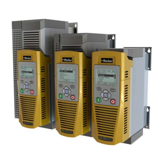
Parker AC30 Series Manual
Variable speed drive
Hide thumbs
Also See for AC30 Series:
- User manual (522 pages) ,
- Product manual (56 pages) ,
- Technical manual (46 pages)
Table of Contents
Troubleshooting

Related Manuals for Parker AC30 Series


Summary of Contents for Parker AC30 Series
- Page 1 AC30 series climate control electromechanical Variable Speed Drive filtration fluid & gas handling hydraulics pneumatics process control HA503711U003 Issue 2: Software Reference sealing & shielding ENGINEERING YOUR SUCCESS.
- Page 2 The user must analyze all aspects of the application, follow applicable industry standards, and follow the information concerning the product in the current product catalogue and in any other materials provided from Parker Hannifin Corporation or its subsidiaries or authorized distributors.
- Page 3 All rights strictly reserved. No part of this document may be stored in a retrieval system, or transmitted in any form or by any means to persons not employed by a Parker Hannifin Manufacturing Limited company without written permission from Parker Hannifin Manufacturing Ltd. Although every effort has been taken to ensure the accuracy of this document it may be necessary, without notice, to make amendments or correct omissions Parker Hannifin Manufacturing Limited cannot accept responsibility for damage, injury, or expenses resulting therefrom.
- Page 4 AC30 series Variable Speed Inverter...
-
Page 5: Table Of Contents
Set Up PMAC Motor Control – Pos Alignment after Power-up .. 6-12 The Display..................4-5 Top Line - Inverter Status Summary ............4-5 Parker Drive Quicktool (PDQ) PC Software ......... 6-13 Bottom Line – Soft Key Action Indication ..........4-6 Installation ....................6-13 Starting the Wizard .................. - Page 6 Explicit Access of Parameters ............... A-24 Troubleshooting the Web Server ............8-18 Lost Communications Trip ..............A-24 Simple Network Time Protocol (SNTP) Client ......8-19 Troubleshooting and Tips ..............A-25 SNTP Client Parameter Summary ............8-19 CIP Objects ....................A-26 AC30 series Variable Speed Inverter...
- Page 7 Control Mode ................... C-39 Pattern Generator ................. C-122 ControlNet Option ................... C-43 Peer to Peer ................... C-124 Current Limit .................... C-44 PID ......................C-125 Current Loop ..................C-45 PMAC Flycatching ................C-127 Current Sensor Trip ................C-46 AC30 series Variable Speed Inverter...
- Page 8 SB Encoder Slot 2 ................. C-182 AC30 Series Power Stack ................. D-2 SB Retransmit ..................C-183 Configured AC30 Series Inverter ............. D-3 AC30 Series Regenerative Supply Unit ........... D-4 Scale Setpoint ..................C-187 SD Card ....................C-188 Sequencing .................... C-189 Setup Wizard ..................
-
Page 9: Chapter 1: Safety
Cubicle mounted (refer to Component Relevant Apparatus Unit fitted: Through Panel Mounted Certification) Application Area The equipment described is intended for industrial motor speed control utilising AC induction motors or AC permanent magnet synchronous machines. AC30 series Variable Speed Inverter... -
Page 10: Personnel
Refer to "Routine (motor output, supply input phases, DC bus and the brake, where Maintenance and Repair". fitted) when the motor is at standstill or is stopped. AC30 series Variable Speed Inverter... - Page 11 Frame sizes E (11kW) to N harmonics conform to the limits of handling, installing and servicing this product. IEC61000-3-12:2011 (table 4). WARNING! – Control Unit Removal / Fitting Isolate supply before plugging or unplugging control unit to the power stack. AC30 series Variable Speed Inverter...
- Page 12 An inverter is a component within an inverter system that may influence its operation or effects under a fault condition. Consideration must be given to: • Stored energy • Supply disconnects • Sequencing logic • Unintended operation AC30 series Variable Speed Inverter...
-
Page 13: Chapter 2: Introduction
About this Manual Who is this Manual aimed at? This Manual is intended for use by the user and programmer of the AC30 series inverters. It assumes a reasonable level of understanding in these two disciplines. There are separate hardware installation references - HA503711U001 ‘AC30 Series Hardware Installation Manual: Frames D - J’ and HA503711U002 ‘AC30 Series Hardware Installation Manual: Frames K - N’... -
Page 14: Appendix C: Parameter Reference
• decide on the best menu level for the Graphical Keypad (GKP) where supplied. Programming: Use of the Parker Drive Quicktool or Parker Drive Developer (pc programming tools) Know your application: •... -
Page 15: Chapter 3: Product Overview
Product Overview Product Overview Chapter 3: Product Range Power Stacks – Frame Sizes D, E, F, G, H, J, K, L, M & N Control Modules – AC30V, AC30P, AC30D & AC30A AC30 series Variable Speed Inverter... -
Page 16: Power Stack Features
4kHz switching frequency it is 4000/8 = 500Hz Maximum is Switching Frequency divided by 6, in PMAC Motor Closed Loop Control. If >590Hz is required, please contact your local Parker Sales representative. Dual Rating Normal duty (ND) Heavy duty (HD) -
Page 17: Functional Overview
Product Overview Functional Overview Block Diagram for Frames D, E, F AC30 series Variable Speed Inverter... - Page 18 Product Overview Block Diagram for Frames G, H, J AC30 series Variable Speed Inverter...
- Page 19 Product Overview Block Diagram for Frame K AC30 series Variable Speed Inverter...
- Page 20 Product Overview Block Diagram for Frames L - N AC30 series Variable Speed Inverter...
-
Page 21: Ac30 Series Control Features
1 selectable encoder output supply voltage (AC30D & AC30A only) Encoder Outputs 1 encoder transmit channel: A, /A, B, /B, Z, /Z (AC30D & AC30A only) Comms On-board Ethernet 1 port (AC30V only) 2 ports AC30 series Variable Speed Inverter... - Page 22 Product Overview AC30 series Variable Speed Inverter...
-
Page 23: Chapter 4: The Graphical Keypad
It provides for local control of the inverter, monitoring, and complete access for application programming. Insert the Keypad into the front of the inverter (replacing the blank cover); or if supplied separately to be used remotely, up to 3 meters away, use the mounting kit with connection lead. AC30 series Variable Speed Inverter... -
Page 24: Overview
The central navigation and editing keys are referred to as UP, DOWN, LEFT, RIGHT and • The Run, (green), and Stop, (red), keys are used to start and stop the motor when the inverter is in local control mode. AC30 series Variable Speed Inverter... -
Page 25: Keypad
Moves ‘back’ to the previous menu list / Selects the digit of the parameter being LEFT edited. Moves ‘into’ the next menu list or parameter / Selects the digit of the parameter RIGHT being edited. AC30 series Variable Speed Inverter... -
Page 26: Led Status Indication
Inverter Status: Run Key Stop Key STOPPED RUNNING FLASHING STOPPING FLASHING AUTO RESTART PENDING NOT IN AN OPERATIONAL FLASHING (IN SYNC) STATE FLASHING (ALTERNATING) FAULT STATE Note: The LED operation can be over-ridden by the application. AC30 series Variable Speed Inverter... -
Page 27: The Display
-ve direction from control (solid) (solid) terminals Comms: IP Address Stopped Maintenance configured, PTP Start / Stop (ready to run in required clock from comms +ve direction) synchronised master Stopped (ready to run in -ve direction) AC30 series Variable Speed Inverter... -
Page 28: Bottom Line - Soft Key Action Indication
Add to ‘Favourites’ menu Displayed: while viewing parameter attributes. Soft key action: Adds parameter to the ‘Favourites’ menu. Remove from ‘Favourites’ menu Displayed: while viewing parameter attributes. Soft key action: Removes parameter from the ‘Favourites’ menu. AC30 series Variable Speed Inverter... -
Page 29: The Menu System
) is shown over Soft Key 1, pressing this key will abort the edit, leaving the value unchanged. To accept the edited value, press the center OK key. Refer to Chapter 5 for a description of the menu items AC30 series Variable Speed Inverter... -
Page 30: Trips And Other Information Displays
When changing language, there may will be a short delay while the updated text is transferred to the GKP. During this period the GKP will be unresponsive. An information message “UPDATING LANGUAGE” is displayed during this process. The GKP has the following language files built in as standard: English French German Spanish Italian AC30 series Variable Speed Inverter... -
Page 31: Setup Wizard
Wizard to be run again, though If this is required, this can be achieved as detailed above in ‘Starting the Setup Wizard’. Refer to chapter 6 for a more detailed explanation of the Setup Wizard AC30 series Variable Speed Inverter... -
Page 32: Firmware Update
Alternatively, the latest firmware can be copied through the Parker Drive Quicktool (PDQ), using the ‘Drive Maintenance’ task. Copy the firmware onto an SD card. The file must be named firmware.30x for the AC30V, or firmware.30p for the AC30P and AC30D. -
Page 33: Chapter 5: Menu Organisation
SB Encoder Slot1 Trips SB Encoder Slot2 Communications Regen Control Base Ethernet Favourites Base Modbus Parameters* Base Ethernet IP Option Peer to Peer * The “Parameters” menu is intended for expert use only, see Appendix D AC30 series Variable Speed Inverter... -
Page 34: Menu Descriptions
Press the soft key 2 to add to or Favourites menu. remove from Favourites Press and hold the OK key until the Attributes screen is OK Key shown, (hold for about 2s). Press the “Remove from Favourites” soft key, AC30 series Variable Speed Inverter... -
Page 35: Parameters
PMAC Rated Torque 0558 Regen Control PMAC Motor Poles 0559 Motor Type or AFE 0511 PMAC Back Emf Const KE 0560 AFE Inductance 1730 PMAC Base Volt 1387 AFE VDC Demand 1711 AFE Current Control 1693 AC30 series Variable Speed Inverter... - Page 36 System Board Option BACnet Baud Rate 1093 System Board Required 1739 BACnet MSTP Timeout 1094 Output Enable 1678 BACnet IP Device ID 0209 Output Source 1679 BACnet IP Timeout 0210 Output Voltage 1680 CANopen Node Address 0212 AC30 series Variable Speed Inverter...
- Page 37 Peer to Peer Enable 1725 Anin 13 Value 1183 Destination IP Address 1726 Encoder Speed 1516 Destination Port 1727 Encoder Count 1518 Local Port 1728 SB Digital Input 1 1759 Clone SB Digital Input 2 1722 AC30 series Variable Speed Inverter...
- Page 38 PROFINET State 0239 AFE Status 1721 PROFINET Device Name 0240 DC Link Voltage 0392 CANopen State 0211 Favourites ControlNet State 0214 DeviceNet State 0218 CANopen Actual Baud 1251 DeviceNet Actual Baud 0221 Comms Supervised 0047 AC30 series Variable Speed Inverter...
-
Page 39: Chapter 6: Setup Wizard
Information that you will need in order to set up the motor control When you run the setup wizard you will be asked for various items of information in order to set up the motor control. AC30 series Variable Speed Inverter... -
Page 40: Setup Wizard Stages
All parameters are saved on completion of the GKP wizard regardless of the setting of this parameter. Also, this parameter is always saved when changed. 0961 Drive Name Defaults to show the Ethernet MAC address AC30 series Variable Speed Inverter... -
Page 41: Application Selection
The maximum positive excursion, (limit), of the PID controller. ● 1933 PID Output Neg Limit The maximum negative excursion, (limit), of the PID controller. ● 1934 PID Output Scaling The overall scaling factor which is applied after the positive and negative limit clamps AC30 series Variable Speed Inverter... -
Page 42: Input And Output Option
Anin 02 Type Select the hardware range for analog input 2 0003 Anout 01 Type Select the hardware range for analog output 1 0004 Anout 02 Type Select the hardware range for analog output 2 AC30 series Variable Speed Inverter... -
Page 43: Motor Data
1809 PMAC Wiring ● 0565 PMAC Therm Time Const The motor’s thermal time constant ● 0564 PMAC Motor Inertia The motor’s inertia ● 0478 PMAC SVC Start Cur The current level during the startup procedure. AC30 series Variable Speed Inverter... -
Page 44: Fieldbus Options
CANopen Node Address ● 0213 CANopen Baud Rate ● 0048 Comms Trip Enable These parameters are shown when the DeviceNet option is fitted. Parameter Comment 0044 Comms Required DEVICENET Refer to DeviceNet Technical Manual HA501840U001 AC30 series Variable Speed Inverter... - Page 45 Refer to Profinet IO Technical Manual HA501838U001 ● 0199 Address Assignment ● 0200 Fixed IP Address ● 0201 Fixed Subnet Mask ● 0202 Fixed Gateway Address ● 0203 Option Web Enable ● 0048 Comms Trip Enable AC30 series Variable Speed Inverter...
-
Page 46: Autotune Parameters
Once the Setup Wizard has been run to completion the feature is automatically disabled. Re-starting the inverter will not cause the Setup Wizard to be run again. (If it is desired to re-run the Setup Wizard, this can be achieved as detailed above in “Starting the Setup Wizard”). AC30 series Variable Speed Inverter... -
Page 47: Set Up Pmac Motor Control - Sensorless
0564 PMAC Motor Inertia Reduce speed loop bandwidth /Motor Control / Spd Loop Settings 1247 Ratio Load Mot Inertia 01248 Speed Loop Bandwidth Motion too smooth ? Increase speed loop bandwidth End of minimum settings AC30 series Variable Speed Inverter... -
Page 48: Set Up Pmac Motor Control - Encoder Feedback
Encoder Slot 1? 1664 Encoder Lines 1665 Encoder Invert 1666 Encoder Type /Inputs and Outputs/SB Encoder Slot2 /System Board/Encoder Slot 2 1761 Encoder Supply Encoder Slot 1? 1671 Encoder Lines 1672 Encoder Invert 1673 Encoder Type AC30 series Variable Speed Inverter... - Page 49 0564 PMAC Motor Inertia Reduce speed loop bandwidth /Motor Control / Spd Loop Settings 1247 Ratio Load Mot Inertia 01248 Speed Loop Bandwidth Motion too smooth ? Increase speed loop bandwidth End of minimum settings AC30 series Variable Speed Inverter...
-
Page 50: Set Up Pmac Motor Control - Pos Alignment After Power-Up
The first start command will run the Pos Alignment sequence. A running and successfully sequence resets Alignment_Enable to FALSE. A 1s negative pulse is generated at the end of the sequence. This information can be used to toggle any command to start the system. AC30 series Variable Speed Inverter... -
Page 51: Parker Drive Quicktool (Pdq) Pc Software
6-13 Setup Wizard Parker Drive Quicktool (PDQ) PC Software Installation Launch the installer, setup.exe, from the latest version from www.parker.com/ssd/pdq AC30 series Variable Speed Inverter... - Page 52 6-14 Setup Wizard Figure 9-1 InstallShield Follow the steps of the InstallShield Wizard. AC30 series Variable Speed Inverter...
-
Page 53: Starting The Wizard
Setup Wizard Starting the Wizard Figure 9-2 Desktop shortcut Once the InstallShield completes, run the PDQ from the “Start” menu as shown or from the desktop shortcut as shown in Figure 9-3 Start the Wizard AC30 series Variable Speed Inverter... -
Page 54: Task Selection
Note: For Wizard tasks no data or settings will be changed in the Drive until the “Commission” page is reached and download is confirmed by the Engineer. For offline projects a Login button is provided to go online to a connected Drive and make changes. AC30 series Variable Speed Inverter... - Page 55 Information about the selected Drive will be displayed in the status area at the bottom of the screen. Ensure you have selected the correct Drive before continuing. If Drive Brake Switch is not fitted it will be indicted by the symbol as shown in Figure 9-5. AC30 series Variable Speed Inverter...
- Page 56 Connect Drive and PC to the same network or directly to network as the PC each other Drive found but no Another person has their PC connected to the Drive Disconnect the other PC information displayed AC30 series Variable Speed Inverter...
-
Page 57: Application Macro
Figure 9-6 Macro selection Select the desired Application Macro from the drop down list. Adjust any parameters that are needed for your specific application. To make changes to the application logic choose the Custom button. AC30 series Variable Speed Inverter... -
Page 58: Drive Hardware
6-20 Setup Wizard Drive Hardware On the Drive Hardware page there are 4 tabs for Motor setup, Motor Control Strategy, IO setup and Communication setup. AC30 series Variable Speed Inverter... -
Page 59: Motor Setup
The Motor Setup tab allows the engineer to define the motor parameters or use the built in motor database to search and select known motor data. Other parameters such as acceleration and deceleration can also be entered here. AC30 series Variable Speed Inverter... -
Page 60: Motor Control Strategy
The “Motor Control Strategy” tab allows configuration of the Drive control. The figure above shows a simple V/Hz control strategy but when Vector Control is selected additional parameters are shown for the user to select and configure. AC30 series Variable Speed Inverter... -
Page 61: I/O
6-23 Setup Wizard On this tab the I/O can be changed. If an I/O option card is fitted it can be configured in the “I/O Option” drop down. AC30 series Variable Speed Inverter... -
Page 62: Communications
Figure 9-9 Drive Communications setup If required, the built in Modbus can be setup from, the “Base Modbus Communication” selection. If an optional Fieldbus is fitted, it can be configured from the “Comms Option” selection. AC30 series Variable Speed Inverter... - Page 63 1. Enter the Project File name and the Drive’s name in the left of the screen. “Program Drive”. This step writes your settings to the Drive and overwrites any existing configuration in the Drive. After these steps, the Drive is ready to use. AC30 series Variable Speed Inverter...
-
Page 64: Monitor The Drive
6-26 Setup Wizard Monitor the Drive Figure 9-11 Monitor the Drive and fine tune AC30 series Variable Speed Inverter... - Page 65 6-27 Setup Wizard Figure 9-16 Scoping Drive Parameters AC30 series Variable Speed Inverter...
- Page 66 6-28 Setup Wizard AC30 series Variable Speed Inverter...
-
Page 67: Chapter 7: Trips & Fault Finding
2. In remote terminal sequencing mode, create a 0 to 1 transition on the RESET TRIP bit, (bit 7), in the App Control Word parameter. 3. In remote communications sequencing mode, create a 0 to 1 transition on the RESET TRIP bit, (bit 7), in the Comms Control Word parameter. AC30 series Variable Speed Inverter... -
Page 68: Using The Keypad To Manage Trips
V/Hz mode only: If the current exceeds 200% of stack rated current for a period Not applicable. CURRENT LIMIT of 1 second, the drive will trip. This is caused by shock loads AC30 series Variable Speed Inverter... - Page 69 Refer to the application description to identify the source of the signal • External dynamic brake resistor has been overloaded: Not applicable. BRAKE SHORT The external dynamic brake has developed a short circuit. • Wiring fault • AC30 series Variable Speed Inverter...
- Page 70 5 seconds to move from open to ERROR closed loop control or to move from closed to open loop Overspeed: Not applicable. OVERSPEED >150% base speed when in Sensorless Vector mode • AC30 series Variable Speed Inverter...
- Page 71 IO option has not been declared as required. An internal cooling fan has failed. This will reduce the lifetime of the power electronics. Not applicable. INTERNAL FAN Return the power stack to a Parker Hannifin repair centre. FAIL • Current feedback phase missing Not applicable.
- Page 72 CONFIGURATION match the configuration. Check PNO1178 Option IO Required, PNO0044 Comms Required and PNO0987 • Power Stack Required. Half the trip time The application is taking longer than 500ms to complete a single execution. APPLICATION AC30 series Variable Speed Inverter...
- Page 73 Combination of high switching frequency, high network traffic and complicated CPU USAGE least 0.5s before the trip. configuration. Run the application at a slower task rate, reduce the Ethernet load or reduce the switching frequency. AC30 series Variable Speed Inverter...
-
Page 74: Hexadecimal Representation Of Trips
00020000* VDC RIPPLE 00200000 CPU Usage 00040000* BASE MODBUS BREAK 00400000 * These masks apply to parameter words “33 – 64” 24V OVERLOAD 00800000 PMAC SPEED ERROR 01000000 OVERSPEED 02000000 AC30 series Variable Speed Inverter... -
Page 75: Runtime Alerts
A Runtime Alert is a fault that indicates a permanent hardware error. The Runtime Alert display is of the form RUNTIME ALERT CODE 00000000 CODE is a number in the range 0 to 65000. The following value is used to provide additional information to assist Parker Hannifin Technical Support personnel. CODE ERROR... - Page 76 Option reset problem. Upgrade drive firmware to 1.11 or greater to improve the option reset control. • 1601 Stack internal fault Return the power stack to Parker Hannifin repair center. • 1602 Incompatible stack Return the power stack to Parker Hannifin repair center.
-
Page 77: Autotune Alerts
Check the motor data is correct, especially nameplate rpm, too small (the min value is 1V) rated amps and motor volts. ALL TESTS DISABLED All auto tune tests are disabled Check parameter 0257: Autotune Test Disable AC30 series Variable Speed Inverter... -
Page 78: Other Alerts
It may be necessary to repeat the auto tune with the higher value of max speed. The stack is not known to the firmware Upgrade the drive firmware. ** ALERT ** UNKNOWN STACK AC30 series Variable Speed Inverter... - Page 79 Unreliable connection to the system board Power off / on then verify that the system board is functioning ** ALERT ** correctly. SYSTEM BOARD If this message occurs more than once contact the service CHANGED department for assistance. AC30 series Variable Speed Inverter...
-
Page 80: Fault Finding
STO fault. Motor runs and stops Motor becomes jammed Stop the drive and clear the jam Open circuit speed reference Check terminal potentiometer AC30 series Variable Speed Inverter... -
Page 81: Black Box Feature
Motor sequencer state • Motor sequencer start and stop states. • Main sequencer state, (parameter 0678 Sequencing State) • High current limit activity • Stall trip torque limit state • Stall trip current limit state AC30 series Variable Speed Inverter... - Page 82 The motor control type, (parameter 0511 Motor Type or AFE) • The control strategy, (parameter 0512 Control Stragegy) • The control type, (parameter 1533 Control Type) • The firmware version • The version of CoDeSys used to create the application. AC30 series Variable Speed Inverter...
-
Page 83: Diagnostic Leds
1s when the drive firmware is active and 2s in the Firmware Update mode HEALTH LED RUN LED STOPPED RUNNING STOPPING, (NORMAL) QUICKSTOPPING FAULTED INITIALISING CONFIGURATION MODE CONFIGURATION FAULT FIRMWARE UPDATE – Idle FIRMWARE UPDATE - Erasing firmware FIRMWARE UPDATE – Writing firmware AC30 series Variable Speed Inverter... - Page 84 7-18 Trips & Fault Finding AC30 series Variable Speed Inverter...
-
Page 85: Chapter 8: Ethernet
Insert the Ethernet cable as shown below on an AC30V. Connection is recommended via an Ethernet switch. To remove the cable first remove the GKP and then insert a screwdriver to release the catch on the Ethernet clip. Ethernet LEDs Activity Link AC30 series Variable Speed Inverters... -
Page 86: Ac30P Or Ac30D
Port 2 LEDs Port 1 LEDs Activity Activity Link Link DO NOT TOUCH DO NOT touch the board surface via the aperture shown Insert the Ethernet cable on an AC30P or AC30D as shown below. AC30 series Variable Speed Inverters... -
Page 87: Ethernet Setup
The parameters 0929 DHCP and 0930 Auto IP are used to determine how the IP address is set. The default of these two parameters is TRUE. The parameter 0936 Setting Lock, when set to TRUE, prevents a configuration tool from modifying the IP settings. AC30 series Variable Speed Inverters... - Page 88 The Inverter will store this IP address (in parameter 0931 Last Auto IP Address) and attempt to use it next time Auto-IP is used. The gateway address is fixed to 0.0.0.0 AC30 series Variable Speed Inverters...
- Page 89 The inverter will take a link-local address in the range 169.254.*.* if no DHCP server is discovered on the network. If a DHCP server is available (or becomes subsequently available) then the inverter will take the IP address from the server. Note that the DHCP has precedence. AC30 series Variable Speed Inverters...
-
Page 90: Typical Wiring Configurations
PC’s network settings (see the section Troubleshooting the Ethernet – Changing the Ethernet settings on the PC). Note: It may take some PCs up to 2 minutes to obtain an Automatic private IP address when the Ethernet cable is plugged in. AC30 series Variable Speed Inverters... - Page 91 Port 2 on the left-hand side inverter to Port 1 on the right-hand side inverter. However, an Ethernet loop MUST be avoided. AC30 series Variable Speed Inverters...
-
Page 92: Ethernet Parameter Summary
- IP address is set – communication is possible 6: STOPPING DHCP - Inverter is stopping the DHCP service 7: DUPLICATE IP - Another device on the network has the same IP address 8: FAULT - Fault detected AC30 series Variable Speed Inverters... - Page 93 255.255.255.255 Comms:: Ethernet Ethernet parameter. Provides the current gateway address of the Ethernet. 0931 Parameters::Base Comms:: 0.0.0.0 0.0.0.0 to NEVER Last Auto IP Address Ethernet 255.255.255.255 Ethernet parameter. Provides the last Auto-IP IP address used. AC30 series Variable Speed Inverters...
- Page 94 0 to NEVER Free Packets Ethernet Ethernet parameter. Diagnostic providing the remaining number of Ethernet packets 1782 Parameters::Base Comms:: 0 to NEVER Free Sockets Ethernet Ethernet parameter. Diagnostic providing the remaining number of BSD sockets. AC30 series Variable Speed Inverters...
- Page 95 0.0.0.0 to ALWAYS User Gateway Address Ethernet Parameters::Base 255.255.255.255 Comms:: Ethernet Ethernet parameter. The preferred fixed gateway address of the Ethernet. For the Ethernet to take on this address both DHCP and Auto-IP must be disabled. AC30 series Variable Speed Inverters...
-
Page 96: Troubleshooting The Ethernet
1 minute once the conflicting device has been removed or the IP address changed. Fault An Ethernet loop has been detected. To clear the fault, break the loop by removing an Ethernet cable from one of the ports. AC30 series Variable Speed Inverters... - Page 97 When first connected, the inverter will attempt to determine the speed and duplex of the Ethernet link. This is done using a method call auto- negotiation. Some older devices or hubs do not support auto-negotiation, in which case the inverter will use parallel detection. As parallel detection will only provide the link speed, the inverter will default to half-duplex. AC30 series Variable Speed Inverters...
- Page 98 To use a fixed IP address make sure Use the following Ip address under the General tab is chosen and enter the required IP address, subnet mask and default gateway. To use DHCP or Auto-IP make sure Obtain IP address automatically under the General tab is selected and under the Alternate Configuration tab that Automatic private IP address is selected. AC30 series Variable Speed Inverters...
-
Page 99: Web (Http) Server
If the pop-up box is cancelled then a read-only Parameters page will be shown. The read-only web page allows parameters to be viewed but not changed. AC30 series Variable Speed Inverters... - Page 100 Note 2. The username and password are case sensitive. Note 3. If passwords are lost, they may only be cleared by a return to defaults of all the parameters. AC30 series Variable Speed Inverters...
-
Page 101: Web Server Parameter Summary
0946 Parameters::Base none ALWAYS Web Password Comms::Web Server Web Server parameter. Sets the password for access to restricted inverter web pages such as the Parameters Page. This may only be changed on the web Services page. AC30 series Variable Speed Inverters... -
Page 102: Troubleshooting The Web Server
LAN settings. Make sure the Proxy server checkbox is cleared, alternatively click on Advanced and add the IP address of the inverter to the Exceptions list. Contact your network administrator before making any changes to your browser settings. AC30 series Variable Speed Inverters... -
Page 103: Simple Network Time Protocol (Sntp) Client
The smaller the error, the longer the request period. If an option if fitted that includes a Real Time Clock, the RTC is also updated by the SNTP Client if the RTC and SNTP time are more than 1s apart. AC30 series Variable Speed Inverters... -
Page 104: Sntp Relationship With Time Zone And Daylight Saving
Offset, and PNO1225 DST Active. Set the Time Zone Offset to control the difference in hours between the local time zone and UTC. If Daylight Saving Time is active, set DST Active to add one hour to the displayed time. AC30 series Variable Speed Inverters... -
Page 105: Simple Network Time Protocol (Sntp) Server
The local RTC hardware only tracks time to the nearest second. This limits the precision of the AC30 SNTP server. The SNTP server transmits UTC time, see above for a description of the relationship between UTC time, the local time zone and daylight saving. AC30 series Variable Speed Inverters... -
Page 106: Precision Time Protocol (Ptp)
Standard Ethernet switches may be used with the E2E mode but is not recommended as it can add an indeterminate delay between clocks. Address and ports The PTP protocol uses the multicast IP address 224.0.1.129 and UDP ports 319 (event) and 320 (general). AC30 series Variable Speed Inverters... - Page 107 Delay_Req message traffic. announceReceiptTimeout The value of announceReceiptTimeout will specify the number of announceInterval that has to pass without receipt of an Announce message AC30 series Variable Speed Inverters...
- Page 108 First 3 octets – most significant octets of MAC address Next 2 octets – have values FFh and FEh respectively Last 3 octets – least significant octets of MAC address The clockIdentity is used as a tie-breaker for the master clock. AC30 series Variable Speed Inverters...
-
Page 109: Ptp Parameter Summary
Comms::PTP PTP parameter. Sets the PTP clock mode to either end-to-end (E2E) or peer-to-peer (P2P). See description in section Advanced Users for more details. Note that currently E2E is only available. Enumerated values: 0: E2E AC30 series Variable Speed Inverters... - Page 110 Lock Threshold then the slave clock is deemed to be synchronised as indicated by the parameter 1688 PTP Locked. Note that it will take longer for a slave clock to be deemed synchronised when a smaller threshold is set. AC30 series Variable Speed Inverters...
- Page 111 8-27 Ethernet Parameter Name Path Default Range Units Writable Monitor::Communications::P NONE 0:NONE NEVER PTP State TP Parameters::Base 1:INITIALISNG Comms::PTP 2:FAULTY 3:DISABLED 4:LISTENING 5:PRE-MASTER 6:MASTER 7:PASSIVE 8:UNCALIBRATE 9:SLAVE AC30 series Variable Speed Inverters...
- Page 112 NEVER PTP Clock TP Parameters::Base 00:00:00 Comms::PTP PTP parameter. Diagnostic parameter giving the current value of the PTP clock to 1 second accuracy. Note this is not intended to represent the actual date and time. AC30 series Variable Speed Inverters...
- Page 113 Diagnostic parameter indicating when the inverter is a slave that the PTP clock has synchronised to a master clock determined by parameter 1685 PTP Locked Threshold. If the inverter is a master then this parameter will be set to TRUE. AC30 series Variable Speed Inverters...
-
Page 114: Peer To Peer
To enable the Peer to Peer module set the parameter 1725 Peer to Peer Enable to TRUE on all inverters participating. For most applications the default settings may be used. For further configuration of the module see the section Peer to Peer Parameter Summary. AC30 series Variable Speed Inverters... - Page 115 Sets the UDP port number the Peer to Peer module sends data to. Normally this will be set the same as the Local Port. Setup::Communications::Peer 1250 1 to ALWAYS Local Port to Peer Parameters::Base 65535 Comms::Peer to Peer Peer to Peer Parameter. AC30 series Variable Speed Inverters...
- Page 116 - the Peer to Peer module is disabled. 1: ACTIVE - the Peer to Peer module is enabled and ready for communications. 2: ERROR - the Peer to Peer module is in an error state and communications could not be established. AC30 series Variable Speed Inverters...
-
Page 117: Chapter 2: Fire Mode
When Fire Mode is deactivated the drive will return to its previous sequencing mode. If the drive was running in Local mode the motor will be stopped. If the drive was running in remote terminals or remote communications mode the drive will continue running according to the relevant control word, (refer to Appendix B). AC30 series Variable Speed Drive... -
Page 118: Configuration
The activation count will be reset if an application is loaded that does not implement Fire Mode. ∗ These PNO values are correct for the Fan Application. Custom configurations may assign the Fire Mode parameter to different PNOs. AC30 series Variable Speed Drive... -
Page 119: Functional Description
The Fire Mode Setpoint parameter is selected automatically whenever Fire Mode is Activated. The Setpoint is passed through the System Ramp, (see Appendix D). Caution Fire Mode does not override the standard Ramp features. Specifically 0497 Ramp Hold can prevent the setpoint changing to the Fire Mode Setpoint value. AC30 series Variable Speed Drive... -
Page 120: Trips And Auto Restart
BRAKE SWITCH LOCAL CONTROL COMMS BREAK LINE CONTACTOR PHASE FAIL VDC RIPPLE BASE MODBUS BREAK 24V OVERLOAD PMAC SPEED ERROR AC30 series Variable Speed Drive... - Page 121 The Fly catching feature can be used to allow the drive to smoothly resume control of a moving load on restart. The operation of Fire Mode is independent of the motor type motor and the control mode, (Open Loop or Sensorless Vector control). AC30 series Variable Speed Drive...
- Page 122 Fire Mode AC30 series Variable Speed Drive...
-
Page 123: Chapter A: Fieldbuses
User-defined mapping to the inverter parameter values. 00257 - 00528 00257 - 00528 Reserved area. Do not write into this register range. 00529 - onwards 00529 - onwards Fixed mapping to the inverter parameter values. AC30 series Variable Speed Inverter... -
Page 124: Fixed Parameter Mapping
Accessing the parameter arrays via the parameter number that represents the whole array is not recommended. This will access only the first four bytes (2 registers) of the array. The array should rather be accessed via its elements. AC30 series Variable Speed Inverter... - Page 125 To access the whole string over Modbus use the registers that map to the parameter number of the whole array plus one, in this example 0162 (register 00851). A multiple read or write of registers will then provide access to the whole string. AC30 series Variable Speed Inverter...
- Page 126 Note: This example is not a real parameter. To access the first element of the array over Modbus then parameter number 0177 (register 00881) would be used. To access the second element then parameter number 0180 (register 00887) would be used. AC30 series Variable Speed Inverter...
-
Page 127: User-Defined Parameter Mapping
If the diagnostic parameter is FALSE, meaning there are invalid entries, then Modbus requests are still accepted but the invalid entries will be skipped over and will occupy no registers in the mapping. AC30 series Variable Speed Inverter... -
Page 128: Password Protection
A read of Modbus register 00518 will always respond with a value of 0000 regardless of the password being locked or unlocked. • Locking and unlocking the password will apply to all Modbus connections. • When all Modbus connections are closed, write access will returned back to the locked state if a password is set. AC30 series Variable Speed Inverter... -
Page 129: Supported Modbus Functions
This function allows a contiguous block of Holding registers to be written to. Up to 120 registers may be written. Note that when writing to registers that map to 4-byte inverter parameters both registers must be written to. Writing to one-half of a 4-byte parameter will have no effect on the parameter. AC30 series Variable Speed Inverter... -
Page 130: Modbus Exception Codes
This is useful, for example, if the link between the server and client is lost, otherwise the connection may remain open indefinitely. AC30 series Variable Speed Inverter... -
Page 131: Parameter Summary
Indicates that a Modbus request addressed to this node has been received within the period set by the parameter Modbus Timeout, or if no timeout is specified, this parameter will stay active after the first received Modbus request. AC30 series Variable Speed Inverter... - Page 132 Modbus password. When set to a value other than zero, write access to parameters via the fixed mapping registers will be restricted. To unlock the password, write to the Modbus register 00518 the value set in this password. A subsequent write of value 0000 to Modbus register 00518 will lock the password. AC30 series Variable Speed Inverter...
-
Page 133: Ethernet/Ip Adapter
To make use of this feature, firmware version V3.x.x needs to be installed in the inverter. The firmware may be updated by downloading the firmware file from the Parker website (see section Firmware Update in Chapter 4) or installed from the latest version of PDQ. With version V3.x.x firmware installed, the AC30EIPS CoDeSys (PDQ/PDD) device is required. -
Page 134: Inverter Configuration
If both parameters 0929 DHCP and 0930 Auto IP are FALSE, then the IP address, subnet mask and gateway address will be set from the values in the parameters: 0933 User IP Address 0934 User Subnet Mask 0935 User Gateway Address AC30 series Variable Speed Inverter... - Page 135 The default input mapping is 0000 given in the table. If the input and output mappings have invalid entries then the parameter 3130 EtherNet IP State will report ERROR and the inverter will not go into the Operational state. AC30 series Variable Speed Inverter...
- Page 136 Enter the inverter IP address into the web browser and access the web page “Services” and under EtherNet/IP EDS file click the Download button. Alternatively type the following into the browser address bar (replacing ip_address with the inverter’s IP address): ip_address/eds/eips.zip AC30 series Variable Speed Inverter...
-
Page 137: Example Plc Configurations
0627 Comms Control Word WORD 0395 Actual Speed Percent REAL 0681 Comms Reference REAL 0000 0000 A CompactLogic L32E controller is used. 1. Start a new project from within RSLogix 5000 and select the required controller. AC30 series Variable Speed Inverter... - Page 138 A-16 Fieldbuses Open the Ethernet Port properties and enter the IP address of the Controller. 3. Right-click on the Ethernet Port and select New Module. Under Communications select the Generic Ethernet Module. AC30 series Variable Speed Inverter...
- Page 139 6 bytes. The Output Assembly Instance is 150 and in this example the data size is a total of 6 bytes. The mapping sizes on the inverter MUST match that on the PLC. Set the Configuration Assembly Instance to 128 size 0. 5. Within the Controller Tags the communications data arrays are automatically created: AC30 series Variable Speed Inverter...
- Page 140 7. The data can be transferred between the communication data arrays and the program data using the Synchronous Copy File (CPS) copy instruction as shown in the ladder diagram. Note that the CPS function is not interrupted until the copy is done. AC30 series Variable Speed Inverter...
- Page 141 1. Start a new project from CoDeSys using a CODESYS Control Win V3 device. 2. From the CoDeSys menu select Tools->Device Repository… and install the AC30 EDS file. The device will appear under Fieldbuses as shown. AC30 series Variable Speed Inverter...
- Page 142 3. Under Devices, select the CODESYS Control Win 3 device, right click and select Add Device…, then add an Ethernet Adapter. Under the Ethernet device add an EtherNet/IP Scanner. Under the EtherNet/IP Scanner add a Parker AC30 Drive. 4. Double-click on CODESYS Control Win 3 and under Communications Settings tab select Scan Network... and select the required PC (note the softPLC on the PC must be started).
- Page 143 A-21 Fieldbuses 5. Double-click on Ethernet and under the General tab select the required interface. 6. Double-click on Parker AC30 Drive and under the General tab set the IP address to that of the inverter. AC30 series Variable Speed Inverter...
- Page 144 7. Under the Connections tab edit the connection if necessary. The input mapping uses a total of 6 bytes (O->T) and the output mapping also uses a total of 6 bytes (T->O). The mapping sizes on the inverter MUST match that on the PLC. The RPI (Requested Packet Interval) may also be changed. AC30 series Variable Speed Inverter...
- Page 145 %QB0 will be the first byte of the Comms Control Word and %QB2 will be the first byte of the Comms Reference 9. In the application program the IO mappings can be accessed as variables as shown in this example. AC30 series Variable Speed Inverter...
-
Page 146: Explicit Access Of Parameters
A trip may be issued by the inverter on the loss of all Class1 connections of the EtherNet/IP adapter. To enable this, set the parameter 3129 EtherNet IP Trip to LOSS OF CONNECTION and set the ETHERNET IP BREAK bit in the parameter 0730 ENABLE 33 – 64. AC30 series Variable Speed Inverter... -
Page 147: Troubleshooting And Tips
• the Requested Packet Interval (RPI) of the scanner is set to less than 2ms Requested Packet Interval (RPI) When mapping a large amount of data use an RPI of at least 10ms. AC30 series Variable Speed Inverter... -
Page 148: Cip Objects
Product Name SHORT STRING “Parker AC30 Drive” Supported Service Code Service Name Get_Attribute_All Reset - Type 0 and Type 1 Reset are supported Get_Attribute_Single Both Type 0 and Type 1 Reset will restart DHCP if enabled. AC30 series Variable Speed Inverter... - Page 149 Attribute Description Type Value Access Input USINT[500] Parameter mapped values Output USINT[496] Parameter mapped values Get/Set Supported Service Code Service Name Get_Attribute_Single Set_Attribute_Single Connection manager – 06h There are no attributes for the Connection Manager. AC30 series Variable Speed Inverter...
- Page 150 Host Name derived from the AC30 MAC address. Encap TMO UINT Inactivity TMO seconds. Get/Set On Type 1 Reset this value will revert to a value of 120. Supported Service Code Service Name Get_Attribute_All Get_Attribute_Single Set_Attribute_Single AC30 series Variable Speed Inverter...
- Page 151 For a standard parameter the number of elements will be 1, for a parameter array it will be the number elements in the array, and for a string parameter it will be the maximum number of characters. AC30 series Variable Speed Inverter...
-
Page 152: Parameter Summary
Class 1 connection 3: CONNECTION IDLE Class 1 connection made with scanner in Idle mode 4: CONNECTION ACTIVE Class 1 connection made with scanner in Run mode 5: ERROR configuration error 8: NONE EtherNet/IP adapter disabled AC30 series Variable Speed Inverter... - Page 153 List of PNOs for the built-in fieldbus input parameter mapping. Output Mapping 3064 Setup::Communications::Base EtherNet 0661 0000 NEVER IP Parameters::Base Comms::Fieldbus 0395 Maximum parameter Mapping number 0000 … EtherNet/IP adapter parameter. List of PNOs for the built-in fieldbus output parameter mapping. AC30 series Variable Speed Inverter...
-
Page 154: Profinet Io Device
To make use of this feature, firmware version V4.x.x needs to be installed in the inverter. The firmware may be updated by downloading the firmware file from the Parker website (see section Firmware Update in Chapter 4) or installed from the latest version of PDQ. With version V4.x.x firmware installed, the AC30PNIO CoDeSys (PDQ/PDD) device is required. -
Page 155: Inverter Configuration
Minimum I/O Update Time Switching Frequency 2-4kHz 4-6kHz 6-8kHz 8-10kHz Induction motor control 16ms 32ms PMAC motor control 16ms 32ms Not permitted It is recommended to increase the update time for larger mapped cyclic I/O data. AC30 series Variable Speed Inverter... - Page 156 If it is preferred that this does not happen then the parameter 3134 PROFINET Use Drive IP should be set to TRUE. In this case, on enabling the PROFINET device the last IP address of the inverter will be used. AC30 series Variable Speed Inverter...
- Page 157 The AC30 default output mapping is given in the table alongside the equivalent mapping required in the PLC. AC30 Output Mapping Table PLC Inputs AC30 Parameter Data Type Plugged Modules 0661 Status Word WORD Input Unsigned16 0395 Actual Speed Percent REAL Input Real 0000 AC30 series Variable Speed Inverter...
- Page 158 Altenatively type the following into the browser address bar (replacing ip_address with the inverter’s IP address): ip_address/eds/pnio.zip The GSD file has the default mapping modules are ready plugged. This may be modified within the PLC configuration tool as required. AC30 series Variable Speed Inverter...
-
Page 159: Example Plc Configurations
Example Using a SIMATIC S7-300 PLC and SIMATIC Manager 1. Create a project Start SIMATIC Manager and create a new project. Right-click on the project name at the top level and from Insert New Object select SIMATIC 300 Station. AC30 series Variable Speed Inverter... - Page 160 Object. From the pop-up menu choose SIMATIC 300 RACK 300 Rail. The rail should then appear as shown. Right-click on slot 1 to add the appropriate power supply. Right-click on slot 2 to add the appropriate CPU. AC30 series Variable Speed Inverter...
- Page 161 5. Install the GSD file. Install the PROFINET IO GSD XML file. This can be downloaded from http://www.parker.com or from the inverter’s web server. From the Options menu select Install GSD File… This will then become available in the catalogue shown on the right-hand side of the window under PROFIBUS IO Additional Field Devices Drives...
- Page 162 Click on Properties… to set up the IP address and Subnet mask. Click on New… to create a new network and select this. Right-click on the PROFINET IO (PN-IO) Controller module and select Insert PROFINET IO System. AC30 series Variable Speed Inverter...
- Page 163 Set the Device Name (Station Name) of the slave. If the IP address of the slave is to be set by the PLC via DCP, check the Assign IP address via IO controller and click on Ethernet… to configure. AC30 series Variable Speed Inverter...
- Page 164 The slave will then take on its device name. This can be seen on the inverter parameter 3143 PROFINET Station Name. To help identify the slave click on Flashing on. The AC30 GKP will flash. AC30 series Variable Speed Inverter...
- Page 165 Update Time tab. The update time of the AC30 may be changed. 11. Save, compile and download. Make sure the PC/PLC interface is connected. Select Station from the menu and Save and Compile then select PLC and Download… AC30 series Variable Speed Inverter...
- Page 166 2. From the CoDeSys menu select Tools->Device Repository… and install the AC30 GSD file. The device will appear under Fieldbuses as shown. Two device access points (DAPs) are given: AC30 and AC30 DAP V2.2 Normally AC30 DAP would be used. AC30 series Variable Speed Inverter...
- Page 167 4. Under the PN-Controller right-click add the AC30 device. The default output and input modules will be added. These may be changed as required. Double-click on the AC30 device to modify the station name, IP address and update rate as required. AC30 series Variable Speed Inverter...
- Page 168 6. The Output and Input modules may be mapped to application variables in the PLC program. Double click on the required module and select the PNIO Module I/O Mapping tab. Under Variable click on the ellipses to select the required application variable. AC30 series Variable Speed Inverter...
- Page 169 Scan for Devices… The Station Name of the required device can be modified. Select Set Name+IP for this to take effect. Note that the device may also be added from this dialog box rather than adding it manually. 8. Build the project and go online. AC30 series Variable Speed Inverter...
-
Page 170: Acyclic Access Of Inverter Parameters
New data received and is valid RDREC only DONE Data written WRREC only BUSY Function block is busy ERROR Error detected See Record Error Codes section STATUS Last detected status See Record Error Codes section AC30 series Variable Speed Inverter... - Page 171 PNIO Read/Write Code 1 0x80 Invalid Index 0x81 Write Length Error 0x82 Invalid Slot or Subslot 0x84 Invalid Area API 0x86 Access Denied 0x87 Invalid Range 0x8B User Specific (record length not big enough) Code 2 AC30 series Variable Speed Inverter...
- Page 172 A CoDeSys (V3.5 SP11) soft PLC running on a PC is used. In this example, two parameters are accessed: • Reading from parameter 0005 Digin Value of data type WORD • Writing to parameter 0305 Current Limit of data type REAL Example structured text code to access these parameters acyclically is shown below. AC30 series Variable Speed Inverter...
-
Page 173: Lost Communications Trip
PROFINET is enabled. The IP address is subsequently set when the PLC next makes a connection. This behavior is part of the PROFINET standard. However, this may be overridden by setting the parameter 3134 PROFINET Use Drive IP to TRUE so that the last IP address used will be set at startup. See DCP Assignment section. AC30 series Variable Speed Inverter... -
Page 174: Parameter Summary
The most significant byte (MSB) of the data is sent first. PROFINET Station 3136 Monitor::Communications::Base PROFINET NEVER Name Parameters::Base Comms::PROFINET IO Device PROFINET IO parameter. Indicates the PROFINET device Station Name. Only the first 21 characters are displayed. AC30 series Variable Speed Inverter... - Page 175 Inverter has rejected a connection attempt from the PLC due to invalid switching frequency and update time combination. 4: MAPPING MISMATCH The mapping between the PLC and inverter does not match. A connection may still be allowed in this state. AC30 series Variable Speed Inverter...
- Page 176 3064 Setup::Communications::Base PROFINET 0661 0000 NEVER Parameters::Base Comms::Fieldbus Mapping 0395 Maximum parameter number 0000 … PROFINET IO parameter. List of PNOs for the built-in fieldbus output parameter mapping. These map to the PLC input modules. AC30 series Variable Speed Inverter...
-
Page 177: Chapter 2: Sequencing Logic
OPERATIONAL ENABLED - Voltage applied to the motor terminals. QUICKSTOP ACTIVE Emergency stop (Fast stop) is active FAULT REACTION ACTIVE The Drive is processing a trip event FAULTED The Drive is tripped awaiting trip reset AC30 series Variable Speed Inverter... -
Page 178: Sequencing Diagram
Sequencing Logic Sequencing Diagram No Power NOT READY TO SWITCH ON From all states SWITCH ON DISABLED FAULT REACTION ACTIVE READY TO SWITCH ON FAULTED SWITCHED ON OPERATION ENABLED QUICKSTOP ACTIVE AC30 series Variable Speed Inverter... -
Page 179: State Transitions
State transitions are caused by internal events in the Drive or external commands via the Control Word. The transition numbers below relate to those on the Sequence Diagram. Transition 0: No Power to NOT READY TO SWITCH ON Power has been applied to the control electronics of the drive. AC30 series Variable Speed Inverter... - Page 180 Automatic transition when Fault Reaction function completed or Disable Voltage command received. Transition 15: FAULT to SWITCH ON DISABLED Fault Reset command received from control device or local signal and there are no active faults. AC30 series Variable Speed Inverter...
-
Page 181: Control Word
Setting “Event Triggered OP” to 0 could cause the motor to start unexpectedly. Note – bits 4, 5, 6 must be set (= 1) to allow the ramp control feature to be added in the future. AC30 series Variable Speed Inverter... -
Page 182: Status Word
Using Jog Reference or will use Jog Reference when Operation Enabled Reverse Operation Running backwards or will run backward when Operation Enabled Using 0681 Comms Reference as the Reference source Reference From Comms Stopping Operation Enable command removed or Quickstop active AC30 series Variable Speed Inverter... -
Page 183: Parameter Descriptions
For additional parameter details refer to the Parameter Table at the end of this appendix. The Parameter Number, (PNO), provided next to each parameter description may be used to find the corresponding entry in the Parameter Table. AC30 series Variable Speed Drive... -
Page 184: Active Front End (Afe
Filter W (M3) DC - Encoder Option Card External Pre-charge 7004-04-00 DC Link Fuses DC - DC + DC - DC + AC30 AC30 Line sync card LA471892U001 3 – ph Output Contactor Motor Motor AC30 series Variable Speed Drive... - Page 185 The standard set of AFE parameters required to finalise the drive AFE configuration are located within Setup/Regen Control menu. Based on the “AFE Current Control” bit, AFE would operate in voltage control mode (left), or current control mode (right): AC30 series Variable Speed Drive...
- Page 186 For any additional adjustments (if required) the full set of the AFE related parameters can be found in the Parameters::Regen Control::AFE menu. Other (non-AFE) drives, supplied through common DC bus MUST have the following set-up: DC Link volts limit feature disabled If in V/Hz mode the Terminal Voltage Mode parameter set to FIXED AC30 series Variable Speed Drive...
- Page 187 AFE macro. The default macro requires the following electrical wiring diagram for AC30P/AC30D control board. Use of different inputs will need to be accompanied by the appropriate change in the application. AC30 series Variable Speed Drive...
- Page 188 Parameter Reference AC30 series Variable Speed Drive...
- Page 189 Parameter Reference AC30 series Variable Speed Drive...
- Page 190 1946 AFE Default Stack Frequency allows the user to specify if drive should operate (post start up) with its default switching frequency, or with a different one, as specified in soft parameter 1945. It is, by default, set that start up is finished after 1.5 seconds since the run command has taken effect. AC30 series Variable Speed Drive...
- Page 191 Id current demand. Set directly only in current control mode. In voltage control mode set by dc link voltage loop. 1706 AFE Max Current ALWAYS Parameters::Regen Control::AFE 1.50 0.00 to 1.50 Maximum allowed current in AFE mode. 1690 Parameters::Regen Control::AFE FALSE ALWAYS AFE Close Ext PCR AC30 series Variable Speed Drive...
- Page 192 DC link voltage loop proportional gain. 1708 Parameters::Regen Control::AFE 0.0319 0.0000 to 3.0000 ALWAYS AFE VDC Ti DC link voltage loop integral term. 1711 Same as PNO 1693 340 to 820 ALWAYS AFE VDC Demand AC30 series Variable Speed Drive...
- Page 193 Angular offset necessary due to (potential) transformer delta/star connections. 1712 Parameters::Regen Control::AFE NEVER AFE Synchronizing TRUE if AFE in synchronizing state. 1713 Parameters::Regen Control::AFE NEVER AFE Synchronized TRUE if AFE has synchronized to mains frequency. 1714 Parameters::Regen Control::AFE NEVER AFE Enable Drive AC30 series Variable Speed Drive...
- Page 194 1 – To correctly set up AFE mode for frame K phase fail trip needs to be disable in AFE mode parameter 1707 needs to be set at 0.75 parameter 1708 needs to be set at 0.02 AC30 series Variable Speed Drive...
-
Page 195: App Info
The Author of the loaded Project as entered in the programming tool when it was created Parameters::Application::App Info NEVER Project Version 1061 The Project version of the loaded Project as entered by the programmer when creating the Project. AC30 series Variable Speed Drive... - Page 196 NEVER The name of the selected Application within the loaded Project. Parameters::Application::App Info FALSE ALWAYS 0118 Configuration Lock Set TRUE to prevent the application being over-written from the configuration tool or from a clone file. AC30 series Variable Speed Drive...
- Page 197 Refer to the Functional Description below for more details. Same as PNO 1469 ALWAYS AR Max Restarts 1471 1 to 20 Defines the maximum number of restart attempts permitted before the AR function disables itself. AC30 series Variable Speed Drive...
- Page 198 AR Trip Mask 2 Parameters::Motor Control::Auto 1:34 A2 Restart 2:35 A3 3:36 A4 4:37 A5 5:38 A6 6:39 A7 7:40 A8 8:41 SPEED ERROR 9:42 PEERTOPEER OVERRUN 10:43 PHASE CONFIG 11:44 FIELDBUS BREAK 18:51 CPU USAGE AC30 series Variable Speed Drive...
- Page 199 Typically use of the ‘B’ set of trips will be to configure some trips to cause a delayed restart action, while the primary set of trips may be acted on with a shorter delay. NEVER 1507 Parameters::Motor Control::Auto Restart AR Active AC30 series Variable Speed Drive...
- Page 200 Sequencing State from the FAULTED state, (see Appendix B: Sequencing Logic). The AR feature resets the trip as soon as possible, it does not wait for either 1505 Initial Delay or 1506 AR Repeat Delay. In this mode the AR feature will not attempt to restart the motor. AC30 series Variable Speed Drive...
-
Page 201: Auto Restart
While a restart is pending the parameter 1508 AR Restart Pending is set TRUE. In addition the green LED illuminating the run key on the GKP will flash. All indicators are reset once the restart, (or trip reset), attempt has been completed or if the AR feature is disabled. AC30 series Variable Speed Drive... -
Page 202: Autotune
Drive in the Vector control mode or enter the required motor parameters from the datasheet. If a permanent magnet motor is used, setting the 0412 Stack Frequency to 4kHz or less will help to better estimate the motor resistance ( 0562 PMAC Winding Resistance ). AC30 series Variable Speed Drive... - Page 203 3:Rotor Time Constant :Encoder Direction This is only valid for induction motor autotune Allows selected tests to be disabled (default all tests are carried out). Each test can be individually disabled by setting to TRUE. AC30 series Variable Speed Drive...
- Page 204 In this case, an error will be generated. If the user wishes to run the motor more than 2 times the value at which it was autotuned, then he must carry out a new autotune at the higher speed. AC30 series Variable Speed Drive...
- Page 205 The Stationary autotune sequence does not rotate the motor and requires the correct permanant magnet nameplate value to be entered. ♦ The Rotating autotune sequence rotates the motor up to the half of the rated motor speed in order to identify these parameters. AC30 series Variable Speed Drive...
-
Page 206: Bacnet Ip Option
C-24 Parameter Reference BACnet IP Option Monitor::Communications::Option Setup::Communications::Option Parameters::Option Comms::Comms Parameters::Option Comms::Write Process Parameters::Option Comms::Option Ethernet Parameters::Option Comms::BACnet IP Refer to BACnet IP Technical Manual HA501939U001 AC30 series Variable Speed Drive... -
Page 207: Bacnet Mstp Option
C-25 Parameter Reference BACnet MSTP Option Monitor::Communications::Option Setup::Communications::Option Parameters::Option Comms::Comms Parameters::Option Comms::Write Process Parameters::Option Comms::BACnet MSTP Refer to BACnet MSTP Technical Manual HA501940U001 AC30 series Variable Speed Drive... -
Page 208: Black Box
Indicates the status of the copy process. Once the copy is complete the status will return to IDLE. The ERROR status is cleared on changing the parameter “Clone to SD Card” back to FALSE. Functional Description Refer to chapter 7 “Trips and Fault Finding” for further information. AC30 series Variable Speed Drive... - Page 209 The Braking feature operates even when the motor output is not enabled. This allows the function to continually monitor the energy dumped into the braking resistor, and the energy dissipated across the brake switch. With this information the Drive is able to deduce the loading on the brake resistor. AC30 series Variable Speed Drive...
-
Page 210: Braking
This allows the stop rate to be automatically tuned to the characteristics of the load, motor, Drive and brake resistor. AC30 series Variable Speed Drive... -
Page 211: Canopen Option
C-29 Parameter Reference CANopen Option Monitor::Communications::Option Setup::Communications::Option Parameters::Option Comms::Comms Parameters::Option Comms::Read Process Parameters::Option Comms::Write Process Parameters::Option Comms::Event Parameters::Option Comms::CANopen Refer to CANopen Technical Manual HA501841U001 AC30 series Variable Speed Drive... -
Page 212: Clone
A single file contains the information for the parameters and the application. Clone Direction 1537 Same as PNO 1534 0:SAVE TO FILE ALWAYS 1:LOAD FROM FILE Sets whether a clone save or a clone load should be performed. AC30 series Variable Speed Drive... - Page 213 FILE then the clone load will not be permitted. However the clone load will be permitted if the control module on which the user is restoring is not attached to a power stack, or if LEAVE CURRENT VALUES or SET TO DEFAULT VALUES is chosen instead. AC30 series Variable Speed Drive...
- Page 214 The cloning process will only start if the parameter 1543 Clone Status is IDLE. Once the cloning has completed the parameter 1543 Clone Status will be DONE. Set the Clone Start parameter back to FALSE to return to the IDLE state. AC30 series Variable Speed Drive...
- Page 215 14. PARAMETERS FAILURE Parameter data in the clone file is not in the expacted format. 15. PNET SECTION MISSING Only relevant for Profinet build. The data containing the station name was not found. AC30 series Variable Speed Drive...
- Page 216 4) When saving a file with the same filename as an existing file on the SD card, the existing file will be overwritten. To prevent this, use a PC to set the read-only attribute of the file. 5) During the clone loading process the GKP screen may blank momentarily. AC30 series Variable Speed Drive...
-
Page 217: Communications Options
7003-DN-00 DeviceNet HA501840U001 7003-CN-00 ControlNet HA501936U001 7003-CB-00 CANopen HA501841U001 7003-IP-00 EtherNet IP * HA501842U001 7003-EC-00 EtherCAT HA501938U001 7003-BI-00 BACnet IP * HA501939U001 7003-BN-00 BACnet MSTP HA501940U001 7003-RS-00 Modbus RTU HA501839U001 7003-IM-00 Modbus TCP * HA501937U001 AC30 series Variable Speed Drive... -
Page 218: Configure, (Phase Control
SAME AS MOTOT FBK occur : Motor speed feedback and position feedback ( slave ) cannot be the same. Parameters::Phase Control::Configure 1749 Setup Successful NEVER The configuration of the master, slave and Speed loop encoders is correct AC30 series Variable Speed Drive... - Page 219 PRIMARY ( I/O option encoder board ) Parameters::Phase Control::Configure 1752 Same as PNO 1751 Slave Encoder NEVER Diagnostic giving the encoder set up as the slave encoder • SB SLOT1 • SB SLOT2 • PRIMARY (I/O option encoder board) AC30 series Variable Speed Drive...
- Page 220 Writable Parameters::Phase Control::Configure 1753 Spd Loop Encoder Same as PNO 1751 NEVER Diagnostic giving the encoder set up for the speed loop control • SB SLOT1 • SB SLOT2 • PRIMARY (I/O option encoder board) AC30 series Variable Speed Drive...
-
Page 221: Control Mode
ENCODER FEEDBACK will give a trip. This parameter allows selects between sensorless control, and control using encoder feedback. If an encoder feedback is available, it would normally be the preferred choice as it gives better speed control and higher performance. AC30 series Variable Speed Drive... - Page 222 2: ALWAYS : At each motor start ( Torque OFF to Torque ON condition ), the drive goes through the Pseudo PMAC sequence and a new position offset is calculated, which will remain valid until next Torque OFF condition. AC30 series Variable Speed Drive...
- Page 223 5% is needed to have a good estimation of the absolute position. ( 5% is the default and recommended threshold value to move from a VHz motor control to a sensorless closed loop control mode in the actual AC30V sensorless Vector Control mode ) AC30 series Variable Speed Drive...
- Page 224 Because of timing constraint, especially when the pwm frequency is set to a high value ( 8kHz for high speed motors ), the method will force the pwm to run at 4kHz, no random pattern. AC30 series Variable Speed Drive...
-
Page 225: Controlnet Option
C-43 Parameter Reference ControlNet Option Monitor::Communications::Option Setup::Communications::Option Parameters::Option Comms::Comms Parameters::Option Comms::Read Process Parameters::Option Comms::Write Process Parameters::Option Comms::Event Parameters::Option Comms::ControlNet Refer to ControlNet Technical Manual HA501936U001 AC30 series Variable Speed Drive... -
Page 226: Current Limit
Internal limit : output of the Stack Inv Time module + reduction Current limit as a function of electrical low speed ( < 3Hz ) and as function of heatsink temperature Current Limit Output minimum Internal limit AC30 series Variable Speed Drive... -
Page 227: Current Loop
This is to add the predictive term into the voltage demand formulated by the current regulator so to to increase the dynamic performance of motor drive. It is recommented to enable this parameter if the permanent magnet motor is used. AC30 series Variable Speed Drive... -
Page 228: Current Sensor Trip
The percentage of motor rated current which, if exceeded by difference between RMS values of two current sensor measurements, causes this trip to become active. This trip detects missing, or broken connections in the current sensing circuitry that result in loss of measurement of one sensor. Enabled in V/Hz mode of operation only. AC30 series Variable Speed Drive... -
Page 229: Data Logger
If TRUE the Data Logger will create a new log file each time the drive is powered up. Log Now 1868 FALSE ALWAYS Parameters::Device Manager::Data Logger When data logging is enabled, a change from FALSE to TRUE forces a log record to be captured and written. AC30 series Variable Speed Drive... - Page 230 Once each period, the drive records the nominated parameter values and writes these to a line in the log file. The data values are separated by columns, and the line is terminated with a carriage return line feed. AC30 series Variable Speed Drive...
- Page 231 2016/02/20 10:19:22.274,,643.7726,0.0000,31.0000,60.0397,,,,, 2016/02/20 10:19:23.274,,643.6445,0.0000,31.0000,60.0429,,,,, 2016/02/20 10:19:24.279,,643.6444,0.0000,31.0000,60.0405,,,,, When viewed in Excel the data is organized into columns: Row 1 The control module serial number Row 2 column headings Row 3... Time stamp, Notes and the data points. AC30 series Variable Speed Drive...
- Page 232 The output data values are organized into columns with a header in row 2 indicating the parameter number and name. The values are output in a formate determined by the parameter data type. String data types are not supported. Enumerated data types are output as integers, with 0 corresponding to the first enumeration in the list. AC30 series Variable Speed Drive...
- Page 233 Reals and attached to the logger blocks, as illustrated here: Here, the RealArray and IntArray variables are initialized with values, but in practice the values will be updated from application variables and fixed parameter values as part of the application program. AC30 series Variable Speed Drive...
-
Page 234: Dc Link Volts Limit
Set True when the deceleration ramp is paused in order to limit the DC link voltage 1644 Parameters::Motor Control::DC Link Min to Max NEVER VDC Lim Output Volts Limit This diagnostic represents the speed setpoint output of the DC Link Volts limit Feature in Electrical Hz AC30 series Variable Speed Drive... - Page 235 By Default, VDC Lim Level is set to the same value as the braking threshold. This feature is run at a rate of 1 milli-second. Speed Setpoint path Speed control loop User Power Loss DC Link Slew Rate Ramp Ride Thru Volts Limit (V/Hz only) AC30 series Variable Speed Drive...
-
Page 236: Device Commands
(for example via the Modbus TCP/IP communications protocol), the value will not be saved automatically. In this case a save may be instigated by changing this parameter from FALSE to TRUE. AC30 series Variable Speed Drive... -
Page 237: Device State
Parameters::Device Manager::Device Same as PNO 989 NEVER Ethernet FE State State 0994 Keypad FE State Parameters::Device Manager::Device Same as PNO 989 NEVER State 0995 Parameters::Device Manager::Device Same as PNO 989 NEVER Comms Option FE State State AC30 series Variable Speed Drive... - Page 238 Run Time Alert fault code, indicates a fault in the hardware or configuration, typicaly detected during power on initialization. Refer to chapter 7, Trips and Fault Finding. 0999 Same as PNO 998 NEVER RTA Data Data associated with a Run Time Alert. AC30 series Variable Speed Drive...
-
Page 239: Devicenet Option
C-57 Parameter Reference DeviceNet Option Monitor::Communications::Option Setup::Communications::Option Parameters::Option Comms::Comms Parameters::Option Comms::Read Process Parameters::Option Comms::Write Process Parameters::Option Comms::Event Parameters::Option Comms::ControlNet Refer to DeviceNet Technical Manual HA501840U001 AC30 series Variable Speed Drive... -
Page 240: Drive Info
If the new stack has a different power rating from the previously connected to stack, then “Power Stack Required” will automatically be set to match the new stack, the child parameters will be set to their default values, and these parameters will be saved in non-volatile memory if PNO1738 “Enable Auto Save” is TRUE. AC30 series Variable Speed Drive... - Page 241 6:12.0 A 400 V 7:16.0 A 400 V 8:23.0 A 400 V 9:32.0 A 400 V 10:38.0 A 400 V 11:45.0 A 400 V R1 12:60.0 A 400 V R1 13:73.0 A 400 V R1 AC30 series Variable Speed Drive...
- Page 242 The product code string that may be used to order an equivalent Power Stack. Stack Serial No 1258 Parameters::Device Manager::Drive info NEVER The serial number of the Power Control Card, (part of the Power Stack assembly). 1116 Parameters::Device Manager::Drive info NEVER Control Module Pcode AC30 series Variable Speed Drive...
- Page 243 NEVER For intellilgent IO options this parameter shows the version of the firmware running in the option. Parameters::Device Manager::Drive info NEVER Drive Diagnostic 0688 0:OK 1:STACK NOT CONNECTED 2:STACK DATA CORRUPT 3:UNKNOWN STACK 4:STACK MISMATCH AC30 series Variable Speed Drive...
- Page 244 A 16-bit integer set in the factory, that identifies the equipment manufacturer. This may be used to lock or tailor an application to a given manufacturer. To obtain a unique ID apply to Parker Hannifin Electomechanical Drives Business Unit. AC30 series Variable Speed Drive...
-
Page 245: Encoder
Encoder Single Ended 1515 Same as PNO 1511 FALSE STOPPED If set to TRUE this parameter informs the encoder option card to expect just A and B from the encoder, not differential /A and /B. AC30 series Variable Speed Drive... - Page 246 Same as PNO 1516 Min to Max NEVER Encoder Count This parameter shows the encoder count, which is a 32 bit counter that will increment and decrement with the encoder pulses, up to 2^31 or down to -2^31. AC30 series Variable Speed Drive...
-
Page 247: Energy Meter
This diagnostic shows the power factor estimate (between 0 and 1). Power Factor Angle Est 0386 Parameters::Motor Control::Energy x.xx 0.00 to 90.00 NEVER Meter This diagnostic shows the power factor angle estimate. Reset Energy Meter 0389 Parameters::Motor Control::Energy FALSE ALWAYS Meter AC30 series Variable Speed Drive... - Page 248 When Reset Energy Meter is set to FALSE, the Energy KWh parameter is held at the maximum value when the maximum value has been reached Changing this from FALSE to TRUE at anytime will cause the Energy KWh parameter to be reset to zero. AC30 series Variable Speed Drive...
-
Page 249: Ethercat Option
C-67 Parameter Reference EtherCAT Option Monitor::Communications::Option Setup::Communications::Option Parameters::Option Comms::Comms Parameters::Option Comms::Read Process Parameters::Option Comms::Write Process Parameters::Option Comms::Event Parameters::Option Comms::EtherCAT Refer to EtherCAT Technical Manual HA501938U001 AC30 series Variable Speed Drive... -
Page 250: Ethernet
Parameters::Base Comms::Ethernet IP Adapter Refer to Appendix A EtherNet IP Option Monitor::Communications::Option Setup::Communications::Option Parameters::Option Comms::Comms Parameters::Option Comms::Read Process Parameters::Option Comms::Write Process Parameters::Option Comms::Event Parameters::Option Comms::Option Ethernet Parameters::Option Comms::EtherNet IP Refer to EtherNet IP Technical Manual HA501842U001 AC30 series Variable Speed Drive... -
Page 251: Feedbacks
This parameter changes according to the Control Strategy: • In Vector Control mode the parameter shows the calculated mechanical speed of the motor shaft in rpm. • In Volts-Hertz Control mode the parameter shows motor synchronous speed in rpm. AC30 series Variable Speed Drive... - Page 252 Specifies a trim to add to the DC Link voltage feedback. This is useful when it is necessary for all the drives in a system to read exactly the same DC Link voltage. 0397 Parameters::Motor Control::Feedbacks -600.0 to 600.0 NEVER Current in the flux axis (Vector Control) Parameters::Motor Control::Feedbacks NEVER 0398 -600.0 to 600.0 Current in the torque axis (Vector Control) AC30 series Variable Speed Drive...
- Page 253 Motor Terminal Volts 0405 Same as PNO 393 0 to 1000 NEVER Volts between motor phases in Vrms. CM Temperature 0406 Same as PNO 393 -25.0 to 200.0 °C NEVER Temperature of Control Module in Centigrade. AC30 series Variable Speed Drive...
- Page 254 °C NEVER Power stack heatsink temperature in Centigrade. Parameters::Motor Control::Feedbacks NEVER Elec Rotor Speed 0408 -1500.0 to 1500.0 Mechanical speed (shaft speed in ) x number of motor pole pairs. This parameter is not filtered. AC30 series Variable Speed Drive...
-
Page 255: Fieldbus Mapping
C-73 Parameter Reference Fieldbus Mapping Parameters::Base Comms::Fieldbus Mapping Refer to Appendix A AC30 series Variable Speed Drive... -
Page 256: Filter On Torque Dmd
Speed Demand PI Controller Speed Feedback The general structure of the filter is given below : X(n) Y(n) ���� ���� − − ⋅ ⋅ ⋅ − ⋅ − ⋅ − − − − − − AC30 series Variable Speed Drive... - Page 257 Torque Dmd 3dB attenuation frequency if Filter Type is MAX ATTENUATION or MINIMUM PHASE Frequency of Zero transmission if Filter Type is NOTCH Parameters::Motor Control::Filter On ALWAYS Frequency 1 1546 2000 20 to 6000 Torque Dmd AC30 series Variable Speed Drive...
- Page 258 Frequency 2 1547 2000 20 to 6000 Torque Dmd Frequency 2 if Filter Type is PHASE ADVANCE 1548 Parameters::Motor Control::Filter On 0.20 0.10 to 1.00 ALWAYS Factor Torque Dmd Damping factor if Filter Type is NOTCH AC30 series Variable Speed Drive...
-
Page 259: Flash File System
Indicates the remaning space available in the internal file system, (not on AC30V). Functional Description The internal file system on the AC30P / AC30D is primarily used to store the source code for applications. The total space available in 12MB. AC30 series Variable Speed Drive... -
Page 260: Fluxing Vhz
3 : APPLICATION DEFINED This gives a user the ability to set up and apply fluxing law from the application layer. V/F SHAPE CONSTANT CONSTANT OUTPUT VOLTS TORQUE POWER RANGE RANGE (field weakening) 100% LINEAR QUADRATIC LAW FREQUENCY = BASE FREQUENCY Fixed Boost 0447 Same as PNO 422 0.0 to 25.0 ALWAYS AC30 series Variable Speed Drive... - Page 261 Parameters::Motor Control::Fluxing VHz ALWAYS Acceleration Boost 0450 0.0 to 25.0 Additional amount of fixed boost when the drive is accelerating. 0451 Parameters::Motor Control::Fluxing VHz FALSE ALWAYS Energy Saving Enable Enable/Disable energy saving mode to minimize energy consumption. AC30 series Variable Speed Drive...
- Page 262 Parameters::Motor Control::Fluxing VHz NEVER Vsd Demand 0453 The amount of voltage applied in the direct or flux axis 0454 Parameters::Motor Control::Fluxing VHz NEVER Vsq Demand The amount of voltage applied in the quadrature or torque axis AC30 series Variable Speed Drive...
- Page 263 Parameter Reference Functional Description AUTO BOOST BASE FREQUENCY LOAD FILTER MEASURED LOAD V/F SHAPE ENERGY SAVING DRIVE LINEAR LAW DEMANDED FREQUENCY VOLTS FAN LAW ACCELERTN BOOST BASE VOLTS (x,y) FIXED BOOST USER DEFINED (x,y) APPLICATION DEFINED AC30 series Variable Speed Drive...
- Page 264 The user always has to be certain that the overall load cycle for their application would still be correctly serviced if the energy saving mode is enabled, and that energy saving mode is not being incorrectly used at the expence of required performance. AC30 series Variable Speed Drive...
-
Page 265: Flycatching
0315 Parameters::Motor Control::Flycatching 40.0 0.0 to 50.0 ALWAYS Search Boost Only under VHz control The level of search boost applied to the motor during the speed search phase of the flycatching sequence. AC30 series Variable Speed Drive... - Page 266 Initially, the search is performed in the direction of the speed setpoint. If the drive fails to identify the motor speed in this direction, a second speed search is performed in the reverse direction. Unidirectional The search is performed only in the direction of the speed setpoint. AC30 series Variable Speed Drive...
-
Page 267: General Purpose Io
The offset is expressed as a percentage of the hardware range. For example an offset of 10% is equivalent to 1V on the input. The offset is added to the measured value. 1464 Same as PNO 1461 1.0000 Min to Max ALWAYS Anin 12 Scale AC30 series Variable Speed Drive... - Page 268 The input signal is converted to a percentage of the hardware range, that is -10V…10V is represented as -100 to 100%. The Offset is then added to this input and the result of this is multiplied by the Scale factor. The result is presented in the Value parameter. Offset % Scale Input Value -100...100% AC30 series Variable Speed Drive...
-
Page 269: Graphical Keypad
When the GKP is idle, (no keys pressed), for a period longer than the Display Timeout, the display will automatically revert to the menu defined in the Startup Page parameter. Setting the Display Timeout to zero defeats this feature. 1142 Setup::Environment ALWAYS GKP Password 0000 Parameters Keypad::Graphical Keypad AC30 series Variable Speed Drive... - Page 270 The password required to change from Operator or Technician View level to Engineer View Level. If this is zero then no password is required. 1143 Version Parameters::Keypad::Graphical Keypad NEVER Indicates the firmware version of the attached GKP. AC30 series Variable Speed Drive...
- Page 271 Soft Key 2 Value A parameter that is driven by Soft Key 2 when 1794 Soft Key 2 Mode is set to CUSTOM. This may be used within the configuration to allow keypad driven functionality. AC30 series Variable Speed Drive...
-
Page 272: Induction Motor Data
Induction motor rotor resistance. Displayed as an interim “by-product” of stationary autotune procedure. Not used in control functions. Mutual Inductance 0572 Parameters::Motor Control::Induction 100.00 0.00 to 10000.00 ALWAYS Motor Data Induction motor mutual inductance. Displayed as star or delta equivalent value according to "Per Phase Parameters" setting. AC30 series Variable Speed Drive... - Page 273 C-91 Parameter Reference Parameter Name Path Default Range Units Writable to 100.0000 Stator Resistance 0571 Parameters::Motor Control::Induction 0.0000 ALWAYS 0.0000 Motor Data Induction motor wiring direction of the motor phases. AC30 series Variable Speed Drive...
-
Page 274: Inj Braking
Final DC Pulse Time 0328 Parameters::Motor Control::Inj Braking 1.000 0.000 to 10.000 ALWAYS Duration of the final dc holding pulse Parameters::Motor Control::Inj Braking ALWAYS DC Current Level 0329 0.0 to 25.0 Level of dc pulse applied AC30 series Variable Speed Drive... - Page 275 100.00 0.00 to 115.47 Maximum volts applied at base speed Note: DC injection braking procedure has higher percentage of successful stoppages for the lower power range (frames D-G), than at higher power range (frames H-K). AC30 series Variable Speed Drive...
-
Page 276: Io Configure
0958 Anin 01 Scale. The result is presented in parameter 0039 Anin 01 Value. Anin 02 Type 0002 Same as PNO 1 0:-10..10 V ALWAYS 1:0..10 V Analog input 2 is associated with terminal X11.2 The signal processing electronics for analog input 2 supports two input ranges. AC30 series Variable Speed Drive... - Page 277 Configure The offset is expressed as a percentage of the hardware range selected by 0003 Anout 01 Type. For example, with the -10..10V range an offset of 10% is equivalent to 1v on the output. AC30 series Variable Speed Drive...
- Page 278 When ABS is set TRUE, the absolute value of the result of combining 0043 Anout 02 Value, 1460 Anout 02 Scale and 1467 Anout 02 Offset is used to drive the output electronics. 1294 Setup::Inputs and Outputs::Base IO Digin Invert 0000 ALWAYS Parameters::Inputs And Outputs::IO Configure AC30 series Variable Speed Drive...
- Page 279 GPIO option 1305 Inv Digin 14 X20.4 GPIO option 1306 Inv Run Key GKP Run key pressed* 1307 Inv Not Stop Key GKP Stop key not pressed* 1308 Inv Stop Key GKP Stop key pressed* 1309 AC30 series Variable Speed Drive...
- Page 280 GPIO option 1345 Inv Digout 13 X20.3 GPIO option 1346 Inv Digout 14 X20.4 GPIO option 1347 Inv Relay 11 X23.1 & 2 GPIO option 1350 Inv Relay 12 X23.3 & 4 GPIO option 1351 AC30 series Variable Speed Drive...
- Page 281 The output demand value is multiplied by Scale before being added to the Offset. If ABS is TRUE the absolute value of this result is used. The output demand value is expressed as a percentage of the selected range. Scale Offset Demand 0...100% Result Value % -100...100% AC30 series Variable Speed Drive...
-
Page 282: Io Option Common
Indicates the type of IO option that is currently fitted 1180 Parameters::Option IO::Option IO 0:OK NEVER Option IO Diagnostic 1:OPTION NOT FITTED 2:TYPE MISMATCH 3:TYPE UNKNOWN 4:HARDWARE FAULT Indicates the status of the IO option AC30 series Variable Speed Drive... - Page 283 An option was required and none was detected TYPE MISMATCH The fitted option does not support the required features TYPE UNKNOWN The firmware in the drive does not recognise the fitted option HARDWARE FAULT The fitted option is not working as expected. AC30 series Variable Speed Drive...
-
Page 284: Io Values
Digital Output 12 X20.2 GPIO option 0032 Digital Output 13 X20.3 GPIO option 0033 Digital Output 14 X20.4 GPIO option 0034 Relay 11 X23.1 & 2 GPIO option 0037 Relay 12 X23.3 & 4 GPIO option 0038 AC30 series Variable Speed Drive... - Page 285 Stop Key GKP Stop key pressed* 0020 * If the GKP is not fitted then both “Not Stop Key” and “Stop Key” will be 0. This condition may be used to detect a disconnected GKP. AC30 series Variable Speed Drive...
- Page 286 0.00 Min to Max ALWAYS Terminal X11.4 The desired output value expressed as a percentage of the output range. Range Mapping -10..10V -100% gives -10V, 100% gives 10V 0..10V 0% gives 0V, 100% gives 10V AC30 series Variable Speed Drive...
-
Page 287: Keypad Override
RIGHT, 6 - OK, 7 - SOFT KEY 1, 8 - SOFT KEY 2 Parameters::Keypad::Keypad Override Selected Parameter 1867 NEVER Shows the PNO of the parameter selected on the GKP. The value is zero when no parameter is selected, or when a parameter is being edited. AC30 series Variable Speed Drive... -
Page 288: Local Control
Local Reverse 1240 Parameters::Keypad::Local Control FALSE ALWAYS Used to change the direction the motor will rotate when in local sequencing mode. When FALSE the direction will be “Forwards”. When TRUE the direction will be reverse. AC30 series Variable Speed Drive... -
Page 289: Maintenance Monitor
Set the corresponding bit to 1 to reset the recorded age of the component. 0893 Ambient Temperature Parameters::Trips::Maintenance Monitor 25.0 -20.0 to 70.0 °C ALWAYS Enter the expected ambient temperature around the drive. A Warning is generated when any component is within 80% of its expected life. AC30 series Variable Speed Drive... - Page 290 xxxB xxxC xxxD xxxE xxxF xx0x xx1x (1) For future use. The DC Link Capacitors are not monitored in version x.16 AC30 series Variable Speed Drive...
-
Page 291: Minimum Speed
In this mode the MINIMUM SPEED function first clamps the input to zero then rescales the input such that the output goes linearly between minimum and 100% for an input that goes from 0 to 100%. Note the constraints:- min >= 0 input >= 0 max = 100% AC30 series Variable Speed Drive... -
Page 292: Modbus
C-110 Parameter Reference Modbus Monitor::Communications::Base Modbus Setup::Communications::Base Modbus Parameters::Base Comms::Modbus Refer to Appendix A Fieldbuses AC30 series Variable Speed Drive... -
Page 293: Modbus Rtu Option
C-111 Parameter Reference Modbus RTU Option Monitor::Communications::Option Setup::Communications::Option Parameters::Option Comms::Comms Parameters::Option Comms::Read Process Parameters::Option Comms::Write Process Parameters::Option Comms::Event Parameters::Option Comms::Modbus RTU Refer to Modbus RTU Technical Manual HA501839U001 AC30 series Variable Speed Drive... -
Page 294: Modbus Tcp Option
C-112 Parameter Reference Modbus TCP Option Monitor::Communications::Option Setup::Communications::Option Parameters::Option Comms::Comms Parameters::Option Comms::Read Process Parameters::Option Comms::Write Process Parameters::Option Comms::Event Parameters::Option Comms::Option Ethernet Parameters::Option Comms::Modbus TCP Refer to Modbus TCP Technical Manual HA501937U001 AC30 series Variable Speed Drive... -
Page 295: Motor Load
Overload % of the motor inverse time protection Mot Inv Time Delay 0334 Parameters::Motor Control::Motor Load 6.000 to 60.000 ALWAYS Only available for IM motor Overload time of the motor inverse time protection from cold state AC30 series Variable Speed Drive... - Page 296 Mot I2T Active 0340 Parameters::Motor Control::Motor Load NEVER Only available for PMAC motor Motor load has reached 105% Mot I2T Warning 0341 Parameters::Motor Control::Motor Load NEVER Only available for PMAC motor Motor load has reached 95% AC30 series Variable Speed Drive...
- Page 297 150 % Im magnitude^ 105 % Current Feedback In IxT motor % Motor % Time T Limit Profile PMAC motor Motor load in % Motor load estimation Trip information Rms Current Feedback In Motor % AC30 series Variable Speed Drive...
-
Page 298: Motor Nameplate
Same as PNO 455 STOPPED Motor Poles 0458 2 to 1000 Motor poles on the nameplate 0459 Same as PNO 455 0.00 to 100000.00 STOPPED Nameplate Speed 1450.00 Rated motor speed on the name plate AC30 series Variable Speed Drive... - Page 299 Same as PNO 455 0.75 0.00 to 3000.00 STOPPED Motor power rating Same as PNO 455 STOPPED Power Factor 0461 0.71 0.00 to 1.00 Only under VHz Control Motor power factor on the name plate AC30 series Variable Speed Drive...
-
Page 300: Motor Sequencer
Time to delay the action of “ramping to Setpoint” from the Run Command in seconds. Delay To Start 1635 Parameters::Motor Control::Motor 0.000 to Max NEVER Sequencer Remaining time of the delay before “ ramping to Setpoint” after the Run Command occurs. AC30 series Variable Speed Drive... -
Page 301: Mras
Diagnostic parameter that dispays torque calculated by the estimator as Nm. Parameters::Motor Control::MRAS ALWAYS Switchover Enable 1701 1635 A boolean that enables or disables the ability to automatically switch into sensorless operation in the case of an encoder failure. Not on the AC30V AC30 series Variable Speed Drive... - Page 302 (typically within first 50-100ms after starting the drive), and until the motor has accelerated to 95% of its initial speed setpoint. The switchover will also not be performed if the setpoint speed is lower than the switchover threshold of 300 RPM. AC30 series Variable Speed Drive...
-
Page 303: Parameter Backup
Initiates the selected Backup Action on a change from FALSE to TRUE Parameters::Device 0184 0:IDLE NEVER Backup-Restore Status Manager::Parameter Backup 1:SAVING 2:RESTORING 3:VERIFYING 4:DONE 6:FAILED 8:VERIFY FAILED 15:PNET SECTION MISSING Indicates the progress of the backup or restore action. AC30 series Variable Speed Drive... -
Page 304: Pattern Generator
For example, an AC30D or an AC30A with an added option feedback may not be able to be used with the higher switching frequency described above. The user may have to reduce it to get the system working. Random Pattern IM 0413 Parameters::Motor Control::Pattern TRUE ALWAYS Generator AC30 series Variable Speed Drive... - Page 305 (e.g. 6kHz) reduces audible motor noise but only at the expense of higher Drive losses and smooth motor rotation at low output frequencies. A low setting of carrier frequency (e.g. 3kHz), reduces Drive losses but increases audible motor noise. AC30 series Variable Speed Drive...
-
Page 306: Peer To Peer
C-124 Parameter Reference Peer to Peer Setup::Communications::Peer to Peer Monitor:: Communications::Peer to Peer Parameters::Base Comms::Peer to Peer Refer to Chapter 12 “Ethernet”. AC30 series Variable Speed Drive... -
Page 307: Pid
Changes the sign of the Negate input 1928 Setup::Application::PID PID Proportional Gain REAL ALWAYS This is the true proportional gain of the PID controller. When set to zero the PID Output is zero. Functional Description AC30 series Variable Speed Drive... - Page 308 PID ERROR I TIME CONST SETPOINT NEGATE D TIME CONST OUTPUT POS LIMIT OUTPUT SCALING sign change +100.00% Kp(1+sTi)(1+sTd) PID OUTPUT SETPOINT sTi(1+sTf) -100.00% ENABLE OUTPUT NEG LIMIT FEEDBACK INTEGRAL DEFEAT sign change FEEDBACK NEGATE AC30 series Variable Speed Drive...
-
Page 309: Pmac Flycatching
0692 Parameters::Motor Control::PMAC -50.0 to 50.0 ALWAYS Flycatching PMAC Fly Load Level during fly catching Parameters::Motor Control::PMAC NEVER PMAC Fly Active 0693 Flycatching Diagnostic to show if the PMAC fly catching is active or inactive AC30 series Variable Speed Drive... - Page 310 Path Default Range Units Writable PMAC Fly Setpoint 0694 Parameters::Motor Control::PMAC -1000 to 1000 NEVER Flycatching PMAC Fly Setpoint Functional Description The flycatching function enables the drive to be restarted smoothly into a spinning motor. AC30 series Variable Speed Drive...
-
Page 311: Pmac Motor Advanced
0.00 to 5000.00 ALWAYS PMAC Max Max phase advance applied to the current. Angle ( deg ) Isetpoint Max Phase Angle Phase at Isetpoint Iq = Isetpoint*cos(angle) Rated Current Id = -Isetpoint*sin(angle ) current Rated Current AC30 series Variable Speed Drive... -
Page 312: Pmac Motor Data
0 to 400 ALWAYS PMAC Motor Poles Set the number of motor poles, e.g. for a 4 poles motor enter "4". PMAC Back Emf Const KE 0560 Same as PNO 555 60.0 0.0 to 30000.0 ALWAYS AC30 series Variable Speed Drive... - Page 313 It represents the time needed to reach 63% of the rated load of the motor if 100% of the rated current is applied to the motor (typical time constant of a first order low pass filter). AC30 series Variable Speed Drive...
- Page 314 Allow to change connection of phase V and W internally to the drive. No external action required. Automatically set up if Alignment sequence runs and completed. Changing this parameter will change the direction of motor rotation. Please verify if the new direction is compatible with your application. AC30 series Variable Speed Drive...
- Page 315 By definition, the motor Vector Control is based on the assumption that the back EMF is crossing the 0V line in a positive direction when the electrical position is also crossing the 0° line in a positive way. Another requirement is to insure a positive ‘encoder/resolver’ rotation with a positive electrical motor rotation ( U, V, W ). AC30 series Variable Speed Drive...
-
Page 316: Pmac Svc
This parameter is used to enable/disable a specific startup procedure when the motor/drive is switched ON (starting rotation). This parameter is also used to work in up – down motion, where we need to go down to zero speed or crossing the zero speed point. AC30 series Variable Speed Drive... - Page 317 Once Step 1 is complete, the position is ramped in such a way as to follow the speed setpoint generated, based on the configuration (ramp, etc…), until the PMAC SVC Start Speed value is reached. The speed loop is then closed. The ramp value must be kept low to ensure the motor follows the speed setpoint. AC30 series Variable Speed Drive...
- Page 318 (4) : ramps are generated based on ramp parameters (5) : startup procedure : a current is smoothly installed into the motor (6) : startup procedure : the motor is rotated for one electrical turn AC30 series Variable Speed Drive...
- Page 319 (4) : ramps are generated based on ramp parameters (5) : startup procedure : a current is smoothly installed into the motor (6) : startup procedure : the motor is rotated for one electrical turn AC30 series Variable Speed Drive...
- Page 320 In open loop mode, the system is not controlled in speed mode. It must only be used to ‘start’ the motor under heavy conditions, or to transitorily reach the zero speed or crossing the zero speed setpoint. It is not intended to be used to control accurately a motion. AC30 series Variable Speed Drive...
- Page 321 (1) : User speed setpoint (2) : Internal speed setpoint (3) ; Internal current setpoint (4) : ramps are generated based on ramp parameters (5) : startup procedure : a current is smoothly installed into the motor AC30 series Variable Speed Drive...
- Page 322 (2) : Internal speed setpoint (3) ; Internal current setpoint (4) : ramps are generated based on ramp parameters (5) : startup procedure : a current is smoothly installed into the motor Crossing zero speed AC30 series Variable Speed Drive...
- Page 323 (4) : ramps are generated based on ramp parameters (5) : startup procedure : a current is smoothly installed into the motor (6) : zero crossing for the speed input : the current must be inverted into the motor AC30 series Variable Speed Drive...
-
Page 324: Pos Fbk Alignment
Writable Alignment Enable 1798 Setup::Motor Control Pos Fbk FALSE STOPPED Alignment Parameters::Motor Control::Pos Fbk Alignment Enable the Alignment sequence. Alignment On Power On 1796 Setup::Motor Control Pos Fbk FALSE STOPPED Alignment Parameters::Motor Control::Pos Fbk Alignment AC30 series Variable Speed Drive... - Page 325 Alignment Level 1799 Same as PNO 1796 0 to 150 ALWAYS Level of current applied to the motor. Motor amps% of rated motor amps, limited to rated drive amps AC30 series Variable Speed Drive...
- Page 326 If the Alignment is completed, then this parameter is written back to 1808 PMAC Encoder Offset Alignment Elec Pos 1803 Parameters::Motor Control::Pos -180.0 to 180.0 NEVER Fbk Alignment Actual electrical position Alignment Direction 1804 Parameters::Motor Control::Pos 0:STANDARD NEVER Fbk Alignment 1:REVERSE AC30 series Variable Speed Drive...
- Page 327 ERROR : An error occurred during the Alignment. See Alignment error for possible diagnostics ENDED : When Alignment sequence is run and successfully completed Alignment Ended 1806 Parameters::Motor Control::Pos NEVER Fbk Alignment TRUE : Alignment sequence ended successfully. FALSE : No Alignment sequence or Alignment sequence in progress AC30 series Variable Speed Drive...
- Page 328 ENCODER : Something wrong detected on encoder speed and/or position. INIT NEEDED : When Aligmnent On Power On = TRUE and a Start command has been detected. The drive should have tripped on 46 PMAC ALIGN ERROR AC30 series Variable Speed Drive...
- Page 329 Active Encoder Invert refers to the active speed feedback invert parameter. Looking the front shaft of the motor The motor is uncontrolled. It could overspeed, be stalled, or running at constant speed without any control. AC30 series Variable Speed Drive...
- Page 330 7 8 9 10 11 During the final state ( 11 ) , the Alignment Offset is automatically calculated and is passed back to 1808 PMAC Encoder Offset Also 1809 PMAC Wiring is set to STANDARD AC30 series Variable Speed Drive...
- Page 331 When running Alignment Method = DIRECTION TEST, either set 1257 Seq Stop Method to DISABLE VOLTAGE or 0505 Zero Speed Threshold to 1% When a resolver is used, the filter on the speed should be left at default values or set to good known values. AC30 series Variable Speed Drive...
-
Page 332: Power Loss Ride Thru
Parameters::Motor Control::Power Loss STOPPED Pwrl Accel Rate 1648 1 to 500 Hz/s Ride Thru Rate in Hz/s ( electrical frequency/ second) at which the speed septoint is ramped back to the speed demand AC30 series Variable Speed Drive... - Page 333 During the Power Loss Ride Through sequence, Pwrl Active becomes TRUE. When Pwrl Enable is set to FALSE, the drive will trip on UNDERVOLTS if the main supply is removed. This feature is run at a rate of 1 milli-second. AC30 series Variable Speed Drive...
- Page 334 If DC Link Volts Limit feature enabled, Pwrl Accel Rate and Pwrl Decel Rate really applied to the speed setpoint are limited by Acceleration Time and Deceleration Time of the Ramp. Speed Setpoint path Speed control loop User Power Loss DC Link Slew Rate Ramp Ride Thru Volts Limit (V/Hz only) AC30 series Variable Speed Drive...
-
Page 335: Precision Time Protocol (Ptp
C-153 Parameter Reference Precision Time Protocol (PTP) Setup::Communications::PTP Monitor:: Communications::PTP Parameters::Base Comms::PTP Refer to Chapter 12 “Ethernet”. AC30 series Variable Speed Drive... -
Page 336: Preset Speeds
This is connected to a Digital Input as part of the selected macro. It provides bit 1 of the Selected Preset number. Select 2 This is connected to a Digital Input as part of the selected macro. It provides bit 2 of the Selected Preset number. AC30 series Variable Speed Drive... - Page 337 Select 0 Select 1 Selected Preset Select 2 Preset Speed 0 Preset Speed 1 Preset Speed 2 Preset Speed 3 Preset Speed Output Preset Speed 4 Preset Speed 5 Preset Speed 6 Preset Speed 7 AC30 series Variable Speed Drive...
-
Page 338: Profibus Dp-V1 Option
C-156 Parameter Reference Profibus DP-V1 Option Monitor::Communications::Option Setup::Communications::Option Parameters::Option Comms::Comms Parameters::Option Comms::Read Process Parameters::Option Comms::Write Process Parameters::Option Comms::Event Parameters::Option Comms::Profibus Refer to Profibus DP-V1 Technical Manual HA501837U001 AC30 series Variable Speed Drive... -
Page 339: Profinet Io Option
C-157 Parameter Reference PROFINET IO Option Monitor::Communications::Option Setup::Communications::Option Parameters::Option Comms::Comms Parameters::Option Comms::Read Process Parameters::Option Comms::Write Process Parameters::Option Comms::Event Parameters::Option Comms::Option Ethernet Parameters::Option Comms::PROFINET IO Refer to Profinet IO Technical Manual HA501838U001 AC30 series Variable Speed Drive... -
Page 340: Raise Lower
This is connected to a Digital Input as part of the selected Macro. When TRUE forces Output to track Reset Value. Raise Input This is connected to a Digital Input as part of the selected Macro. When TRUE causes Output to ramp up. AC30 series Variable Speed Drive... - Page 341 * If Output is greater than Maximum Value the Output will ramp down to Maximum Value at Ramp Time. If Output is less than Minimum Value the Output will ramp up to Minimum Value at Ramp Time. IMPORTANT: If Maximum Value is less than or equal to Minimum Value, then Output is set to Maximum Value. AC30 series Variable Speed Drive...
-
Page 342: Ramp
The time that the Drive will take to ramp the setpoint from 0.00% to 100.00% when Ramp Type is LINEAR. Same as PNO 484 ALWAYS Deceleration Time 0487 10.000 0.000 to 3000.000 The time that the Drive will take to ramp the setpoint from 100.00% to 0.00% when Ramp Type is LINEAR. AC30 series Variable Speed Drive... - Page 343 Sets the acceleration rate in units of percent per second², i.e. if the full speed of the machine is 1.25m/s then the acceleration will be: 1.25 x 75.00% = 0.9375m/s² 0492 Parameters::Motor Control::Ramp 10.0 0.0 to 100.0 %/s² ALWAYS Sramp Deceleration This functions in the same way as Sramp Acceleration above. AC30 series Variable Speed Drive...
- Page 344 When TRUE the output of the ramp is held at its last value Ramping Active 0498 Parameters::Motor Control::Ramp NEVER Set TRUE when ramping. 0499 Parameters::Motor Control::Ramp -200.0 to 200.0 NEVER Ramp Spd Setpoint Input Input speed setpoint to the ramp AC30 series Variable Speed Drive...
- Page 345 Sets the time at which the Drive holds zero speed before quenching after a normal stop or a jog stop. This may be particularly useful if a mechanical brake requires time to operate at zero speed, or for jogging a machine to position AC30 series Variable Speed Drive...
- Page 346 0509 Parameters::Motor Control::Ramp 1200 1 to 4800 Hz/s ALWAYS Final Stop Rate Rate at which any internally generated setpoint trims are removed. For example, the trim due to the slip compensation in Volts/Hz control mode. AC30 series Variable Speed Drive...
- Page 347 C-165 Parameter Reference Functional Description The s-ramp output takes the form shown below. Acceleration Deceleration Jerk 1 Jerk 4 Jerk 2 Jerk 3 Time (secs) Jerk Acceleration Velocity AC30 series Variable Speed Drive...
-
Page 348: Real Time Clock
When the SNTP server is enabled, the value of “Time and Date” is adjusted for Time Zone and DST then transmitted to any requesting clients. No IO Option When no IO Option is fitted “Time and Date” may be used as the destination of a broadcast time from a communications master. AC30 series Variable Speed Drive... -
Page 349: Resolver
This is set to the application requirements, which must be no greater than the resolver rating. If the resolver is not the active feedback, this is used to auto-select the best possible speed / position resolution. AC30 series Variable Speed Drive... - Page 350 Expressed in terms of the ratio of filter corner frequency to raw resolver cycle frequency. Used to remove speed ripple caused by the resolver measurement, particularly when the option is used as a reference speed input. AC30 series Variable Speed Drive...
- Page 351 The resolution setting affects the dynamic performance of the feedback. In ‘AUTO’ mode, the actual resolution in use may be different from the target resolution, depending on other parameter settings Only change this parameter when motor is stopped / torque is off. AC30 series Variable Speed Drive...
- Page 352 When FALSE the Resolver Turns and Resolver Fraction Turns parameters will persist through power cycling. The absolute shaft position with be retained, provided that no more than 180° of resolver coil rotation has occurred during the power-off state. AC30 series Variable Speed Drive...
- Page 353 May be reset to NONE by using parameter ‘Resolver Turns Reset’. Value meanings: PARITY : Parity error in the configuration register of the option. Contact Parker for assistance. PHASE ERROR : Phase lag from excitation output to sin / cos inputs exceeds operating limit. Check resolver specification.
-
Page 354: Runtime Statistics
The time in seconds for which the drive has been controlling a motor 1732 0 to Max NEVER Parameters::Device Motor Start Count Manager::Runtime Statistics The total number of motor starts, (from when the control card was manufactured). AC30 series Variable Speed Drive... - Page 355 Similarly, the HV SMPS Up Time is used as a reference when recording the time at which a disabled trip event occurs when the drive is operating in Fire Mode, (see Chapter 13: Fire Mode, and HA502134U002 “Fan Control Application” manual). AC30 series Variable Speed Drive...
-
Page 356: Sb Digital Io
Digital input from X34.6, TRUE for a high voltage and FALSE for a low voltage. Shared with SB Digital Output 2 1367 SB Digital Input 6 Same as PNO 1365 NEVER Digital input from X34.7, TRUE for a high voltage and FALSE for a low voltage. Shared with SB Digital Output 3 AC30 series Variable Speed Drive... - Page 357 Inverts the value of SB Digital Input 6 1371 SB Digital Output 1 Parameters::System Board::SB Digital FALSE ALWAYS The value to output on X34.5. TRUE for a high voltage, FALSE for zero volts. Shares the terminal with SB Digital Input 4. AC30 series Variable Speed Drive...
- Page 358 SB Dig Out 3 Invert Inverts the value to be used for SB Digital Output 2 Functional Description These parameters are used to configure the system board outputs and to monitor the system board inputs. AC30 series Variable Speed Drive...
-
Page 359: Sb Encoder
( for Induction motor only ). It is possible to do this manually, by attempting to run the motor, and changing the parameter if necessary until the motor is controlled correctly. 1892 Same as PNO 1878 NEVER Encoder Speed The encoder mechanical speed measured by the encoder, in revolutions per minute. AC30 series Variable Speed Drive... - Page 360 1898 Parameters::System Board::SB Encoder Motor Count NEVER 32 bit counter reflecting the motor equivalent encoder lines count times 4 and times the encoder to motor shaft ratio. Reset when Reset Motor Count is active. AC30 series Variable Speed Drive...
- Page 361 The count reset only resets the count line, not the sub count line. 1232 Encoder Status Parameters::System Board::SB Encoder 0:OK NEVER 1:SIN COS ISSUE 2:OK WITH COMMS WARNING 3:COMMS ERROR 4:CALIB IN PROGRESS 5:CALIB ERROR 6:NOT DETECTED Status of the encoder connected. AC30 series Variable Speed Drive...
- Page 362 For other supply voltages the high threshold will provide greater noise immunity. 1668 Monitor::System Board SB Encoder Slot NEVER Encoder Speed Parameters::System Board::SB Encoder Slot 1 The speed measured by the encoder, in revolutions per minute. AC30 series Variable Speed Drive...
- Page 363 Resets the encoder count. 1670 Same as PNO 1668 Min to Max NEVER Encoder Count The encoder count is a 32 bit count which will increment and decrement with the encoder pulses, up to (or down to) 2^31. AC30 series Variable Speed Drive...
-
Page 364: Sb Encoder Slot 1
Resets the encoder count. 1677 Encoder Count Same as PNO 1675 Min to Max NEVER The encoder count is a 32 bit count which will increment and decrement with the encoder pulses, up to (or down to) 2^31. AC30 series Variable Speed Drive... -
Page 365: Sb Retransmit
Number of lines per revolution to be simulated by the synthetic encoder function. This affects the Z output pulse. 1698 Synth Encoder Speed Same as PNO 1678 0 to 15000000 ALWAYS Simulated speed to output when the synthetic encoder mode is selected. AC30 series Variable Speed Drive... - Page 366 Value presented on terminal X33.3 with respect to X33.4 when "1679 Output Source" is set to DIGITAL OUTPUTS 1758 Same as PNO 1756 FALSE ALWAYS Output Z Value presented on terminal X33.5 with respect to X33.6 when "1679 Output Source" is set to DIGITAL OUTPUTS AC30 series Variable Speed Drive...
- Page 367 Only available if the Output Source of the retransmit Output is set to MAIN SPD FEEDBACK. Valus is reset to Zero on a TRUE to FALSE transition of the Z pulse Input. 1872 Output Z Invert Parameters::System Board::SB FALSE ALWAYS Retransmit AC30 series Variable Speed Drive...
- Page 368 TRUE if initialisation of Z pulse position has been run successfully. FALSE during initialisation phase : at start up or after selection of a new Z pulse position. Functional Description These parameters are used to configure the system board retransmit outputs. AC30 series Variable Speed Drive...
-
Page 369: Scale Setpoint
1450 RPM!) This parameter also represents the maximum speed available, since (apart from a small allowance for process trims) the speed commands are not allowed to exceed 100%. AC30 series Variable Speed Drive... -
Page 370: Sd Card
FALSE indicates that either the project archive file is not on the SD Card or that the archive file does not contain the archive of the loaded Project. Parameters::Device Manager::SD Card TRUE 0117 Extended Support ALWAYS Set TRUE to support a wider range of SD Cards. This parameter is ignored if Precision Time Protocol, (PTP), is enabled. AC30 series Variable Speed Drive... -
Page 371: Sequencing
0610 Parameters::Motor Control::Sequencing 0000 0:SWITCH ON ALWAYS App Control Word 1:ENABLE VOLTAGE 2:NOT QUICKSTOP 3:ENABLE OPERATION 7:RESET FAULT 8:EXTERNAL FAULT 12:USE JOG REFERENCE 13:REVERSE DIRECTION 14:AUTO INITIALISE 15:EVENT TRIGGERED OP Control Word from Application (Terminals). AC30 series Variable Speed Drive... - Page 372 1:ENABLE VOLTAGE 2:NOT QUICKSTOP 3:ENABLE OPERATION 7:RESET FAULT 8:EXTERNAL FAULT 10:USE COMMS CONTROL 11:USE COMMS REFERENCE 12:USE JOG REFERENCE 13:REVERSE DIRECTION 14:AUTO INITIALISE 15:EVENT TRIGGERED OP Monitor (read-only) Control Word updated from the active source. AC30 series Variable Speed Drive...
- Page 373 Contactor trip will occur if the DC Link Voltage remains low until the timeout expires. If the timeout is set to zero, an Under Voltage trip will occur immediately. Parameters::Motor Control::Sequencing ALWAYS App Reference 0680 0.00 -110.00 to 110.00 Reference from terminals (via. the application) AC30 series Variable Speed Drive...
- Page 374 -110.00 to 110.00 Monitor (read-only) Reference updated from the active source. This will either be the value of the 0592 Local Reference, 0680 App Reference (terminals) or 0681 Comms Reference depending on which source is currently selected. AC30 series Variable Speed Drive...
-
Page 375: Setup Wizard
STOPPED Language 1005 Wizard 1:FRANCAIS 2:DEUTSCH 3:ESPANOL 4:ITALIANO 5:CHINESE 6:L 6 7:L 7 8:L 8 9:L 9 Identifies the currently selected language, refer to chapter 7, Graphical Keypad, for details on changing the selected language. AC30 series Variable Speed Drive... - Page 376 Indicates that auto save is off, and a parameter has been changed. Used by PDD and PDQ to see if a parameter has been changed via the GKP or web page. Functional Description The operation of the Setup Wizard is described in Chapter 9. AC30 series Variable Speed Drive...
-
Page 377: Skip Frequencies
Skip Band 4 1914 0.0 to 1000.0 ALWAYS The width of skip band 4 in Hz. 1915 Setup::Application::Skip Frequencies 0.0 to 1000.0 ALWAYS Skip Frequency 4 The centre frequency of skip band 4 in Hz. AC30 series Variable Speed Drive... - Page 378 The skip frequencies are symmetrical and thus work in forward and reverse. Setting a Frequency to 0 disables the corresponding band. Setting a Band to 0 causes the value of Band 1 to be used for this band. Drive Frequency Frequency 1 Frequency 2 Setpoint AC30 series Variable Speed Drive...
- Page 379 C-197 Parameter Reference The behaviour of this function is illustrated below. Drive Frequency Skip band Skip Frequency Setpoint Drive Frequency Frequency 2 Setpoint Frequency 1 AC30 series Variable Speed Drive...
-
Page 380: Slew Rate
This typically lasts for only 1ms, time for the excess energy to be dumped into the dynamic braking resistor. Speed Setpoint path Speed control loop User Power Loss DC Link Slew Rate Ramp Ride Thru Volts Limit (V/Hz only) AC30 series Variable Speed Drive... -
Page 381: Slip Compensation
Functional Description Based on the rated speed, the no load speed and the rated load of the motor, the Slip Compensation feature adjusts the demand frequency to compensate for any speed reduction resulting from the load. AC30 series Variable Speed Drive... -
Page 382: Sntp Client
C-200 Parameter Reference SNTP Client Parameters::Base Comms::STNP Client Refer to Chapter 8: Ethernet SNTP Server Parameters::Base Comms::STNP Server Refer to Chapter 8: Ethernet AC30 series Variable Speed Drive... -
Page 383: Soft Menus
An array of PNOs that identifies the parameters to be shown in the Favourites menu Parameters::Device Manager::Soft ALWAYS Setup 1311 Menus An array of PNOs that identifies the parameters to be shown in the Setup menu AC30 series Variable Speed Drive... - Page 384 . Similarly, to remove a parameter from Favourites, navigate to the parameter in the Favourites menu then press OK until the parameter attributes are shown. Remove the parameter from Favourites by pressing Soft Key 2. This operation is indicated by the icon AC30 series Variable Speed Drive...
-
Page 385: Spd Direct Input
This is an analog input which is sampled synchronously with the speed loop, as described above. It is added on to the other sources of speed command to give a total speed command. AC30 series Variable Speed Drive... -
Page 386: Spd Loop Diagnostics
This diagnostic is TRUE if the drive is in Torque Control mode ( i.e. Sel Torq Ctrl Only is TRUE ), the speed limiter validated ( i.e. Spd Limiter Torq Ctrl is TRUE ) and the drive is in speed limit condition. AC30 series Variable Speed Drive... -
Page 387: Spd Loop Settings
When Speed Loop Auto Set is TRUE, allows to select the speed loop bandwidth level : Low :provides a low speed loop bandwidth Medium : provides a medium speed loop bandwidth High : provides a high speed loop bandwidth AC30 series Variable Speed Drive... - Page 388 Parameters::Motor Control::Spd Loop 0.0 to 15.0 ALWAYS Spd Loop Fbk Filt TC Settings The speed feedback is filtered to reduce ripple. The filter is first order with time constant equal to the value of this parameter. AC30 series Variable Speed Drive...
- Page 389 Selects between Speed Control mode and Torque Control mode. When TRUE, (Torque Control mode) the torque demand output from the speed loop feature is the sum of the Direct Input plus the Spd Loop Aux Torq Dmd parameter. AC30 series Variable Speed Drive...
- Page 390 Spd demand Pos Lim % speed Neg speed Hz Spd demand Neg Lim % In torque limit x ( scaling/100 ) Speed limiter -110% TORQUE CONTROL Spd Limiter Active 1780 Spd Limiter Torq Ctrl 1781 AC30 series Variable Speed Drive...
-
Page 391: Speed Error Trip
1748 (Speed Error Trip Delay), the drive will trip. After half of that period a warning will be produced. This is only operational if enabled via parameter 1746 (Speed Error Trip Enable). AC30 series Variable Speed Drive... -
Page 392: Speed Ref
Parameters::Motor Control::Speed Ref ALWAYS Trim in Local 1267 FALSE When TRUE, the trim is added to the ramp output in local mode. When FALSE, the trim is not added to the ramp output in local mode. AC30 series Variable Speed Drive... -
Page 393: Stabilisation
0364 Parameters::Motor Control::Stabilisation TRUE ALWAYS Enable/Disable stabilisation Functional Description Enabling this function reduces the problem of unstable running in induction motors. This can be experienced at approximately half full speed, and under low load conditions. AC30 series Variable Speed Drive... -
Page 394: Stack Inv Time
Long Overload Level Time Overload value in % of the stack amps for long overload condition(*) Long Overload Time 0345 Parameters::Motor Control::Stack Inv 0.000 to 100000.000 NEVER Time Maximum duration under long overload condition (typically 60s) AC30 series Variable Speed Drive... - Page 395 0.000 to 120.000 STOPPED Inv Time Down Rate Time Ramp value to reach the aiming point under prolonged overload condition Inv Time Warning 0352 Parameters::Motor Control::Stack Inv NEVER Time The protection starts to integrate overload conditions AC30 series Variable Speed Drive...
- Page 396 (*) : Depending on the frame size, overload capabilities are reduced when the electrical speed is below 3Hz and with the heatsink temperature. Refer to Parker Hannifin Manufacturing for detailed values. Above 3Hz electrical speed, overload capabilities are those defined by the 0390 Duty Selection.
-
Page 397: Stall Trip
If the Stall Limit Type is set to CURRENT and the measured current exceeds the active Current Limit for a time greater than Stall Time, then the stall trip will become active. AC30 series Variable Speed Drive... -
Page 398: System Board Option
An option was required and none was detected TYPE MISMATCH The fitted option does not support the required features TYPE UNKNOWN The firmware in the drive does not recognise the fitted option HARDWARE FAULT The fitted option is not working as expected. AC30 series Variable Speed Drive... -
Page 399: Thermistor
Defines the level at which a Motor Over Temperature warning will be generated. This is an offset from the trip level. For PTC and KTY thermistors, the warning level is the result of subtracting the Warning Delta value from the Trip Level. For NTC thermistors the warning level is the sum of Warning Delta and the Trip Level. AC30 series Variable Speed Drive... -
Page 400: Torque Limit
ALWAYS This parameter sets the torque limit used during a Quickstop. Symmetric Torque Lim 0419 Parameters::Motor Control::Torque Limit FALSE ALWAYS When TRUE, the Negative Torque Lim is forced to reflect the Positive Torque Lim parameter. AC30 series Variable Speed Drive... - Page 401 This diagnostic indicates the final actual positive torque limit including any current limit or inverse time current limit action. Actual Neg Torque Lim 0421 Same as PNO 420 -600.0 to 600.0 NEVER This diagnostic indicates the final actual negative torque limit including any current limit or inverse time current limit action. AC30 series Variable Speed Drive...
- Page 402 Values in %, as a % of motor rated torque Positive Torque Lim Actual Pos Torque Lim Pos torque lim Negative Torque Lim Symmetric Torque Lim Internal torque limit Actual Neg Torque Lim Neg Torque Main Torque Lim Torque Limit AC30 series Variable Speed Drive...
-
Page 403: Tr Adaptation
400v. But if the mains is low, the maximum achievable volts may only be 390v. This diagnostic shows what is achievable at any particular time, and may be useful to explain why the motor volts may be lower than expected. AC30 series Variable Speed Drive... -
Page 404: Trips History
The Warranty Trip parameters are also saved on the power stack. If the Control Module is attached to a power stack when it is powered on then the Warranty Trip parameter values are loaded from non-volatile memory on the power stack. AC30 series Variable Speed Drive... -
Page 405: Trips Status
39:39 A7 40:40 A8 41:41 SPEED ERROR 42:42 PEERTOPEER OVERRUN 43:43 PHASE CONFIG 44:44 FIELDBUS BREAK 45:45 RESOLVER ERROR 46:46 PMAC ALIGN ERROR 47:47 CURRENT IMBALANCE 48:48 CONFIGURATION 49:49 APPLICATION 50:50 AC30A ENCODER 51:51 CPU USAGE AC30 series Variable Speed Drive... - Page 406 30:31 POWER LOSS STOP 31:32 SPEED SENSOR A 32-bit word that can be used to enable, (or disable), individual trips. Refer to Chapter 10 “Trips and Fault Finding” for details of the value corresponding to each trip. AC30 series Variable Speed Drive...
- Page 407 A 32-bit word that can be used to enable, (or disable), individual trips. Bit 0 of this word corresponds to trip 33, up to bit 31 of this word which corresponds to trip 64. Refer to Chapter 10 “Trips and Fault Finding” for details of the value corresponding to each trip. AC30 series Variable Speed Drive...
- Page 408 NEVER Parameters Trips::Trips Status A 32-bit word that indicates trip sources that are active. Bit 0 of this word corresponds to trip 33, up to bit 31 of this word which corresponds to trip 64. AC30 series Variable Speed Drive...
- Page 409 HEATSINK OVERTEMP warning when the heat sink temperature gets close to the heat sink fault level. The Warnings value is not affected by the trip enable mask, “Enabled 1-32”. Refer to Chapter 10 “Trips and Fault Finding” for details of the value corresponding to each trip. AC30 series Variable Speed Drive...
- Page 410 When this parameter is TRUE, warnings are reported on the GKP as a message that hides any parameter display, (until the message is manuall acknowledged). Set this parameter to FALSE to prevent warning messages being shown on the GKP. AC30 series Variable Speed Drive...
-
Page 411: Vdc Ripple
Delay to trip if trip condition detected VDC Ripple Level Parameters::Trips::VDC Ripple 0 to 500 NEVER Actual raw VDC ripple level 0918 Parameters::Trips::VDC Ripple 0 to 500 NEVER Filtered VDC Ripple Actual filtered VDC ripple level AC30 series Variable Speed Drive... -
Page 412: Voltage Control
Units Writable Terminal Voltage Mode 0371 Parameters::Motor Control::Voltage 0:NONE ALWAYS Control 1:FIXED 2:AUTOMATIC Selection of voltage control mode ALWAYS Motor Base Volts 0374 Parameters::Motor 100.00 0.00 to 115.47 Control::Voltage Control Scale of the output voltage AC30 series Variable Speed Drive... -
Page 413: Web Server
C-231 Parameter Reference Web Server Setup::Communications::Base Ethernet Setup::Environment Parameters::Base Comms::Web Server Refer to Chapter 12 “Ethernet”. AC30 series Variable Speed Drive... -
Page 414: Parameter Tables
Range: The minimum and maximum values for this parameter. This column is also used to detail the available selection for enumerated integer types and named bits in bit string data types. Units: The units text displayed with this parameter value. AC30 series Variable Speed Drive... - Page 415 6. Parameter is cloned as part of the “Power Parameters” group. 7. Parameter is cloned as part of the “Drive Unique” group. 8. Parameter availability depends on the application selected. 9. Parameter is modified by an auto-tune. AC30 series Variable Speed Drive...
-
Page 416: Parameters Defined In The Firmware
Same as PNO 5 BOOL FALSE ALWAYS OPERATOR 00593 0034 Digout Value.Digout 14 Same as PNO 5 BOOL FALSE ALWAYS OPERATOR 00595 0037 Digout Value.Relay 11 Same as PNO 5 BOOL FALSE ALWAYS OPERATOR 00601 AC30 series Variable Speed Drive... - Page 417 0000 to 3145 CONFIG TECHNICIAN 00647 0061 Read Mapping[5] Same as PNO 55 UINT 0000 0000 to 3145 CONFIG TECHNICIAN 00649 0062 Read Mapping[6] Same as PNO 55 UINT 0000 0000 to 3145 CONFIG TECHNICIAN 00651 AC30 series Variable Speed Drive...
- Page 418 0000 to 3145 CONFIG TECHNICIAN 00829 0152 Write Mapping[31] Same as PNO 120 UINT 0000 0000 to 3145 CONFIG TECHNICIAN 00831 0182 Backup Action Parameters::Device Manager::Parameter Backup USINT 0:SAVE ALWAYS OPERATOR 00891 (enum) 1:LOAD ALL 2:LOAD POWER AC30 series Variable Speed Drive...
- Page 419 2:50 KBPS 3:100 KBPS 4:125 KBPS 5:250 KBPS 6:500 KBPS 7:800 KBPS 8:1000 KBPS 9:AUTO 0214 ControlNet State Monitor::Communications::Option USINT 0:SETUP NEVER OPERATOR 00955 Parameters::Option Comms::ControlNet (enum) 1:NW INIT 2:WAITING TO CONNECT 3:CONNECTION IDLE 4:CONNECTION ACTIVE AC30 series Variable Speed Drive...
- Page 420 Profibus Node Address Setup::Communications::Option USINT 0 to 126 CONFIG TECHNICIAN 01003 Parameters::Option Comms::Profibus 0239 PROFINET State Monitor::Communications::Option USINT 0:SETUP NEVER OPERATOR 01005 Parameters::Option Comms::PROFINET IO (enum) 1:NW INIT 2:WAITING TO CONNECT 3:STOP MODE 4:CONNECTED 5:ERROR 6:RESERVED AC30 series Variable Speed Drive...
- Page 421 0.000 to 100000.000 NEVER TECHNICIAN 01217 0346 Short Overload Level Parameters::Motor Control::Stack Inv Time REAL 0 to 200 NEVER TECHNICIAN 01219 0347 Short Overload Time Parameters::Motor Control::Stack Inv Time TIME 0.000 to 10000.000 NEVER TECHNICIAN 01221 AC30 series Variable Speed Drive...
- Page 422 Parameters::Motor Control::Fluxing VHz ARRAY[0..10] STOPPED ENGINEER 01373 0424 VHz User Freq[0] Parameters::Motor Control::Fluxing VHz REAL 0.0 to 100.0 STOPPED ENGINEER 01375 0425 VHz User Freq[1] Parameters::Motor Control::Fluxing VHz REAL 10.0 0.0 to 100.0 STOPPED ENGINEER 01377 AC30 series Variable Speed Drive...
- Page 423 01517 0496 Sramp Jerk 4 Parameters::Motor Control::Ramp REAL 10.0 0.0 to 100.0 %/s³ ALWAYS TECHNICIAN 01519 0497 Ramp Hold Parameters::Motor Control::Ramp BOOL FALSE ALWAYS TECHNICIAN 01521 0498 Ramping Active Parameters::Motor Control::Ramp BOOL NEVER TECHNICIAN 01523 AC30 series Variable Speed Drive...
- Page 424 19:260 A 400 V 20:45.0 A 400 V 21:60.0 A 400 V 22:73.0 A 400 V 23:315 A 400 V 24:380 A 400 V 25:440 A 400 V 26:530 A 400 V 27:590 A 400 V AC30 series Variable Speed Drive...
- Page 425 Comms Control Word.AUTO INITIALISE Parameters::Motor Control::Sequencing BOOL FALSE ALWAYS TECHNICIAN 01811 0643 Comms Control Word.EVENT TRIGGERED OP Parameters::Motor Control::Sequencing BOOL FALSE ALWAYS TECHNICIAN 01813 0644 Control Word Parameters::Motor Control::Sequencing WORD 0:SWITCH ON NEVER TECHNICIAN 01815 (bitfield) 1:ENABLE VOLTAGE AC30 series Variable Speed Drive...
- Page 426 2:STACK DATA CORRUPT 3:UNKNOWN STACK 4:STACK MISMATCH 0689 PMAC Flycatching Enable Parameters::Motor Control::PMAC Flycatching BOOL FALSE ALWAYS TECHNICIAN 01905 0690 PMAC Fly Search Mode Parameters::Motor Control::PMAC Flycatching USINT Same as PNO 312 ALWAYS TECHNICIAN 01907 (enum) AC30 series Variable Speed Drive...
- Page 427 8:09 MOTOR I2T 9:10 LOW SPEED I 11:12 INTERNAL OVERTEMP 12:13 MOTOR OVERTEMP 13:14 EXTERNAL TRIP 14:15 BRAKE SHORT CCT 15:16 BRAKE RESISTOR 16:17 BRAKE SWITCH 17:18 LOCAL CONTROL 18:19 COMMS BREAK 19:20 LINE CONTACTOR AC30 series Variable Speed Drive...
- Page 428 Enable 33 - 64.51 CPU USAGE Parameters::Trips::Trips Status BOOL TRUE ALWAYS TECHNICIAN 02025 0763 Active 1 - 32 Monitor::Trips DWORD 0:01 OVER VOLTAGE NEVER OPERATOR 02053 Parameters::Trips::Trips Status (bitfield) 1:02 UNDER VOLTAGE 2:03 OVER CURRENT 3:04 STACK FAULT AC30 series Variable Speed Drive...
- Page 429 AR Trip Mask 2 Setup::Motor Control::Auto Restart DWORD FFFFFFFF 0:33 A1 ALWAYS TECHNICIAN 02119 Parameters::Motor Control::Auto Restart (bitfield) 1:34 A2 2:35 A3 3:36 A4 4:37 A5 5:38 A6 6:39 A7 7:40 A8 8:41 SPEED ERROR AC30 series Variable Speed Drive...
- Page 430 Same as PNO 829 BOOL NEVER OPERATOR 02221 0848 Warnings 1 - 32.19 COMMS BREAK Same as PNO 829 BOOL NEVER OPERATOR 02223 0849 Warnings 1 - 32.20 LINE CONTACTOR Same as PNO 829 BOOL NEVER OPERATOR 02225 AC30 series Variable Speed Drive...
- Page 431 3:RESOLVING DHCP 4:RESOLVING AUTO 5:RESOLVED IP 6:STOPPING DHCP 7:DUPLICATE IP 8:FAULT 0920 MAC Address Same as PNO 919 STRING[17] NEVER OPERATOR 02367 0926 IP Address Same as PNO 919 DWORD NEVER OPERATOR 02379 (IP addr) AC30 series Variable Speed Drive...
- Page 432 (enum) 0988 Target State Parameters::Device Manager::Device State USINT 3:PREOPERATIONAL STOPPED OPERATOR 02503 (enum) 7:OPERATIONAL 0989 Actual State Parameters::Device Manager::Device State USINT 0:INITIALISING NEVER OPERATOR 02505 (enum) 1:INITIALISED 2:PREPARING PREOP 3:PREOPERATIONAL 4:PREPARING OP 5:FAILED TO READY AC30 series Variable Speed Drive...
- Page 433 Parameters::Option Comms::BACnet MSTP 1092 BACnet MSTP Device ID Same as PNO 1091 UDINT 0 to 4194302 CONFIG TECHNICIAN 02711 1093 BACnet Baud Rate Same as PNO 1091 USINT 0:9600 BPS CONFIG TECHNICIAN 02713 (enum) 1:19200 BPS AC30 series Variable Speed Drive...
- Page 434 0000 0000 to 3145 ALWAYS OPERATOR 02935 1205 Favourites[16] Same as PNO 1189 UINT 0000 0000 to 3145 ALWAYS OPERATOR 02937 1206 Favourites[17] Same as PNO 1189 UINT 0000 0000 to 3145 ALWAYS OPERATOR 02939 AC30 series Variable Speed Drive...
- Page 435 0000 0000 to 3145 ALWAYS OPERATOR 03099 1287 Monitor[16] Same as PNO 1271 UINT 0000 0000 to 3145 ALWAYS OPERATOR 03101 1288 Monitor[17] Same as PNO 1271 UINT 0000 0000 to 3145 ALWAYS OPERATOR 03103 AC30 series Variable Speed Drive...
- Page 436 Setup::Inputs and Outputs::Base IO WORD 0000 0:Inv Digout 01 ALWAYS OPERATOR 03197 Parameters::Inputs And Outputs::IO Configure (bitfield) 1:Inv Digout 02 2:Inv Digout 03 3:Inv Digout 04 4:Inv Relay 01 5:Inv Relay 02 8:Inv Digout 11 AC30 series Variable Speed Drive...
- Page 437 0:01 OVER VOLTAGE NEVER ENGINEER 03343 (bitfield) 2:03 OVER CURRENT 3:04 STACK FAULT 4:05 STACK OVER CURRENT 7:08 INVERSE TIME 10:11 HEATSINK OVERTEMP 11:12 INTERNAL OVERTEMP 14:15 BRAKE SHORT CCT 16:17 BRAKE SWITCH 21:22 VDC RIPPLE AC30 series Variable Speed Drive...
- Page 438 17:18 LOCAL CONTROL 18:19 COMMS BREAK 19:20 LINE CONTACTOR 20:21 PHASE FAIL 21:22 VDC RIPPLE 22:23 BASE MODBUS BREAK 23:24 24 V OVERLOAD 24:25 PMAC SPEED ERROR 25:26 OVERSPEED 26:27 STO ACTIVE 27:28 FEEDBACK MISSING AC30 series Variable Speed Drive...
- Page 439 0 to 1000 NEVER ENGINEER 03585 1533 Control Type Setup::Motor Control::Control and Type USINT 0:SENSORLESS STOPPED TECHNICIAN 03593 Parameters::Control Mode::Control Mode (enum) 1:ENCODER FEEDBACK 1534 Clone Filename Setup::Clone STRING[24] clone ALWAYS TECHNICIAN 03595 Parameters::Device Manager::Clone AC30 series Variable Speed Drive...
- Page 440 0.00 0.00 to 25.00 ALWAYS OPERATOR 03793 1634 Start Delay Parameters::Motor Control::Motor Sequencer TIME 0.000 0.000 to 30.000 STOPPED TECHNICIAN 03795 1635 Delay To Start Parameters::Motor Control::Motor Sequencer TIME 0.000 to Max NEVER TECHNICIAN 03797 AC30 series Variable Speed Drive...
- Page 441 Min to Max NEVER OPERATOR 03901 Parameters::Base Comms::PTP 1688 PTP Locked Same as PNO 1687 BOOL NEVER OPERATOR 03903 1689 PTP State Same as PNO 1687 USINT 0:NONE NEVER OPERATOR 03905 (enum) 1:INITIALISNG 2:FAULTY 3:DISABLED 4:LISTENING AC30 series Variable Speed Drive...
- Page 442 Setup::Inputs and Outputs::System Board Option USINT 0:NONE CONFIG TECHNICIAN 04005 Parameters::System Board::System Board Option (enum) 1:DUAL ENCODER 2:ABSOLUTE 1740 System Board Fitted Parameters::System Board::System Board Option USINT Same as PNO 1739 NEVER OPERATOR 04007 (enum) AC30 series Variable Speed Drive...
- Page 443 REAL 2.0 to 20.0 STOPPED TECHNICIAN 04109 1792 Resolver Ratio Same as PNO 1790 REAL 0.50 0.15 to 3.00 STOPPED TECHNICIAN 04111 1793 Resolver Poles Same as PNO 1790 2 to 100 STOPPED TECHNICIAN 04113 AC30 series Variable Speed Drive...
- Page 444 Same as PNO 1790 REAL 0.1 to 1000.0 STOPPED TECHNICIAN 04171 1823 Resolver Speed Ripple Parameters::Option IO::Resolver REAL x.xx 0.00 to 1000.00 NEVER TECHNICIAN 04173 1824 Resolver Position Same as PNO 1811 -32768 to 32767 NEVER ENGINEER 04175 AC30 series Variable Speed Drive...
- Page 445 Parameters::System Board::SB Encoder 1879 Encoder Rev Count Same as PNO 1878 DINT Min to Max NEVER TECHNICIAN 04285 1885 Startup Alignment Setup::Motor Control::Control and Type USINT 0:DISABLED ALWAYS TECHNICIAN 04297 Parameters::Control Mode::Control Mode (enum) 1:ONCE 2:ALWAYS AC30 series Variable Speed Drive...
- Page 446 0000 to 3145 CONFIG ENGINEER 06579 3027 Input Mapping[26] Same as PNO 3000 UINT 0000 0000 to 3145 CONFIG ENGINEER 06581 3028 Input Mapping[27] Same as PNO 3000 UINT 0000 0000 to 3145 CONFIG ENGINEER 06583 AC30 series Variable Speed Drive...
- Page 447 Same as PNO 3136 USINT Same as PNO 239 NEVER OPERATOR 06813 (enum) 3144 PROFINET Diagnostic Same as PNO 3136 USINT 0:NONE NEVER OPERATOR 06815 (enum) 1:INPUT MAPPING FAILED 2:OUTPUT MAPPING FAILED 3:CONNECTION REJECTED 4:MAPPING MISMATCH AC30 series Variable Speed Drive...
-
Page 448: Parameters Defined In The Default Application
-105.00 to NEVER TECHNICIAN 04399 105.00 1937 Disable Coast Stop Setup::Application::Sequencing BOOL TRUE ALWAYS TECHNICIAN 04401 1938 Disable Quickstop Setup::Application::Sequencing BOOL TRUE ALWAYS TECHNICIAN 04403 1939 Feedback On ANIN1 Setup::Application::Input Selection BOOL FALSE ALWAYS TECHNICIAN 04405 AC30 series Variable Speed Drive... -
Page 449: Table Of Parameters In Alphabetical Order
SB Encoder 1798 Alignment Enable Pos Fbk Alignment 1471 AR Max Restarts Auto Restart 1895 Calibration Error SB Encoder 1806 Alignment Ended Pos Fbk Alignment 1470 AR Mode Auto Restart 1251 CANopen Actual Baud CANopen AC30 series Variable Speed Drive... - Page 450 Free Packets Ethernet 0324 DC Inj Deflux Time Inj Braking 1877 Encoder Invert SB Encoder 1782 Free Sockets Ethernet 0325 DC Inj Frequency Inj Braking 1512 Encoder Lines Encoder 1754 Free Space (kBytes) Flash File System AC30 series Variable Speed Drive...
- Page 451 1842 Log Parameters Data Logger 0460 Motor Power Motor Nameplate 0559 PMAC Motor Poles PMAC Motor Data 1843 Log Parameters[x] Data Logger 1407 Motor Run Time Runtime Statistics 0557 PMAC Rated Current PMAC Motor Data AC30 series Variable Speed Drive...
- Page 452 SB Digital In 1 Invert SB Digital IO 0465 Speed Demand RPM Scale Setpoint 0500 Ramp Speed Output Ramp 1333 SB Digital In 2 Invert SB Digital IO 1747 Speed Error Threshold Speed Error Trip AC30 series Variable Speed Drive...
- Page 453 Status Word Sequencing 1641 VDC Lim Enable DC Link Volts Limit 0504 Stop Ramp Time Ramp 1642 VDC Lim Level DC Link Volts Limit 0927 Subnet Mask Ethernet 1644 VDC Lim Output DC Link Volts Limit AC30 series Variable Speed Drive...
-
Page 454: Power Dependent Parameter Defaults
0.050 0.0112 0.0176 0.0176 0.0236 0.0603 0.0754 0.0754 Stall Time Max VDC Ripple VDC Ripple Trip Delay frame size Nameplate Mag Current 1550 0.88 0.88 1.65 2.45 3.12 4.03 4.34 6.51 8.16 10.65 10.03 14.44 AC30 series Variable Speed Drive... - Page 455 Deceleration Time Symmetric Time total inertia kgm² 590 0.1906 0.4750 0.7476 0.8904 1.4500 1.722 2.65 Stall Time Max VDC Ripple VDC Ripple Trip Delay frame size Nameplate Mag Current 1550 22.04 27.81 31.16 39.60 52.07 AC30 series Variable Speed Drive...
- Page 456 Power Factor 0.93 0.93 0.93 0.93 0.94 Acceleration Time Deceleration Time Symmetric Time total inertia kgm² 590 12.9 13.7 Stall Time Max VDC Ripple VDC Ripple Trip Delay frame size Nameplate Mag Current 1550 185 AC30 series Variable Speed Drive...
-
Page 457: Appendix D: Ac30 Series Product Codes
No special options Typical example: 30V-2S-0000 (as shown in the “Order example” above). This shows the product is an AC30 series versatile controller, with Graphical Keypad fitted, standard 3C3 conformal coating and no special options. Note: This product code is for the control module only. The power stack must be ordered in addition to this (see page D-2). -
Page 458: Ac30 Series Power Stack
Typical example: 710-4D0004-BE-0S-0000 (as shown in the “Order example” above). This shows the product is an AC30 series AC line fed Frame D power stack, IP21 standard, rated at 400-480 volts supply, 1.1kW (normal duty), with brake switch fitted, Category C3 EMC filter, no Graphical Keypad fitted, standard 3C3 conformal coating and no special options. -
Page 459: Configured Ac30 Series Inverter
Typical example: 31V-4D004-BE-2S-0000 (as shown in the “Order example” above). This shows the product is an AC30 series AC line fed Frame D inverter with versatile controller, IP21 standard, rated at 400-480 volts supply, 1.1kW (normal duty), with brake switch fitted, Category C3 EMC filter, with Graphical Keypad fitted, standard 3C3 conformal coating and no special options. -
Page 460: Ac30 Series Regenerative Supply Unit
Typical example: 380-5R0094-NE-0000 (as shown in the “Order example” above). This shows the product is an AC30 series regenerative supply unit, rated at 400-500 volts supply, 94A output current rating – 60kW @ 500V, without a brake switch fitted, Category C3 compliant and no special options. - Page 461 AC30 series Variable Speed Inverter...
- Page 462 (from AT, BE, CH, CZ, DE, DK, EE, ES, FI, FR, IE, IL, IS, IT, LU, MT, NL, NO, PL, PT, RU, SE, SK, UK, ZA) © 2018 Parker Hannifin Corporation. All rights reserved. AC30 Software Reference HA503711U003 I2 2018-010 Parker Hannifin Manufacuring Limited Automation Group, Electromechanical &...
Need help?
Do you have a question about the AC30 Series and is the answer not in the manual?
Questions and answers