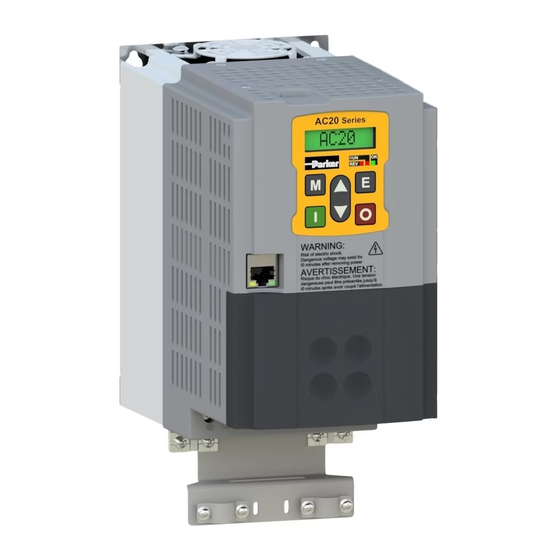
Parker AC20 Series Hardware Installation Manual
Variable speed drive
Hide thumbs
Also See for AC20 Series:
- Technical manual (58 pages) ,
- Technical manual (47 pages) ,
- Technical manual (46 pages)

Subscribe to Our Youtube Channel
Related Manuals for Parker AC20 Series


Summary of Contents for Parker AC20 Series
- Page 1 DOC-0017-04-EN: AC20 Series - Hardware Installation Manual AC20 Series DOC-0017-04-EN-A Variable Speed Drive 22.03.2023 Hardware Installation Manual 1 (154) DOC-0017-04-EN-A 22.03.2023...
-
Page 2: Safety Requirements
Parker Hannifin Manufacturing cannot accept responsibility for damage, injury, or expenses resulting there from. 1.1 Intended Users This manual is to be made available to all persons who are required to install, configure or service equipment described herein, or any other associated operation. -
Page 3: Hazards
DOC-0017-04-EN: AC20 Series - Hardware Installation Manual 1.5 Hazards Electric Shocks DANGER! Ignoring the following may result in injury: • This equipment can endanger life by exposure to rotating machinery and high voltages. • The equipment must be permanently earthed due to the high earth leakage current, and the inverter motor must be connected to an appropriate safety earth. -
Page 4: Safety & Emc Requirements
DOC-0017-04-EN: AC20 Series - Hardware Installation Manual Safety & EMC Requirements Where there is a conflict between safety and EMC requirements, personnel safety shall always take precedence. Safety WARNING! Ignoring the following may result in injury or damage to equipment: •... -
Page 5: Application Risk & Risk Assessment
• The specifications, processes and circuitry described herein are for guidance only and may need to be adapted to the user’s specific application. • Parker cannot guarantee the suitability of the equipment described in this Manual for individual applications. Risk Assessment CAUTION! •... -
Page 6: Manufacturing Location
Parker Hannifin Manufacturing Germany GmbH & Co KG - Sitz: Bielefeld - Amtsgericht: Bielefeld HRA 15699 Partner liable to unlimited extent: Parker Hannifin GmbH, Sitz Bielefeld, Amtsgericht Bielefeld HRB 35489 Geschäftsführung der PARKER Hannifin GmbH: Dr.-Ing. Hans-Jürgen Haas, Kees Veraart, Chairman of the board: Dr.-Ing. Gerd Scheffel 6 (154) -
Page 7: Table Of Contents
DOC-0017-04-EN: AC20 Series - Hardware Installation Manual 3 Table of Contents Safety Requirements ........................... 2 Intended Users ..........................2 Application Area .......................... 2 Personnel ............................ 2 Product Warnings, Cautions and Information notices ..............2 Hazards ............................3 Electric Shocks ............................. 3 Safety &... - Page 8 DOC-0017-04-EN: AC20 Series - Hardware Installation Manual Dynamic Braking Resistor ......................63 Resistor Power Requirement Calculation ....................63 Resistor Selection ............................63 Resistor Protection Devices ........................64 AC Motor Choke ........................65 1ø, 230V Products ............................65 3ø, 230V Products ............................66 3ø, 400V Products ............................
- Page 9 DOC-0017-04-EN: AC20 Series - Hardware Installation Manual 11.3 North American & Canadian Compliance ................133 North American Compliance ........................133 Canadian Compliance ..........................133 North American & Canadian Compliance Information ................133 11.4 Environmental Compliance ..................... 135 REACH (Restriction, Evaluation, Authorisation & Restriction of Chemicals) ..........135 RoHS (Restriction of Hazardous Substances) ...................
-
Page 10: Introduction
4.1 About this Hardware Installation Manual Users This Manual is intended for use by the installer of the AC20 series Inverters. It assumes a reasonable level of understanding in this discipline. There is a separate Software Reference Manual – DOC-0017-13 “AC20 Series – Software Reference Manual”, that is intended for use by the user and programmer of the AC20 series Inverters. -
Page 11: Initial Steps
DOC-0017-04-EN: AC20 Series - Hardware Installation Manual Initial Steps Use this Hardware Installation Manual to help plan the following: 1. Installation Know your requirements: Certification, i.e. CE, UL, CUL compliance (Chapter 11: Compliance). Conformance to local installation requirements. Supply and Cabling requirements (Chapter 6: Installation). -
Page 12: Product Overview
DOC-0017-04-EN: AC20 Series - Hardware Installation Manual 5 Product Overview General Overview: 1.5 – 180kW Power Range: 9 (Sizes 2 – 10) Frame Sizes: 1ø 220 – 240Vac ±10%, (Frame 2: 1.5 – 2.2kW) 3ø 220 – 240Vac ±10%, (Frames 2 - 5: 1.5 – 11kW) Power Supply: 3ø... - Page 13 DOC-0017-04-EN: AC20 Series - Hardware Installation Manual General Power Stack Features: Minimum: 1kHz Default: Frames 2 – 6: 4kHz Frame 7: 3kHz Frames 8 – 10: 2kHz Maximum: Frames 2 – 6 (1.5 – 37kW): 10kHz Switching Frequency: Frame 6 (45kW): 6kHz Frame 7: 8kHz Frames 8 –...
- Page 14 DOC-0017-04-EN: AC20 Series - Hardware Installation Manual Skip frequencies with adjustable skip band width Skip Frequencies: User selectable preset speeds Preset Speeds: Ramp, Coast, DC Injection, Fast Stop Stopping Modes: Symmetric or asymmetric ramp up and down rates Linear & S Ramps:...
-
Page 15: Installation
DOC-0017-04-EN: AC20 Series - Hardware Installation Manual 6 Installation IMPORTANT Please ensure that you have read and are familiar with the ‘Compliance’ chapter before installing the unit. 6.1 Mechanical Product Dimensions & Weights Frames 2 – 6: Product Dimensions Frame... - Page 16 DOC-0017-04-EN: AC20 Series - Hardware Installation Manual Frames 7 – 10: Product Dimensions Frame Size Weight 630.0 623.5 355.0 265.0 36.0 (24.80) (24.55) (13.98) (10.43) (79.37) 765.0 755.0 406.0 300.0 52.0 (30.12) (29.72) (15.98) (11.81) (114.64) 765.0 778.0 510.0 326.0 83.0...
-
Page 17: Product Fixing Dimensions
DOC-0017-04-EN: AC20 Series - Hardware Installation Manual Product Fixing Dimensions Fixing Dimensions Slot Size Frame Size Fixings 170.0 94.0 (6.69) (0.20) (3.70) (0.28) (0.20) (0.09) (0.19) 225.0 126.0 (8.86) (0.26) (4.96) (0.31) (0.24) (0.12) (0.21) 255.0 146.0 (10.04) (0.20) (5.75) (0.30) -
Page 18: Lifting The Inverter
DOC-0017-04-EN: AC20 Series - Hardware Installation Manual Lifting the Inverter CAUTION! HEAVY OBJECT Always ensure that all lifting equipment is suitably sized to support the weight of the product. These models are heavy and will require the use of a forklift or hoist to lift and install it into position. -
Page 19: Mounting The Inverter
DOC-0017-04-EN: AC20 Series - Hardware Installation Manual Mounting the Inverter These products are intended to be mounted vertically inside a suitable enclosure. 1. Mark out the fixing hole positions on the cubicle back panel as per the Fixing Dimensions listed in the table above. -
Page 20: Ventilation Clearance Requirements
DOC-0017-04-EN: AC20 Series - Hardware Installation Manual Ventilation Clearance Requirements The inverter gives off heat in normal operation and must therefore be mounted to allow the free flow of air through the ventilation slots and heatsink: Maintain minimum clearances for ventilation as given in the tables below to ensure adequate cooling of the inverter, and that heat generated by other adjacent equipment is not transmitted to the inverter. - Page 21 DOC-0017-04-EN: AC20 Series - Hardware Installation Manual Frames 7 – 10: Minimum Air Clearance for Product: Frame 7 is shown for illustration only. Forced Air (Fr 10 only) Forced Air Flow Product Clearances Frame Size 10.0 200.0 200.0 50.0 (0.39) (7.87)
-
Page 22: Wiring Bracket (Frames 2 - 5)
DOC-0017-04-EN: AC20 Series - Hardware Installation Manual Wiring Bracket (Frames 2 – 5) Wiring brackets are supplied with the AC20 product range (Frames 2-5 only). These brackets support the cabling to and from the drive, as well as providing a convenient means to achieve a 360° connection to the cable screen. -
Page 23: Electrical
DOC-0017-04-EN: AC20 Series - Hardware Installation Manual 6.2 Electrical IMPORTANT Please ensure that you have read and are familiar with the ‘Safety’ chapter before proceeding with the electrical installation. DANGER! RISK OF ELECTRIC SHOCK Terminal covers, main covers, and cover fixings must remain in place while the drive is energised. - Page 24 DOC-0017-04-EN: AC20 Series - Hardware Installation Manual Frames 3 & 4: Label Description Protective Earth Supply Input Phase L1 Supply Input Phase L2 Supply Input Phase L3 DC+ / Dynamic Brake Resistor Connection (+) Dynamic Brake Resistor Connection (-) Motor Output Phase U...
- Page 25 DOC-0017-04-EN: AC20 Series - Hardware Installation Manual Frame 6: Label Description Protective Earth Supply Input Phase L1 Supply Input Phase L2 Supply Input Phase L3 DC+ / Dynamic Brake Resistor Connection (+) Dynamic Brake Resistor Connection (-) Motor Output Phase U...
- Page 26 DOC-0017-04-EN: AC20 Series - Hardware Installation Manual Frames 9 & 10: Label Description DC+ / Dynamic Brake Resistor Connection (+) Dynamic Brake Resistor Connection (-) Supply Input Phase L1 Supply Input Phase L2 Supply Input Phase L3 Motor Output Phase U...
- Page 27 DOC-0017-04-EN: AC20 Series - Hardware Installation Manual Lower Terminal Cover Removal (Frames 6 – 10) On the Frames 6 – 10, the lower terminal cover must be removed to gain access to the power terminals for wiring. Frame 6: 1. Remove the two fixing screws from the bottom edge of the lower terminal cover.
- Page 28 DOC-0017-04-EN: AC20 Series - Hardware Installation Manual Frames 7 – 10: 1. Unscrew the 2x (Fr 7-9) / 4x (Fr 10) lower panel fixings. 2. Lift the panel away from the product to access the power terminals. 28 (154) DOC-0017-04-EN-A 22.03.2023...
- Page 29 DOC-0017-04-EN: AC20 Series - Hardware Installation Manual Terminal Block Guards (Frames 6 – 10) The Frame 6 – 10 products have an additional protective guard on the power terminal blocks that must be temporarily removed out of the way when wiring the drive.
- Page 30 DOC-0017-04-EN: AC20 Series - Hardware Installation Manual DC Link / AC Line Input Brake Output Terminals Terminals Motor Output Earth Chassis Earth Terminals Terminal Clamp Frame (L1/L, L2/N, (DC+, DC-, Size DBR) (U, V, W) (PE) (PE) M8 screw, accepting crimps or lugs up to 20mm wide M6 Fork Crimp (Maximum conductor size 25.0mm...
- Page 31 DOC-0017-04-EN: AC20 Series - Hardware Installation Manual 3ø, 400V Products: DC Link / Brake AC Line Input Output Motor Output Motor Terminals Terminals Terminals Frame Power Size Product Code (kW) (L1/L, L2/N, L3) (DC+, DC-, DBR) (U, V, W) Terminal Block Wire Range: 10 – 30 AWG 20G-42-0040...
- Page 32 DOC-0017-04-EN: AC20 Series - Hardware Installation Manual 400V Products: DC Link / AC Line Input Brake Output Terminals Terminals Motor Output Earth Chassis Earth Terminals Terminal Clamp Frame (L1/L, L2/N, (DC+, DC-, Size DBR) (U, V, W) (PE) (PE) 1.13 (10.0) 1.13 (10.0)
- Page 33 DOC-0017-04-EN: AC20 Series - Hardware Installation Manual Cable Connections With Wiring Bracket Fitted (Frames 2 – 5) Below is an example of how to correctly terminate the motor screen onto the wiring bracket: Motor earth connected to Supply earth chassis earth connected to clamp.
- Page 34 DOC-0017-04-EN: AC20 Series - Hardware Installation Manual Main Duct Fan Supply Voltage Selection (Frames 9 & 10) When wiring up the drive, the customer must check that the Main Duct Fan supply voltage has been setup for the correct AC Line voltage. This is done by checking the ‘Jumper’ link positions on the Fan Voltage Selection PCB: 1.
- Page 35 DOC-0017-04-EN: AC20 Series - Hardware Installation Manual Y-Capacitors & VDR Earth Disconnects The AC20 products are fitted with EMC filter capacitors connected between ‘live’ AC Line (and in some instances DC Link) circuits to earth. These capacitors are referred to as Y-Capacitors.
- Page 36 DOC-0017-04-EN: AC20 Series - Hardware Installation Manual 3ø, 400V Products: Motor J1 ‘EMC’ (AC CN5 ‘P -> PE’ Frame Power Line Y-Cap) Y1 ‘VAR’ (VDR) (DC Link Y-Cap) Size Product Code (kW) Link: Link: Link: 20G-42-0040... 20G-42-0065... ...
- Page 37 DOC-0017-04-EN: AC20 Series - Hardware Installation Manual Frame 6: AC Line Y-Cap Screws (x2) Y1 ’VAR’ VDR Link To access the Y-Cap links: 1. Remove the Lower Terminal cover. 2. Remove the 2x screws from the product. To access the VDR link, it is necessary to open the product: 1.
-
Page 38: Control Board Wiring
DOC-0017-04-EN: AC20 Series - Hardware Installation Manual Control Board Wiring DANGER! RISK OF ELECTRIC SHOCK Terminal covers, main covers, and cover fixings must remain in place while the drive is energised. These should only ever be removed once the supply to the unit and/or system has been disconnected, and the residual energy in the DC link capacitors has been discharged. - Page 39 DOC-0017-04-EN: AC20 Series - Hardware Installation Manual Terminal Identifications Frames 2 – 5: Terminal Ident Description RL1A Relay Output 1 (Contact A) RL1B Relay Output 1 (Contact B) RL2A Relay Output 2 (Contact A) RL2B Relay Output 2 (Contact B)
- Page 40 DOC-0017-04-EN: AC20 Series - Hardware Installation Manual Frames 6 – 10: Terminal Ident Description RL1A Relay Output 1 (Contact A) RL1B Relay Output 1 (Contact B) RL2A Relay Output 2 (Contact A) RL2B Relay Output 2 (Contact B) Motor Thermistor Input Motor Thermistor Input Analogue Input 1 (±10V, 0-10V, 0-20mA, 4-20mA)
- Page 41 DOC-0017-04-EN: AC20 Series - Hardware Installation Manual Wiring Example ↑ Configuration Setup: RL1A 110-230Vac (or 24Vdc) voltage supply. RL1B Relay output (to lamp). Motor Thermistor ‘+’ connection. Motor Thermistor ‘-’ connection. 0-10V variable input (from potentiometer) 4-20mA variable input (from current source)
- Page 42 DOC-0017-04-EN: AC20 Series - Hardware Installation Manual Recommended Wire & Ferrule Sizes The following wire sizes and ferrules are recommended for use with the control board terminal blocks: Maximum Bare Wire / Ferrule Wire Type Wire Size Ferrule Details Length 1x 1.0mm...
-
Page 43: Control Board Communications Wiring
DOC-0017-04-EN: AC20 Series - Hardware Installation Manual Control Board Communications Wiring The Ethernet communications socket allows users to: Communicate over Ethernet IP, Modbus TCP/IP, or ProfinetIO. Access the drive’s Web Server. Connect to the Drive System Explorer (DSE Lite) software for function block programming of custom applications and firmware updates, etc. - Page 44 DOC-0017-04-EN: AC20 Series - Hardware Installation Manual On Frames 6 – 10, the lower terminal cover will need to be removed prior to connecting the Ethernet cable into the RJ45 socket on the control PCB. 1. Insert the cable connector, clip side up, into the RJ45 port on control PCB.
-
Page 45: Option Cards
DOC-0017-04-EN: AC20 Series - Hardware Installation Manual 6.3 Option Cards Two types of Option Card are available, providing additional product functionality. Order Codes Order Code Description 2004-IO-00 General Purpose Input/Output (GPIO) option card 2004-EN-00 Encoder Feedback option card Installation DANGER! - Page 46 DOC-0017-04-EN: AC20 Series - Hardware Installation Manual 1. Remove the option card from its packaging. 2. Use the alignment rib in the control module housing and the option card fixing positions to correctly align the option card connector onto the control board header.
-
Page 47: Wiring
DOC-0017-04-EN: AC20 Series - Hardware Installation Manual 1. Remove the option card from its packaging. 2. Use the option card fixing positions to correctly align the option card connector onto the control board header. When aligned, push the Option Card down until it rests on the fixing and support pillars. - Page 48 DOC-0017-04-EN: AC20 Series - Hardware Installation Manual General Purpose Input / Output (GPIO): Firmware Identification Terminal Ident Slot 1 Slot 2 Description Anin 3 Anin 5 Analogue Input 3 / 5 (±10V, 0-10V) Anin 4 Anin 6 Analogue Input 4 / 6 (±10V, 0-10V)
- Page 49 DOC-0017-04-EN: AC20 Series - Hardware Installation Manual GPIO: +24V Configuration Example: ±10V Variable Input (from potentiometer) 0-10V Variable Input (from potentiometer) 0-10V Variable Output (to voltmeter) DX11 +24V Output (to relay coil) Terminal Block Wire Range The control board terminal wire range is as follows: Terminal Wire Range 0.2mm...
-
Page 50: Communication Interface Option Cards
DOC-0017-04-EN: AC20 Series - Hardware Installation Manual 6.4 Communication Interface Option Cards Communication Interface Option Cards are available to customers, providing a wider range of product compatible communication interfaces to end applications. Order Codes Order Code Description 2003-CB-00 CANopen communication interface option card... - Page 51 DOC-0017-04-EN: AC20 Series - Hardware Installation Manual 3. Unhook the bottom of the control module housing from the power stack. 4. Gently turn the control module upside down so it rests to the right of the power stack, with the interface cables still connected.
- Page 52 DOC-0017-04-EN: AC20 Series - Hardware Installation Manual 6. Remove the Comms Interface Option card from its packaging. 7. Slide the Comms Card along the PCB using the connector features for alignment. Note: The front facia of the Option should be loose at this point.
- Page 53 DOC-0017-04-EN: AC20 Series - Hardware Installation Manual Frames 6 – 10: On Frames 6 – 10, the lower terminal cover will need to be removed prior to option card installation. 1. Remove the Comms Interface Option card from its packaging.
-
Page 54: Μsd Memory Card
DOC-0017-04-EN: AC20 Series - Hardware Installation Manual 6.5 µSD Memory Card Commercially available µSD Memory Cards may be fitted to allow users to: Clone drive applications and archive files for duplication or copying to a replacement unit. Provide a quick and easy means of updating the drive firmware in the field. - Page 55 DOC-0017-04-EN: AC20 Series - Hardware Installation Manual Frames 6 – 10: On Frames 6 – 10, the lower terminal cover will need to be removed prior to µSD card installation in the control PCB. 1. Insert the µSD Card label side up...
-
Page 56: Remote Mounted 6901 Mmi
DOC-0017-04-EN: AC20 Series - Hardware Installation Manual 6.6 Remote Mounted 6901 MMI In addition to the Drive mounted keypad, there is a RJ11 port available to the user for connecting a remote mounted 6901 MMI. This 6901 can be useful when performing commissioning functions, or when a 6901 MMI is to be mounted remotely, i.e., on the door of a control cubicle. -
Page 57: Cable Connection
DOC-0017-04-EN: AC20 Series - Hardware Installation Manual Cable Connection Frames 2 – 5: On Frames 2 – 5, the control module terminal cover will need to be removed prior to connecting the remote 6901 MMI cable. 1. Insert the cable connector clip side down into the RJ11 port on the front of the product. - Page 58 DOC-0017-04-EN: AC20 Series - Hardware Installation Manual Frames 6 – 10: On Frames 6 – 10, the lower terminal cover will need to be removed prior to connecting the remote 6901 MMI cable into the control PCB. 1. Insert the cable connector...
-
Page 59: Associated Equipment
DOC-0017-04-EN: AC20 Series - Hardware Installation Manual 7 Associated Equipment Additional mandatory equipment is required when installing an inverter (i.e., AC Line Input Fuses), as well as optional components that may be specific to the installation (i.e., Input Chokes, EMC Filters, Output... -
Page 60: Ac Line Fuses
DOC-0017-04-EN: AC20 Series - Hardware Installation Manual 7.1 AC Line Fuses Line input fuse ratings are given in the tables below for both European and North American & Canada territories. For North America, the recommended fuses are either Mersen A60Q series, 600Vac/dc semiconductor protection fuses or Mersen A50QS series, 500Vac/dc semiconductor protection fuses. -
Page 61: External Emc Filter
An External AC Line Choke may be required on the line supply to the drive: 1. On supplies delivering >12kA but <50kA RMS symmetrical Amperes, 480V maximum. 2. To mitigate supply quality issues. Where required, Parker suggest the following AC Line Choke ratings: 1ø, 230V Products Motor... -
Page 62: 3Ø, 400V Products
DOC-0017-04-EN: AC20 Series - Hardware Installation Manual 3ø, 400V Products Motor Peak Current Frame Power Inductance Rated Current @150% HD Size Product Code (kW) (mH/phase) Rating (A) 20G-42-0040... 4.411 20G-42-0065... 2.940 20G-42-0090... 2.005 20G-43-0120... 1.575 20G-43-0170... 1.192 20G-44-0230... 0.919 20G-44-0320... -
Page 63: Dynamic Braking Resistor
Dynamic Brake Resistors should be used when an application requires regenerated power from the motor to be dissipated, usually during motor deceleration. The AC20 Series products are all fitted with an internal brake switch as standard, ready for connection to an external Dynamic Brake Resistor. -
Page 64: Resistor Protection Devices
DOC-0017-04-EN: AC20 Series - Hardware Installation Manual Parker recommends the use of cubicle mount metal clad resistors and offer an optimised range, specified below: Power Rating Resistance Continuous Current Order Code (Ω) Rating (A) CZ467715 CZ467714 CZ389853 CZ467717 CZ388397 CZ463068... -
Page 65: Ac Motor Choke
2. Eliminates potential nuisance overcurrent trips in installations with long motor cable runs. 3. Limits parasitic capacitance flowing to earth. Refer to ‘Chapter 11: Compliance’ for maximum motor cable lengths. Where a choke is deemed necessary, Parker suggest the following AC Motor Choke ratings: 1ø, 230V Products Motor... -
Page 66: 3Ø, 230V Products
DOC-0017-04-EN: AC20 Series - Hardware Installation Manual 3ø, 230V Products Motor Frame Power Inductance Rated Current Peak Output Size Product Code (kW) (mH/phase) Current (A) 20G-32-0070... 1.006 20G-32-0100... 0.704 20G-33-0170... 0.414 20G-34-0210... 0.335 20G-35-0300... 0.235 20G-35-0400... 0.176 Notes: AC Motor Choke inductance values calculated @230V, 60Hz... -
Page 67: Calculation
DOC-0017-04-EN: AC20 Series - Hardware Installation Manual Calculation The choke ratings listed above are for guidance only. Customers may want to calculate their own ratings using the formula below: ���������������� ���� � × � √3 ���� = ÷ ( 2���� × ���������������� ) ����... -
Page 68: Safe Torque Off (Sto): Sil2, Pld
DOC-0017-04-EN: AC20 Series - Hardware Installation Manual 8 Safe Torque Off (STO): SIL2, PLd 8.1 Overview Introduction The AC20 is an adjustable speed electrical power drive system that is suitable for safety related applications (PDS(SR)). The drive is used in typical applications such as pump controls, packaging machines, textile machines, printing machines, or material forming machines. -
Page 69: Sto Functional Description
DOC-0017-04-EN: AC20 Series - Hardware Installation Manual STO Functional Description STO is a means of preventing an inverter from delivering rotational force to its connected electric motor. Please refer to EN61800-5-2:2017 para 4.2.3.2 for the formal definition. To ensure a high degree of safety, two independent STO control channels are implemented in hardware, providing the safety sub function STO. -
Page 70: En61800-5-2:2017 (Adjustable Speed Electrical Power Drive Systems) & En61508:2010
DOC-0017-04-EN: AC20 Series - Hardware Installation Manual 2. General Requirements of Category 3: A single failure will not lead to loss of the STO safety function. Failure of more than one component can lead to the loss of the STO safety function. -
Page 71: Emc
DOC-0017-04-EN: AC20 Series - Hardware Installation Manual In addition to the mandatory requirements of EN61800-3, the STO functionality has been subjected to testing for immunity at higher levels. In particular, the STO function (only) has been tested for radiated immunity according to EN61800-5-2:2017 Annex E up to 6GHz which includes frequencies used by mobile transmitters in general. -
Page 72: Input State Truth Table
The user / installer is responsible for designing a suitable system to meet all requirements of the application including assessing and validating it. Parker will not accept any liability for failure to do this or any consequential loss or damage. - Page 73 DOC-0017-04-EN: AC20 Series - Hardware Installation Manual Configuration Setup: Motor Thermistor ‘+’ connection Motor Thermistor ‘-’ connection Run Forward: 24V digital input STOA 24V input connected i.e., STO DISABLED (drive operational) STOB 24V input connected i.e., STO DISABLED (drive operational) Minimum STO Implementation: This example shows ‘STO Request’...
- Page 74 DOC-0017-04-EN: AC20 Series - Hardware Installation Manual STO Implementation with a Door Switch (Stop Category 0): This example shows a safety door switch that is used to invoke STO on the drive when the safety door is ‘opened’, allowing access into the ‘Danger Zone’.
- Page 75 DOC-0017-04-EN: AC20 Series - Hardware Installation Manual SS1 / STO Implementation using a Safety Control Unit (Stop Category 1): The example below shows Safe Stop (SS1) implementation that brings a motor to rest in a controlled manner, before invoking STO on the drive after a time delay determined by an external Safety Control Unit.
- Page 76 DOC-0017-04-EN: AC20 Series - Hardware Installation Manual 3. Close the ‘Drive Start PB’ switch to run the drive. To stop the drive: 1. Open the ‘Drive Stop PB’ switch and wait for the motor to come to a standstill. To invoke STO: 1.
-
Page 77: Technical Specification
DOC-0017-04-EN: AC20 Series - Hardware Installation Manual Technical Specification STOA, STOB, referenced to 0V Terminal Idents: 24V PELV (with energy source class 3, according to IEC 62368-1) Nominal Input Voltage: 25.2V (26.4V in a maximum operating ambient of 40°C) Maximum Input Voltage: Recommended Input 0V –... - Page 78 STO function is a factory-fitted and factory-tested feature. Repairs to the inverter STO featured-product are to be carried out only by Parker authorised repair centres. Any unauthorised attempt to repair or disassemble the product will render any warranty null and void, and STO integrity could be impaired.
-
Page 79: Sto Functional Checks
DOC-0017-04-EN: AC20 Series - Hardware Installation Manual • The STO function must not be used for electrical isolation of the inverter and power. Whenever any personnel require to work on the drive, associated motor or other power items, they must always use recognised and suitable electrical isolation devices. -
Page 80: Comprehensive Checks
DOC-0017-04-EN: AC20 Series - Hardware Installation Manual Comprehensive Checks A comprehensive check of the STO function ensures the overall integrity of the STO functionality. It proves the independent operation of each channel individually (including during the normal dual channel operation), and the essential single fault detection. - Page 81 DOC-0017-04-EN: AC20 Series - Hardware Installation Manual STO Test Step Test Check or Activity Expected Reaction & Effect STO Channel A Check With the inverter running and the motor turning at SPT1, momentarily disconnect Motor must immediately coast to a rest.
-
Page 82: Test Protocol Specimen
DOC-0017-04-EN: AC20 Series - Hardware Installation Manual Test Protocol Specimen Project / Machine: ______________________ Name of Tester: ______________________ Reference of Inverter: ______________________ Successfully tested (Test steps 1 – 18) ☐ Functionality: Safe Stop 1: Successfully tested ☐ Is not used ☐... -
Page 83: Sto Troubleshooting
8.7 STO Troubleshooting The table below is for guidance only and may not be a comprehensive list of all possible symptoms relating to STO. Parker will not accept responsibility for any consequences arising from its incompleteness or inaccuracy. STO Input STO Input... -
Page 84: Basic Drive Operation
DOC-0017-04-EN: AC20 Series - Hardware Installation Manual 9 Basic Drive Operation 9.1 ‘Local’ Operation To run the drive using either the onboard keypad, or the 6901 remote keypad, the following steps need to be followed. Note: This sequence assumes that the power connections (ac line supply & motor output connections) have already been connected as per the installation instructions. -
Page 85: Onboard Drive Keypad & Display Overview
DOC-0017-04-EN: AC20 Series - Hardware Installation Manual Onboard Drive Keypad & Display Overview Keypad Overview Navigation / Parameter Edit Keys MENU Key Navigation - Displays the next Menu level, or the first parameter of the current Menu. Parameter - Allows a writable parameter to be modified (this is indicated by → appearing on the left of the bottom line). - Page 86 DOC-0017-04-EN: AC20 Series - Hardware Installation Manual Status Indicator LEDs ‘REV’ LED ‘RUN’ LED Inverter Status Inverter RUNNING in FORWARDS direction. Inverter STOPPING from FORWARDS direction. Inverter RUNNING in REVERSE direction. Inverter STOPPING from REVERSE direction. Inverter STOPPED. ‘OK’ LED Inverter Status Inverter is HEALTHY.
-
Page 87: 6901 Remote Keypad & Display Overview
DOC-0017-04-EN: AC20 Series - Hardware Installation Manual 6901 Remote Keypad & Display Overview 6901 Keypad Overview Navigation / Parameter Edit Keys UP Key Navigation - Moves upwards through the list of parameters. Parameter - Increments the value of the displayed parameter. - Page 88 DOC-0017-04-EN: AC20 Series - Hardware Installation Manual JOG Key Control - Runs the motor at a speed determined by the JOG SETPOINT parameter. When the key is released, the Inverter returns to the “STOPPED” state. Only operates when the inverter is “STOPPED“, and in Local Start/Stop mode.
-
Page 89: Keypad Menu Navigation Examples
DOC-0017-04-EN: AC20 Series - Hardware Installation Manual Keypad Menu Navigation Examples Below are some examples of how the keypad keys are used to navigate through the sub-menu lists: Navigate to Top Level Menu on Power-Up Onboard Keypad Display 6901 Remote Keypad Display VER 1.1.1... -
Page 90: Basic Drive Setup
Stop the drive: bring the motor back to a standstill. Change the motor direction: to run the motor in reverse. Note: By default, parameter value changes are saved automatically. Refer to the ‘AC20 Series Software Reference Manual’ (DOC-0017-13) for details. - Page 91 DOC-0017-04-EN: AC20 Series - Hardware Installation Manual Note: The parameters displayed in this list will vary depending on what settings have been selected i.e., ‘Motor Type’ & ‘Control Strategy’ parameters. Enter values as required (‘key’ parameters listed below only): Parameter Name...
- Page 92 DOC-0017-04-EN: AC20 Series - Hardware Installation Manual b) PMAC Motor To enter the ’Motor Data PMAC’ information for a PMAC Motor: Navigate to the ‘Motor Data PMAC’ sub-menu: Motor Nameplate Level Menu Overview Onboard Keypad Display / 6901 Remote Keypad Display...
- Page 93 DOC-0017-04-EN: AC20 Series - Hardware Installation Manual To enter the ’Encoder’ information: Navigate to the ‘Encoder’ (if option fitted in slot 1), or ‘Encoder 2’ (if option fitted in slot 2) sub- menu: Encoder Level Menu Overview Onboard Keypad Display / 6901 Remote Keypad Display...
- Page 94 DOC-0017-04-EN: AC20 Series - Hardware Installation Manual Once ‘Local’ Control Mode is enabled, the drive will show the following status indication: Local Control Mode ‘Enabled’ Onboard Keypad Display 6901 Remote Keypad Display No indication displayed. The ‘SEQ’ & ‘REF’ LEDs will illuminate.
- Page 95 DOC-0017-04-EN: AC20 Series - Hardware Installation Manual The drive should run through a pre-determined routine. When the ‘Autotune’ routine is running, the drive will show the following status indication: Drive ‘Running’ Indication Onboard Keypad Display 6901 Remote Keypad Display Motor ‘Running’ & ‘Stopped’ LEDs will flash and ‘RUN’...
- Page 96 DOC-0017-04-EN: AC20 Series - Hardware Installation Manual Press the ‘Run’ key: Local ‘Run’ Enable Onboard Keypad Display 6901 Remote Keypad Display The drive will enable and should accelerate the motor to the speed demanded. The ‘Speed Percent’ parameter provides the real time speed feedback (% of motor nameplate rpm) value.
- Page 97 DOC-0017-04-EN: AC20 Series - Hardware Installation Manual 5. To Change Motor Direction: To change the direction of the motor with the onboard keypad: Ensure the drive is in a ‘Stopped’ state: Press the ‘Stop’ key and either the ‘Up’ (Forward) or ‘Down’ (Reverse) key simultaneously:...
-
Page 98: Remote' Operation (Using Pre-Defined Macro's)
DOC-0017-04-EN: AC20 Series - Hardware Installation Manual 9.2 ‘Remote’ Operation (Using Pre-Defined Macro’s) To run the drive ‘remotely’ (using either push-buttons, switches or PLC’s as opposed to a keypad), the following steps need to be followed. Note: This sequence assumes that the ‘Basic Drive Setup’ routine has been completed, as outlined above. -
Page 99: Running The Drive
DOC-0017-04-EN: AC20 Series - Hardware Installation Manual Select an ‘Application’ (Macro) by changing the value of the ‘Application’ parameter. Next, change the ‘Load Application’ parameter ‘FALSE’ to ‘TRUE’. Parameter Name Default Value Range Units Type Writable Application 1150 9: Saved... -
Page 100: Application '1': Standard (Basic Speed Control)
DOC-0017-04-EN: AC20 Series - Hardware Installation Manual Application ‘1’: Standard (Basic Speed Control) This Application is ideal for general purpose applications. It provides push-button or switched start/stop control. The setpoint is the sum of the two analogue inputs AIN1 and AIN2, providing Speed Setpoint + Speed Trim capability. -
Page 101: Application '2': Auto / Manual
DOC-0017-04-EN: AC20 Series - Hardware Installation Manual Application ‘2’: Auto / Manual Two Run inputs and two Setpoint inputs are provided. The Auto/Manual switch selects which pair of inputs is active. The Application is sometimes referred to as Local/Remote. ↑... -
Page 102: Application '3': Presets
DOC-0017-04-EN: AC20 Series - Hardware Installation Manual Application ‘3’: Presets This is ideal for applications requiring multiple discrete speed levels. The setpoint is selected from either the sum of the analogue inputs, (as in Application 1 and known here as PRESET 0), or as one of up to seven other pre-defined speed levels. -
Page 103: Application '4': Raise / Lower
DOC-0017-04-EN: AC20 Series - Hardware Installation Manual Application ‘4’: Raise / Lower This Application mimics the operation of a motorised potentiometer. Digital inputs allow the setpoint to be increased and decreased between limits. The limits and ramp rate can be set using the keypad. -
Page 104: Application '5': Pid
DOC-0017-04-EN: AC20 Series - Hardware Installation Manual Application ‘5’: PID A simple application using a Proportional-Integral-Derivative 3-term controller. The setpoint is taken from AIN1, with feedback signal from the process on AIN2. The scale and offset features of the analogue input blocks may be used to correctly scale these signals. -
Page 105: Application '6': Aux Comms
DOC-0017-04-EN: AC20 Series - Hardware Installation Manual Application ‘6’: Aux Comms ↑ Configuration Setup: RL1A 110-230Vac (or 24Vdc) voltage supply RL1B Healthy: Relay output (to lamp) Motor Thermistor ‘+’ connection Motor Thermistor ‘-’ connection Remote Setpoint (%) – input 1: 0-10V variable input (from potentiometer) Remote Setpoint ‘Trim’... -
Page 106: External +24V Power-Up Mode
DOC-0017-04-EN: AC20 Series - Hardware Installation Manual 9.3 External +24V Power-Up Mode Allows for the partial power-up of the product without mains power applied, for programming of the drive using the DSELite programming tool through the Ethernet port, or communication with the drive through the Anybus Comms option. -
Page 107: Routine Maintenance & Repair
10.3 Repair In the event of a drive failure, the inverter should be returned to a local Parker Repair Centre. No attempt should be made by the user to repair the unit themselves. Only Parker trained personnel are permitted to repair this product in order to maintain certifications, reliability, and quality levels. -
Page 108: Compliance
11.2 European Compliance CE Marking The CE marking is placed upon the product by Parker Hannifin Manufacturing to facilitate its free movement within the European Economic Area (EEA). The CE marking provides a presumption of conformity to all applicable directives. Harmonized standards are used to demonstrate compliance with the essential requirements laid down in those relevant directives. - Page 109 DOC-0017-04-EN: AC20 Series - Hardware Installation Manual WARNING! Local wiring regulations always take precedence. Where there are any conflicts between regulatory standards - for example, earthing requirements for electromagnetic compatibility, safety shall always take precedence. Low Voltage Directive When installed in accordance with this manual, the product will comply with the low voltage directive 2014/35/EU.
-
Page 110: Emc Compliance
DOC-0017-04-EN: AC20 Series - Hardware Installation Manual EMC Compliance A list of EMC Compliance definitions relevant to this section are listed in the table below: Terminology Description Environment Environment that includes domestic premises, it also includes establishments directly connected without transformers to a low-voltage power supply First Environment: network which supplies buildings used for domestic purposes. - Page 111 DOC-0017-04-EN: AC20 Series - Hardware Installation Manual Standards Limits* Product Generic Specific Frequency (MHz) dB(µV/m) EN 61800-3 EN61000-6-3 EN61000-6-4 These limits have no 30 - 230 Category C3 relationships with the generic 230 - 1000 standards. * = Limit has been adjusted for a measurement distance of 10m.
- Page 112 DOC-0017-04-EN: AC20 Series - Hardware Installation Manual Radiated & Conducted Emissions: Compliance Overview WARNING! In a domestic environment, this product may cause radio interference, in which case supplementary mitigation measures may be required. EN 61800-3 Category C1 Category C2 Category C3...
- Page 113 DOC-0017-04-EN: AC20 Series - Hardware Installation Manual 1ø, 230V Products: Frame 2 Quasi Freq Limit Margin Peak (MHz) (dB/µV) (dB/µV) (dB/µV) (dB/µV) 0.154 81.99 90.00 8.01 0.190 96.39 100.00 3.61 0.213 80.07 90.00 9.93 0.217 99.30 100.00 0.70 0.461 69.30 90.00...
- Page 114 DOC-0017-04-EN: AC20 Series - Hardware Installation Manual Frame 4 Quasi Freq Limit Margin Peak (MHz) (dB/µV) (dB/µV) (dB/µV) (dB/µV) 0.194 86.74 90.00 3.26 0.198 96.33 100.00 3.67 0.225 86.27 90.00 3.73 0.225 93.91 100.00 6.09 1.285 73.82 86.00 12.18 1.291 67.87...
- Page 115 DOC-0017-04-EN: AC20 Series - Hardware Installation Manual Frame 3 Quasi Freq Limit Margin Peak (MHz) (dB/µV) (dB/µV) (dB/µV) (dB/µV) 0.162 81.79 90.00 8.21 0.162 96.38 100.00 3.62 0.221 93.81 100.00 6.19 0.273 80.84 90.00 9.16 0.529 84.01 86.00 1.99 0.661 74.11...
- Page 116 DOC-0017-04-EN: AC20 Series - Hardware Installation Manual Frame 7 Quasi Freq Limit Margin Peak (MHz) (dB/µV) (dB/µV) (dB/µV) (dB/µV) 0.154 113.17 120.00 6.83 0.158 121.63 130.00 8.37 0.213 108.90 120.00 11.10 0.225 116.29 130.00 13.71 0.497 98.99 120.00 21.01 0.617 107.54...
-
Page 117: Emc Installation Guidance
RF impedance of the local earth connection. When installing an AC20 in control cubicle, Parker recommends using a star-point earthing method where ‘noisy’ and ‘clean’ earths are separated out. Four separate earth bus bars, three of which are insulated from... - Page 118 DOC-0017-04-EN: AC20 Series - Hardware Installation Manual 1. Clean Earth Busbar (insulated from the mounting panel): Used as a reference point for all signal and control cabling. It may be further subdivided into an analog and a digital reference busbar, each separately connected to the star earthing point.
- Page 119 DOC-0017-04-EN: AC20 Series - Hardware Installation Manual Cabling Requirements Cables used for connecting to inverters, can be termed as electrically ‘Clean’, ‘Noisy’ or ‘Sensitive’. The diagram below shows an overview: AC Line Fuses EMC Filter (optional) AC Line Choke (optional) Dynamic Braking Resistor (optional) Signal, Control &...
- Page 120 DOC-0017-04-EN: AC20 Series - Hardware Installation Manual Cable routing should be planned in a way that segregates certain cable types to meet EMC compliance: Use the shortest possible motor cable lengths. When connecting multiple motors to a single inverter, use a star junction point for motor cable connections.
- Page 121 DOC-0017-04-EN: AC20 Series - Hardware Installation Manual 2. Additive Emissions Emissions from individual components tend to be additive. To reduce the emissions: The equipment must be mounted in a metal cubicle. Refer to ‘Radiated & Conducted Emissions: Compliance Overview’ section above.
- Page 122 DOC-0017-04-EN: AC20 Series - Hardware Installation Manual Issues arising from long Motor Cable runs Because cable capacitance and hence conducted emissions increase with motor cable length, conformance to EMC limits is only guaranteed up to a maximum cable length as specified in the table in the ‘Cabling Requirement’...
-
Page 123: Harmonic Information
DOC-0017-04-EN: AC20 Series - Hardware Installation Manual Harmonic Information 1ø, 230V Products Drive Type: 3ø, Fundamental Voltage = 230V Line Inductance = 84µH, PSCC = 5kA The 1.5kW is designated as “Professional Equipment” as defined in EN61000-3-2. Frame Size: Product Code: 20G-12-0070... - Page 124 DOC-0017-04-EN: AC20 Series - Hardware Installation Manual 3ø, 230V Products Drive Type: 3ø, Fundamental Voltage = 230V Line Inductance = 84µH, PSCC = 5kA The Frame 2’s are designated as “Professional Equipment” as defined in EN61000-3-2. Frame Size: Product Code: 20G-32-0070...
- Page 125 DOC-0017-04-EN: AC20 Series - Hardware Installation Manual Drive Type: 3ø, Fundamental Voltage = 230V Line Inductance = 84µH, PSCC = 5kA Frame Size: Product Code: 20G-34-0210... 20G-35-0300... 20G-35-0400... Power Rating (kW): Current Rating (A): Harmonic No. RMS Current (A) 20.04 29.14...
- Page 126 DOC-0017-04-EN: AC20 Series - Hardware Installation Manual 3ø, 400V Products Drive Type: 3ø, Fundamental Voltage = 400V Line Inductance = 146µH, PSCC = 5kA These products are designated as “Professional Equipment” as defined in EN61000-3-2. Frame Size: Product Code: 20G-42-0040...
- Page 127 DOC-0017-04-EN: AC20 Series - Hardware Installation Manual Drive Type: 3ø, Fundamental Voltage = 400V Line Inductance = 146µH, PSCC = 5kA The Frame 3’s are designated as “Professional Equipment” as defined in EN61000-3-2. Frame Size: Product Code: 20G-43-0120… 20G-43-0170... 20G-44-0230...
- Page 128 DOC-0017-04-EN: AC20 Series - Hardware Installation Manual Drive Type: 3ø, Fundamental Voltage = 400V Line Inductance = 146µH, PSCC = 5kA Frame Size: Product Code: 20G-44-0320... 20G-45-0380... 20G-45-0440... Power Rating (kW): 18.5 Current Rating (A): Harmonic No. RMS Current (A) 29.15...
- Page 129 DOC-0017-04-EN: AC20 Series - Hardware Installation Manual Drive Type: 3ø, Fundamental Voltage = 400V Line Inductance = 146µH, PSCC = 5kA Frame Size: Product Code: 20G-45-0600... 20G-46-0750… 20G-46-0900… Power Rating (kW): Current Rating (A): Harmonic No. RMS Current (A) 56.17 70.92...
- Page 130 DOC-0017-04-EN: AC20 Series - Hardware Installation Manual Drive Type: 3ø, Fundamental Voltage = 400V Line Inductance = 146µH, PSCC = 5kA Frame Size: Product Code: 20G-47-1100… 20G-47-1500… 20G-48-1800… Power Rating (kW): Current Rating (A): Harmonic No. RMS Current (A) 107.92 147.18...
- Page 131 DOC-0017-04-EN: AC20 Series - Hardware Installation Manual Drive Type: 3ø, Fundamental Voltage = 400V Line Inductance = 146µH, PSCC = 5kA Frame Size: Product Code: 20G-48-2200… 20G-48-2650… 20G-49-3200… Power Rating (kW): Current Rating (A): Harmonic No. RMS Current (A) 210.98 254.93...
- Page 132 DOC-0017-04-EN: AC20 Series - Hardware Installation Manual Drive Type: 3ø, Fundamental Voltage = 400V Line Inductance = 146µH, PSCC = 5kA Frame Size: Product Code: 20G-410-3600… Power Rating (kW): Current Rating (A): Harmonic No. RMS Current (A) 350.04 0.02 79.71 22.93...
-
Page 133: North American & Canadian Compliance
DOC-0017-04-EN: AC20 Series - Hardware Installation Manual 11.3 North American & Canadian Compliance North American Compliance This product is certified under the US governments Occupational Safety and Health Administration’s (OHSA), Nationally Recognised Testing Laboratory (NRTL) program. An NRTL is a private third-party organisation accredited by OSHA to test and certify products to national standards for compliance with North American requirements. - Page 134 DOC-0017-04-EN: AC20 Series - Hardware Installation Manual Motor over temperature sensing is provided by the product when an external temperature sensor (of type PTC or NTC) is connected to the motor thermistor input on the control board. Recommended Wire Sizes North American wire sizes (AWG) are based on NEC/NFPA-70 for ampacities of thermoplastic-insulated (75ºC) copper conductors.
-
Page 135: Environmental Compliance
Registration, Evaluation, Authorization, and Restriction of Chemicals (REACH) entered into force on June 1, 2007. Parker agrees with the purpose of REACH, which, is to ensure a high level of protection of human health and the environment. Parker is compliant with all applicable requirements of REACH. -
Page 136: Ac20 Series Product Codes
DOC-0017-04-EN: AC20 Series - Hardware Installation Manual 12 AC20 Series Product Codes Order example 0070 Device Family AC20 Series, Advanced, General Purpose AC Drive Voltage 230Vac, Single Phase 230Vac, Three Phase 400Vac, Three Phase 3 & 4 Frame Size and Current Rating (Heavy Duty) -
Page 137: Technical Information
DOC-0017-04-EN: AC20 Series - Hardware Installation Manual 13 Technical Information 13.1 General Product Ratings Environment 0°C to 40°C (derate output current above 40°C by 2% per °C, up to maximum of 45°C). Operating Temperature: Anybus Comms Option not suitable for use in temperatures >40°C. -
Page 138: Ac Line Fed Power Stack Ratings
DOC-0017-04-EN: AC20 Series - Hardware Installation Manual 13.2 AC Line Fed Power Stack Ratings 1ø, 230V Products Power Supply = 1ø 220-240V ±10%, 50/60Hz ±10%, PSCC = 5kA Motor power, output current and input current must not be exceeded under steady state operating conditions. -
Page 139: Internal Brake Switch Ratings
DOC-0017-04-EN: AC20 Series - Hardware Installation Manual Power Supply = 3ø 380-480V ±10%, 50/60Hz ±10%, PSCC = 5kA Motor power, output current and input current must not be exceeded under steady state operating conditions. Minimum repetitive power up / power down cycle time = 10 mins. -
Page 140: 3Ø, 400V Products
DOC-0017-04-EN: AC20 Series - Hardware Installation Manual 3ø, 400V Products DC Link Brake Switch Threshold = 764V Continuous Peak (Instant) Motor Brake Power Brake Power Resistor Frame Power Current Diss Current Diss Value Size Product Code (kW) (kW) (kW) (Ω) 20G-42-0040... -
Page 141: Analogue Outputs
DOC-0017-04-EN: AC20 Series - Hardware Installation Manual Analogue Outputs AO1, AO2, referenced to 0V Terminal Idents: Voltage Mode: 0 – 10V Type: Current Mode: 0 – 20mA Maximum Output 20mA Current: Voltage Mode: Max current = 20mA Load Impedance: Current Mode: Max voltage = 10V 2.5msec (0 to 90%) -
Page 142: Digital Outputs
DOC-0017-04-EN: AC20 Series - Hardware Installation Manual Digital Outputs DX1, DX2, DX3, referenced to 0V Terminal Idents: Nominal Output Voltage: Minimum Output 18V @ 50mA Voltage: Maximum Output 50mA (Each output, or Total outputs combined) Current: Isolated: Short Circuit Protection:... -
Page 143: External +24V Auxiliary Input
DOC-0017-04-EN: AC20 Series - Hardware Installation Manual External +24V Auxiliary Input Allows for the partial power-up of the product without mains power applied, for programming of the drive using the DSELite programming tool through the Ethernet port, or communication with the drive through the Anybus Comms option. -
Page 144: Encoder Feedback Option Card Ratings
DOC-0017-04-EN: AC20 Series - Hardware Installation Manual 13.5 Encoder Feedback Option Card Ratings Encoder Inputs A, /A, B, /B Terminal Idents: 5V to 24V Nominal Input Voltage: +/- 30V Maximum Input Voltage: Selectable: Low level = 1.8V (suitable for 5V TTL, RS422, RS485 level input... -
Page 145: Gpio Option Card Ratings
DOC-0017-04-EN: AC20 Series - Hardware Installation Manual 13.6 GPIO Option Card Ratings Analogue Inputs AI3, AI4, referenced to 0V Terminal Idents: Voltage Modes: ± 10V Type: 0 – 10V ± 30V Maximum Input Voltage: 10kΩ Input Impedance: 15 Bit Resolution:... -
Page 146: Digital Output
DOC-0017-04-EN: AC20 Series - Hardware Installation Manual Digital Output DX11, referenced to 0V Terminal Idents: Nominal Output Voltage: Minimum Output 18V @ 50mA Voltage: 50mA Note: Total consumption of all Base Control Board Digital Outputs DX1, Maximum Output Current: DX2, DX3, User +24V Output, and Option Card DX11 must not exceed 120mA. -
Page 147: Appendix A: Power Stack Circuit Overview
DOC-0017-04-EN: AC20 Series - Hardware Installation Manual Appendix A: Power Stack Circuit Overview 1ø, 230V Products Frame 2: 3ø, 230V Products Frame 2: DOC-0017-04-EN-A 22.03.2023 147 (154) - Page 148 DOC-0017-04-EN: AC20 Series - Hardware Installation Manual Frame 3: Frame 4: 148 (154) DOC-0017-04-EN-A 22.03.2023...
-
Page 149: 3Ø, 400V Products
DOC-0017-04-EN: AC20 Series - Hardware Installation Manual Frame 5: 3ø, 400V Products Frame 2: DOC-0017-04-EN-A 22.03.2023 149 (154) - Page 150 DOC-0017-04-EN: AC20 Series - Hardware Installation Manual Frame 3: 150 (154) DOC-0017-04-EN-A 22.03.2023...
- Page 151 DOC-0017-04-EN: AC20 Series - Hardware Installation Manual Frame 4: Frame 5: DOC-0017-04-EN-A 22.03.2023 151 (154)
- Page 152 DOC-0017-04-EN: AC20 Series - Hardware Installation Manual Frame 6: Frames 7 & 8: 152 (154) DOC-0017-04-EN-A 22.03.2023...
- Page 153 DOC-0017-04-EN: AC20 Series - Hardware Installation Manual Frame 9: Frame 10: DOC-0017-04-EN-A 22.03.2023 153 (154)
- Page 154 DOC-0017-04-EN: AC20 Series - Hardware Installation Manual 154 (154) DOC-0017-04-EN-A 22.03.2023...
Need help?
Do you have a question about the AC20 Series and is the answer not in the manual?
Questions and answers