
Subscribe to Our Youtube Channel
Related Manuals for Parker E-DC


Summary of Contents for Parker E-DC
- Page 1 88-020714-01 A Automation E-DC Drive Hardware Installation Guide Effective: May 22, 2002...
- Page 2 E Series products and the information in this user guide are the proprietary property of Parker Hannifin Corporation or its licensers, and may not be copied, disclosed, or used for any purpose not expressly authorized by the owner thereof.
-
Page 3: Table Of Contents
Table of Contents Chapter 1 – Introduction ..........................5 E-DC Drive – Description ........................6 Compatible Motors ..........................7 Chapter 2 – Installation ..........................9 What You Should Have (ship kit) ......................10 Installation Overview ......................... 10 Automatic Test ............................12 Test Setup with Controller ........................17 Installation ............................ - Page 4 E-DC Hardware Installation Guide...
-
Page 5: Chapter 1 - Introduction
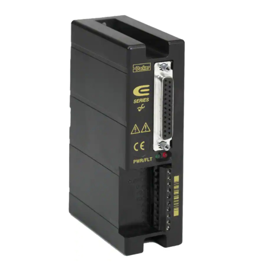
C H A P T E R O N E Introduction IN THIS CHAPTER • E-DC Drive Description • Compatible Motors • Compumotor Products E-DC Hardware Installation Guide Chapter 1 – Introduction... - Page 6 E-DC D – D RIVE ESCRIPTION The E-DC Drive is a microstepping drive that runs two-phase step motors. It operates from an external DC power supply, in the range of 24 - 48VDC. A typical system is shown below. SERIES...
-
Page 7: Compatible Motors
ESONANCE All step motors are subject to resonance, and to ringing after quick tran- sient moves. The E-DC Drive has an anti-resonance circuit. This is a general purpose damping circuit that provides aggressive and effective damping. Anti-resonance can be disabled with a DIP switch. - Page 8 E-DC Hardware Installation Guide Chapter 1 – Introduction...
-
Page 9: Chapter 2 - Installation
Automatic Test • Motor Selection and Wiring • Drive Configuration – DIP Switches and I/O • Mounting the Drive and Motor; Attaching the Load • Connecting DC Power • Testing the Installation E-DC Hardware Installation Guide Chapter 2 – Installation... -
Page 10: What You Should Have (Ship Kit)
Inspect your shipment carefully. You should have received one or more of the following: Part Part Number E-DC Drive E-DC E-DC Drive Quick Reference Guide 88-020592-01 You may have ordered a motor from one of the following families of Com- pumotor motors: OS Motors VS Motors... - Page 11 STEP + STEP + SERIES I/O Connections R I E Status LEDs PWR/FLT Remote Current Setting Current Setting REMOTE Power Dump DC Power Input CURRENT Motor Power Output DUMP VDC+ VDC- Component Locations E-DC Hardware Installation Guide Chapter 2 – Installation...
-
Page 12: Automatic Test
Automatic Test will rotate the motor in an alter- nating mode approximately 6 revolutions at 1 rps. If you are testing an E-DC Drive with a controller, you will use the con- troller to command the motor to turn; you will not use the Automatic Test. - Page 13 6. S OTOR URRENT To set motor current, connect a 1/4 watt resistor between CUR- , as shown in the drawing below. RENT Motor Current Selection Resistor E-DC Hardware Installation Guide Chapter 2 – Installation...
- Page 14 1 mH and 10 mH, measured in series or parallel (0.2 mH – 80 mH is acceptable). The next table shows resistor values that you must use to properly set motor current when using the E-DC with a non-OS or non-VS Series motor. The drive can generate from 0.13 to 4.8 amps, determined by the motor current range DIP switches (SW3-#7 and SW3-#8).
- Page 15 22.6 kΩ 0.13 27.4 kΩ *NOTE: Current is specified in I , or peak amperes per phase. I is related to = √2(I the average current value, I , as follows: I E-DC Hardware Installation Guide Chapter 2 – Installation...
- Page 16 Do not reverse VDC+ and VDC-. Reversing these connections can seriously damage the drive. If you are testing the E-DC Drive with a controller, skip Step 8 below, and proceed to the next section. The next drawing shows the complete E-DC test configuration with a motor and a DC power supply.
-
Page 17: Test Setup With Controller
ETUP WITH ONTROLLER If you are testing the E-DC with a controller, follow these steps to com- mand the motor to turn (rather than using the drive’s automatic test function to command the motor to turn, as described in the previous section). - Page 18 DC Power Supply E-DC Drive Motor Controller Test Configuration with Controller CAUTION Never connect or disconnect any component to or from the drive with power applied. System damage or personal injury may occur. E-DC Hardware Installation Guide Chapter 2 – Installation...
-
Page 19: Installation
NSTALLATION The procedures in the rest of this chapter will lead you through the steps required to permanently install your E-DC Drive and motor. 1 – S ELECT A OTOR Speed/Torque curves, specifications, and motor dimensions for Compu- motor motors are shown below. - Page 20 0.001 0.001 0.0008 0.0008 1.1 lb radial load) (mm) (0.025) (0.025) (0.025) (0.025) (0.025) (0.020) (0.020) Motor Weight 0.55 0.77 1.03 1.54 3.86 6.18 (kg) (0.25) (0.35) (0.47) (0.7) (1.0) (1.75) (2.8) E-DC Hardware Installation Guide Chapter 2 – Installation...
- Page 21 2.90 (73.7) For 10 ft cable (L10) – 120.0 (3048) 3.94 (100.1) OS22A, OS22B 3.10 (78.8) OS Motors – Frame Size 23 – Dimensions VS Motors – Frame Size 17 – Dimensions E-DC Hardware Installation Guide Chapter 2 – Installation...
- Page 22 VS Motors – Frame Size 23 – Dimensions VS Motors – Frame Size 34 – Dimensions E-DC Hardware Installation Guide Chapter 2 – Installation...
-
Page 23: Set Dip Switches
If you are using pulse placement for positioning, you may need to disable anti-resonance. You can disable anti-resonance by turning SW2-#1 off. E-DC Hardware Installation Guide Chapter 2 – Installation... - Page 24 In most applications, power supply voltage and motor inductance are determined by the application’s requirements. To set your system’s gain at E-DC Hardware Installation Guide Chapter 2 – Installation...
- Page 25 DIP switches. There are seven loop gain settings, which range from 1 to 64, as shown in the E-DC DIP Set- tings table. Use the next equation to determine your ideal loop gain: Current Loop Gain = (Motor inductance /Power Supply Voltage) ∗...
-
Page 26: Connect The Motor To The Drive - Wiring
Connect your controller cable to the 25 pin D-connector on the front of the drive. The cable that comes with Compumotor controllers is prewired for compatibility with the E-DC Drive—you can plug the cable directly into the drive’s 25 pin D-connector. - Page 27 Gear Shift+ ILD213 681Ω E-DC Drive – Internal Connections Inputs and Outputs – E-DC Schematic Descriptions of each function on the 25 pin D-connector follow. NPUT For every step pulse it receives on its step input, the drive will commutate the motor to increment rotor position.
- Page 28 You can also reduce motor current by a percentage if you short CURRENT with the appropriate resistor (R ). To calculate R REMOTE REMOTE REMOTE first select R , the resistor associated with your normal operating current E-DC Hardware Installation Guide Chapter 2 – Installation...
- Page 29 Using the gear shift function is equivalent to changing drive resolution, and may have an adverse effect on low speed performance (smoothness). We recommend that you do not use the gear shift with resolution settings less than 10,000 steps per revolution. E-DC Hardware Installation Guide Chapter 2 – Installation...
-
Page 30: Mount The Drive
• Do not mount large, heat-producing equipment directly beneath the E-DC. • Do not mount the E-DC directly below a controller or other heat sensitive equipment (the drive produces more heat than a controller). • Fan cooling may be necessary. - Page 31 OUNTING ITHOUT A EATSINK If you use the E-DC without a heatsink, the next drawing shows the minimum recommended panel layout. Additional space may be required if heat dissipation is an issue. 0.375 (9.52) SERIES SERIES 4.65 (118.1) PWR/FLT...
- Page 32 25°C, active cooling (forced air) may be required to maintain the heatplate temperature below 55°C (131°F). Mount the E-DC to the OEM-HS1 heatsink with two #8-32 screws. (A heatsink with holes tapped for metric screws is available. Its part number is OEM-HS1-M4.
- Page 33 Panel layout for minimum depth is shown in the next figure. 3 (76.2) 4.65 (118.1) 2.35 2 (50.8) (59.7) R IE R /F Dimensions in 7.87 (199.9) inches (millimeters) Minimum Betwen Mounting Holes OEM-HS1 Minimum Depth Panel Layout E-DC Hardware Installation Guide Chapter 2 – Installation...
-
Page 34: Mount The Motor
OTOR ODIFICATIONS Modifying or machining the motor shaft will void the motor warranty. Contact a Compumotor Applications Engineer (800-358-9070) about shaft modifications as a custom product. E-DC Hardware Installation Guide Chapter 2 – Installation... -
Page 35: Connect The Motor To The Load - Couplers
HUCO ROCOM CORP. HELI-CAL 70 Mitchell Blvd, Suite 201 5957 Engineer Drive P.O. Box1069 San Rafael, CA 94903 Huntington Beach, CA 92649 Santa Maria, CA 93456 (415) 492-0278 (714) 891-9922 (805) 928-3851 E-DC Hardware Installation Guide Chapter 2 – Installation... -
Page 36: Connect Dc Power
The E-DC Drive does not have an on/off switch. When you apply power to the drive, the drive will turn on. Therefore, before you apply power, verify the following: •... - Page 37 E Series products. If you do not use an OS or VS motor, you should consult Compumotor's Applications Engineering Department for assis- tance (800-358-9070). The E-DC Drive is designed to run 2-phase PM step motors only. Do not use variable reluctance or DC motors. URRENT We have chosen motor current values (shown earlier) so the motors can produce the highest possible torque, while maintaining smoothness.
-
Page 38: Test The Installation
Verify that the motor turns as commanded. Successful completion of this procedure will verify that your controller and motor are correctly connected to the E-DC Drive, and that the drive is functioning properly. If the test is unsuccessful, proceed to Chapter 3 Troubleshooting for problem identification and solution procedures. -
Page 39: Chapter 3 - Troubleshooting
T H R E E Troubleshooting IN THIS CHAPTER • Diagnostic LEDs • Protective Circuits • Resonance Problems • Motor Problems • Automatic Test • Common Problems and Solutions • Product Return Procedure Chapter 3 – Troubleshooting E-DC Hardware Installation Guide... -
Page 40: Troubleshooting Basics
Once you have isolated a problem, take the necessary steps to resolve it. Refer to the problem solutions contained in this chapter. IAGNOSTIC The E-DC Drive has two LEDs on its front panel. The following table summarizes LED functions: LED Name... -
Page 41: Anti-Resonance Disable
ISABLE All step motors are subject to mid-range instability. This instability, or oscillation, may stall the motor at speeds from 6 to 16 rps. The E-DC includes an anti-resonance circuit to help suppress these oscillations. This feature is normally enabled, but may be disabled by DIP SW2-#1 (see Set DIP Switches in Chapter 2) if it has an adverse effect on your system. -
Page 42: Testing The Motor
Chapter 2 Installation. If the motor turns as expected—in an alternating mode—then the drive, motor, and cables are probably not the cause of the problem. The cause may lie with the controller, power supply, software, mechanics, etc. E-DC Hardware Installation Guide Chapter 3 – Troubleshooting... -
Page 43: Common Problems And Solutions
OMMON ROBLEMS AND OLUTIONS The following table will help you eradicate problems you might have with the E-DC Drive. Symptom Probable Causes Solutions The drive loses pulses at high Controller is overdriving step input Verify that the step input current is not greater... - Page 44 Verify correct current loop gain setting for the correctly motor inductance and supply voltage you are using One motor phase is open Check wiring. Measure motor winding resistance at the drive (remove power) E-DC Hardware Installation Guide Chapter 3 – Troubleshooting...
-
Page 45: Technical Support
ETURN ROCEDURE If you must return your E-DC Drive for repairs, use the following steps: 1. Get the serial number and the model number of the defective unit, and a purchase order number to cover repair costs in the event the unit is determined to be out of warranty. - Page 46 E-DC Hardware Installation Guide Chapter 3 – Troubleshooting...
-
Page 47: Appendix A - Lvd Installation Instructions
Α A P P E N D I X A LVD Installation Instructions IN THIS APPENDIX • Electrical Connections • Mechanical Connections E-DC Hardware Installation Guide Appendix A – LVD Installation Instructions... - Page 48 The E-DC Drive's protective earth connection is provided through its chassis terminal via the heatsink. You must reliably earth the E-DC's protective earth connection. Attach or remove the E-DC's power connections only while input power is OFF. The E-DC's supply voltage is limited to 48 VDC.
- Page 49 Symbol Description Earth Terminal Protective Conductor Terminal Frame or ChassisTerminal Equipotentiality Caution, Risk of Electric Shock Caution, Refer to Accompanying Text Hot Surface E-DC Hardware Installation Guide Appendix A – LVD Installation Instructions...
- Page 50 E-DC Hardware Installation Guide Appendix A – LVD Installation Instructions...
-
Page 51: Appendix B - Emc Installation Guide
A P P E N D I X B Installation Guide IN THIS APPENDIX • General Considerations • E-DC Drive Connections • Motor Connections E-DC Hardware Installation Guide Appendix B – EMC Installation Guide... -
Page 52: General Considerations
Although these recommendations are based on expertise acquired during tests carried out on the E-DC Drive, it is impossible for Compumotor to guarantee the compliance of any particular installation. Compliance will be strongly influenced by the physical and electrical details of the installation and the performance of other system components. - Page 53 The absorbers described in these installation recommendations are made from a low-grade ferrite material which has high losses at radio frequencies. They therefore act as a lossy element in this waveband. The recommended components are produced by Parker Chomerics (617-935-4850) E-DC Hardware Installation Guide Appendix B – EMC Installation Guide...
- Page 54 The use of brass or other inert conductive metal R-clamp is recommended. Cover any exposed bare metal with petroleum jelly to resist corrosion. E-DC Hardware Installation Guide Appendix B – EMC Installation Guide...
-
Page 55: E-Dc Drive Connections
Filtering the DC Power Supply In most installations, the DC power supply (providing DC voltage to the E-DC Drive) will require fitting of a mains filter. A suitable filter and particular mount- ing recommendations should be made available by the power supply manufacturer. -
Page 56: Motor Connections
DC Power Supply R /F Braided-screen cables two-wire twisted pair Ferrite Input absorber Motor/Feedback Filter see text Cable System Earth AC Input Point Cable Motor Safety Earth Motor with Non-Removable Cabling E-DC Hardware Installation Guide Appendix B – EMC Installation Guide... - Page 57 Braided-screen cables Ferrite absorber Motor/Feedback System Cable Earth AC Input Point Cable Motor with removable cabling Motor with Removable Cabling E-DC Hardware Installation Guide Appendix B – EMC Installation Guide...
- Page 58 Motor Cables Use 4-core 1.5mm (AWG 14) (SWG 16) cable for the E-DC Drive. All aftermarket motor connections must be made using a high quality braided- screen cable. Cables using a metallized plastic foil for an earth screen are unsuit- able and in fact provide very little screening.
- Page 59 Control Signal Wiring High-quality braided screen cable should be used for control connections. In the case of the E-DC Drive, which has differential step/direction inputs, it is preferable to use cable with twisted pairs to minimize magnetic coupling. I/O lines require that separate grounds be individually run for each I/O point.
- Page 60 E-DC Hardware Installation Guide Appendix B – EMC Installation Guide...
-
Page 61: Index
(power dump), and regeneration 37 test 38 installation category 48 E-DC Drive description 6 LED functions 40 dimensions 30 loop gain 24 earth 48 Low Voltage Directive 48 Electromagnetic Compatibility Directive 52 LVD installation 48 E-DC Hardware Installation Guide Index... - Page 62 19 power connection 16, 36 troubleshooting 40 power dump, and regeneration 37 power supply connections 16, 36 VS motor connections 26 selection 36 product return 45 protective earth connection 48 waveforms 24 weight, drive 38 E-DC Hardware Installation Guide Index...
Need help?
Do you have a question about the E-DC and is the answer not in the manual?
Questions and answers