Comtech EF Data SLM-5650A Installation And Operation Manual
Hide thumbs
Also See for SLM-5650A:
- User manual (154 pages) ,
- Installation and operation manual (420 pages)
Table of Contents
Advertisement
Quick Links
Download this manual
See also:
User Manual
SLM-5650A
Satellite Modem
Installation and Operation Manual
For Firmware Version 1.4.8 or higher
Part Number MN-SLM-5650A
Revision 10
IMPORTANT NOTE: The information contained in this document supersedes all previously published
information regarding this product. Product specifications are subject to change without prior notice.
Advertisement
Chapters
Table of Contents

Subscribe to Our Youtube Channel
Related Manuals for Comtech EF Data SLM-5650A


Summary of Contents for Comtech EF Data SLM-5650A
-
Page 1: Installation And Operation Manual
Satellite Modem Installation and Operation Manual For Firmware Version 1.4.8 or higher Part Number MN-SLM-5650A Revision 10 IMPORTANT NOTE: The information contained in this document supersedes all previously published information regarding this product. Product specifications are subject to change without prior notice. -
Page 2: Revision History
SLM-5650A Satellite Modem Revision 10 Copyright © 2017 Comtech EF Data. All rights reserved. Printed in the USA. Comtech EF Data, 2114 West 7th Street, Tempe, Arizona 85281 USA, 480.333.2200, FAX: 480.333.2161 Revision History Date Description 0 – 9 Various updates. -
Page 3: Table Of Contents
European Union RoHS Directive (2002/95/EC) ..................v European Union Telecommunications Terminal Equipment Directive (91/263/EEC) ......vi CE Mark Product Support ............................vi Comtech EF Data Headquarters ....................... vi Warranty Policy ............................vii Limitations of Warranty ..........................vii Exclusive Remedies ..........................viii CHAPTER 1. - Page 4 SLM-5650A Satellite Modem Revision 10 1.3.1.7.2 Extended Temperature Option ................. 1–10 1.3.1.7.3 Direct Sequence Spread Spectrum (DSSS) Option ..........1–10 1.3.1.8 Interoperability ......................1–11 1.3.1.8.1 Legacy Modems....................... 1–11 1.3.1.8.2 Modem Switches ..................... 1–11 Physical Features ........................1–12 1.4.1 Dimensional Envelope ......................1–13 1.4.2...
- Page 5 Optional TRANSEC Module Interface Firmware Update Procedure ........5–20 USB Firmware Update Procedure .................... 5–24 CHAPTER 6. FAST ACTIVATION PROCEDURE ................6–1 Overview ............................6–1 FAST Activation Procedure via the SLM-5650A Front Panel ..........6–2 CHAPTER 7. FRONT PANEL OPERATION ..................7–1 Overview ............................7–1 7.1.1 Keypad with Data Entry Array ....................
- Page 6 SLM-5650A Satellite Modem Revision 10 7.2.4.1 (Monitor:) Alarms ......................7–37 7.2.4.2 (Monitor:) Event-Log ....................7–40 7.2.4.3 (Monitor:) Rx-Params ....................7–41 7.2.4.4 (Monitor:) CnC (DoubleTalk® Carrier-in-Carrier®) ............7–41 7.2.4.5 Monitor: Stats (Statistics) ..................... 7–42 7.2.4.6 Monitor: GigaBit I/F Statistics ..................7–42 7.2.5...
- Page 7 SLM-5650A Satellite Modem Revision 10 9.2.4 HTTP Interface Menu Tree ....................... 9–6 HTTP Interface Page Examples ....................9–7 9.3.1 Home ............................9–7 9.3.1.1 Home | Home ........................ 9–7 9.3.1.2 Home | Contact ......................9–8 9.3.2 Administration ........................... 9–9 9.3.2.1 Admin | Access ......................9–9 9.3.2.2...
- Page 8 SLM-5650A Satellite Modem Revision 10 APPENDIX A. TROUBLESHOOTING ....................A–1 Overview ............................. A–1 System Checkout ........................A–1 A.2.1 Interface Checkout ........................A–2 A.2.2 Modulator Checkout ........................A–3 A.2.3 Demodulator Checkout ......................A–6 Fault Isolation ..........................A–9 System Faults/Alarms ......................A–10 LED Indicator Faults ........................ A–12 APPENDIX B.
- Page 9 SLM-5650A Satellite Modem Revision 10 APPENDIX D. OPTIONAL DATA INTERFACE MODULES ..............D–1 Overview ............................. D–1 10/100/1000 BaseT (GbE) Interface Module ................D–2 D.2.1 Physical Description........................D–2 D.2.2 “J1” Connector Pinout .......................D–3 D.2.3 Specifications ..........................D–4 D.2.3.1 General Specifications ....................D–4 D.2.3.2 Monitor & Control ......................D–5 D.2.3.3...
- Page 10 SLM-5650A Satellite Modem Revision 10 E.7.5.1.1 Info | Home ......................E–15 E.7.5.1.2 Info | Contact ......................E–16 E.7.5.1.3 Info | Log Off ......................E–17 E.7.5.2 Admin (Administration) ....................E–18 E.7.5.2.1 Admin | Vipersat Mode (FAST Option) ..............E–18 E.7.5.2.2 Admin | FAST Features .................... E–20 E.7.5.2.3...
- Page 11 SLM-5650A Satellite Modem Revision 10 E.8.2.2.6 Administration Menu | Set Time (T) ................. E–78 E.8.2.2.7 Administration Menu | Event Log (E) ............... E–79 E.8.2.2.8 Administration Menu | Reboot Now Prompt (R) ............E–80 E.8.2.3 Satellite Modem Configuration (Modem Menu) (M) ............ E–81 E.8.2.3.1...
- Page 12 SLM-5650A Satellite Modem Revision 10 F.5.3.3 Module Status [M] ......................F–39 F.5.3.4 Event Log [E] ....................... F–40 F.5.3.5 Firmware [F] ........................ F–41 APPENDIX G. OPTIONAL DOUBLETALK CARRIER-IN-CARRIER ..........G–1 Overview ............................. G–1 G.1.1 What is DoubleTalk Carrier-in-Carrier? ..................G–2 Application Requirements ......................G–3 G.2.1...
- Page 13 SLM-5650A Satellite Modem Revision 10 APPENDIX I. OVERHEAD AND SYMBOL RATE CALCULATIONS ..........I–1 Overview ............................I–1 Processing Flow and Symbol Rate Calculation ................ I–2 Sources of Overhead ........................I–4 I.3.1 Framing Overhead ........................I–4 I.3.1.1 Reed–Solomon/Outside FEC Codec Framing Factor ............ I–4 I.3.1.2...
-
Page 14: List Of Tables
Table 10-2. Target-to-Controller Packet Structure ................... 10–3 Table A-1. Conversion to S/N and E Chart ..................A–4 Table A-2. SLM-5650A Fault Tree ......................A–10 Table C-1. Viterbi Decoding Summary ..................... C–2 Table C-2. 8-PSK/TCM Coding Summary ....................C–3 Table C-3. Open Network Modes ......................C–4 Table C-4. -
Page 15: List Of Figures
Figure 1-2. SLM-5650A Block Diagram ....................1–2 Figure 1-3. SLM-5650A Dimensional Envelope ..................1–13 Figure 1-4. SLM-5650A Satellite Modem – Front Panel View ..............1–14 Figure 1-5. SLM-5650A Satellite Modem – Rear Panel View ..............1–15 Figure 3-1. Unpack and Inspect the Shipment ..................3–1 Figure 3-2. -
Page 16: Figure 1-1. Slm-5650A Satellite Modem
Figure B-4. Doppler Shift .........................B–21 Figure C-1. TPC & LDPC Modes Performance (Relative to Shannon Limit) ........... C–8 Figure D-1. SLM-5650A Data Interface Module Slot (Empty) ..............D–1 Figure D-2. 10/100/1000 BaseT (GbE) Interface Module (AS/11984) ............. D–2 Figure D-3. GbE Interface Functional Block Diagram ................D–3 Figure D-4. - Page 17 Figure F-24. Firmware (Unit Info) Menu Page ..................F–41 Figure G-1. Conceptual Block Diagram ....................G–4 Figure G-2. Conventional FDMA Link ...................... G–6 Figure G-3. Same Link Using SLM-5650A and DoubleTalk Carrier-in-Carrier ......... G–7 Figure G-4. Duplex Link Optimization ...................... G–7 Figure G-5. DoubleTalk Carrier-in-Carrier Signals ................... G–9 Figure G-6.
- Page 18 SLM-5650A Satellite Modem Revision 10 Acronym List Acronym Description Alternating Current Adjacent Channel Interface ACPC Automatic CnC Power Control Automatic Gain Control Assignment Operator ASBR Autonomous System Boundary Router AUPC Automatic Uplink Power Control Bit Error Rate BERT Bit Error Rate Test...
- Page 19 SLM-5650A Satellite Modem Revision 10 Acronym Description HDLC High-level Data Link Control High Performance HTTP Hypertext Transfer Protocol In Accordance With International Electrotechnical Commission IESS Intelsat Earth Station Standards Intermediate Frequency Local Area Network LDPC Low Density Parity Check Light Emitting Diode...
- Page 20 SLM-5650A Satellite Modem Revision 10 Acronym Description Trellis Coded Modulation Time-Division Multiplexing Turbo Product Code (or Coding) TRANSEC Transmission Security Transistor-toTransistor Logic UART Universal Asynchronous Receiver Transmitter Ultra Low Latency Universal Serial Bus Vacuum Fluorescent Display VLAN Virtual Local Area Network...
-
Page 21: Preface
Revision 10 PREFACE About this Manual This manual describes the installation and operation for the Comtech EF Data SLM-5650A Satellite Modem. This is a document intended for the persons responsible for the operation and maintenance of the SLM-5650A. Conventions and References Patents and Trademarks See all of Comtech EF Data's Patents and Patents Pending at http://patents.comtechefdata.com. -
Page 22: Military Standards
A NOTE: gives you important information about a task or the equipment. A REFERENCE directs you to important operational information or details furnished elsewhere, either in the manual or in adjunct Comtech EF Data publications. Examples of Multi-Hazard Notices... -
Page 23: Safety And Compliance
SLM-5650A Satellite Modem Revision 10 You should carefully review the following information. Safety and Compliance Electrical Safety and Compliance The unit complies with the EN 60950 Safety of Information Technology Equipment (Including Electrical Business Machines) safety standard. Electrical Installation Connect the unit to a power system that has separate ground, line and neutral conductors. -
Page 24: Battery Warning
SLM-5650A Satellite Modem Revision 10 Battery Warning Risk of explosion if battery is replaced by an incorrect type. Dispose of used batteries according to the instructions. Operating Environment DO NOT OPERATE THE UNIT IN ANY OF THESE EXTREME OPERATING CONDITIONS: •... -
Page 25: European Union Low Voltage Directive (Lvd) (2006/95/Ec)
SLM-5650A Satellite Modem Revision 10 To ensure the unit complies with these standards, obey the following instructions:: • Use coaxial cable that is of good quality for connections to the L-Band Type ‘N’ Rx (receive) female connector. • Use Type 'D' connectors that have back-shells with continuous metallic shielding. Type ‘D’... -
Page 26: European Union Telecommunications Terminal Equipment Directive (91/263/Eec)
In accordance with the European Union Telecommunications Terminal Equipment Directive 91/263/EEC, the unit should not be directly connected to the Public Telecommunications Network. CE Mark Comtech EF Data declares that the unit meets the necessary requirements for the CE Mark. Product Support For all product support, please call: +1.240.243.1880... -
Page 27: Warranty Policy
Comtech EF Data Corporation, would affect the reliability or detracts from the performance of any part of the product, or is damaged as the result of use in a way or with equipment that had not been previously approved by Comtech EF Data Corporation. -
Page 28: Exclusive Remedies
The buyer shall pass on to any purchaser, lessee, or other user of Comtech EF Data Corporation’s products, the aforementioned warranty, and shall indemnify and hold harmless Comtech EF Data... -
Page 29: Chapter 1. Introduction
Chapter 1. INTRODUCTION Overview Figure 1-1. SLM-5650A Satellite Modem The SLM-5650A Satellite Modem (Figure 1-1) satisfies the requirements for government and military communications system applications that require state-of-the-art modulation and coding techniques to optimize satellite transponder bandwidth usage, while retaining backward compatibility. -
Page 30: Functional Description
Functional Description Figure 1-2. SLM-5650A Block Diagram Figure 1-2 shows the functional block diagram for the SLM-5650A. The modem has been designed to accommodate a wide range of currently required features, and to support both near- and far-term advances in software-defined radio technology as well as advances in FEC technology. -
Page 31: Product Features
SLM-5650A Satellite Modem Revision 10 Product Features The SLM-5650A incorporates the following features: • MIL-STD-188-165A compliance (Types A, B, D, E, F) • Intelsat IESS-308, -309, -310, and -315 • A rugged, one-rack unit (1RU) enclosure • Low weight and low power dissipation •... -
Page 32: Operational Features
(IAW) Intelsat Earth Station Standards (IESS) -308, IESS-309, and IESS-310 requirements for open network operation). A Comtech EF Data overhead channel is provided to allow the modem to operate in such closed networks over commercial satellite IAW Intelsat requirements for use during closed network operation. -
Page 33: Secure Management Interfaces
Appendix E. OPTIONAL NETWORK PROCESSOR (NP) INTERFACE MODULE The SLM-5650A supports only one data interface at a time. The modem features two native data interfaces (TIA/EIA-530/422 and TIA/EIA-613 [HSSI]), plus an option slot for installation of a modular data interface. The optional modular interfaces available at this time are the Network Processor, G.703, LVDS, and Gigabit Ethernet. -
Page 34: Network Processor (Np) Module Option
1.3.1.3.3 Network Processor (NP) Module Option The optional NP Interface is Comtech EF Data’s third generation IP router, Ethernet Bridge, and BPM device. The interface is designed to process more than 150,000 packets per second (pps) in Layer 2, Layer 3, or Brouter mode of operation. The NP Interface supports the following operating modes: •... -
Page 35: Independent Tx And Rx Function
GbE Interface Module, and NP Interface Module may be obtained free from Comtech EF Data via the CEFD Web site, or via e-mail from Comtech EF Data Product Support during normal business hours. (Note that TRANSEC Module firmware updates must be requested directly from Comtech EF Data Product Support.) -
Page 36: Fully Accessible System Topology (Fast)
Web Server interfaces. 1.3.1.7.1 FAST Accessible Options SLM-5650A hardware options can be ordered and installed either at the factory or in the field. The following FAST-accessible hardware options are available for the SLM-5650A: • Extended Temperature Range -32 to 50°C •... - Page 37 The unique FAST Access Code that is purchased from Comtech EF Data enables configuration of the installed optional hardware. The available firmware-based FAST Options, as listed on the SLM-5650A Front Panel Utility: FAST View Options screens, are as follows:...
-
Page 38: Extended Temperature Option
Code-Division Multiple Access (CDMA) fashion. When using large spreading factors, the SLM-5650A also exhibits a large tolerance to jamming – up to 24 dB – and a Low Probability of Detection and Interception. With DSSS enabled, the lower data rate limit has been reduced to 8 kbps. -
Page 39: Interoperability
SLM-5650A Satellite Modem Revision 10 1.3.1.8 Interoperability 1.3.1.8.1 Legacy Modems The SLM-5650A is fully compatible and interoperable with all specified modes of operation of the following legacy modems: • OM-73 (V); • MD-1352 (P)/U (BEM-7650); • MD-1340 (OM-73 interoperable mode only; orderwire not required);... -
Page 40: Physical Features
Physical Features Chapter 2. SPECIFICATIONS Chapter 3. INSTALLATION The SLM-5650A is constructed as 1RU-high rack-mounting chassis. Handles at the front allow easy removal from and placement into a user-supplied rack cabinet. The unit can be free- standing, if desired. Optional Rack Cabinet Support Kits are available from Comtech EF Data: •... -
Page 41: Dimensional Envelope
SLM-5650A Satellite Modem Revision 10 1.4.1 Dimensional Envelope Figure 1-3. SLM-5650A Dimensional Envelope SLM-5650A Chassis Features (Figure 1-3) Feature Description For detailed information see… Front Panel Chapter 7. FRONT PANEL OPERATION Rear Panel Chapter 4. REAR PANEL CONNECTORS Air Inlets Chapter 3. -
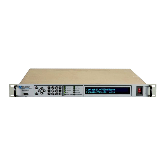
Page 42: Front Panel
SLM-5650A Satellite Modem Revision 10 1.4.2 Front Panel Chapter 7. FRONT PANEL OPERATION Figure 1-4. SLM-5650A Satellite Modem – Front Panel View Table 1-2. Front Panel Item Descriptions Item Name Description USB Port This is currently non-functioning. It is reserved for future software support. -
Page 43: Rear Panel
SLM-5650A Satellite Modem Revision 10 1.4.3 Rear Panel Chapter 4. REAR PANEL CONNECTORS Figure 1-5. SLM-5650A Satellite Modem – Rear Panel View Table 1-3. Rear Panel Item Descriptions Item Name Description AC Power Connector Power interface: 90-264VAC (standard)l 24V DC (optional). - Page 44 SLM-5650A Satellite Modem Revision 10 Notes: Introduction 1–16 MN-SLM-5650A...
-
Page 45: Chapter 2. Specifications
SLM-5650A Satellite Modem Revision 10 Chapter 2. SPECIFICATIONS Summary of Specifications Table 2-1. Summary of Environmental and Physical Specifications Environmental and Physical Specifications Parameter Specifications Prime Power 90 to 264 VAC 47 to 63 Hz 130W (maximuim), 90W (typical) 24VDC optional... -
Page 46: Table 2-2. Summary Of General Specifications
SLM-5650A Satellite Modem Revision 10 Table 2-2. Summary of General Specifications General Specifications Parameter Specifications Operating Frequency Range 52 to 88 104 to 176 950 to 2000 MHz (in 100 Hz steps) Modulation Types BPSK, QPSK, OQPSK, 8PSK, 8QAM, 16QAM Digital Data Rates 64 kbps to 2.5 Mbps, in 1 bps steps (EIA-530, EIA-613) -
Page 47: Table 2-3. Summary Of Modulator Specifications
SLM-5650A Satellite Modem Revision 10 Table 2-3. Summary of Modulator Specifications Modulator Specifications Parameter Specifications Output Power +10 to -40 dBm, adjustable in 0.1 dB steps. In Extended Temperature Range of -32° to 0°C, TX Power accuracy is ∀1.5 dB,... -
Page 48: Table 2-4. Summary Of Demodulator Specifications
SLM-5650A Satellite Modem Revision 10 Table 2-4. Summary of Demodulator Specifications Demodulator Specifications Parameter Specifications Input Carrier Power 70/140MHz: +10 to –55 dBm • L-Band: • +10 to –55 dBm carrier (SR > 3.2 Msps) +10 to [–55 - 10log (3.2/SR)], (SR ≤... -
Page 49: Table 2-6. Summary Of Open Network Options
SLM-5650A Satellite Modem Revision 10 Table 2-6. Summary of Open Network Options Open Network Options Parameter Specifications INTELSAT IESS-308 (Framing only) • INTELSAT IESS-310 (Framing only) • INTELSAT IESS-310 (Framing only) • INTELSAT IESS-309 (Framing only) • Table 2-7. Acquisition and Timing Performance Requirements... -
Page 50: Table 2-8. Doppler Requirements
2-14 when using the modulation formats indicated. Turbo Coding Mode The SLM-5650A operating in the Turbo Code Mode provides back-to-back BER vs. performance better than or equal to the values shown in Table 2-15 when using the modulation formats indicated. -
Page 51: Ber Performance
SLM-5650A Satellite Modem Revision 10 BER Performance 2.2.1 BPSK/QPSK/Offset QPSK, Viterbi Decoding Table 2-10. Viterbi Decoder BER (dB) Specifications Viterbi Decoder Uncoded 10.8 11.6 12.4 13.0 2.2.2 BPSK/QPSK/Offset QPSK, Viterbi Decoding and Reed-Solomon Table 2-11. BSPK/QPSK/OQPSK Viterbi with Reed-Solomon Decoder BER Performance... -
Page 52: 8Psk, Trellis Decoder And Reed-Solomon
SLM-5650A Satellite Modem Revision 10 2.2.4 8PSK, Trellis Decoder and Reed-Solomon Table 2-13. 8PSK, Trellis Decoder with Reed-Solomon BER Performance (dB) Specifications Trellis Decoder with Reed-Solomon 2.2.5 16QAM, Viterbi Decoder and Reed-Solomon Table 2-14. 16QAM, Viterbi Decoder with Reed-Solomon BER Performance... -
Page 53: Sequential Decoding With/Without Reed-Solomon
SLM-5650A Satellite Modem Revision 10 2.2.7 Sequential Decoding with/without Reed-Solomon Table 2-16. Sequential Decoding with / without Reed-Solomon BER Performance (dB) Specifications Sequential Decoder with / without Reed-Solomon BPSK QPSK/OQPSK DESCRIPTION Sequential – 64 kbps Sequential – 1544 kbps Sequential+RS (225,205) 2.2.8... - Page 54 SLM-5650A Satellite Modem Revision 10 Asymmetrical Adjacent Carriers Operating in the presence of two adjacent asymmetrical carriers, one lower in frequency and one higher in frequency, and each adjacent carrier symbol rate (R" ) = 2.0 R' , the modem performance is not degraded more than indicated in Table 2-17 Column 4, and a) and b) in this section.
-
Page 55: Ldpc Ull Decoding
SLM-5650A Satellite Modem Revision 10 2.2.9 LDPC ULL Decoding Table 2-18. LDPC ULL Decoder BER Performance Eb/N0 (dB) Specification BPSK QPSK 2.2.10 LDPC LL Decoding Table 2-19. LDPC LL Decoder BER Performance Eb/N0 (dB) Specification BPSK QPSK 8QAM 16QAM .378 .451... - Page 56 SLM-5650A Satellite Modem Revision 10 BLANK PAGE Specifications 2–12 MN-SLM-5650A...
-
Page 57: Chapter 3. Installation
DAMAGE BY ELECTROSTATIC DISCHARGE (ESD). USE ESD PRECAUTIONARY PROCEDURES WHEN HANDLING THE EQUIPMENT. The SLM-5650A Satellite Modem, its optional Installation and Operation Manual (otherwise available online at http://www.comtechefdata.com), and its power cord were packaged and shipped in a reusable cardboard carton containing protective foam spacing (Figure 3-1). -
Page 58: Inspect The Shipment
User-supplied screws to secure the front panel to the rack enclosure threaded front mounting rails • Comtech EF Data’s optional KT/6228-2 (4”) or KT/6228-3 (10”) Rear Support Brackets Kit (Figure 3-3) • Comtech EF Data’s optional FP/SL0006 26” Bearingless Rack Slide Set (Figure 3-4) For information about custom rack enclosures, contact Comtech EF Data Product Support. -
Page 59: Figure 3-2. Unit Rack Enclosure Installation
SLM-5650A Satellite Modem Revision 10 Feature Description Custom Rack Enclosure SLM-5650A chassis Standard Rack Shelving Rack Enclosure Threaded Front Rail (typical) Unit Front Panel User-supplied Screws Figure 3-2. Unit Rack Enclosure Installation Installation 3–3 MN-SLM-5650A... -
Page 60: Install The Optional Rear Support Brackets Kit
SLM-5650A Satellite Modem Revision 10 3.2.1 Install the Optional Rear Support Brackets Kit Feature Description Back of Unit Rack Enclosure Threaded Rear Mounting Rail (typical) Figure 3-3. Optional Rear Support Brackets Kit Installation Table 3-1. Optional Rear Support Bracket Kit Parts List... - Page 61 SLM-5650A Satellite Modem Revision 10 Do these steps to install the brackets kit (Figure 3-3): Tools needed to install the optional KT/6228-2 (4”) or KT/6228-3 (10”) Brackets Kit: • A medium Phillips screwdriver • A 5/32-inch SAE Allen Wrench ...
-
Page 62: Install The Optional Bearingless Rack Slide Set
Figure 3-4. Optional Bearingless Rack Slide Set Installation You may install the optional FP/SL0006 Bearingless Rack Slide Set into the equipment rack cabinet and onto the sides of the SLM-5650A, as shown in Figure 3-4. Do these steps 1. Use the provided hardware (not shown) to install one slide onto each side of the SLM-5650A chassis. -
Page 63: Connect External Cables
Do these steps: 1. Make to read and become familiar with Chapter 7. FRONT PANEL OPERATION before proceeding. 2. Connect the supplied power cable between your power source and the SLM-5650A rear panel. 3. Set the power switch to ON. - Page 64 SLM-5650A Satellite Modem Revision 10 Notes: Installation 3–8 MN-SLM-5650A...
-
Page 65: Chapter 4. Rear Panel Connectors
CONNECTORS Overview – Cabling Connection Types Comtech EF Data’s SLM-5650A Satellite Modems use a number of different cables. Each cable type is typically dedicated to a specific mode of operation. Not all of these operational interface types may be available. -
Page 66: Coaxial Cable Connections
(BOTTOM) Threaded Coupling Plug and Jack (Type ‘N’ Shown) Figure 4-1. Coaxial Connector Examples The types of coaxial cables used by Comtech EF Data are ‘BNC’, ‘TNC’, ‘N’, ‘F’, and ‘SMA’. Coaxial cables (plugs) and their mating connectors (jacks/sockets) are available in two coupling styles –... -
Page 67: Type 'Bnc
SLM-5650A Satellite Modem Revision 10 4.1.1.1 Type ‘BNC’ BNC plugs and jacks feature a Bayonet Coupling design. 4.1.1.2 Type ‘TNC’ TNC plugs and jacks feature a Threaded Coupling design similar to Type ‘N’, Type ‘F,’ and Type ‘SMA’ connectors. 4.1.1.3 Type ‘N’... -
Page 68: D-Subminiature Cable Connections
SLM-5650A Satellite Modem Revision 10 4.1.2 D-Subminiature Cable Connections Type ‘D’ Cable with Jack Screws Type ‘D’ Chassis Receptacles (Female Shown) with Jack Nuts: (TOP) Female (BOTTOM) Male Figure 4-2. D-Subminiature Connector Examples D-Subminiature connectors are also called Type ‘D’ or ‘D-Sub’ connectors. The cable plug and chassis receptacle each feature a D-shaped profile that interlock to ensure proper pin orientation and connector seating. -
Page 69: Usb Cable Connections
SLM-5650A Satellite Modem Revision 10 4.1.4 USB Cable Connections (TOP) Type ‘A’ USB Plug and Receptacle (BOTTOM) Type ‘B’ USB Plug and Receptacle Figure 4-4. USB Connector Examples A Universal Serial Bus (USB) connection is used as a bus-type communications or power interface between peripheral devices. -
Page 70: Unit Connectors
SLM-5650A Satellite Modem Revision 10 Unit Connectors Figure 4-5. SLM-5650A Rear Panel View External cables are attached to connectors provided on the rear panel of the unit (Figure 4-5). These connectors serve power and ground, modem utility, terrestrial data interface, and IF functions. - Page 71 SLM-5650A Satellite Modem Revision 10 Item Name Description ‘J6 EIA530’ (DB-25F) This Type ‘D’ 25-pin female (DB-25F) connector conforms to the EIA-530 pinout Data Interface for EIA-422 operation only. Connector Pin # Signal Function CS_B NOT USED ST_B TT_A TT_B...
- Page 72 SLM-5650A Satellite Modem Revision 10 Item Name Description ‘P1 Overhead Data’ This Type ‘D’ 25-pin male (DB-25M) connector allows for connection of the (DB-25M) Interface EIA-422, EIA-485 and EIA-232 data interfaces used with overhead framing. It also supports signaling for tactical applications.
- Page 73 SLM-5650A Satellite Modem Revision 10 Item Name Description ‘J7 HSSI’ Interface This is a 50-pin SCSI-2 female connector. Pins 21 and 45 are non-HSSI defined signals. On Cisco routers, there is no connection to these pins. Fault Open No Fault Ground...
- Page 74 SLM-5650A Satellite Modem Revision 10 Ground (cont) Ground Not Used Not Used Ground Ground ‘J8 Alarms’ (DB-9F) This Type ‘D’ 9-pin female (DB-9F) connector provides Form ‘C’ contact closures Utility Connector for alarm reporting. The three Form ‘C’ summary fault contacts are Modulator, Demodulator, and Common Equipment.
- Page 75 SLM-5650A Satellite Modem Revision 10 Item Name Description ‘J9 Auxiliary’ (HD- This Type ‘HD’ 15-pin female (HD-15F) connector is used for redundancy switch 15F) Utility Connector operations. It provides TTL (Transistor-to-Transistor Logic) open collector faults for the modulator and demodulator; a TTL input for external transmit carrier mute;...
- Page 76 SLM-5650A Satellite Modem Revision 10 Item Name Description Data Interface Module Appendix D. OPTIONAL DATA INTERFACE MODULES Slot (includes the optional 10/100/1000 BaseT Gigabit Ethernet (GbE), G.703, and LVDS modules) Appendix E. OPTIONAL NETWORK PROCESSOR (NP) INTERFACE MODULE Install optional data interface modules into this rear panel option slot.
-
Page 77: Ac Operation - Replace The Fuses
SLM-5650A Satellite Modem Revision 10 4.2.1.1.1 AC Operation – Replace the Fuses DISCONNECT THE POWER SUPPLY BEFORE PROCEEDING! FOR CONTINUED OPERATOR SAFETY, ALWAYS REPLACE THE FUSES WITH THE CORRECT TYPE AND RATING. Figure 4-6. AC Fuse Replacement Do these steps to replace the AC fuses (Figure 4-6): 1. -
Page 78: Ac Operation - Apply Power
SLM-5650A Satellite Modem Revision 10 4.2.1.1.2 AC Operation – Apply Power Figure 4-7. AC Power to the Unit Do these steps to apply AC power to the unit (Figure 4-7): 1. Plug the provided AC power cord female end into the unit. -
Page 79: Power Interface Module - Optional 24V Dc Unit
Revision 10 4.2.1.2 Power Interface Module – Optional 24V DC Unit Contact Comtech EF Data Product Support for detailed information about connecting and supplying power, and replacing the fuses for the optional DC-powered SLM-5650A. 4.2.1.2.1 DC Operation – Replace the Fuses... - Page 80 SLM-5650A Satellite Modem Revision 10 Notes: Rear Panel Connectors 4–16 MN-SLM-5650A...
-
Page 81: Chapter 5. Firmware Update
If you need to update the firmware, you can apply the update to the modem without having to remove it from operation. You may directly acquire the download from Comtech EF Data’s web site or receive the archive file by e-mail from Comtech EF Data Product Support. -
Page 82: About Firmware Numbers, File Versions, And Formats
The SLM-5650A files are provided under “Home | Support | Software Downloads | Flash & Software Update Files |Satellite Modems | SLM-5650A”. Typical for all names, ‘X’ is the revision letter, and ‘###’ represents the firmware version number – e.g., V148 = Version 1.4.8: •... -
Page 83: Prepare For The Firmware Download
SLM-5650A Satellite Modem Revision 10 Prepare for the Firmware Download 5.2.1 Required User-supplied Items You will need: • A Microsoft Windows-based PC, equipped with available serial and Ethernet ports. • A 9-pin serial cable and an RJ-45 CAT5 Ethernet cable to connect the User PC to the modem. -
Page 84: Configure The Terminal Emulator Program
SLM-5650A Satellite Modem Revision 10 5.2.2 Configure the Terminal Emulator Program On the User PC – Open the terminal emulator program, and then configure the program’s serial port communication and terminal display operation: • Baud Rate = 38400 bps •... -
Page 85: Use Front Panel Operation To Find The Management Ip Address
SLM-5650A Satellite Modem Revision 10 5.2.3.1 Use Front Panel Operation to Find the Management IP Address Ethernet IP Address/Range: 192.168.001.001/24 (E) You may view the assigned Management IP Address on the SELECT: Configure Remote EthernetConfig IP Address/Range screen. -
Page 86: Use The Base Modem Http Interface To Find The Firmware Information
The ‘Firmware Information’ section of the ‘Maint | Unit Info’ page provides the Firmware Information details as Boot, Bulk1, and Bulk2 as shown in this example: Write down your firmware information for further reference or to provide to Comtech EF Data Product support. -
Page 87: Use Windows Desktop To Make A Folder
SLM-5650A Satellite Modem Revision 10 5.2.4.1 Use Windows Desktop to Make a Folder Do these steps: Step Task Right-click anywhere on the desktop to open the popup submenu. Select New > Folder to make the new, temporary folder on the desktop. -
Page 88: Use Windows Explorer To Make A Folder
SLM-5650A Satellite Modem Revision 10 5.2.4.2 Use Windows Explorer to Make a Folder Do these steps: Step Task Left-double-click the Windows Explorer icon on the Windows Desktop. Depending in your Windows OS version: select File > New > Folder, or click your Folder Destination (e.g., Windows (C:) and then New Folder to make the new, temporary folder in the... -
Page 89: Use The Run And Browse Windows To Make A Folder
SLM-5650A Satellite Modem Revision 10 5.2.4.3 Use the Run and Browse Windows to Make a Folder Select Start on the Windows taskbar and then do these steps: Step Task Click Run… to open the Run window. Click Browse… to open the Browse window. -
Page 90: Use Windows Command-Line Or Command Prompt To Make A Folder
SLM-5650A Satellite Modem Revision 10 5.2.4.4 Use Windows Command-line or Command Prompt to Make a Folder Select Start on the Windows taskbar and then do these steps: Step Task Click Run... to open the Run window (or, depending on Windows OS version prior to Windows 95,... -
Page 91: Download And Extract The Firmware Update Files
On the Flash Updates Index page – Select the (Select a Product Line) Satellite Modems hyperlink. On the Modems product page – Select the SLM-5650A product hyperlink. Select the appropriate firmware archive EXE or ZIP file download hyperlink. Once you select the EXE or ZIP hyperlink, the File Download dialogue opens on your browser and prompts an action. - Page 92 SLM-5650A Satellite Modem Revision 10 Click [Save] to download the EXE file to your Downloads folder. Once the download is complete the dialogue prompts you to either [Run] the self-extracting file, or to open or view the Windows Downloads folder for further action.
-
Page 93: Use Windows Desktop To View Folder Contents
SLM-5650A Satellite Modem Revision 10 5.2.5.1 Use Windows Desktop to View Folder Contents From the Windows Desktop: Step Task Double-left-click the Windows Explorer icon, and then double-left-click as needed to locate, and then open, the “temp” folder (directory) created earlier on the Windows Desktop. -
Page 94: Upload The Bulk Firmware Files And Update The Modem
SLM-5650A Satellite Modem Revision 10 Upload the Bulk Firmware Files and Update the Modem 5.3.1 Important Considerations Before you proceed with the firmware update, make sure that: • You connect the modem ‘J5 Ethernet’ M&C port to the User PC as described in Section 5.2.1.1. - Page 95 SLM-5650A Satellite Modem Revision 10 The process sequences through several blocks – this may take several minutes for the transfer to occur. The modem front panel reports the status as follows: Programming flash sector #xx Please wait… If you stop the transfer before the “PROGRAMMING FLASH SECTOR#xx PLEASE WAIT”...
-
Page 96: Optional Network Processor (Np) Module Interface Firmware Update Procedure
SLM-5650A Satellite Modem Revision 10 Optional Network Processor (NP) Module Interface Firmware Update Procedure Appendix E. OPTIONAL NETWORK PROCESSOR (NP) INTERFACE MODULE Do these steps: Step Task Find the current firmware information via the front panel, or the HTTP or Serial interface (see Sections 5.2.3.2, 5.2.3.3, or 5.2.3.4). - Page 97 SLM-5650A Satellite Modem Revision 10 Depending on the NP Module’s security level setting: Type “http://xxx.xxx.xxx.xxx” for non-secure access (Low Security Mode); • Type “https:/xxx.xxx.xxx.xxx” for SSH (Secure Shell) access (High Security Mode). When • prompted, enter the User Name and Password to log in: Factory Default User Name is comtech;...
- Page 98 SLM-5650A Satellite Modem Revision 10 During the upload process, the page displays a transfer progress bar that provides the scrolling percentage of completion. During transfer, the message Please Wait… displays: Upon successful completion of transfer, the progress bar reads 100%, and the Image Upgrade Complete message displays: Click [OK] to exit the Image Upgrade page and return to the Admin | Upgrade page.
- Page 99 SLM-5650A Satellite Modem Revision 10 After saving, return to the Admin | Reboot page, then click [Reboot Now] to boot the NP Module with the new firmware: To load the second image, repeat Steps 8 through 10. Firmware Update 5–19...
-
Page 100: Optional Transec Module Interface Firmware Update Procedure
Firmware updates for the TRANSEC Module (also referred to in front panel menu screens as the “Option Card”) are not available from the Comtech EF Data Web site, but they may be obtained from Comtech EF Data on an as-needed basis. To obtain these updates, contact Comtech EF Data Product Support to request access to the modem firmware update files online FTP site. - Page 101 SLM-5650A Satellite Modem Revision 10 To log in to the secure interface, select Crypto Officer from the navigation list that is provided in the upper left-hand corner of each page, then click [Go!]. When prompted, enter the User Name and Password at the Login page: Factory Default User Name is comtech •...
- Page 102 SLM-5650A Satellite Modem Revision 10 Any power failure during this process will result in failure of the TRANSEC Module. In the event that an error occurs during the Firmware Application Process, the following message is displayed: For troubleshooting purposes, three common reasons for disruption of the Firmware Application Process are: Power Failure;...
- Page 103 SLM-5650A Satellite Modem Revision 10 Click [Reboot Now!] to boot the TRANSEC Module with the new firmware: The modem will reboot with the new firmware loaded as configured: Restart the TRANSEC Module HTTPS Interface browser session once the modem returns online.
-
Page 104: Usb Firmware Update Procedure
Revision 10 USB Firmware Update Procedure Use of the front panel USB port for the firmware update process is not available in this firmware release. Please contact Comtech EF Data Product Support for this feature’s release schedule. Firmware Update 5–24... -
Page 105: Chapter 6. Fast Activation Procedure
If you wish to upgrade the functionality of a unit at a later date, Comtech EF Data provides Fully Accessible System Topology (FAST), which permits the purchase and activation of options through special authorization codes. -
Page 106: Fast Activation Procedure Via The Slm-5650A Front Panel
Chapter 7. FRONT PANEL OPERATION for complete information about using this interface. Do these steps: 1. Before contacting Comtech EF Data Product Support to order FAST feature upgrades, obtain and record the modem’s motherboard serial number: a. From the front panel main SELECT: menu, select Utility►FAST, and then press [ENT]. -
Page 107: Chapter 7. Front Panel Operation
Figure 7-1. SLM-5650A Satellite Modem – Front Panel View The front panel USB 1.1 port is non-functional. The SLM-5650A Satellite Modem allows you to locally monitor the modem operating status (including clocking information) and to control modem configuration parameters. The front panel (Figure 7-1) provides these operational features: •... -
Page 108: Keypad With Data Entry Array
SLM-5650A Satellite Modem Revision 10 7.1.1 Keypad with Data Entry Array The front panel keypad (Figure 7-1, items 2 and 3) controls the local operation of the modem. Enter data via the keypad. Data, prompts, and messages appear on the VFD. -
Page 109: Led Indicators
SLM-5650A Satellite Modem Revision 10 The first three columns of keys are multi-function in purpose. Number-to-character assignment for this array means that each successive push of key 1 through 9 selects the nested choices. For example, the first time the ‘2’ key is pushed, it selects a ‘2’; the second time, an ’A’; the third time, a ‘B’;... -
Page 110: Vacuum Fluorescent Display (Vfd)
7.1.3 Vacuum Fluorescent Display (VFD) The SLM-5650A features a VFD (Item 5 in Figure 7-1). The VFD is an active display showing two lines of 40 characters each. It produces a blue light with adjustavle brightness. Compared to a LCD, it has superior viewing characteristics and does not suffer problems of viewing angle or contrast. - Page 111 15 minutes. This message constantly scrolls and wraps across the screen. Sandwiched between the product display message “Comtech EF Data SLM-5650A Modem” and the user prompt “Press any key to continue”, the screen saver provides the following...
-
Page 112: Navigating The Menu Screens
SLM-5650A Satellite Modem Revision 10 7.1.3.1 Navigating the Menu Screens Both single-function and multi-function menu screens are used throughout the front panel SELECT: menu interface. Both screen types display all available options and prompt the user to carry out a required action. -
Page 113: Front Panel Operation
The front panel menu screens provide the visual means to fully control and monitor operation of the SLM-5650A. The first screen to display, after the modem power switch is turned ON (Item 1 in Figure 7-1), is the read-only opening screen:... -
Page 114: Select:) Configure (Configuration) Menu Branch
“Modem Type” has been set to AUPC. TRANSEC 7.2.3.5 Use to configure the optional TRANSEC (Transmission Security) Module features. Use to configure the Antenna Handover features (when the SLM-5650A is used AntHndOvr 7.2.3.6 with the CRS-311-AH Antenna Handover Switch). This menu is selectable only if the Antenna Handover FAST option is installed. -
Page 115: Config:) Tx
SLM-5650A Satellite Modem Revision 10 7.2.3.1 (CONFIG:) Tx Tx: Mod DataRate Overhead Frequency Power Clocking Misc Spreading (E) Use the arrow keys to select a Tx configuration submenu. Press [ENT]: Submenu Option Select: FEC; Type; Rate; RS; Diff; Scrambler. - Page 116 Differential Encoder: On or Off Scram Scrambling (for energy dispersal): V.35 – ITU standard. • MOD-V.35 (Modified V.35) – Comtech EF Data Closed Network with Reed- Solomon • compatible . IBS – Used for IESS-309 operation. • Turbo – Synchronous scrambler synchronized to the Turbo block.
- Page 117 SLM-5650A Satellite Modem Revision 10 (CONFIG:) Tx DataRate Tx Data Rate: 020000.000 kbps Sym Rate: 0266666.666 ksps(E) Use Method 1 or Method 2 to enter the desired Tx Data Rate (in kilobits per second): Method Procedure Use the number keypad and enter the desired data rate. Press [ENT].
- Page 118 SLM-5650A Satellite Modem Revision 10 (CONFIG:) Tx Frequency Tx Frequency: 1955.0000 MHz Spectrum: Normal (E) Use the arrow keys to select Tx Frequency or Spectrum. Press [ENT]. Use Method 1 or Method 2 to enter the desired Tx Frequency:...
- Page 119 SLM-5650A Satellite Modem Revision 10 (CONFIG:) Tx Clocking Tx Clocking: CLK Source: SCT (E) SCT Ref: Reference Use the arrow keys to select Clk Source or SCT Ref. Press [ENT]. Option Setting Clk Source Use the arrow keys to select SCT or Tx-Terr. Press [ENT].
- Page 120 SLM-5650A Satellite Modem Revision 10 (CONFIG:) Tx Spreading Tx Spreading: Factor:001 Equation:1 Chip Rate: 000128.000 kcps (E) Use the arrow keys to select Factor or Equation. Press [ENT]. Option Setting Factor Tx Spreading Factor (1-512), where 1=Spreading OFF.
-
Page 121: Config:) Rx
SLM-5650A Satellite Modem Revision 10 7.2.3.2 (CONFIG:) Rx Rx: Demod DataRate Overhead Frequency Acq Buffer Misc CnC Spreading (E) Use the arrow keys to select an Rx configuration submenu. Press [ENT]: Submenu Option Demod Select FEC, Type, Rate, RS, Diff, or Descrambler. - Page 122 Differential Decoder: On or Off. Descram Descrambling: V.35 – ITU standard; • MOD-V.35 (modified V.35) – Comtech EF Data Closed Network with Reed-Solomon • compatible; IBS – Used for IESS-309 operation; • Turbo – Synchronous descrambler synchronized to the Turbo block;...
- Page 123 SLM-5650A Satellite Modem Revision 10 (CONFIG:) Rx DataRate Rx Data Rate: 020000.000 kbps Sym Rate: 0266666.666 ksps(E) Use Method 1 or Method 2 to enter the desired Rx Data Rate (in kilobits per second): Method Procedure Use the number keypad and enter the desired data rate (see Appendix B. OPERATIONAL REFERENCES).
- Page 124 SLM-5650A Satellite Modem Revision 10 (CONFIG:) Rx Frequency Rx Frequency: 1955.0000 MHz Spectrum: Normal (E) Use the arrow keys to select Rx Frequency or Spectrum. Press [ENT]. Use Method 1 or Method 2 to enter the desired Rx Frequency:...
- Page 125 SLM-5650A Satellite Modem Revision 10 (CONFIG:) Rx Buffer Buffer: Src:RX-Sat Center: Y/N ExtClk Size:00001024 Mode:Bits Framing (E) Use the arrow keys to select Src, Center, ExtClk, Size, Mode, or Framing. Press [ENT]. Use the arrow keys to scroll through the available settings. Select your setting. Press [ENT] to finish.
- Page 126 SLM-5650A Satellite Modem Revision 10 (CONFIG:) Rx Misc Rx Misc: Clk/DataPhase BitOrdering Eb/No Threshold (E) Use the arrow keys to select Clk/DataPhase, BitOrdering, or Eb/No Threshold. Press [ENT]. (CONFIG:) Rx Misc Clk/DataPhase Rx Clock Phase: Normal Data Phase: Normal (E)
- Page 127 SLM-5650A Satellite Modem Revision 10 (CONFIG:) Rx CnC Acquisition CnC Acquisition: Range: 60.000 KHz Reacq: 120 Sec (E) Use the arrow keys to select Range or Reacq. Press [ENT]. Option Settings Range CnC Interfering Carrier Frequency Offset Search Range: 0-60 kHz (in 1 Hz steps).
- Page 128 SLM-5650A Satellite Modem Revision 10 (CONFIG:) Rx Spreading Rx Spreading: Factor:001 Equation:1 Chip Rate: 000128.000 kcps (E) Use the arrow keys to select Factor or Equation. Press [ENT]. Option Settings Factor Rx Spreading Factor (1-512), where 1=Spreading OFF.
-
Page 129: Config:) Mode
• IESS-310 – Select functionality defined by IESS-310, the Intelsat 8-PSK Intermediate Data Rate • standard. TURBO – Select functionality defined by IESS-315 plus Comtech EF Data Turbo mode • interoperability. 16QAM – Select 16-QAM as a modulation type. •... - Page 130 SLM-5650A Satellite Modem Revision 10 Option Settings Vipersat mode should not be selected from the front panel under most circumstances. Refer to the supplementary Vipersat User Guide (CEFD P/N MN-0000035) for detailed information on configuring the Vipersat features. When selecting an IF frequency band, both transmit and receive operate in the selected band.
-
Page 131: Config:) Aupc
SLM-5650A Satellite Modem Revision 10 7.2.3.4 (CONFIG:) AUPC You must first go to the (CONFIG:) MODE submenu and set the modem type as AUPC in order to select this menu. AUPC: Local Remote ASYNC Logging (E) Use the arrow keys to select Local, Remote, ASYNC, or Logging. Press [ENT]. - Page 132 View or modify the status of the remote modem’s Tx pattern substitution. Tx Pattern Note: In order to maintain compatibility with older Comtech EF Data modems, only 2047 pattern substitution is supported. Monitor BER of the remote modem. The remote modem must have Tx Pattern set to On and the local modem must be transmitting a 2047 pattern.
- Page 133 SLM-5650A Satellite Modem Revision 10 (CONFIG:) AUPC ASYNC ASYNC: TxBaud:1200 TxFormat:7E2 (E) Type:232 RxBaud:1200 RxFormat:7E2 Use thearrow keys to select TxBaud, TxFormat, Type, RxBaud, or RxFormat. Press [ENT]. Typical for each option, use the arrow keys to scroll through the available settings.
-
Page 134: Config:) Transec
SLM-5650A Satellite Modem Revision 10 7.2.3.5 (CONFIG:) Transec TRANSEC: State: Encrypted Module IP Address Gateway (E) Use the arrow keys to select State, Module IP Address, or Gateway. Press [ENT]. Option Settings State Select Encrypted or Bypass. Module IP Address Set the TRANSEC Module’s Management IP Address and subnet mask length. -
Page 135: Config:) Mask
SLM-5650A Satellite Modem Revision 10 7.2.3.8 (CONFIG:) Mask Mask: TxData RxData Eb/No Threshold DemodFaults (E) Use the arrow keys to select TxData, RxData, Eb/No Threshold, or DemodFaults. Press [ENT]. Option Settings This alarm monitors data activity on the transmit data interface: TxData Use the arrow keys to select Masked, Activity, or AIS. -
Page 136: 7.2.3.10 (Config:) Remote
If you select RS-485, the display will show address 0001 to 9999. This address can be changed using the front panel. The most significant digit is for Comtech EF Data redundancy switches. If you select TTL (Switch), this enables interoperation with the CRS-311 (1:1) or CRS-300 (1:N) redundancy switches. - Page 137 SLM-5650A Satellite Modem Revision 10 (CONFIG:) Remote SerialConfig Format Local M&C Bus Format: (E) Use the arrow keys to select the character format 7N1, 7E1, 7O1, 7N2, 7E2, 7O2, 8N1 (default), 8E1, 8O1, 8N2, 8E2, or 8O2. Press [ENT].
-
Page 138: Config:) Remote Ethernetconfig Snmp
SLM-5650A Satellite Modem Revision 10 (CONFIG:) Remote EthernetConfig Gateway Ethernet Default Gateway IP Address: 192.168.001.001 () The IP Gateway Address is the default address that the modem will send all IP responses when the message originated from a source outside the modems local attached network. To enter the Gateway IP Address, use the arrow keys to select a digit, and then the arrow keys to... - Page 139 SLM-5650A Satellite Modem Revision 10 (CONFIG:) Remote EthernetConfig SNMP Communities Read SNMP Read Community: public (E) To edit the SNMP Read Community string: Use thearrow keys to select a character, and then use the arrow keys to change that character.
- Page 140 SLM-5650A Satellite Modem Revision 10 (CONFIG:) Remote EthernetConfig SNMP Traps Address #1/#2 SNMP Traps IP Address #X: 000.000.000.000 (E) Where X indicates IP Address #1 or IP Address #2: To edit the SNMP Trap Destination IP Address: Use the arrow keys to select a digit, and then use the ...
-
Page 141: Config:) Remote Ethernetconfig Option Card Addr
SLM-5650A Satellite Modem Revision 10 (CONFIG:) Remote EthernetConfig SNMP Traps Version SNMP Trap Version: SNMPv1 SNMPv2 SNMPv3 (E) Use the arrow keys to select SNMPv1, SNMPv2, or SNMPv3. Press [ENT]. The Trap Version selection is forced to SNMPv3 if you select SNMPv3 as your SNMP Version. - Page 142 SLM-5650A Satellite Modem Revision 10 (CONFIG:) Remote EthernetConfig Option Card Addr Network Proc AddrMode Use the arrow keys to select the Address Mode as Local or Dual. Press [ENT]. • When in Single Address Mode: Select Traffic IP to edit the NP Module Ethernet IP Address and Range •...
-
Page 143: Monitor:) Alarms
SLM-5650A Satellite Modem Revision 10 7.2.4 (SELECT:) Monitor Menu Branch Monitor: Alarms Event-Log Rx-Params Stats GigaBit I/F Stats The Monitor Menu Branch provides submenus that permit you to monitor the alarm status of the unit, to view the log of stored events, and to display the Rx Parameters screen. Use the ... - Page 144 SLM-5650A Satellite Modem Revision 10 (Monitor:) Alarms Receive Demod: ------ Press <ENT> for Intf: ---------- detailed status Press [ENT] to access the available read-only Demodulator and Intf (Interface) Rx alarm screens. Use the arrow keys to navigate through the displayed Demodulator and Interface character positions (Demod#1 through #6, and Rx Intf#1 through #10).
- Page 145 ------- detailed status Press [ENT] to access the available read-only SLM-5650A Unit Alarm screens. Use the arrow keys to navigate through the displayed character positions (Unit#1 through #23). The status message to the right changes based on the current cursor position, as...
-
Page 146: Monitor:) Event-Log
SLM-5650A Satellite Modem Revision 10 7.2.4.2 (Monitor:) Event-Log Stored Events: View Clear-All ModemParameters (E) Use the arrow keys to select View, Clear-All, or ModemParameters. Press [ENT]. (Monitor:) Event-Log View Event 001:003 1:43:02 27/09/05 Mod: ---- ++ -- (E) To view the details of a stored fault: Use the ... -
Page 147: Monitor:) Rx-Params
SLM-5650A Satellite Modem Revision 10 7.2.4.3 (Monitor:) Rx-Params Fc=+05917 RSL<-60.0 dBm BERT=N/A Buf=000% Eb/No=Loss BER <1.0E-12 (E) This read-only screen monitors the following Rx operating parameters: • Fc displays the received carrier frequency offset in Hz. The range is the same as the acquisition range of the modem (60 kHz). -
Page 148: Monitor: Stats (Statistics)
SLM-5650A Satellite Modem Revision 10 7.2.4.5 Monitor: Stats (Statistics) Link Statistics: View Clear-All Config (E) Use the arrow keys to select View, Clear-All, or Config. Press [ENT]. Monitor: Stats View Event 001:003 1:43:02 27/09/11 Min: Loss Avg: Loss (E) -
Page 149: Select:) Test Menu Branch
SLM-5650A Satellite Modem Revision 10 7.2.5 (SELECT:) Test Menu Branch TEST: Carrier Loopback BERT LampTest (E) Select the Carrier, Loopback, BERT, or LampTest submenu. Press [ENT]. Carrier Test Modes, Loopback, and Tx BERT are not allowed when the modem is set to Demod Only. -
Page 150: Test:) Bert
SLM-5650A Satellite Modem Revision 10 7.2.5.3 (TEST:) BERT BERT: Tx:Off Pattern:2047 ErrIns Reset Rx:Off Errs:=0000000 BER:NoSync Use the arrow keys to select Tx, Pattern, ErrIns, Reset, Rx, Errs, or BER. Press [ENT]. For any option, use the arrow keys to select the desired setting. Press [ENT] to execute the test. -
Page 151: Select:) Save/Load Menu Branch
SLM-5650A Satellite Modem Revision 10 7.2.6 (SELECT:) Save/Load Menu Branch Save/Load: Loc:0 Action: View Empty (E) Use the arrow keys to select Loc or Action. Press [ENT]. Option Settings There are 10 locations available [0-9]. To save or load a stored configuration, use the ... -
Page 152: Select:) Utility Menu Branch
SLM-5650A Satellite Modem Revision 10 7.2.7 (SELECT:) Utility Menu Branch UTIL: RT-Clk RefAdjust ID Display Temp Agc Alarm PwrCal Firmware FAST (E) Use the arrow keys to select RT-Clk, RefAdjust, ID, Display, Temp, Agc, Alarm, Alarm, PwrCal, Firmware, or FAST submenu. Press [ENT]. -
Page 153: Util:) Agc (Automatic Gain Control)
SLM-5650A Satellite Modem Revision 10 7.2.7.6 (UTIL:) Agc (Automatic Gain Control) AgcMon: Min Value: 00.0 Volts Max Value: 10.0 Volts (E) Use this submenu to set the minimum and maximum voltage levels for the external AGC monitor voltage that is available through the rear panel ‘J9 Auxiliary’ connector. - Page 154 SLM-5650A Satellite Modem Revision 10 (UTIL:) Firmware Information Bootrom Bootrom: 10/18/07 FW-0000029- 1.1.1 This screen displays the Bootrom release date, the Firmware number and the revision number. Press [ENT] or [CLR] to return to the previous menu. (UTIL:) Firmware Information Image#X Image#X: Bulk App M&C Mod Demod Decoder...
-
Page 155: 7.2.7.10 (Util:) Fast
SLM-5650A Satellite Modem Revision 10 7.2.7.10 (UTIL:) FAST Chapter 6. FAST ACTIVATION PROCEDURE FAST: Configuration S/N 000000000 View Options (E) Use the arrow keys to select View Options or Configuration. Press [ENT]. (UTIL:) FAST View Options View Options: 01 Installed Data Rate <= 155 Mbps... -
Page 156: Enter Modem Code (Fast Activation Procedure)
Enter Modem Code (FAST Activation Procedure) Chapter 6. FAST ACTIVATION PROCEDURE for the proper use of Enter Modem Code. This is a 20-digit code, purchased from Comtech EF Data product Support, which permits upgrading the modem functionality. Legal characters are hexadecimal, 0-F. -
Page 157: Fast Demo Mode
FAST Demo Mode: Off (Off,On) 604800 seconds remain (E) FAST Demo Mode allows access to ALL SLM-5650A FAST Options for 604800 seconds (seven 24-hour calendar days). The bottom line displays the time remaining – the time format is in seconds. - Page 158 SLM-5650A Satellite Modem Revision 10 BLANK PAGE Front Panel Operation 7–52 MN-SLM-5650A...
-
Page 159: Chapter 8. Ethernet Interface Operation
3 and 4. The operational mode of these ports can be individually selected for Auto-Negotiation or fixed mode operation. The internal systems of the SLM-5650A are interconnected with an internal Ethernet bus, which allows both the Base Modem ‘J5 Ethernet’ port and NP Ports 1 through 4 to provide M&C access while the NP is operating in Router modes. -
Page 160: Secure Ethernet Management Interfaces
Simple Network Management Protocol (SNMP) - This protocol requires a user- supplied Network Management System (NMS) or a user-supplied MIB File Browser. Comtech EF Data supplies the MIB File sets required for the SLM-5650A Modem. SNMP is NOT supported by the TRANSEC module. -
Page 161: Optional Np Interface Module
SLM-5650A Satellite Modem Revision 10 8.1.1.2 Optional NP Interface Module When the optional NP Interface is installed in the SLM-5650A, the NP Management Security (available as a FAST Option) may be used to change to an alternative secure network management mode: •... -
Page 162: Base Modem + Optional Np Interface + Optional Transec Module
User name and Password for login. See Figure 8-1. The TRANSEC Module is always accessible through the Base Modem ‘J5 Ethernet’ port. When the optional NP Interface is installed in the SLM-5650A in tandem with the optional TRANSEC Module Interface, and Management Security is enabled, the network management operating restrictions as previously described (i.e., when High Level Security is selected) - Page 163 SLM-5650A Satellite Modem Revision 10 The TRANSEC Module Interface provides a proxy function of HTTPS connections to the Base Modem and the NP Interface; a secure HTTPS connection to the TRANSEC Module therefore enables user access to all Base Modem and/or all NP M&C parameters securely through this indirect proxy connection.
-
Page 164: Snmp Interface
• The managed device. This includes the SLM-5650A Satellite Modem. • The SNMP Agent. The software that runs on the SLM-5650A. The SLM-5650A SNMP Agent supports SNMPv1, SNMPv2c, and SNMPv3. • The user-supplied NMS. The software that runs on the manager. -
Page 165: Snmp Community Strings
20. All printable ASCII characters, except ’\’ and ‘~’ are allowed. No trailing spaces for community strings. For proper SNMP operation, the SLM-5650A MIB files must be used with the associated version of the SLM-5650A base modem M&C. Please refer to the SLM-5650A SW Release Notes for information on the required FW/SW compatibility. -
Page 166: Snmpv3 (Base Modem)
SLM-5650A Satellite Modem Revision 10 The modem supports the following Alarms and Faults SNMPv1 traps / SNMPv2 notifications: Alarms and Faults SNMPv1 Traps slm5650TxTrafficAlarmV1 6247472 slm5650UnitAlarmV1 6247471 slm5650RedundancyStateV1 6247473 slm5650RedundancyStateV1 6247474 Alarms and Faults SNMPv2 Notification slm5650UnitAlarmV2 1.3.6.1.4.1.6247.47.2.1.1 slm5650TxTrafficAlarmV2 1.3.6.1.4.1.6247.47.2.1.2 slm5650RxTrafficAlarmV2 1.3.6.1.4.1.6247.47.2.1.3... - Page 167 2. The User Name and Password defined here are the ones used in an SNMP client, and are separate from the user name/password used to access the SLM-5650A HTTP/HTTPS/Telnet interfaces. 3. It is not necessary to change the Engine ID to have an acceptable level of encryption.
-
Page 168: Telnet Interface
Chapter 10. SERIAL INTERFACE OPERATION Figure 8-2. Telnet Interface Example – Windows Command-line The SLM-5650A has a Telnet interface for the purpose of equipment M&C via the Serial Remote Control protocol. The Telnet interface requires user login at the Administrator and Read/Write user access levels. -
Page 169: Configure Hyperterminal For Telnet Remote Control Operation
SLM-5650A Satellite Modem Revision 10 Figure 8-3. Telnet Interface Example – HyperTerminal 8.3.1.1 Configure HyperTerminal for Telnet Remote Control Operation Figure 8-4. Configure HyperTerminal Ethernet Interface Operation 8–11 MN-SLM-5650A... - Page 170 1. Make sure to define the Connect To Telnet connection properties correctly (File Properties) (Figure 8-4, left): a. Enter the SLM-5650A’s Traffic/Management IP Address as the “Host address” (e.g., 192.168.1.1). b. Enter TCP Port 23 as the “Port number”.
-
Page 171: Secure Shell (Ssh) Interface
SLM-5650A Satellite Modem Revision 10 Secure Shell (SSH) Interface Appendix E. OPTIONAL NETWORK PROCESSOR (NP) INTERFACE MODULE, Sect. E.3 Network Processor (NP) Telnet/CLI Interface Operation Appendix F. OPTIONAL TRANSEC MODULE OPERATION, Sect. F.3 SSH CLI OPERATION When the modem is equipped with the optional NP or TRANSEC Module Interfaces, the security and encryption features for either require that administrative maintenance and control operations are accomplished using a SSH CLI. -
Page 172: Figure 8-6. Cli Session Examples
SLM-5650A Satellite Modem Revision 10 To initiate a SSH CLI session, do these steps: 1. From the SSH terminal emulation program’s folder, double-click the program filename (e.g., putty.exe), shortcut, icon, etc. to open the SSH application and its configuration window. -
Page 173: Chapter 9. Base Modem Http Interface Operation
Revision 10 Chapter 9. BASE MODEM HTTP INTERFACE OPERATION Overview The operational parameters available from the SLM-5650A Base Modem’s non-secure HTTP (Web Server) Interface complement operation of the SLM-5650A’s front panel menus. 9.1.1 Prerequisites Before you proceed with non-secure Ethernet remote product management, make sure the following is true: •... -
Page 174: Base Modem Http Interface
Revision 10 Base Modem HTTP Interface A user-supplied web browser allows the full monitoring and control (M&C) of the SLM-5650A base modem from its HTTP Interface. This non-secure embedded web application is designed for, and works best with, Microsoft Internet Explorer Version 7.0 or higher, Firefox, and Google Chrome. - Page 175 SLM-5650A Satellite Modem Revision 10 Once the valid User Name and Password is accepted, the HTTP Interface splash page appears (Figure 9-1). The firmware version as shown here may differ from your setup. Figure 9-1. HTTP Interface Page Example Base Modem HTTP Interface Operation 9–3...
-
Page 176: Http Interface Features
SLM-5650A Satellite Modem Revision 10 9.2.3 HTTP Interface Features 9.2.3.1 Page Navigation The HTTP Interface has five navigation tabs at the top of each page. Click a navigation tab to see its page hyperlinks. Click a page hyperlink to open a page. -
Page 177: Action Buttons
SLM-5650A Satellite Modem Revision 10 9.2.3.3 Action Buttons Action buttons are important in the HTTP Interface. Click an action button to do one of these tasks: • Click [Refresh] to see the latest page data. • Reset changed parameters to remove unsaved changes. -
Page 178: Http Interface Menu Tree
SLM-5650A Satellite Modem Revision 10 9.2.4 HTTP Interface Menu Tree This menu tree illustrates the options available via the SLM-5650A Base Modem HTTP Interface: Home Admin Config Mdm Stats Maint Page 1 Modem Home Access Unit Info Status (Modem Config) -
Page 179: Http Interface
SLM-5650A Satellite Modem Revision 10 HTTP Interface Page Examples Chapter 7. FRONT PANEL OPERATION for detailed descriptions of the configuration and monitoring features available throughout this interface. The page figures provided in this section are intended for reference only. Your setup will differ. -
Page 180: Home | Contact
SLM-5650A Satellite Modem Revision 10 9.3.1.2 Home | Contact For all product support, please call: +1.240.243.1880 +1.866.472.3963 (toll free USA) Figure 9-3. Home | Contact Page Base Modem HTTP Interface Operation 9–8 MN-SLM-5650A... -
Page 181: Administration
Admin | Access The Administrator must use this page as the means to set up user names, passwords, the E-mail server, and the host IP addresses as needed to facilitate communication with the SLM-5650A Base Modem HTTP Interface. Figure 9-4. Admin | Access Page Click [Submit Admin] to save any changes made on this page. -
Page 182: Admin | Remote
SLM-5650A Satellite Modem Revision 10 9.3.2.2 Admin | Remote Chapter 8. ETHERNET INTERFACE OPERATION, Section 8.2 SNMP Interface. The Administrator must use this page to manage the SNMP settings. Figure 9-5. Admin | Remote Page Click [Submit] to save any changes made on this page. Click [Reboot Now!] to ensure any changes associated with SNMP Version 3 take effect. -
Page 183: Configuration Modem
LVDS). Click Page 1, Page 2, Page 3, CnC, Spreading, or AUPC to continue. The ‘Page 4’ hyperlink opens a non-functioning web page. Its features are not available to SLM-5650A Base Modem users. 9.3.3.1 Config Mdm | Page 1 (Modem Config) Use this page to configure modem configuration parameters including Modem Operating Mode;... -
Page 184: Config Mdm | Page 2 (Modem Utilities)
SLM-5650A Satellite Modem Revision 10 9.3.3.2 Config Mdm | Page 2 (Modem Utilities) Use this page to configure modem operating parameters, including Date and Time; Test Mode (including BERT); Miscellaneous Tx and Rx Parameters; Circuit ID; and Modem Configuration Store/Load. -
Page 185: Config Mdm | Page 3 (Antenna Handover Fast Option)
SLM-5650A Satellite Modem Revision 10 9.3.3.3 Config Mdm | Page 3 (Antenna Handover FAST Option) When this FAST Option is enabled, use this page to configure the optional Antenna Handover feature. Figure 9-8. Config Mdm | Page 3 (Modem Config/Antenna Handover) Page Click [Submit] to save any changes made on this page. -
Page 186: Config Mdm | Spreading (Fast Option)
SLM-5650A Satellite Modem Revision 10 9.3.3.5 Config Mdm | Spreading (FAST Option) When this FAST Option is enabled, use this page to configure the optional Direct Sequence Spread Spectrum (DSSS) spectrum spreading and anti-jamming applications. Figure 9-10. Config Mdm | Spreading Page Click [Submit] to save any changes made on this page. -
Page 187: Config Mdm | Aupc (Automatic Uplink Power Control)
SLM-5650A Satellite Modem Revision 10 9.3.3.6 Config Mdm | AUPC (Automatic Uplink Power Control) Use this page to enable the AUPC feature. Figure 9-11. Config Mdm | AUPC Page The AUPC enables the modem to automatically adjust its output power to maintain as constant the Eb/No of the remote end of the satellite link. -
Page 188: Stats (Statistics)
SLM-5650A Satellite Modem Revision 10 9.3.4 Stats (Statistics) Pages The Stats (Statistics) pages provide read-only status windows: General operating and configuration information about the modem; Installed Options (FAST, assorted Interface modules, etc.); Alarms; Tx and Rx Parameters; and Ethernet information. -
Page 189: Stats | Event Log
SLM-5650A Satellite Modem Revision 10 9.3.4.2 Stats | Event Log Use this page to review a scrollable record of the unit’s stored events. Figure 9-13. Stats | Event Log Page Modem Event Log • (Event #) Date | Time: The first three columns display the event by the order in which it is logged (1, 2, 3, etc.) along with the date and time the event is recorded. -
Page 190: Stats | Config Log
SLM-5650A Satellite Modem Revision 10 Modem Statistics Log • (Statistic #) Date | Time: The first three columns display the statistic by the order in which it is logged (1, 2, 3, etc.) along with the date and time the event is recorded. -
Page 191: Stats | Router Stats
SLM-5650A Satellite Modem Revision 10 9.3.4.5 Stats | Router Stats Use this read-only page to view statistics for the modem FPGA, and the Ethernet operating statistics for the modem WAN ports, M&C ports and, when the optional Network Processor (NP) Interface is installed, the NP Interface’s LAN ports 1 through 4. -
Page 192: Table 9-1. Router Stats Page - Drop-Down "Feature Select" Items
SLM-5650A Satellite Modem Revision 10 Table 9-1. Router Stats Page – Drop-down “Feature Select” Items Feature Select Item Attribute Description FPGA The count of received frames that did not match the FPGA Link Errors proprietary HDLC address, bad HDLC CRC, bad alignment, and under run. -
Page 193: Stats | Ether Stats
SLM-5650A Satellite Modem Revision 10 9.3.4.6 Stats | Ether Stats Use this read-only page to view the base modem’s Ethernet statistics. The most commonly used statistics are provided on pages accessed via the drop-down list. Figure 9-18. Stats | Ether Stats Page Modem Ethernet Statistics Use the drop-down list to select a page to query. -
Page 194: Maint (Maintenance)| Unit Info Page
SLM-5650A Satellite Modem Revision 10 9.3.5 Maint (Maintenance)| Unit Info Page Use this page to review a read-only, scrollable status window containing information about the currently loaded Bootrom. You may scroll through the Image 1 and Image 2 content for information about all of the constituent firmware blocks that make up the bulk. -
Page 195: Chapter 10. Serial Remote Control
Chapter 10. SERIAL REMOTE CONTROL 10.1 Overview Serial-based remote management of Comtech EF Data’s SLM-5650A Satellite Modem is available using the rear panel 9-pin ‘J10 REMOTE’ port. This chapter summarizes key parameters and procedures and their associated remote commands and queries, and provides detailed instructions for use of the serial remote interface. -
Page 196: Basic Serial Protocol
SLM-5650A Satellite Modem Revision 10 10.2.2 EIA-485 For applications where multiple devices are to be monitored and controlled, a full-duplex (or 4-wire) EIA-485 is preferred. Half-duplex (2-wire) EIA-485 is possible, but is not preferred. In full-duplex EIA-485 communication there are two separate, isolated, independent differential-mode twisted pairs, each handling serial data in different directions. -
Page 197: Packet Structure
SLM-5650A Satellite Modem Revision 10 10.2.4 Packet Structure Table 10-1. Controller-to-Target Packet Structure Start of Packet Target Address Address Delimiter Instruction Code Code Qualifier Optional Arguments End of Packet Character < = or ? Carriage Return {CR} ASCII Code 61 or 63... -
Page 198: 10.2.4.2 Target Address
SLM-5650A Satellite Modem Revision 10 10.2.4.2 Target Address Up to 9,999 devices can be uniquely addressed. In EIA-232 applications, this value is set to 0000, In EIA-485 applications, the permissible range of values is 0001 to 9999. Program the address into a Target using the front panel (CONFIG:) Remote SerialConfig ... -
Page 199: Target-To-Controller Rules
SLM-5650A Satellite Modem Revision 10 10.2.4.5.2 Target-to-Controller Rules From Target-to-Controller, the Target transmits the symbol =, ?, !, *, or # (ASCII codes 61, 63, 33, 42, or 35) to the Controller: = (ASCII code 61) “=” displays in two ways: 1. -
Page 200: 10.2.4.6 Optional Message Arguments
SLM-5650A Satellite Modem Revision 10 10.2.4.6 Optional Message Arguments Arguments are not required for all messages. Arguments include these ASCII codes: • Characters “0” through “9” (ASCII codes 48 through 57) • Period “.” (ASCII code 46) • Comma “,” (ASCII code 44) 10.2.4.7 End of Packet... -
Page 201: 10.3 Remote Commands And Queries
SLM-5650A Satellite Modem Revision 10 10.3 Remote Commands and Queries Typical for all tables, see Section 10.2.4.5 for the use of Instruction Code Qualifiers in Controller-to-Target (“Command” or “Query”) and Target-to-Controller (“Response to Command”) communications. Shaded, bold entries indicate PRIORITY commands/queries. Any change to a higher priority parameter can override any of the lower priority parameters. -
Page 202: Modulator (Tx) Commands And Queries
SLM-5650A Satellite Modem Revision 10 Section 10.3.3 Modulator (Tx) Commands and Queries CODE PAGE CODE PAGE CODE PAGE CODE PAGE CODE PAGE 10–14 10–13 10–12 10–17 10–19 10–14 10–15 10–16 10–17 10–19 10–14 10–15 10–12 10–18 10–14 10–16 10–13 10–18 10–14... -
Page 203: Bulk Configuration Commands And Queries
SLM-5650A Satellite Modem Revision 10 Section 10.3.6 Bulk Configuration Commands and Queries CODE PAGE CODE PAGE CODE PAGE 10–47 10–47 10–47 Section 10.3.7 Automatic Uplink Power Control (AUPC) Commands and Queries Modem (Unit) Commands and Queries CODE PAGE CODE PAGE... - Page 204 SLM-5650A Satellite Modem Revision 10 10.3.2 Initial Setup – Priority Commands and Queries Before executing any Modem, Unit, Bulk/Global, AUPC, or Optional Interface commands/queries, initial setup should be accomplished with these three commands, prioritized as follows: MOM (Highest Priority), RFB, ITF (Lowest Priority). Priority commands are indicated by shading throughout these sections.
- Page 205 SLM-5650A Satellite Modem Revision 10 Controller-to-Target Target-to-Controller Instruction Code and Arguments Qualifier Parameter Description of Arguments for Command Type (Note that all arguments are ASCII numeric codes from 48 to 57) Response to Query or Query Response to Command Query...
- Page 206 SLM-5650A Satellite Modem Revision 10 10.3.3 Modulator (Tx) Commands and Queries Tx Priority System = (Highest priority) MOM, RFB, ITF (See Section Error! Reference source not found.), TFM, TFT, TMD, TCR, and TDR (Lowest Priority). Priority commands are indicated by shading . Any change to a higher priority parameter can override any of the lower priority parameters.
- Page 207 SLM-5650A Satellite Modem Revision 10 Controller-to-Target Target-to-Controller Instruction Code and Arguments Qualifier Parameter Description of Arguments for Command Type (Note that all arguments are ASCII numeric codes from 48 to 57) Response to Query or Query Response to Command Query...
- Page 208 SLM-5650A Satellite Modem Revision 10 Controller-to-Target Target-to-Controller Instruction Code and Arguments Qualifier Parameter Description of Arguments for Command Type (Note that all arguments are ASCII numeric codes from 48 to 57) Response to Query or Query Response to Command Query...
- Page 209 SLM-5650A Satellite Modem Revision 10 Controller-to-Target Target-to-Controller Instruction Code and Arguments Qualifier Parameter Description of Arguments for Command Type (Note that all arguments are ASCII numeric codes from 48 to 57) Response to Query or Query Response to Command Query...
- Page 210 SLM-5650A Satellite Modem Revision 10 Controller-to-Target Target-to-Controller Instruction Code and Arguments Qualifier Parameter Description of Arguments for Command Type (Note that all arguments are ASCII numeric codes from 48 to 57) Response to Query or Query Response to Command Query...
- Page 211 SLM-5650A Satellite Modem Revision 10 Controller-to-Target Target-to-Controller Instruction Code and Arguments Qualifier Parameter Description of Arguments for Command Type (Note that all arguments are ASCII numeric codes from 48 to 57) Response to Query or Query Response to Command Query...
- Page 212 TSC* 1 = OM-73 Scrambler TSC# 2 = V.35 Scrambler 3 = Modified V.35 (Comtech EF Data Closed Network) 4 = Reed-Solomon Synchronous Scrambler 5 = IBS Overhead Synchronous Scrambler 6 = TURBO Scrambler Note: Depending on the active modem mode, FEC type, overhead type, and RS state, not all selections will be valid.
- Page 213 SLM-5650A Satellite Modem Revision 10 Controller-to-Target Target-to-Controller Instruction Code and Arguments Qualifier Parameter Description of Arguments for Command Type (Note that all arguments are ASCII numeric codes from 48 to 57) Response to Query or Query Response to Command Query...
- Page 214 SLM-5650A Satellite Modem Revision 10 10.3.4 Demodulator (Rx) Commands and Queries Rx Priority System = (Highest priority) MOM, RFB, ITF (See Sect. C.6.1), RFM, RFT, RMD, RCR, and RDR (Lowest Priority). Priority commands are indicated by shading . Any change to a higher priority parameter can override any of the lower priority parameters.
- Page 215 SLM-5650A Satellite Modem Revision 10 Controller-to-Target Target-to-Controller Instruction Code and Arguments Qualifier Parameter Description of Arguments for Command Type (Note that all arguments are ASCII numeric codes from 48 to 57) Response to Query or Query Response to Command Query...
- Page 216 SLM-5650A Satellite Modem Revision 10 Controller-to-Target Target-to-Controller Instruction Code and Arguments Qualifier Parameter Description of Arguments for Command Type (Note that all arguments are ASCII numeric codes from 48 to 57) Response to Query or Query Response to Command Query...
- Page 217 SLM-5650A Satellite Modem Revision 10 Controller-to-Target Target-to-Controller Instruction Code and Arguments Qualifier Parameter Description of Arguments for Command Type (Note that all arguments are ASCII numeric codes from 48 to 57) Response to Query or Query Response to Command Query...
- Page 218 SLM-5650A Satellite Modem Revision 10 Controller-to-Target Target-to-Controller Instruction Code and Arguments Qualifier Parameter Description of Arguments for Command Type (Note that all arguments are ASCII numeric codes from 48 to 57) Response to Query or Query Response to Command Query...
- Page 219 SLM-5650A Satellite Modem Revision 10 Controller-to-Target Target-to-Controller Instruction Code and Arguments Qualifier Parameter Description of Arguments for Command Type (Note that all arguments are ASCII numeric codes from 48 to 57) Response to Query or Query Response to Command Query...
- Page 220 RDS* 1 = OM-73 Scrambler RDS# 2 = IESS-V.35 Scrambler 3 = Modified V.35 (Comtech EF Data Closed Network) 4 = Reed-Solomon Synchronous Scrambler 5 = IBS Overhead Synchronous Scrambler 6 = TURBO Scrambler Note: Depending on the active modem mode, FEC type, overhead type, and RS state, not all selections will be valid.
- Page 221 SLM-5650A Satellite Modem Revision 10 Controller-to-Target Target-to-Controller Instruction Code and Arguments Qualifier Parameter Description of Arguments for Command Type (Note that all arguments are ASCII numeric codes from 48 to 57) Response to Query or Query Response to Command Query...
- Page 222 SLM-5650A Satellite Modem Revision 10 Controller-to-Target Target-to-Controller Instruction Code and Arguments Qualifier Parameter Description of Arguments for Command Type (Note that all arguments are ASCII numeric codes from 48 to 57) Response to Query or Query Response to Command Query...
- Page 223 SLM-5650A Satellite Modem Revision 10 Controller-to-Target Target-to-Controller Instruction Code and Arguments Qualifier Parameter Description of Arguments for Command Type (Note that all arguments are ASCII numeric codes from 48 to 57) Response to Query or Query Response to Command Query...
- Page 224 SLM-5650A Satellite Modem Revision 10 10.3.5 Modem (Unit) Commands and Queries Controller-to-Target Instruction Code and Target-to-Controller Arguments Qualifier Description of Arguments Parameter for Command Type (Note that all arguments are ASCII numeric codes from 48 to 57) Response to Query...
- Page 225 SLM-5650A Satellite Modem Revision 10 Controller-to-Target Target-to-Controller Instruction Code and Arguments Qualifier Parameter Description of Arguments for Command Type (Note that all arguments are ASCII numeric codes from 48 to 57) Response to Query or Query Response to Command Query...
- Page 226 SLM-5650A Satellite Modem Revision 10 Controller-to-Target Target-to-Controller Instruction Code and Arguments Qualifier Parameter Description of Arguments for Command Type (Note that all arguments are ASCII numeric codes from 48 to 57) Response to Query or Query Response to Command Query...
- Page 227 SLM-5650A Satellite Modem Revision 10 Controller-to-Target Target-to-Controller Instruction Code and Arguments Qualifier Parameter Description of Arguments for Command Type (Note that all arguments are ASCII numeric codes from 48 to 57) Response to Query or Query Response to Command Query...
- Page 228 SLM-5650A Satellite Modem Revision 10 Controller-to-Target Target-to-Controller Instruction Code and Arguments Qualifier Parameter Description of Arguments for Command Type (Note that all arguments are ASCII numeric codes from 48 to 57) Response to Query or Query Response to Command Query...
- Page 229 SLM-5650A Satellite Modem Revision 10 Controller-to-Target Target-to-Controller Instruction Code and Arguments Qualifier Parameter Description of Arguments for Command Type (Note that all arguments are ASCII numeric codes from 48 to 57) Response to Query or Query Response to Command Query...
- Page 230 SLM-5650A Satellite Modem Revision 10 Controller-to-Target Target-to-Controller Instruction Code and Arguments Qualifier Parameter Description of Arguments for Command Type (Note that all arguments are ASCII numeric codes from 48 to 57) Response to Query or Query Response to Command Query...
- Page 231 SLM-5650A Satellite Modem Revision 10 Controller-to-Target Target-to-Controller Instruction Code and Arguments Qualifier Parameter Description of Arguments for Command Type (Note that all arguments are ASCII numeric codes from 48 to 57) Response to Query or Query Response to Command Query...
- Page 232 SLM-5650A Satellite Modem Revision 10 Controller-to-Target Target-to-Controller Instruction Code and Arguments Qualifier Parameter Description of Arguments for Command Type (Note that all arguments are ASCII numeric codes from 48 to 57) Response to Query or Query Response to Command Query...
- Page 233 SLM-5650A Satellite Modem Revision 10 Controller-to-Target Target-to-Controller Instruction Code and Arguments Qualifier Parameter Description of Arguments for Command Type (Note that all arguments are ASCII numeric codes from 48 to 57) Response to Query or Query Response to Command Query...
- Page 234 SLM-5650A Satellite Modem Revision 10 Controller-to-Target Target-to-Controller Instruction Code and Arguments Qualifier Parameter Description of Arguments for Command Type (Note that all arguments are ASCII numeric codes from 48 to 57) Response to Query or Query Response to Command Query...
- Page 235 SLM-5650A Satellite Modem Revision 10 Controller-to-Target Target-to-Controller Instruction Code and Arguments Qualifier Parameter Description of Arguments for Command Type (Note that all arguments are ASCII numeric codes from 48 to 57) Response to Query or Query Response to Command Query...
- Page 236 SLM-5650A Satellite Modem Revision 10 Controller-to-Target Target-to-Controller Instruction Code and Arguments Qualifier Parameter Description of Arguments for Command Type (Note that all arguments are ASCII numeric codes from 48 to 57) Response to Query or Query Response to Command Query...
- Page 237 SLM-5650A Satellite Modem Revision 10 Controller-to-Target Target-to-Controller Instruction Code and Arguments Qualifier Parameter Description of Arguments for Command Type (Note that all arguments are ASCII numeric codes from 48 to 57) Response to Query or Query Response to Command Query...
- Page 238 SLM-5650A Satellite Modem Revision 10 Controller-to-Target Target-to-Controller Instruction Code and Arguments Qualifier Parameter Description of Arguments for Command Type (Note that all arguments are ASCII numeric codes from 48 to 57) Response to Query or Query Response to Command Query...
- Page 239 SLM-5650A Satellite Modem Revision 10 Controller-to-Target Target-to-Controller Instruction Code and Arguments Qualifier Parameter Description of Arguments for Command Type (Note that all arguments are ASCII numeric codes from 48 to 57) Response to Query or Query Response to Command Query...
- Page 240 SLM-5650A Satellite Modem Revision 10 Controller-to-Target Target-to-Controller Instruction Code and Arguments Qualifier Parameter Description of Arguments for Command Type (Note that all arguments are ASCII numeric codes from 48 to 57) Response to Query or Query Response to Command Query...
- Page 241 4) Global MGC= MGC? Command can Command or Query. MGC= MGC=abcdeeeeeefghi Configuration be 177 bytes jabbbbbbklmnoooooo. Global Configuration of SLM-5650A, in the form: MGC? or 217 bytes; ooopppp.ppppqcrestu abcdeeeeeefghijabbbbbbklmnoooooo.ooopppp.ppppqcrestuvwxyyy.y MGC* Query vwxyyy.yzABCDEFGH zABCDEFGHHff.fffIJKLLLLLL.LLLMMMM.MMMMNgggPQRSTUVWX MGC# Response is Hff.fffIJKLLLLLL.LLLM YZZZZ.ZZZAAABCDDDDDDDDEE.EFGHIJKLMNNN.NOOO.OPPP.
- Page 242 SLM-5650A Satellite Modem Revision 10 Controller-to-Target Target-to-Controller Instruction Code and Arguments Qualifier Parameter Description of Arguments for Command Type (Note that all arguments are ASCII numeric codes from 48 to 57) Response to Query or Query Response to Command Query...
- Page 243 SLM-5650A Satellite Modem Revision 10 Controller-to-Target Target-to-Controller Instruction Code and Arguments Qualifier Parameter Description of Arguments for Command Type (Note that all arguments are ASCII numeric codes from 48 to 57) Response to Query or Query Response to Command Query...
- Page 244 SLM-5650A Satellite Modem Revision 10 Controller-to-Target Target-to-Controller Instruction Code and Arguments Qualifier Parameter Description of Arguments for Command Type (Note that all arguments are ASCII numeric codes from 48 to 57) Response to Query or Query Response to Command Query...
- Page 245 Automatic Uplink Power Control (AUPC) Commands and Queries The instruction codes that follow are valid only when the SLM-5650A Satellite Modem Type has been set to AUPC. Always wait three (3) seconds between consecutive remote modem command/query polls. If Local AUPC is not enabled, queries will return the last known condition.
- Page 246 SLM-5650A Satellite Modem Revision 10 Controller-to-Target Target-to-Controller Instruction Code and Arguments Qualifier Parameter Description of Arguments for Command Type (Note that all arguments are ASCII numeric codes from 48 to 57) Response to Query or Query Response to Command Query...
- Page 247 SLM-5650A Satellite Modem Revision 10 Controller-to-Target Target-to-Controller Instruction Code and Arguments Qualifier Parameter Description of Arguments for Command Type (Note that all arguments are ASCII numeric codes from 48 to 57) Response to Query or Query Response to Command Query...
- Page 248 SLM-5650A Satellite Modem Revision 10 Controller-to-Target Target-to-Controller Instruction Code and Arguments Qualifier Parameter Description of Arguments for Command Type (Note that all arguments are ASCII numeric codes from 48 to 57) Response to Query or Query Response to Command Query...
- Page 249 SLM-5650A Satellite Modem Revision 10 Controller-to-Target Target-to-Controller Instruction Code and Arguments Qualifier Parameter Description of Arguments for Command Type (Note that all arguments are ASCII numeric codes from 48 to 57) Response to Query or Query Response to Command Query...
- Page 250 SLM-5650A Satellite Modem Revision 10 Controller-to-Target Target-to-Controller Instruction Code and Arguments Qualifier Parameter Description of Arguments for Command Type (Note that all arguments are ASCII numeric codes from 48 to 57) Response to Query or Query Response to Command Query...
- Page 251 SLM-5650A Satellite Modem Revision 10 Controller-to-Target Target-to-Controller Instruction Code and Arguments Qualifier Parameter Description of Arguments for Command Type (Note that all arguments are ASCII numeric codes from 48 to 57) Response to Query or Query Response to Command Query...
- Page 252 Revision 10 10.3.8 Gigabit Ethernet Interface Commands and Queries The instruction codes that follow are valid only when the optional 10/100/1000 BaseT Gigabit Ethernet Interface (GBEI) Module is installed in the SLM-5650A Satellite Modem. Controller-to-Target Instruction Code and Target-to-Controller Arguments...
- Page 253 SLM-5650A Satellite Modem Revision 10 10.3.9 G.703 Interface Commands and Queries The instruction codes that follow are valid only when the optional G.703 E1,E2/T1,T2 Interface Module is installed in the SLM-5650A Satellite Modem. Controller-to-Target Instruction Code and Target-to-Controller Arguments Qualifier...
- Page 254 SLM-5650A Satellite Modem Revision 10 Controller-to-Target Target-to-Controller Instruction Code and Arguments Qualifier Parameter Description of Arguments for Command Type (Note that all arguments are ASCII numeric codes from 48 to 57) Response to Query or Query Response to Command Query...
- Page 255 SLM-5650A Satellite Modem Revision 10 10.3.10 Network Processor (NP) Interface Commands and Queries The instruction codes that follow are valid only when the optional Network Processor (NP) Interface Module is installed in the SLM-5650A Satellite Modem. Controller-to-Target Instruction Code and...
- Page 256 SLM-5650A Satellite Modem Revision 10 Controller-to-Target Target-to-Controller Instruction Code and Arguments Qualifier Parameter Description of Arguments for Command Type (Note that all arguments are ASCII numeric codes from 48 to 57) Response to Query or Query Response to Command Query...
- Page 257 SLM-5650A Satellite Modem Revision 10 10.3.11 TRANSEC Module Interface Commands and Queries The instruction codes that follow are valid only when the optional TRANSEC Module is installed in the SLM-5650A Satellite Modem. Controller-to-Target Instruction Code and Target-to-Controller Arguments Qualifier Description of Arguments...
- Page 258 SLM-5650A Satellite Modem Revision 10 BLANK PAGE Serial Remote Control 10–64 MN-SLM-5650A...
- Page 259 SLM-5650A Satellite Modem Revision 10 Appendix A. TROUBLESHOOTING Overview This appendix provides information pertaining to the SLM-5650A Satellite Modem’s system checkout and fault isolation and identification. System Checkout This equipment contains parts and assemblies' sensitive to damage by ESD. Use ESD precautionary procedures when touching, removing, or inserting PCBs.
-
Page 260: Figure A-1. Fault Isolation Test Setup
SLM-5650A Satellite Modem Revision 10 A.2.1 Interface Checkout Use the test setup in Figure A-1 and the procedure that follows to verify the data interface. NOISE TX IF GENERATOR MODEM UNDER TEST VAR ATTEN RX IF BERT DATA CONNECTORS ATTEN TEST SET Figure A-1. - Page 261 SLM-5650A Satellite Modem Revision 10 A.2.2 Modulator Checkout Step Task Set up the equipment as shown in Figure A-1 using the 70/140 MHz IF interface. See Chapter 2. SPECIFICATIONS for the modulator specifications. Set up the modem for IF loopback operation by using TEST: Loopback IF from the front panel menu, or use an external IF loop.
-
Page 262: Table A-1. Conversion To S/N And E
SLM-5650A Satellite Modem Revision 10 Table A-1. Conversion to S/N and E Chart (dB) Code Rate 1/2 Code Rate 3/4 Code Rate 7/8 (S+N)/N -0.6 10.0 10.5 10.1 10.1 10.1 10.1 11.0 10.6 10.6 10.6 10.6 11.5 11.2 11.2 11.2 11.2... -
Page 263: Figure A-2. Typical Output Spectrum - With Noise
SLM-5650A Satellite Modem Revision 10 RL -49.00 dBm ATTEN 10 dB 2.00 dB/DIV RES BANDWIDTH 10.0 kHz Modem Rate = 2144 kbit/s, 3/4 Rate Coding with 7.7 dB Eb/No (S + N)/N = 10 dB SPAN 1.000 MHz CENTER 70.000 MHz ST 30.00 sec... - Page 264 SLM-5650A Satellite Modem Revision 10 A.2.3 Demodulator Checkout Use the following procedure for demodulator checkout: Step Task Set up the equipment as shown in Figure A-1 using the 70/140 MHz IF interface. Set up the modem with an external IF loop and level. Use a properly operating modulator, and ensure that power levels, data rates, code rates, etc.
-
Page 265: Figure A-4. Typical Constellation Patterns - With Noise
SLM-5650A Satellite Modem Revision 10 PC Version IQ Monitor with Noise Oscilloscope with Noise Figure A-4. Typical Constellation Patterns – with Noise Appendix A A–7 MN-SLM-5650A... - Page 266 SLM-5650A Satellite Modem Revision 10 PC Version IQ Monitor without Noise Oscilloscope without Noise Figure A-5. Typical Constellation Patterns – without Noise Appendix A A–8 MN-SLM-5650A...
- Page 267 The fault monitoring capability of the modem assists the operator in determining which PCB has failed. If possible, replace the faulty PCB and return the damaged board to Comtech EF Data Product Support for repair. If not, return the complete modem.
-
Page 268: Table A-2. Slm-5650A Fault Tree
System faults are reported in MONITOR: Alarms from the front panel menu, and stored faults are reported in the MONITOR: Event-Log menu. To determine the appropriate action for repairing the modem, refer to Table A-2 and the list of possible problems. Table A-2. SLM-5650A Fault Tree TX IF UNIT... - Page 269 SLM-5650A Satellite Modem Revision 10 TX IF UNIT UNIT TX FAULT RX FAULT AUDIBLE FAULT TYPE OUTPUT STATUS STATUS STATUS FAULT TX AIS RX AIS RELAY (1) RELAY (2) ALARM RELAY (3) Amber Eb/No Threshold BERT SYNC Loss Amber UNIT FAULTS...
- Page 270 SLM-5650A Satellite Modem Revision 10 Fault Tree Legend Test Note Fault/Alarm Relay Test Points Connector/Pins TX FAULT J8/Pin 2 (N.O.), 1 (COM), 6 (N.C.) **** RX FAULT J8/Pin 5 (N.O.), 4 (COM), 9 (N.C.) **** UNIT FAULT J8/Pin 8 (N.O.), 7 (COM), 3 (N.C.) **** The IF output is only affected if that particular FEC card is currently passing traffic.
- Page 271 SLM-5650A Satellite Modem Revision 10 Appendix B. OPERATIONAL REFERENCES Overview This appendix provides the end user with reference guides for the following operational parameters: • Section B.2 Modes provides tables showing the various operating modes’ available data rates and ranges.
- Page 272 SLM-5650A Satellite Modem Revision 10 Modes The Data Rates and Symbol Rates shown in the following tables all assume that Transmission Security (TRANSEC) is turned off. In order to calculate the max data rate with TRANSEC on, the max data rate shown in the table becomes a max aggregate data rate. The real data rate can be calculated by dividing the TRANSEC overhead rate from the aggregate data rate.
- Page 273 SLM-5650A Satellite Modem Revision 10 Data Rate (kbps) Symbol Rate (ksps) R-S Code Modulation Type R-S Depth Word OQPSK 1/1 20000 10000 OQPSK 1/2 30000 30000 OQPSK 3/4 45000 42.666 30000 OQPSK 7/8 51840 36.571 29622.857 8-PSK 2/3 51840 25920...
- Page 274 SLM-5650A Satellite Modem Revision 10 Data Rate (kbps) Symbol Rate (ksps) R-S Code Modulation Type R-S Depth Word OQPSK 3/4 220,200 4, 8 40909.090 46.933 30000 OQPSK 7/8 126,112 4, 8 46666.666 41.143 30000 OQPSK 7/8 219,201 4, 8 48184.931 39.846...
- Page 275 SLM-5650A Satellite Modem Revision 10 Data Rate (kbps) Symbol Rate (ksps) Modulation Type R-S Code Word R-S Depth OQPSK 1/2 2500 2500 OQPSK 1/2 126/112 2222.222 2500 OQPSK 1/2 219,201 2294.520 69.731 2500 OQPSK 1/2 225,205 2277.777 70.243 2500 OQPSK 1/2 220,200 2272.727...
- Page 276 SLM-5650A Satellite Modem Revision 10 R-S Code Modulation Type Overhead R-S Depth Data Rate (kbps) Symbol Rate (ksps) Word QPSK 1/2 IESS-308 126,112 4, 8, 16 6312 7197 QPSK 1/2 IESS-308 126,112 4, 8, 16 8448 9600 QPSK 1/2 IESS-308...
- Page 277 SLM-5650A Satellite Modem Revision 10 R-S Code Modulation Type Overhead R-S Depth Data Rate (kbps) Symbol Rate (ksps) Word QPSK 3/4 IESS-308 208,192 4, 8, 16 1544 1216.472 QPSK 3/4 IESS-308 208,192 4, 8, 16 2048 1582.222 QPSK 3/4 IESS-308...
- Page 278 SLM-5650A Satellite Modem Revision 10 R-S Code Modulation Type Overhead R-S Depth Data Rate (kbps) Symbol Rate (ksps) Word QPSK 7/8 IESS-308 126,112 4, 8, 16 8448 5526.857 QPSK 7/8 IESS-308 126,112 4, 8, 16 32064 20708.571 QPSK 7/8 IESS-308...
- Page 279 SLM-5650A Satellite Modem Revision 10 Data Rate (kbps) Symbol Rate (ksps) Modulation R-S Code Overhead R-S Depth Type Word QPSK 3/4 IESS-309 225,205 4, 8, 16 8448 49.951 6593.561 QPSK 3/4 IESS-309 208,192 4, 8, 16 8448 49.541 6539.378 QPSK 7/8...
- Page 280 SLM-5650A Satellite Modem Revision 10 Data Rate (kbps) Symbol Rate (ksps) Modulation R-S Code Overhead R-S Depth Type Word OQPSK 3/4 IESS-309 208,192 4, 8, 16 8448 49.541 6539.378 OQPSK 7/8 None 20000 36.571 29622.857 OQPSK 7/8 None 126,112 4, 8, 16 46666.666...
- Page 281 SLM-5650A Satellite Modem Revision 10 Data Rate (kbps) Symbol Rate (ksps) Modulation R-S Code Overhead R-S Depth Type Word OQPSK 1/2 IESS-309 219,201 4, 8, 16 8448 74.38 9818.173 OQPSK 3/4 None 20000 42.666 30000 OQPSK 3/4 None 219,201 4, 8, 16 41301.369...
- Page 282 SLM-5650A Satellite Modem Revision 10 Data Rate (kbps) Symbol Rate (ksps) Modulation Type 8-PSK 7/8 155520 97.523 59245.714 16-QAM 3/4 155520 85.333 51840 16-QAM 7/8 155520 73.143 44434.285 B.2.9 16-QAM Mode Data Rate (kbps) Symbol Rate (ksps) Modulation Type R-S Code Word...
- Page 283 SLM-5650A Satellite Modem Revision 10 Data Rate (kbps) Symbol Rate (ksps) Modulation Type R-S Code Word R-S Depth BPSK 1/2 225,205 12812.500 149.853 30000 BPSK 3/4 225,205 19218.750 99.902 30000 BPSK 7/8 225,205 22421.875 85.630 30000 QPSK 1/2 225,205 25625 74.926...
- Page 284 SLM-5650A Satellite Modem Revision 10 B.2.12 AUPC Mode – Turbo Data Rate (kbps) Symbol Rate (ksps) Modulation Type BPSK 21/44 13423.295 143.034 29999.998 BPSK 5/16 8789.062 218.453 29999.998 QPSK 17/18 51840 36.141 29274.352 QPSK 21/44 26846.590 71.517 29999.998 QPSK 3/4 42187.500...
- Page 285 SLM-5650A Satellite Modem Revision 10 B.2.14 LDPC Mode – Low Latency (LL) Data Rate (kbps) Symbol Rate (ksps) DR to SR Modulation Type Multiplier BPSK .382 5000 84.676 13230.769 4128/1560 BPSK .456 5000 71.019 11096.774 4128/1860 BPSK .547 5000 59.182 9247.311...
- Page 286 SLM-5650A Satellite Modem Revision 10 Clocking Options Clocking of the data from the terrestrial equipment to the satellite (and vice versa) will depend on the application. This section describes the most common options and recommended configurations. SCT (INTERNAL) clock no longer applies when the modem has loop timing on. The TX clock source is now recovered from the RX satellite data.
- Page 287 SLM-5650A Satellite Modem Revision 10 Figure B-1. IDR/IBS G.703 Master/Master Clocking Diagram Appendix B B–17 MN-SLM-5650A...
- Page 288 SLM-5650A Satellite Modem Revision 10 B.3.2 IDR/IBS G.703 Master/Slave Use this application when the far end earth station does not have local access to a high stability reference clock, or when it is not required to synchronize with a local clock. Refer to Figure B-2 for: •...
- Page 289 SLM-5650A Satellite Modem Revision 10 Figure B-2. IDR/IBS G.703 Master/Slave Clocking Diagram Appendix B B–19 MN-SLM-5650A...
- Page 290 SLM-5650A Satellite Modem Revision 10 Buffering There are two reasons for a receive buffer: 1. Plesiochronous buffering of two dissimilar clock frequencies (normally the far end TX clock verses the local network clock). The clocks may be very close in frequency to each other and will normally slip at a constant rate.
- Page 291 SLM-5650A Satellite Modem Revision 10 Figure B-4. Doppler Shift If the two earth stations are configured as master/slave, then the buffer need only be configured for Doppler operation. The buffer will then have sufficient capacity for the Doppler shift on the outward and return paths.
- Page 292 SLM-5650A Satellite Modem Revision 10 B.4.1 Buffer Size The depth of the receive buffer will depend on four parameters: 1. Doppler shift caused by satellite. 2. Stability of each clock (plesiochronous/Doppler operation). 3. Frame/Multiframe length of multiplexed data format. 4. Allowable time between clock slips.
- Page 293 SLM-5650A Satellite Modem Revision 10 B.4.1.2 Plesiochronous The stability of station reference clocks is normally 1 x 10-12 (derived from a cesium standard). While the stability is exceptionally high, the two clocks are not in synchronization with each other and will eventually pass by each other.
- Page 294 SLM-5650A Satellite Modem Revision 10 B.4.1.3 Frame / Multiframe Length The depth of the receive buffer required is applicable to all unframed data. When the data is framed (such as 2048 kbps G732 or 1544 kbps G733), it is desirable to provide slips in predefined locations.
- Page 295 SLM-5650A Satellite Modem Revision 10 Appendix C. MODEM OPTIONS Forward Error Correction Options As standard, the SLM-5650B Satellite Modem is equipped with three Forward Error Correction (FEC) encoders/decoders: Viterbi, Trellis and TURBO (or Turbo Product Codes). The constraint lengths and encoding polynomials are not only Open Network compatible, but are also Closed Network compatible with the vast majority of existing modems from other manufacturers.
-
Page 296: Table C-1. Viterbi Decoding Summary
SLM-5650A Satellite Modem Revision 10 Table C-1. Viterbi Decoding Summary AGAINST Higher coding gain possible with other methods Good BER performance - very useful coding gain. Almost universally used, with de facto standards for constraint length and coding polynomials Shortest decoding delay (~100 bits) of any FEC scheme - good for coded voice, VOIP, etc Short constraint lengths produce small error bursts;... -
Page 297: Table C-2. 8-Psk/Tcm Coding Summary
SLM-5650A Satellite Modem Revision 10 The modem fully implements the IESS-310 specification at data rates up to 51.84 Mbps. In accordance with the specification, the R-S outer code cannot be disabled. Table C-2. 8-PSK/TCM Coding Summary AGAINST Exceptionally bandwidth efficient compared to QPSK... -
Page 298: Table C-3. Open Network Modes
225 bytes, of which 205 bytes are data, and 20 bytes are FEC overhead. The code was chosen because it is compatible with legacy Comtech EF Data modems. For closed network Viterbi Reed Solomon, an interleaver depth of 4 or 8 is used. The increase in coding gain is at the expense of delay. -
Page 299: Table C-5. Available Tpc Modes
Turbo Codes have been developed, Turbo Convolutional Codes (TCC), and Turbo Product Codes (TPC, a block coding technique). Comtech EF Data has chosen to implement an FEC codec based on TPC. A Turbo Product Code is a 2 or 3-dimensional array of block codes. Encoding is relatively straightforward, but decoding is a very complex process requiring multiple iterations of processing for maximum performance to be achieved. -
Page 300: Table C-6. Sequential Decoding Summary
SLM-5650A Satellite Modem Revision 10 Sequential (FAST Option) Although the method of convolutional coding and Sequential decoding appears to be very similar to the Viterbi method, there are some fundamental differences. To begin with, the convolutional encoder is said to be systematic – it does not alter the input data, and the FEC overhead bits are simply appended to the data. - Page 301 SLM-5650A Satellite Modem Revision 10 Low Density Parity Check (LDPC) Coding (FAST Option) C.8.1 Introduction In the past few years there has been an unprecedented resurgence in interest in FEC technology. The start of this new interest has its origins in the work done by Claude Berrou et al, and the 1993 landmark paper, Near Shannon Limit Error Correcting Coding and Decoding –...
- Page 302 SLM-5650A Satellite Modem Revision 10 The LDPC method on its own produces an undesirable ‘flaring’ in the Bit Error Rate (BER) vs. Eb/No characteristic, and for this reason it is desirable to concatenate a short BCH code with LDPC. This concatenation produces almost vertical BER vs. Eb/No curves, as can be seen in the performance graphs that are presented later.
- Page 303 SLM-5650A Satellite Modem Revision 10 In order to provide a robust set of LDPC codes with varying degrees of latency, the SLM-5650A has implemented three different block sizes: • The Ultra Low Latency (ULL) code provides the lowest latency, but worst performance of the three block sizes.
- Page 304 Code-Division Multiple Access (CDMA) fashion. When using large spreading factors, the SLM-5650A also exhibits a large tolerance to jamming – up to 24 dB – and a Low Probability of Detection/Interception. With DSSS enabled, the lower data rate limit has been reduced to 8 kbps.
-
Page 305: Interface Modules
See Appendix E. OPTIONAL NETWORK PROCESSOR (NP) INTERFACE MODULE for complete information about this specific product. The SLM-5650A Satellite Modem rear panel features two slots that accommodate optional plug-in data interface modules. These modules plug into either the Interface Option slot that is located on the rear panel of the SLM-5650A chassis (Figure D-1). - Page 306 SLM-5650A Satellite Modem Revision 10 10/100/1000 BaseT (GbE) Interface Module Figure D-2. 10/100/1000 BaseT (GbE) Interface Module (AS/11984) The 10/100/1000 BaseT Ethernet – or Gigabit Ethernet (GbE) – Interface Module (Figure D-2), acts as an Ethernet bridge for data traffic. Monitor and Control (M&C) information is not supported on the GbE Interface, but is available through the 10/100 BaseT ‘J5 Ethernet’...
-
Page 307: Table D-1. "J1" Connector Pinout
SLM-5650A Satellite Modem Revision 10 Figure D-3. GbE Interface Functional Block Diagram D.2.2 “J1” Connector Pinout The GbE Interface is comprised of one IEEE 802.3ab 1000BaseT copper interface via a single ‘RJ-45’ type female connector (J1). The LAN interface supports 10/100/1000 BaseT operation. - Page 308 SLM-5650A Satellite Modem Revision 10 D.2.3 Specifications D.2.3.1 General Specifications • Data Framing: 10/100/1000 BaseT Interface: RFC-894 “Ethernet” • Data Framing Format (WAN): HDLC (Standard Single Channel) • Connector: RJ-45 female, 100Ω • Electrical Properties: Per IEEE 802.3ab • Packet Types: Burst, distributed, or IPV4 •...
- Page 309 SLM-5650A Satellite Modem Revision 10 D.2.3.2 Monitor & Control • WAN Port Statistics: Ingress good octets Ingress bad octets Ingress Unicast packets Ingress broadcast packets Ingress multicast packets Ingress pause packets Ingress undersize packets Ingress fragments Ingress oversize packets Ingress jabber...
- Page 310 SLM-5650A Satellite Modem Revision 10 D.2.3.3 Physical and Environmental • Physical Size – 4.5W x 6.8D x .85H inches (11.43W x 17.27D x 2.16H cm) • Environmental: Temperature – 32 to 122°F (0 to 50°C) Humidity – 0 to 95% non-condensing Appendix D D–6...
- Page 311 SLM-5650A Satellite Modem Revision 10 D.2.4 10/100/1000 BaseT (GbE) Interface Module Removal and Installation WARNING! Make sure that the unit is POWERED OFF. Serious injury or damage to the equipment could result if the unit is powered during module removal or installation! You must take care not to damage the module’s components...
- Page 312 Physical Description Figure D-6. G.703T1/E1, T2/E2 Interface Functional Block Diagram Connectivity to the SLM-5650A is accomplished with a 96-pin DIN receptacle. Figure D-5 shows the rear panel view of the module. Figure D-6 shows the functional block diagram for this interface.
-
Page 313: Table D-2. "J1 | Bal. Data" Db-15F Connector Pinout
SLM-5650A Satellite Modem Revision 10 D.3.1.1 G.703 Balanced “J1 | BAL DATA” Connector (DB-15F) Table D-2. “J1 | BAL. DATA” DB-15F Connector Pinout Connector Pin # G.703 (Non-D&I) Direction SD_A G.703 9 SD_B G.703 Ground – RD_A G.703 11 RD_B G.703 Ground –... -
Page 314: Table D-3. G.703 Unbalanced Connectors
SLM-5650A Satellite Modem Revision 10 D.3.1.2 G.703 Unbalanced “J2” through “J4” BNC Connectors Table D-3. G.703 Unbalanced Connectors Connector Ref Des Description Connector Type Direction J2 Tx Tx Data G.703 BNC 75Ω Female Input J3 Rx Rx Data G.703 BNC 75Ω Female Output J4 Ext. - Page 315 SLM-5650A Satellite Modem Revision 10 • Clock Options: Tx Clock = Tx, Rx (satellite), or External Rx Clock = Tx, Rx, External, or Internal • Acquisition Range – Programmed Tx data rate ± 100 ppm • Test: Baseband Loopback (at interface)
- Page 316 SLM-5650A Satellite Modem Revision 10 D.3.3 G.703 T1/E1, T2/E2 Interface Module Removal and Installation WARNING! Make sure that the unit is POWERED OFF. Serious injury or damage to the equipment could result if the unit is powered during module removal or installation! You must take care not to damage the module’s components...
- Page 317 SLM-5650A Satellite Modem Revision 10 D.3.3.2 G.703 Interface Module Installation Procedure Step Task Insert the Interface Module straight into the slot, using the chassis’ internal card guides, until it plugs securely into the internal card receptacle. Secure the module to the chassis using the (two) captive screws.
- Page 318 Physical Description Figure D-9. LVDS Interface Functional Block Diagram Connectivity to the SLM-5650A is accomplished with a 96-pin DIN receptacle. Figure D-8 shows the rear panel view of the module. Figure D-9 shows the functional block diagram for this interface. The ‘J1’ interface is a single Type ‘D’ 25-pin female (DB-25F) connector wired as per Table D-4.
-
Page 319: Table D-4. "J1" Db-25F Connector Pinout
SLM-5650A Satellite Modem Revision 10 D.4.1.1 “J1” Connector Pinout (DB-25F) Table D-4. “J1” DB-25F Connector Pinout PIN # DESCRIPTION DIRECTION – SD_P SD_N SCT_N RX_DATA_N RX_DATA_P RTS_N LVDS_RX_CLK_N SPARE – RESERVED – SPARE – RTS_P – SPARE – RR_N SPARE –... - Page 320 SLM-5650A Satellite Modem Revision 10 D.4.2 Specifications D.4.2.1 General Specifications • Digital Data Rate – 64 kbps to 42 Mbps, in 1 bps steps • Tx Clock Source – Rx, INT, Tx Terrestrial, and Data Source Sync • Transmit Clock and Data Inversion – Interface can invert the Tx clock and data independently of each other.
- Page 321 SLM-5650A Satellite Modem Revision 10 D.4.3 LVDS Interface Module Removal and Installation WARNING! Make sure that the unit is POWERED OFF. Serious injury or damage to the equipment could result if the unit is powered during module removal or installation! You must take care not to damage the module’s components during removal or installation.
- Page 322 SLM-5650A Satellite Modem Revision 10 D.4.3.2 LVDS Interface Module Installation Procedure Step Task Insert the Interface Module straight into the slot, using the chassis’ internal card guides, until it plugs securely into the internal card receptacle. Secure the module to the chassis using the (two) captive screws.
- Page 323 The optional SLM-5650A Network Processor (NP) Interface Module (Figure E-1), also referred to as the “NP Interface” or the “card”, is Comtech EF Data’s third generation IP router and Ethernet bridge device. The NP Interface supports a number of primary operating modes: •...
- Page 324 SLM-5650A Satellite Modem Revision 10 To prevent network failure, there should be no more than one Ethernet connection to a single external switch at any time. User access to M&C of the NP Interface via the built-in HTTP/HTTPS Interface or Telnet server (port 23) is possible using the available RJ-45 connectors (Figure E-2) as follows: •...
- Page 325 Gigabit Ethernet (GbE) switch device that provides all Layer 2 management. The back-end of the NP Interface design incorporates an FPGA to provide the WAN framing and deframing, plus the interface into the main SLM-5650A modem design. Appendix E E–3...
-
Page 326: Table E-1. Lan Interface Connector Pinout (Typical
SLM-5650A Satellite Modem Revision 10 E.2.1 Connector Pinout The LAN interface is comprised of four IEEE 802.3ab 10/100/1000 BaseT copper interfaces via four female RJ-45 connectors wired as shown in Table E-1. Table E-1. LAN Interface Connector Pinout (Typical) Pin #... - Page 327 E.3.1 Physical Description Dimensions 4.5 W x 6.8 D x .85 H inches (11.43 W x 17.27 D x 2.16H cm) SLM-5650A connection: (1) 96-pin DIN receptacle Console interface for board bring-up and factory use only: Connectors (1) RJ-11 connector LAN interface: (4) RJ-45 female connectors, 100Ω...
- Page 328 SLM-5650A Satellite Modem Revision 10 NP Interface Module Removal and Installation Ensure that the unit is POWERED OFF. Serious injury or damage to the equipment could result if the unit is powered during module removal or installation. You must take care not to damage the module’s components during removal or installation.
- Page 329 Shortest Path First) dynamic routing protocol is used in the NP Interface. In order to increase the flexibility and scalability of the satellite network with SLM-5650A modems, the optional BPM Mode is a feature available with NP Interface operation whereby Layer 2 and Layer 3 networks can operate simultaneously.
- Page 330 • You have read Chapter 8. ETHERNET INTERFACE OPERATION in its entirety and you fully understand the requirements and limitations when using the SLM-5650A Ethernet Interface in non-secure and secure applications. • The SLM-5650A is operating with the latest version firmware files.
- Page 331 Mode setting provided on the Admin | Security page (see Section E.2.5.2.3 for more information). Its use is dependent on the options installed in the SLM-5650A Base Modem. When the SLM-5650A is equipped with the NP Interface only, Management Security is an optional feature.
- Page 332 Changing the Bridge Mode will leave QOS On. QOS should be turned Off prior to setting the Bridge Mode. When the optional NP Interface is installed in the SLM-5650A without the optional TRANSEC Module Interface, Management Security is optional and the following secure network management operating alternatives apply: •...
- Page 333 Interface Make sure to read this section in its entirety! When the optional NP Interface is installed in the SLM-5650A in tandem with the optional TRANSEC Module Interface and with Management Security enabled, the network management operating restrictions as previously described (i.e., when High Level Security is selected) therefore always apply.
- Page 334 Revision 10 E.7.2 User Login Access to the SLM-5650A’s NP HTTP/HTTPS Interface depends on the IP Interface Security Mode setting selected for the interface (via the Admin | Security page – see Section E.7.5.2.3 for more information). From any compatible Web browser, enter the NP Interface IP Address into the browser’s Address area as follows (where “xxx.xxx.xxx.xxx”...
- Page 335 SLM-5650A Satellite Modem Revision 10 Once the valid User Name and Password is accepted, the NP HTTP/HTTPS Interface displays its “splash” page, similar to the example shown here: Operation of the NP may be fully monitored and controlled from the NP HTTP/HTTPS Interface. By rolling the cursor over the tabs located at the top of each page, you can select from the available nested hyperlinks (as shown below).
-
Page 336: Table E-2. Http/Https Menu Tree
SLM-5650A Satellite Modem Revision 10 E.7.3 HTTP/HTTPS Interface – Operational Features Chapter 9. BASE MODEM HTTP INTERFACE OPERATION See Chapter 9. BASE MODEM HTTP INTERFACE OPERATION, Sect.9.2.3 HTTP Interface Features for an overview of the navigational and operational features common with using this interface. - Page 337 Select the Home, Contact, or Logoff hyperlink to continue. E.7.5.1.1 Info | Home Use this page to identify pertinent information about the SLM-5650A NP Interface, including the installed firmware for the Bootrom, Image 1, and Image 2. Figure E-4. Info | Home Page Appendix E E–15...
- Page 338 SLM-5650A Satellite Modem Revision 10 Info | Contact E.7.5.1.2 Use this page to reference basic contact information needed to reach Comtech EF Data Sales and Product Support via phone, fax, or Web/e-mail hyperlinks Figure E-5. Info | Contact Page Appendix E E–16...
- Page 339 SLM-5650A Satellite Modem Revision 10 E.7.5.1.3 Info | Log Off Use this page to formally disconnect from the interface. Figure E-6. Info | Logoff Page At the prompt, click [YES, Logoff Now] to execute the logoff process. Upon disconnection, you must close the Web browser in order to delete the Network Processor’s security cookie.
- Page 340 Figure E-7. Admin | Vipersat Mode Page Vipersat Modes Consult adjunct Comtech EF Data publication MN-0000035 Vipersat SLM-5650A Satellite Network Modem Router User Guide for configuration and use of these optional features.
-
Page 341: Routing Mode
This mode is currently only compatible with the Gigabit Ethernet bridge card for the Bridge SLM-5650A. Ethernet communication between the Base Modem and the NP Interface is disabled, as the Base Modem does not support secure network management interfaces. When the modem is operating in Router Mode, a number of Base Modem M&C parameters are available via Router the NP HTTP Interface. - Page 342 PROCEDURE and Chapter 7. FRONT PANEL OPERATION for detailed information on managing FAST Options. If the SLM-5650A does not have these QoS or Vipersat FAST options installed, the QoS and QoS Stats hyperlinks located under the WAN navigation tab, and the hyperlinks located under the Vipersat navigation tab will not be visible/available to the user.
- Page 343 SLM-5650A Satellite Modem Revision 10 E.7.5.2.3 Admin | Security (Account Information) Appendix F. OPTIONAL TRANSEC MODULE OPERATION The Admin user may use this page to control access to all Base Modem HTTP and NP Interface HTTP/HTTPS pages. However, the Admin user does not have access to the optional TRANSEC Module parameters;...
- Page 344 Access via Telnet is not permitted – however, while access to the CLI is not permitted via the Telnet interface, the CLI is accessible via the SSH interface; Access to the SLM-5650A HTTP and FTP server is disabled since non-secure protocols are used.
- Page 345 The Admin user may use this page to change the parameters associated with Simple Network Management Protocol, an application-layer protocol designed to facilitate the exchange of management information between network devices. The SLM-5650A SNMP agent supports SNMPv1, SNMP v2c, and SNMP v3. See Chapter 8. ETHERNET INTERFACE OPERATION, Sect.
- Page 346 User Name and Password as needed (the default for both is comtech) then, using the available drop-down list, select the Security Model algorithm as “md5” or “sha”. This setting must match the setting in the SNMP client; otherwise the SLM-5650A will not allow communications.
- Page 347 Network Processor Image 2 A full copy of software image stored in slot 2. Modem Firmware Info These fields display installed SLM-5650A Base Modem firmware for the Bootrom, Image 1, and Image 2 (all information is read only). Appendix E E–25...
- Page 348 SLM-5650A Satellite Modem Revision 10 Upgrade Chapter 5. FIRMWARE UPDATE See Chapter 5. FIRMWARE UPDATE for complete details on using the NP HTTP/HTTPS Interface for upgrading the Base Modem, NP Interface and TRANSEC Module firmware. Item Description (read only) – displays current NP Interface Firmware Image as defined on the Current Running Admin | Reboot page (e.g., Image1 or Image2).
-
Page 349: Time Zone
SLM-5650A Satellite Modem Revision 10 E.7.5.2.7 Admin | Time (Date and Time) Figure E-13. Admin | Time (Date & Time) Page Time Zone Use the drop-down list to select the modem’s time zone. Click [Submit] to save. Internet Time Use the drop-down list to select automatic time synchronization (using network time protocol) as Enabled or Disabled. - Page 350 SLM-5650A Satellite Modem Revision 10 E.7.5.2.8 Admin | Event Log Use this page to view logged events specific to the NP Interface, and to monitor or troubleshoot the health of the interface and any issues found in the field. Figure E-14. Admin | Event Log Page Clear Event Log Click [Clear Log] to delete all existing log entries.
- Page 351 SLM-5650A Satellite Modem Revision 10 E.7.5.2.9 Admin | Reboot Use this page to display the currently available boot images for both the NP Interface and Modem, or to select from which images the NP Interface and modem will boot. Once the NP and/or Modem image boot selections are made, [Submit] MUST be clicked for the boot parameter updates to take effect upon the next reboot.
- Page 352 Functionality defined by IESS-309, the Intelsat Business Services standard. IESS-310 Functionality defined by IESS-310, the Intelsat 8-PSK Intermediate Data Rate standard. TURBO Functionality defined by IESS-315 plus Comtech EF Data Turbo mode interoperability. 16-QAM 16-QAM is selected as a modulation type. AUPC Automatic Uplink Power Control is used.
- Page 353 SLM-5650A Satellite Modem Revision 10 Reference – Use the drop-down list to select a Reference type: Reference Type Description Internal Internal high stability ovenized 10 MHz oscillator External 1 MHz reference, (accepts sine wave or square wave and locks the internal reference...
- Page 354 Scrambler – Use the drop-down list to select (for energy dispersal): Selection Description V.35 ITU standard Modified-V.35 Comtech EF Data Closed Network with Reed Solomon compatible (modified V.35) Used for IESS-309 and AUPC operation Turbo Synchronous scrambler synchronized to the Turbo block OM73 Linkabit OM-73 modem compatibility mode...
- Page 355 SLM-5650A Satellite Modem Revision 10 • When changing Modulation Type the data rate must be set to a rate supported by the modulation type or the change to the modulation type will not be allowed. Some choices will only be visible if the modem is set to a compatible mode, or if an option is installed or enabled.
- Page 356 Descrambler – Use the drop-down list to select (for energy dispersal): Selection Description V.35 ITU standard Modified-V.35 Comtech EF Data Closed Network with Reed Solomon compatible (modified V.35) Used for IESS-309 and AUPC operation Turbo Synchronous descrambler synchronized to the Turbo block OM73 Linkabit OM-73 modem compatibility mode...
- Page 357 SLM-5650A Satellite Modem Revision 10 E.7.5.3.2 Modem | Monitor (Modem Status) Use this read-only page to view the currently available modem receive parameters and operating temperature. Figure E-17. Modem | Monitor (Modem Status) Page Receive Parameters This section displays the modem’s currently reported link values:...
- Page 358 SLM-5650A Satellite Modem Revision 10 E.7.5.3.3 Modem | Events (Modem Events Log) Use this read-only page to view operating events. When a fault condition occurs, it is time-stamped and put into the log. Similarly, when the fault condition clears, this is also recorded.
- Page 359 SLM-5650A Satellite Modem Revision 10 E.7.5.3.4 Modem | Stats (Modem Statistics Log) Figure E-19. Modem | Stats (Modem Statistics Log) Page Clear/Refresh Modem Statistics Click [Clear] to delete all log entries. Click [Refresh] to refresh the Link Statistics Log to display the most recent entries.
-
Page 360: Date And Time
SLM-5650A Satellite Modem Revision 10 E.7.5.3.5 Modem | Utility (Modem Utilities) Figure E-20. Modem | Utility (Modem Utilities) Page Date and Time To set the Date and Time of the modem: • Time (HH: MM: SS) – Set the hours in 24-hour time format •... -
Page 361: Lan Interface
SLM-5650A Satellite Modem Revision 10 E.7.5.4 LAN Select Interface, Ethernet Ports, or ARP to continue. E.7.5.4.1 LAN | Interface Use this page to set LAN operating parameters, to view the MAC Address of the NP Interface, and to set the IP Address and Mask of the NP Interface. - Page 362 Single Port VLAN – Use the drop-down list to select Enabled or Disabled. When Single Port VLAN is Enabled, the SLM-5650A’s Ethernet port accepts the VLAN-tagged packets from the NP Interface port specified from the "VLAN Port Select" drop-down list.
- Page 363 SLM-5650A Satellite Modem Revision 10 Multi-TDM Tunneling Mode (ViperSat Hub or ViperSat Hub Expansion Mode only) Multi-TDM Tunneling is a technique where a VLAN “tunnel” is set up between the Hub unit and any expansion units that are being used to create an SCPC link with a Remote that is Home Stated to the specified Hub Time-Division Multiplexing (TDM) Modem.
- Page 364 SLM-5650A Satellite Modem Revision 10 E.7.5.4.2 LAN | Ethernet Ports Use this page to view the current status of the Ethernet ports and to set each port to manual or auto-negotiate configuration. Only the NP Interface Ethernet ports are shown in this screen. The Base Modem Ethernet port statistics and port information are set from the modem’s front panel.
- Page 365 SLM-5650A Satellite Modem Revision 10 E.7.5.4.3 LAN | ARP (ARP Table) Figure E-23. LAN | ARP Page ARP Table (Edit Static ARPs) The following table displays all current ARP entries (both Static and Dynamic). The current Static ARPs may be directly edited on this web page:...
- Page 366 Comtech EF Data. See Section E.2.5.2.2 Admin | FAST Features for more information. Note that, if the SLM-5650A does not have the QoS option installed, the QoS hyperlinks outlined in this section will not be visible/available to the user. When QoS is disabled, a separate QoS status page is shown.
- Page 367 SLM-5650A Satellite Modem Revision 10 E.7.5.5.2 WAN | QoS Stats (Quality of Service Statistics) Figure E-25. WAN | Quality of Service Statistics Page Clear / Refresh Differentiated Services (DiffServ) Stats Click [Clear] to clear queue statistics. Click [Refresh] to update queue statistics.
-
Page 368: Loopback Test
SLM-5650A Satellite Modem Revision 10 E.7.5.5.3 WAN | Loopback Test Use this page to test the operational integrity of the NP Interface M&C, WAN Interface, and IF Interface. Figure E-26. WAN | Loopback Test Page Loopback Test Loopback Test Results – This message window displays the results of the completed Loopback Test. - Page 369 SLM-5650A Satellite Modem Revision 10 E.7.5.6 Routing Select Routes, OSPF, or IGMP (when enabled) to continue. E.7.5.6.1 Routing | Routes Use this page to enter static routes into the NP Interface. This facilitates the routing of IP traffic over the satellite or to another device on the local LAN. Route entries can be in any combination of Unicast and Multicast routes.
- Page 370 SLM-5650A Satellite Modem Revision 10 Add New Route Make sure that you accurately create and add new route entries. Existing routes can’t be modified. If you make a mistake when adding a new route entry, you must delete the incorrect entry, and then recreate and re-add your new route.
- Page 371 OSPF Area (0 - 4294967295) – An area is a set of networks and hosts within an Autonomous System (AS) that have been administratively grouped together. The SLM-5650A NP Interface supports only one OSPF Area at a time. A group of (adjacent) routers which cooperate by exchanging their routing data base for the specified network range –...
- Page 372 SLM-5650A Satellite Modem Revision 10 Authentication Key – Assign a specific password to be used by neighboring OSPF routers on a network segment that is using OSPF’s simple password authentication. Message Digest Key – Enable OSPG MD5 authentication. Appendix E E–50...
- Page 373 SLM-5650A Satellite Modem Revision 10 E.7.5.6.3 Routing | IGMP Use this page to facilitate use of Internet Group Management Protocol (IGMP) with configured multicast routes. Figure E-29. Routing | IGMP Page IGMP, when enabled, responds to IGMP queries for the configured multicast routes on the transmit side and generates IGMP queries on the receive side.
- Page 374 SLM-5650A Satellite Modem Revision 10 Robustness – Enter a value from 2 to 10. The default value is b. The Robustness Variable allows tuning for the expected packet loss on a subnet. If a subnet is expected to be lossy, the Robustness Variable may be increased.
- Page 375 SLM-5650A Satellite Modem Revision 10 E.7.5.7 Stats (Statistics) Select Ethernet Tx, Ethernet Rx, IP, WAN, or Clear All to continue. E.7.5.7.1 Stats | Ethernet Tx Figure E-30. Stats | Ethernet Tx Statistics Page Clear/Refresh Ethernet Tx Stats Click [Clear] to delete all Ethernet Tx statistics (this will also clear all Ethernet Rx statistics). Click [Refresh] to update the page with the most recent statistics.
- Page 376 SLM-5650A Satellite Modem Revision 10 Tx Collision Frames The counters provided in this table are applicable in half-duplex only. Column Description This is the corresponding Ethernet port on the NP Interface and, when in BPM Port Mode, the Base Modem’s J5 Ethernet port.
- Page 377 SLM-5650A Satellite Modem Revision 10 E.7.5.7.2 Stats | Ethernet Rx Figure E-31. Stats | Ethernet Rx Statistics Page Clear/Refresh Ethernet Rx Stats Click [Clear] to delete all Ethernet Rx statistics (this will also clear all Ethernet Tx statistics). Click [Refresh] to update the page with the most recent statistics.
- Page 378 SLM-5650A Satellite Modem Revision 10 Rx Error Frames Column Description This is the corresponding Ethernet port on the NP Interface and, when in BPM Mode, the Port Base Modem’s J5 Ethernet port. Invalid FCS This is the total frames received with CRC error.
- Page 379 SLM-5650A Satellite Modem Revision 10 E.7.5.7.3 Stats | IP Figure E-32. Stats | IP Statistics Page Clear/Refresh IP Statistics Click [Clear] to delete all statistics. Click [Refresh] to update the page with the most recent statistics. Router Statistics Item Description Received Packets This is the total packets received by router.
- Page 380 SLM-5650A Satellite Modem Revision 10 Router Errors Item Description Counts the packets received with IP header length are less than 20 bytes OR IPV4 Bad Header Packets version is NOT 4. Applies in non-switch mode only. This counter updates if the ingress packet total length (PACKET_SIZE) less than the...
- Page 381 SLM-5650A Satellite Modem Revision 10 End Station Errors Item Description This is the total End Station packets dropped due to incorrect length or IP Header Invalid Header Packets Checksum. This is the number of IP packets dropped by the NP Interface because of an invalid Invalid Address Packets destination address.
- Page 382 SLM-5650A Satellite Modem Revision 10 E.7.5.7.4 Stats | WAN Figure E-33. Stats | WAN Statistics Page Clear/Refresh WAN Statistics Click [Clear] to delete all statistics. Click [Refresh] to update the page with the most recent statistics. WAN Tx Frames Column...
- Page 383 SLM-5650A Satellite Modem Revision 10 WAN Rx Errors Column Description Network Layer This counter updates for every WAN ingress packets with size more than 1700 bytes. Data Link Layer These are the total WAN_FPGA Errors Satellite Layer These are the total WAN_FPGA Errors.
- Page 384 SLM-5650A Satellite Modem Revision 10 E.7.5.7.5 Stats | Clear All Use this page to simultaneously clear the statistics for the Ethernet Tx, Ethernet Rx, IP, and WAN Stats pages. Figure E-34. Stats | Clear All Statistics Page Clear All Statistics (Ethernet / IP / WAN) Click [Clear All Statistics] to execute.
- Page 385 Figure E-35 shows the NP HTTP/HTTPS Interface pages with Vipersat installed on the SLM-5650A. Vipersat is a FAST Option which must be purchased from Comtech EF Data. See Section E.2.5.2.2 Admin | FAST Features for more information.
- Page 386 This page provides read-only status information on the configured redundant configuration. Figure E-36. Redundancy Page The SLM-5650A Satellite Modem, when connected to a Comtech EF Data CRS-311 1:1 Redundancy Switch, provides fully-automatic protection of IP packet traffic in the case of equipment failure.
- Page 387 SLM-5650A Satellite Modem Revision 10 E.7.5.10 Save To make any Network Processor modifications permanent, you must use this page to save Unit Configuration before rebooting the unit. Figure E-37. Save Page Use this page to save the current unit configurations to Flash memory. This makes all configuration...
- Page 388 Revision 10 Network Processor (NP) Telnet/SSH CLI Interface Operation This appendix section defines the CLI user menu system provided with the SLM-5650A Satellite Modem’s optional NP (Network Processor) Module Interface. Access to the CLI depends on the IP Interface Security Mode setting that has been selected for the NP Interface.
- Page 389 SLM-5650A Satellite Modem Revision 10 E.8.1.1 Telnet User Access Telnet operation is permissible only when the IP Interface Security Mode has been set to “Low Level Security”. See Section E.2.5.2.3 ‘Admin | Security’ (Account Information) in this appendix for instructions on setting the security level to allow for Telnet (non-secure) operation of the CLI.
- Page 390 The CLI, accessible via Telnet and SSH, allows you to change operating parameters in a manner similar to the functionality as provided for the monitoring, configuration, and control via the SLM-5650A Satellite Modem’s front panel menus (see Chapter 7. FRONT PANEL OPERATION) and in the NP Module HTTP/HTTPS Interfaces (see Section E.3 Network Processor (NP) HTTP/HTTPS Interface in this appendix).
- Page 391 Any changes made via the CLI should be saved to permanent storage prior to terminating the CLI session. Although changes are retained after a CLI session ends (as long as the SLM-5650A remains running), take note also that changes will be lost if, for example, the modem is rebooted or the NP Interface is reset or loses power.
- Page 392 SLM-5650A Satellite Modem Revision 10 E.8.2 Command Line Interface Pages E.8.2.1 Main Menu The Main Menu serves as the CLI’s primary navigation page. All selections made on this page take the user to submenus listed in this table (operation features nested under each of these submenus,...
- Page 393 SLM-5650A Satellite Modem Revision 10 Submenu Entry Function/Description Section The Operations & Maintenance menu allows the user to Operations and configure various options used to control and maintain Sect. E.4.2.11 Maintenance the system. This menu also provides diagnostic tools for troubleshooting and statistics.
- Page 394 SLM-5650A Satellite Modem Revision 10 E.8.2.2 Administration Menu (A) Changing the Bridge Mode will leave QOS On. QOS should be turned Off prior to setting the Bridge Mode. The Administration Menu page, opened from the Main Menu, contains the following options or...
- Page 395 SLM-5650A Satellite Modem Revision 10 Menu Entry Description Options/Fields FAST Feature Displays currently installed FAST options. Code Security Allows you to set admin user name and password, and set IP Interface Security Mode. SNMP Displays SNMP configuration parameters. Allows you to restore NP card to factory default configuration settings.
- Page 396 SLM-5650A Satellite Modem Revision 10 E.8.2.2.1 Administration Menu | Information (I) The read-only SLM 5650 Network Processor – System Images page, opened from the Administration Menu, displays the information for NP and Modem bulk images, and current NP running bulk image: Press any character to return to the Administration Menu page.
- Page 397 SLM-5650A Satellite Modem Revision 10 E.8.2.2.2 Administration Menu | FAST Feature Code (F) The read-only FAST Features page, opened from the Administration Menu, displays the status (i.e., Installed or Not Installed) of all available FAST options: Press any character to return to the Administration Menu page.
- Page 398 SLM-5650A Satellite Modem Revision 10 E.8.2.2.3 Administration Menu | Security (A) The HighLevel Security setting will disable the Telnet menu interface. Do not enable High Level Security if using Telnet or connectivity will be lost! When the High Level Security setting is selected, SSH can be used to interface with the CLI menu system.
- Page 399 Simple Network Management Protocol, an application-layer protocol designed to facilitate the exchange of management information between network devices. The SLM-5650A SNMP agent supports SNMPv1, v2c and, when the IP Interface Security Level has been set to High, SNMPv3. The page contains the following options or fields:...
- Page 400 SLM-5650A Satellite Modem Revision 10 E.8.2.2.6 Administration Menu | Set Time (T) The Time Control (Set Time) page, opened from the Administration Menu, contains the following options or fields: Menu Options/Fields Entry Description Time Zone Automatic Synchronize Primary Internet Time...
- Page 401 SLM-5650A Satellite Modem Revision 10 E.8.2.2.7 Administration Menu | Event Log (E) Once the System Event Log page is opened from the Administration Menu, the system is polled for summary events and faults, the following message appears: Please wait for the event log to appear...
- Page 402 SLM-5650A Satellite Modem Revision 10 E.8.2.2.8 Administration Menu | Reboot Now Prompt (R) Before rebooting, the user must remember to SAVE PARAMETERS TO FLASH (Select ‘S’ from the Administration Menu); otherwise, all changes made prior to reboot will be lost.
- Page 403 SLM-5650A Satellite Modem Revision 10 E.8.2.3 Satellite Modem Configuration (Modem Menu) (M) The Modem Menu (Satellite Modem Configuration) page, opened from the Main Menu, contains the following options/fields: Menu Entry Description Options/Fields Modem Type [RO] Displays modem type Interface [RO]...
- Page 404 SLM-5650A Satellite Modem Revision 10 E.8.2.3.1 Satellite Modem Configuration | Modulator Menu (M) The Modulator Menu page, opened from the Modem Menu (Satellite Modem Configuration) page, contains the following options or fields: Menu Entry Description Options/Fields Prompts the user to select: 0 –...
- Page 405 SLM-5650A Satellite Modem Revision 10 Menu Entry Description Options/Fields Prompts the user to select: 0 – Off 1 – OM73 2 – V.35 Scrambler 3 – Modified V.35 4 – SYNC 5 – IBS 6 – TURBO Power Level Allows user to edit Power Level using arrow keys.
- Page 406 SLM-5650A Satellite Modem Revision 10 E.8.2.3.2 Satellite Modem Configuration | Demodulator Menu (D) The Demodulator Menu page, opened from the Modem Menu (Satellite Modem Configuration) page, contains the following options or fields: Menu Entry Description Options/Fields Prompts the you to select: 0 –...
- Page 407 SLM-5650A Satellite Modem Revision 10 Menu Entry Description Options/Fields Prompts the you to select: 0 – Off 1 – OM73 2 – V.35 Descrambler 3 – Modified V.35 4 – SYNC 5 – IBS 6 – TURBO Appendix E E–85...
- Page 408 SLM-5650A Satellite Modem Revision 10 E.8.2.3.3 Satellite Modem Configuration | Receive Monitor (R) The read-only Receive Parameters (i.e., Receive Monitor) page, opened from the Modem Menu (Satellite Modem Configuration) page, displays the Rx parameters: Press ‘X’ to return to the Modem Menu (Satellite Modem Configuration) page.
- Page 409 SLM-5650A Satellite Modem Revision 10 E.8.2.3.4 Satellite Modem Configuration | Events (E) The Modem Event Log page, opened from the Modem Menu (Satellite Modem Configuration) page, displays a scrollable list as per the following example: When ready, the page contains the following options or fields:...
- Page 410 SLM-5650A Satellite Modem Revision 10 E.8.2.3.5 Satellite Modem Configuration | Stats (T) Once the Modem Statistics (Stats) page is opened from the Modem Menu (Satellite Modem Configuration) page, as the system is polled for summary events and faults, the following message...
- Page 411 SLM-5650A Satellite Modem Revision 10 E.8.2.3.6 Satellite Modem Configuration | Utility (U) The Modem Utility Menu page, opened from the Modem Menu (Satellite Modem Configuration) page, contains the following options or fields: Menu Entry Description Options/Fields Time Allows you to set the time in HH:MM:SS format.
- Page 412 SLM-5650A Satellite Modem Revision 10 E.8.2.4 LAN Menu (N) The LAN Menu page, opened from the Main Menu, contains the following options or fields: Menu Options/Fields Entry Description The LAN Interface menu allows you to view the MAC address of the Network...
- Page 413 SLM-5650A Satellite Modem Revision 10 E.8.2.4.1 LAN Menu | Interface (I) The Interface page, opened from the LAN Menu page, contains the following options or fields: Menu Options/Fields Entry Description The MAC is set at the factory to a guaranteed unique address that cannot be...
- Page 414 SLM-5650A Satellite Modem Revision 10 E.8.2.4.2 LAN Menu | Ethernet Ports Menu (E) The Ethernet Ports Menu page, opened from the LAN Menu page, provides read-only NP Interface Ports 1 through 4 Link Status information, and allows the user to manually change the Ethernet Port Speed/Duplex Configurations for each port by pressing ‘1’...
- Page 415 SLM-5650A Satellite Modem Revision 10 E.8.2.4.3 LAN Menu | ARP Menu (A) The ARP Table page, opened from the LAN Menu page, contains the following options or fields: Menu Options/Fields Entry Description Add entry See Section E.2.5.4.3 LAN | ARP (ARP Table) for an overview of command Modify Entry functionality.
- Page 416 SLM-5650A Satellite Modem Revision 10 E.8.2.5 WAN Menu (W) The WAN Menu page, opened from the Main Menu, contains the following options or fields: Menu Options/Fields Entry Description Prompts you to select: QoS Feature 0 – Disabled 1 – Enabled Global Config &...
- Page 417 SLM-5650A Satellite Modem Revision 10 E.8.2.6 Routing Table (R) With the Routing Table page (opened from the Main Menu), static routes can be entered into the IP Module to route IP traffic over the satellite or to another device on the local LAN. Route entries can be in any combination of Unicast and Multicast routes.
- Page 418 SLM-5650A Satellite Modem Revision 10 E.8.2.7 OSPF Configuration (F) The OSPF Menu page, opened from the Main Menu, contains the following options or fields: Menu Options/Fields Entry Description Enables or Disables the Open Shortest Path First operation. Typing ‘E’ prompts...
- Page 419 SLM-5650A Satellite Modem Revision 10 E.8.2.8 IGMP Configuration (I) The IGMP Menu page, activated from the Main Menu, contains the following options or fields: Menu Options/Fields Entry Description Enables or Disables the Internet Group Management Protocol operation. Typing ‘E’ prompts user to select: IGMP 0 –...
- Page 420 SLM-5650A Satellite Network Modem Router User Guide for configuration and use of these optional menu pages. Vipersat is a FAST Option that must be purchased from Comtech EF Data. See Section E.2.5.2.2 Admin | FAST Features for more information about FAST options.
- Page 421 The 1:1 Redundancy Menu page, opened from the Main Menu, provides the user with read-only status information on the redundant operations configuration. The SLM-5650A Satellite Modem, when connected to a Comtech EF Data CRS-311 1:1 Redundancy Switch, provides fully-automatic protection of IP packet traffic in the case of equipment failure.
- Page 422 SLM-5650A Satellite Modem Revision 10 E.8.2.11 Operations & Maintenance (O) The Operations & Maintenance page, opened from the Main Menu, contains the following options or fields: Menu Options/Fields Entry Description Provides you with read-only access to Ethernet Tx/Rx, LAN, WAN operating Statistics statistics;...
- Page 423 SLM-5650A Satellite Modem Revision 10 E.8.2.11.1 Operations & Maintenance | Statistics (T) The Statistics page, opened from the Operations & Maintenance page, provides read-only statistics pages for varied operating parameters and commands used to clear those statistics. Menu Options/Fields Entry...
- Page 424 SLM-5650A Satellite Modem Revision 10 BLANK PAGE Appendix E E–102 MN-SLM-5650A...
- Page 425 MODULE OPERATION Overview The SLM-5650A Satellite Modem is equipped with the optional FIPs 140 Level 2 certified TRANSEC Moduleinterface. The TRANSEC Module operates in standalone mode with the SLM-5650A Base Modem, or in tandem with the optional Network Processor (NP) Interface Module.
- Page 426 Secure Management – TRANSEC Module PLUS NP Interface Make sure to read this section in its entirety! When the optional NP Interface Module is installed in the SLM-5650A in tandem with the optional TRANSEC Module and with Management Security enabled, the network management operating restrictions as previously described (i.e., when High Level Security is selected) therefore always...
- Page 427 F.2.2 User Login From the PC, type https://www.xxx.yyy.zzz (where “www.xxx.yyy.zzz” represents the IP Address of the SLM-5650A TRANSEC Module) into the Address area of the Web browser: You are then prompted with a Security Alert: Figure F-1. Security Alert Page Click [Continue to this website] to proceed.
- Page 428 SLM-5650A Satellite Modem Revision 10 From the login page in the TRANSEC Module HTTPS interface, use the Interface Navigator to select one of three modes of operation. Figure F-2. TRANSEC Login Page • Crypto Officer: Connects to the secure TRANSEC Module HTTPS Interface (User Name and Password required).
- Page 429 F.2.2.1 Interface Instructions for Older Browsers While legacy IE browser versions (e.g., Internet Explorer 6.0), can be used, Comtech EF Data Technical Support does not support services for these older browsers. If you have problems connecting to the secure web interface using an older browser, try this troubleshooting tip: From the browser tool bar, go to the Tools | Internet Options | Advanced tab.
- Page 430 Operator The Interface Navigator Drop-down Menu and its selections (shown in green) allow secure access to one of the SLM-5650A's three, distinct Web interfaces. Once Crypto Officer (i.e., the TRANSEC Module HTTPS Interface) is selected, the four, available navigation tabs (above, shown in blue) are available.
- Page 431 SLM-5650A Satellite Modem Revision 10 TRANSEC Module HTTPS Interface Page Descriptions F.3.1 Configure Pages The Configure page provides configuration and management functions. Figure F-4. Configure Page Appendix F F–7 MN-SLM-5650A...
- Page 432 SLM-5650A Satellite Modem Revision 10 Active Key Item Description Key Signature This is a signature, or fingerprint, of the Transmission Encryption Keys (TEKs) generated by the Seed Key and Passphrase. The user can compare signatures on (read-only) different modems to ensure that each has the same Seed Key and Passphrase.
- Page 433 SLM-5650A Satellite Modem Revision 10 Future Key Item Description Future Key Signature The user can program a second seed key and passphrase to generate a second set of TEKs. These keys will lie dormant until the user activates them by clicking Activate Future Key.
- Page 434 SLM-5650A Satellite Modem Revision 10 Encryption Parameters Item Description Operating Mode Set encryption in the TRANSEC Module as Primary or Secondary. Note the following: If Primary is selected, the TRANSEC Module will allow the user to advance the • TEK and activate the future key independently of any other modems.
- Page 435 SLM-5650A Satellite Modem Revision 10 Network Parameters Item Description Allows users to change the IP address of the TRANSEC Module to suit their own operational environment. Secure Management IP NOTE: If this text box changes, it will be necessary to repeat the process in Section F.4 using the newly-designated IP address, to regain access to the TRANSEC Web Interface.
- Page 436 SLM-5650A Satellite Modem Revision 10 SSH (Secure Shell) Console Item Description Host Key Signature This key signature, or fingerprint, helps to identify the TRANSEC Module when connecting through SSH. SSH clients typically show the host key signature when they connect to a system for the first time. The user can then compare the host key the SSH client shows with the host key the TRANSEC Module displays to verify that they are the same.
- Page 437 SLM-5650A Satellite Modem Revision 10 F.3.2 Monitor Page Figure F-5. Monitor Page Encryption Parameters Item Description AES256 Firmware Identifies the version of the AES 256 core. Version Encryption Frame Displays the currently configured AES 256 frame length. Length Board Temp Displays the temperature of the TRANSEC Module.
- Page 438 SLM-5650A Satellite Modem Revision 10 Receive Status Item Description RX CRC Errors Displays the count of received CRC errors. RX Frame Count Displays the number of received AES 256 frames. RX Status Displays the value of the Rx Status register.
- Page 439 SLM-5650A Satellite Modem Revision 10 F.3.3 Figure F-6. Log Page Event Log Control Item Description Logging State On/Off Enables/disables logging of event messages. This drop-down menu controls the maximum filtering level of displayed messages. Choices are Errors Only, Errors and Warnings, and All Information.
-
Page 440: Table F-1. Event Log Message Types
Moderate. User should report issues when Minor software ‘bug’, etc. convenient to Comtech EF Data Customer Support. Such events are not recorded into the Events Log. A more severe error that may indicate a Maximum. -
Page 441: Upload New Firmware
SLM-5650A Satellite Modem Revision 10 F.3.4 Firmware Chapter 5. FIRMWARE UPDATE See Chapter 5. FIRMWARE UPDATE for instructions regarding the use of the ‘Admin | Update’ page, and for detailed information on the procedures associated with the TRANSEC Module firmware update process. - Page 442 SLM-5650A Satellite Modem Revision 10 Active Boot Slot Configuration Item Description Boot From Select the firmware image to load on the next boot. Click [Submit] to save the selection. [Reboot] Reboot the modem. Appendix F F–18 MN-SLM-5650A...
- Page 443 SLM-5650A Satellite Modem Revision 10 F.3.5 Upload Figure F-9. Upload Page Firmware Use this area to select a file, and then upload updated firmware. See Section F.4 for detailed information on the procedures associated with the TRANSEC Module firmware update process.
- Page 444 This is the same as creating a new folder from Windows Explorer. There should now be a "c:\temp" subdirectory created. Download the correct firmware file that was obtained from Comtech EF Data Customer Support to this temporary folder. The SLM-5650A TRANSEC Module firmware is FW-0020567x, where "x" denotes the firmware revision letter.
- Page 445 SLM-5650A Satellite Modem Revision 10 Step Task Send a “ping” command to the TRANSEC Module to verify the connection and communication. First, determine the IP address of the TRANSEC Module from the front panel: SELECT: Configure Transec Module IP Address menus.
- Page 446 SLM-5650A Satellite Modem Revision 10 Step Task Update the TRANSEC Module bulk firmware: Open the Upload page: In the Firmware section of the page, locate the update file downloaded to the PC during Steps 2 through 4: Click Browse. The Choose File dialog box will open.
- Page 447 SLM-5650A Satellite Modem Revision 10 Step Task Wait while the file transfers. After Upload is clicked, the Image Upgrade Process page appears while the TRANSEC Module transfers, and then uploads the update file from the PC. Allow sufficient time for the file to be uploaded – approximately five minutes is required for the process to be completed.
- Page 448 SLM-5650A Satellite Modem Revision 10 Step Task Click Reboot to boot the TRANSEC Module with the new firmware. The modem will reboot with the new firmware. It will be necessary to restart the DMD1050TS TRANSEC Module HTTPS Interface session once the modem has returned online.
- Page 449 This section defines the Command Line Interface (CLI) user menu system provided with the SLM-5650A Satellite Modem’s optional TRANSEC Module via a SSH (Secure Shell) interface. The SSH interface allows you to change operating parameters similar to those found on the TRANSEC Module HTTPS Interface, and with the monitoring, configuration, and control operations available via the modem front panel.
- Page 450 SLM-5650A Satellite Modem Revision 10 F.5.1.1 Secure Shell (SSH) User Access Chapter 8. ETHERNET INTERFACE OPERATION See Chapter 8. ETHERNET INTERFACE OPERATION, Section 8.4 Secure Shell (SSH) Interface for initial setup and operational examples for using an SSH terminal emulator application for CLI operations As explained in Chapter 8.
- Page 451 The CLI, accessible via SSH, allows you to change operating parameters in a manner similar to the functionality as provided for the monitoring, configuration, and control via the SLM-5650A Satellite Modem’s front panel menus (see Chapter 7. FRONT PANEL OPERATION) and in the TRANSEC Module HTTPS Interface (see Section F.2 in this appendix).
- Page 452 Any changes made via the CLI should be saved to permanent storage prior to terminating the CLI session. Although changes are retained after a CLI session ends (as long as the SLM-5650A remains running), take note also that changes will be lost if, for example, the modem is rebooted or the NP Interface is reset or loses power.
-
Page 453: Table F-2. Main Menu Options
SLM-5650A Satellite Modem Revision 10 F.5.3 Command Line Interface Pages F.5.3.1 Main Menu Figure F-11. Main Menu Page The Main Menu serves as the CLI’s primary navigation page. All selections made on this page take you to submenus listed in this table (operational features nested under each of these submenus, in turn, are outlined in the appendix sections listed): Table F-2. -
Page 454: Table F-3. Configuration Menu Options
SLM-5650A Satellite Modem Revision 10 F.5.3.2 Configuration Menu [C] Figure F-12. Configuration Menu Page Table F-3. Configuration Menu Options Menu Options/Fields Entry Description Section Active Encryption Key Opens the nested Active Encryption Key Menu page. F.5.3.2.1 Opens the nested Future Encryption Key Menu Future Encryption Key F.5.3.2.2... -
Page 455: Table F-4. Active Encryption Key Menu Options
SLM-5650A Satellite Modem Revision 10 F.5.3.2.1 Configuration | Active Encryption Key Menu [A] Figure F-13. Configuration | Active Encryption Key Menu Page Table F-4. Active Encryption Key Menu Options Menu Options/Fields Entry Description/User Prompt Key Signature Current Active Key Signature is identified here. -
Page 456: Table F-5. Future Encryption Key Menu Options
SLM-5650A Satellite Modem Revision 10 F.5.3.2.2 Configuration | Future Encryption Key [F] Figure F-14. Configuration | Future Encryption Key Menu Page Table F-5. Future Encryption Key Menu Options Menu Entry Description/User Prompt Options/Fields Key Signature Future Key Signature is identified here. -
Page 457: Table F-6. Encryption Menu Options
SLM-5650A Satellite Modem Revision 10 F.5.3.2.3 Configuration | Encryption [E] Figure F-15. Configuration | Encryption Menu Page Table F-6. Encryption Menu Options Menu Options/Fields Entry Description Sets the Encryption Mode operation: Encryption 0 – Disabled 1 – Enabled Sets the Operating Mode operation: Operating Mode 0 –... -
Page 458: Table F-7. Network Menu Options
SLM-5650A Satellite Modem Revision 10 F.5.3.2.4 Configuration | Network [N] Figure F-16. Configuration | Network Menu Page Table F-7. Network Menu Options Menu Options/Fields Entry Description Change the TRANSEC Module IP Address as needed. Note: If this address is changed, it will be necessary to repeat the login process Secure Management IP for the SSH interface, as described in Section 8.4, using the newly-designated... -
Page 459: Table F-8. Crypto Officer Credentials Menu Options
SLM-5650A Satellite Modem Revision 10 F.5.3.2.5 Configuration | Crypto Officer Credentials [C] Figure F-17. Configuration | Crypto Officer Credentials Menu Page Table F-8. Crypto Officer Credentials Menu Options Menu Options/Fields Entry Description Crypto Officer User Name Use to create the desired User Name. -
Page 460: Table F-9. Key Generation Menu Options
SLM-5650A Satellite Modem Revision 10 F.5.3.2.6 Configuration | Key Generation Method Menu [K] This menu option is only available with TRANSEC firmware version 2.2.4 or later. Prior firmware versions will only operate in the Legacy mode. Figure F-18. Key Generation Menu Page Table F-9. -
Page 461: Table F-10. Ssh Console Menu Options
SLM-5650A Satellite Modem Revision 10 F.5.3.2.7 Configuration | SSH Console Menu [S] Figure F-19. Configuration | SSH Console Menu Page Table F-10. SSH Console Menu Options Menu Options/Fields Entry Description Displays the key signature, or fingerprint, which helps to identify the... -
Page 462: Table F-11. Https Menu Options
SLM-5650A Satellite Modem Revision 10 F.5.3.2.8 Configuration | HTTPS Configuration [H] Figure F-20. Configuration | HTTPS Menu Page Table F-11. HTTPS Menu Options Menu Options/Fields Entry Description SSL Certificate Fingerprint Displays the SSL Certificate Fingerprint and CA File Fingerprint. [RO] CA File Fingerprint Opens a page used to reset the SSL certificate to the factory default. - Page 463 SLM-5650A Satellite Modem Revision 10 F.5.3.3 Module Status [M] Figure F-22. Module Status (Encryption Parameters) Page The read-only Module Status page, opened from the Main Menu, provides you with the TRANSEC Module Interface’s current operational parameters: • AES 256 Version •...
-
Page 464: Table F-12. Event Log Menu Options
SLM-5650A Satellite Modem Revision 10 F.5.3.4 Event Log [E] See Section F.2.5.2.3 Admin | Event for detailed information about the operating parameters addressed by this menu. Figure F-23. Event Log Menu Page Table F-12. Event Log Menu Options Menu Options/Fields... - Page 465 SLM-5650A Satellite Modem Revision 10 F.5.3.5 Firmware [F] Chapter 5. FIRMWARE UPDATE See Chapter 5. FIRMWARE UPDATE for detailed information on the procedures associated with the TRANSEC Module firmware update process. Figure F-24. Firmware (Unit Info) Menu Page Table F-13. Firmware (Unit Info) Menu Options...
- Page 466 Are you sure? (Y/N) Enter ‘Y’ or ‘N’. If ‘Y’ is entered, the reboot process begins by closing the SSH CLI. On the SLM-5650A front panel VFD, three messages will display at minimum (depending on the modem’s installed options): THIS MODEM WILL REBOOT IN FIVE SECONDS! BOOTING MODEM…...
- Page 467 – involves trade-off between modulation and coding. A lower order modulation requires less transponder power while using more bandwidth; conversely, higher order modulation reduces required bandwidth, albeit at a significant increase in power. Comtech EF Data’s DoubleTalk Carrier-in-Carrier option adds a new dimension to satellite communication optimization. Appendix H G–1...
- Page 468 “Adaptive Cancellation.” Raytheon Applied Signal Technology uses the term DoubleTalk, and Comtech EF Data refers to it as DoubleTalk Carrier-in-Carrier (CnC) CnC was first introduced in Comtech EF Data products such as the CDM-Qx Satellite Modem, CLO-10 Link Optimizer, and CDM-625 Advanced Satellite Modem. The implementation of DoubleTalk Carrier-in-Carrier in the SLM-5650A has been further refined, and some of the limitations that existed in the prior offerings have been overcome.
- Page 469 • Link must be full duplex: • A SLM-5650A must be used at the end of the link where the cancellation needs to take place. Normally, this is both ends of the link. • The transponder is operated as Loopback. That is, each end of the link must be able to see a copy of its own signal in the downlink path from the satellite.
- Page 470 SLM-5650A Satellite Modem Revision 10 Figure G-1. Conceptual Block Diagram In a number of ways, CnC carriers behave similar to conventional carriers in satellite links. Both are exposed to adjacent carriers, cross-polarization, and rain fade, and exhibit impairments when any of these become too great. CnC additionally operates in an environment where: •...
- Page 471 SLM-5650A Satellite Modem Revision 10 In addition, to minimize ‘false’ acquisition, observe the following: • Use of IESS-315 V.35 Scrambler is highly recommended. • Keep the search delay range as narrow as possible – once the modem has reported the search delay, narrow the search delay range to the nominal reported value ±5 ms –...
- Page 472 Figure G-2 illustrates a conventional, full duplex satellite link where two carriers are placed in non-overlapping channels. Figure G-3 shows the same link using the SLM-5650A equipped with the DoubleTalk Carrier-in-Carrier option. Note that only 50% of the bandwidth is being used, as both carriers are now occupying the same bandwidth.
- Page 473 Figure G-3. Same Link Using SLM-5650A and DoubleTalk Carrier-in-Carrier Figure G-4. Duplex Link Optimization The SLM-5650A CnC module operates on the near-zero signal before the demodulator, and is waveform-agnostic. This means that no prior knowledge of the underlying modulation, FEC, or any other waveform specific parameter is required in order to perform the signal suppression operation.
- Page 474 SLM-5650A Satellite Modem Revision 10 One possible way to mitigate false peaks is to narrow the correlation window. For example, if the delay is known to be around 240ms, set the minimum search delay to 230ms and the maximum search delay to 250ms.
- Page 475 SLM-5650A Satellite Modem Revision 10 For the CnC cancellation, it is necessary to provide each demodulator with a copy of its local modulator’s output. As shown in Figure G-5, Modem 1 and Modem 2 transmit signals S1 and S2 respectively. The satellite receives, translates, and retransmits the composite signal.
- Page 476 Eb/No. To compensate for the residual noise, a small amount of additional link margin is required to maintain the BER. Margin requirements depend on the product, modulation and power ratios: For the SLM-5650A, the additional margin requirements are as follows: Modulation Nominal Margin* BPSK 0.3 dB...
- Page 477 SLM-5650A Satellite Modem Revision 10 G.3.4.1 Symmetric Data Rate Link Consider this example: Satellite & Transponder Galaxy 18 @ 123º W, 13K/13K Earth Station 1 Phoenix, AZ – 4.6 m Earth Station 2 Phoenix, AZ – 2.4 m Data Rate 512 kbps / 512 kbps The traditional link was based on QPSK TPC 3/4 and required 0.96 MHz of leased BW.
- Page 478 SLM-5650A Satellite Modem Revision 10 Link parameters and LST summary for QPSK, LDPC 2/3 with Carrier-in-Carrier is as follows: The link budget summary for the different MODCOD combinations is as follows: Savings Compared Signal Allocated BW Leased BW PSD Ratio Modulation &...
- Page 479 SLM-5650A Satellite Modem Revision 10 In addition to 40% reduction in Leased Bandwidth, using Carrier-in-Carrier also reduced the required HPA Power by almost 40%: Traditional Link CnC Link HPA Power HPA Power Reduction (QPSK, LDPC 2/3) (QPSK, TPC 3/4) HPA @ 4.6 m 0.7 W...
- Page 480 SLM-5650A Satellite Modem Revision 10 While the traditional link was based on QPSK, TPC 3/4 and required 3.9 MHz of leased bandwidth, the Carrier-in-Carrier link was based on QPSK, LDPC 3/4 and QPSK, LDPC 1/2 and required 2.8 MHz of leased bandwidth.
- Page 481 SLM-5650A Satellite Modem Revision 10 G.3.4.3 Power Limited Links Carrier-in-Carrier can provide substantial savings even when the original link is power limited. Spreading the carrier by using a lower modulation and/or FEC along with latest FEC such as VersaFEC can substantially reduce the total power which can then be traded with bandwidth using Carrier-in-Carrier.
- Page 482 SLM-5650A Satellite Modem Revision 10 Whereas the original link used 8-PSK TPC 3/4, the Carrier-in-Carrier link used QPSK VersaFEC 0.803. The savings summary is as follows: With Carrier-in-Carrier and Original Link VersaFEC Item Savings Hub to Remote to Hub to...
- Page 483 SLM-5650A Satellite Modem Revision 10 G.3.5 Carrier-in-Carrier Commissioning and Deployment Prior to commissioning a Carrier-in-Carrier link, it is critical that the link is fully tested in non Carrier-in-Carrier mode and all system issues including external interference, antenna pointing, cabling, SSPA backoff are resolved. Only after the link is robust, should the user attempt turning on Carrier-in-Carrier.
- Page 484 SLM-5650A Satellite Modem Revision 10 G.3.6 Validating Carrier-in-Carrier Performance Carrier-in-Carrier performance can be easily validated by verifying that Eb/No degradation due to Carrier-in-Carrier is within published specification for the observed Power Spectral Density Ratio. The following procedure is recommended for validating Carrier-in-Carrier performance.
- Page 485 SLM-5650A Satellite Modem Revision 10 Step Task Calculate change in Eb/No and verify against specification. Example Link: Recorded Eb/No = 2.4 dB • Change in Eb/No = 0.2 dB • Eb/No Degradation (Spec.) at 1.2 dB PSD = 0.3 dB •...
- Page 486 Calculate the link budget for both carriers in the duplex link, with required CnC margin: Verify that the PDS ration is within spec for the SLM-5650A. Calculate the Allocated Bandwidth (BW) and Power Equivalent Bandwidth (PEB) for the duplex link: •...
- Page 487 SLM-5650A Satellite Modem Revision 10 G.4.2 Estimating PSD Ratio PSD can be estimated from a link budget using Downlink EIRP and Symbol Rate: PSD = Downlink EIRP – 10 * Log (Symbol Rate) PSD Ratio Example: Carrier Downlink EIRP Symbol Rate...
- Page 488 SLM-5650A Satellite Modem Revision 10 G.4.2.2 Estimating PSD Ratio from Satmaster G.4.2.3 Estimating PSD Ratio Using Spectrum Analyzer PSD Ratio or CnC Ratio can also be estimated using a Spectrum Analyzer capable of integrating the signal power in a given bandwidth.
- Page 489 SLM-5650A Satellite Modem Revision 10 DoubleTalk Carrier-in-Carrier Specifications Operating Mode: Requires the two links to share a common carrier frequency (Outbound and Inbound symbol rates do not have to be equal) Power Spectral Density Ratio and CnC Ratio: • BSPK/QPSK/8-PSK/8-QAM: –7 dB to +11 dB (ratio of power spectral density, outbound interferer to desired inbound) •...
- Page 490 SLM-5650A Satellite Modem Revision 10 Carrier-in-Carrier Summary Comtech EF Data’s DoubleTalk Carrier-in-Carrier can provide significant savings in operational expenses. The following should be considered when evaluating CnC: • CnC can only be used for full duplex links where the transmitting earth station is able to receive itself.
- Page 491 SLM-5650A Satellite Modem Revision 10 CnC Ratio: Ratio of Interfering Carrier Power to Desired Carrier Power (unit in dB). The Interfering Carrier is the Tx Carrier from local modulator; the Desired Carrier is the carrier from the distant end received by the local demodulator.
- Page 492 SLM-5650A Satellite Modem Revision 10 Power Spectral Density (PSD): Power Spectral Density (PSD) is the signal power per unit bandwidth: dBW/Hz or dBm/Hz For example: Signal power = 20 dBm Signal bandwidth = 5 MHz PSD = 20 – 10 (5,000,000) = -46.99 dBm / Hz...
- Page 493 NETWORK APPLICATION EXAMPLES Overview The SLM-5650A Satellite Modem’s optional Network Processor (NP) Interface Module (also referred to as the “NP Interface” or the “card”), when installed and operating in Router Mode OSPFv2 or Bridge Point-to-Multipoint (BPM) Mode, makes point-to-multipoint topologies possible.
- Page 494 SLM-5650A Satellite Modem Revision 10 OSPF v2 in a Shared Outbound Satellite Network This section examines the challenges and solutions for using the SLM-5650A Satellite Modem and Open Shortest Path First (OSPF) in a shared outbound/split path satellite network such as Vipersat.
- Page 495 This means that running OSPF on the hub routers will not add any value. In the example diagram, the SLM-5650A NP Router is essentially a two-port router, thereby requiring that another OSPF node must always be in place “downstream” at the remote.
- Page 496 SLM-5650A Satellite Modem Revision 10 H.2.4.1 OSPF Use Case: At Shore Figure H-2. OSPF Support at Shore When at shore, as depicted in Figure H-2, the shipboard OSPF network automatically re-routes packets destined to non-shipboard networks over the high-speed, low-cost network.
- Page 497 SLM-5650A Satellite Modem Revision 10 H.2.4.2 OSPF Use Case: At Sea Figure H-3. OSPF Support at Sea When at sea, all traffic is routed to the satellite network. If other communication links such as ship-to-ship or backup lower-speed satellite networks are available, then the OSPF routing protocol selects the best path as defined by link cost.
- Page 498 SLM-5650A Satellite Modem Revision 10 H.2.5 OSPF Deployment Solution H.2.5.1 OSPF Test Network Figure H-4. OSPF Laboratory Test Network Figure H-4 depicts the test network created to demonstrate how OSPFv2 can be used in a large- scale Vipersat deployment. It has been determined that OSPF can be used with a Vipersat and shared outbound topology by enabling a common router feature: IP Tunneling.
- Page 499 SLM-5650A Satellite Modem Revision 10 H.2.5.2 OSPF Test Solution Figure H-5. OSPF Test Solution Multi- Time-Division Multiplexing (TDM) Tunneling is a technique where a VLAN “tunnel” is set up between the Hub unit and any expansion units that are being used to create an SCPC link with a Remote that is Home Stated to the specified Hub TDM Modem.
- Page 500 • If the operator uses Vipersat load switching at the remote (i.e. shipboard SLM-5650A NP), then once the terrestrial link is connected, traffic will be redirected to fiber link and the load-switching algorithm will free the satellite link and return it to STDMA operation.
- Page 501 This, in turn, can limit the overall size of the network, particularly when OSPF dynamic routing protocol is used in the NP Interface. In order to increase the flexibility and scalability of the satellite network with SLM-5650A Satellite Modems, BPM Mode, an optional FAST feature, has been introduced in the NP Interface’s FW-0000051L Ver.
- Page 502 SLM-5650A Satellite Modem Revision 10 • The traffic from NP Interface Port P3 can transmit to the Management WAN Port ‘B’ or NP Interface Port P4. It will NOT transmit to the NP Interface ports P1 or P2, the Base Modem J5 Ethernet Port, Data WAN Port ‘A’, or VS WAN Port ‘C.’...
- Page 503 SLM-5650A Satellite Modem Revision 10 H.3.1.1 Glossary of Terms Primary Port This is the port that can transmit the traffic those ingresses from any port within its group. Examples: • NP Interface Port P1 can transmit the traffic coming from Data WAN Port ‘A’ or NP Interface Port P2.
- Page 504 BPM Mode is available on the NP Interface as a FAST Option. Once the FAST Access Code has been purchased during normal business hours from Comtech EF Data Product Support, it is then activated in the NP Interface-equipped modem via the modem front panel. Once activated, BPM Mode must then be enabled for operation.
- Page 505 SLM-5650A Satellite Modem Revision 10 H.3.3 BPM Mode in Hub Data Traffic Networks Figure Legend Equipment Data Type TDM Modem STDMA Return Link Hub LAN Data Switch Forward Link Hub router Network Encryption Other Devices MAC Learning Disabled (Entire Switch)
- Page 506 The other two networks (‘P3/P4/B’ shown in blue and ‘P5/C’ shown in green) can be used in a similar fashion. Note that the Hub Demodulators used in this configuration are SLM-5650A modems configured for operation with the optional ‘Demodulator only’ FAST Feature enabled.
- Page 507 SLM-5650A Satellite Modem Revision 10 H.3.4 Dynamic Hub Demodulators in a Multiple TDM Hubs Configuration Appendix D. OPTIONAL NETWORK PROCESSOR (NP) INTERFACE MODULE In BPM Mode, multiple Hub TDM Modem configuration is supported along with dynamic assignment of Hub Demodulators.
- Page 508 NP Ethernet ports P3 and P4, with internal Management WAN Port ‘B’, form the blue switch group referred to as Bridge-Group2; • The SLM-5650A Base Modem ‘J5 Ethernet’ port, with internal VS WAN Port ‘C’, forms the green switch group referred to as Router-Group. •...
-
Page 509: Symbol Rate Calculations
SLM-5650A Satellite Modem Revision 10 Appendix I. OVERHEAD SYMBOL RATE CALCULATIONS Overview The SLM-5650A Satellite Modem has several optional features and functions that can add overhead. This appendix describes: • The processing flow where overhead can be added; • The amount of overhead added by each feature when enabled;... - Page 510 Revision 10 Processing Flow and Symbol Rate Calculation The SLM-5650A supports both serial and Ethernet interfaces, and provides options for framing, modulation and spreading. Figure I-1 shows the processing flow for these functions when the SLM-5650A ‘J6 EIA530’ rear panel connector and the optional Network Processor Module’s Port ‘1’...
- Page 511 SLM-5650A Satellite Modem Revision 10 • Operand 5 – F = TRANSEC Framing Factor, where: = N*16/[N*16+3], where ‘N’ is the selected Frame Length in AES blocks per frame, in the range of 1 to 16. = 1 if the TRANSEC encryption is disabled.
- Page 512 Framing Overhead Several modes of operation add framing overhead to the satellite channel. IBS and IDR framing are also technically supported in the SLM-5650A, in that these framing modes can be enabled. However, the overhead channel information associated with these framing modes is not available external to the modem in either transmit or receive directions.
- Page 513 (Static) Bridge Mode, Ethernet packets received from the interface are encapsulated as-is. When the SLM-5650A operates in Router Modes, the Ethernet MAC header and CRC are removed from the input Ethernet packets, and IP packets are encapsulated into the High- Level Data Link Control (HDLC) frame.
- Page 514 SLM-5650A Satellite Modem Revision 10 Product Support For further information about the SLM-5650A’s overhead support of interfaces and framing options, please call Comtech EF Data Product Support: By phone: +1.240.243.1880 (outside USA and Canada) +1.866.472.3963 (toll free USA and Canada) By email: esc@comtechefdata.com...
- Page 516 2114 85281 WEST TH STREET TEMPE ARIZONA 480 • 333 • 2200 PHONE 480 • 333 • 2161...
Need help?
Do you have a question about the SLM-5650A and is the answer not in the manual?
Questions and answers