
Subscribe to Our Youtube Channel
Related Manuals for Comtech EF Data SDM-100A


Summary of Contents for Comtech EF Data SDM-100A
- Page 1 SDM-100A Satellite Modem Installation and Operation Manual Part Number MN/SDM100A.IOM Revision 0...
- Page 3 EFData Corporation is an ISO 9001 Registered Company SDM-100A Satellite Modem Installation and Operation Manual Part Number MN/SDM100A.IOM Revision 0 November 27, 1996 Special Instructions: This is the first edition of the manual. Copyright © EFData Corporation, 1996. All rights reserved.
-
Page 4: Limitations Of Warranty
Warranty Policy This EFData Corporation product is warranted against defects in material and workmanship for a period of one year from the date of shipment. During the warranty period, EFData will, at its option, repair or replace products that prove to be defective. For equipment under warranty, the customer is responsible for freight to EFData and all related custom, taxes, tariffs, insurance, etc. -
Page 5: About This Manual
Preface About this Manual This manual provides installation and operation information for the EFData SDM-100A satellite modem. This is a technical document intended for earth station engineers, technicians, and operators responsible for the operation and maintenance of the SDM-100A. Conventions and References Used in this Manual... -
Page 6: Related Documents
Preface SDM-100A Satellite Modem Military Standards References to “MIL-STD-188” apply to the 114A series (i.e., MIL-STD-188-114A), which provides electrical and functional characteristics of the unbalanced and balanced voltage digital interface circuits applicable to both long haul and tactical communications. Specifically, these references apply to the MIL-STD-188-114A electrical characteristics for a balanced voltage digital interface circuit, Type 1 generator, for the full range of data rates. - Page 7 SDM-100A Satellite Modem Preface European EMC Directive In order to meet the European Electro-Magnetic Compatibility (EMC) Directive (EN55022, EN50082-1), properly shielded cables for DATA I/O are required. More specifically, these cables must be double-shielded from end-to-end, ensuring a continuous ground shield.
-
Page 8: Customer Support
Preface SDM-100A Satellite Modem Customer Support Contact the EFData Customer Support Department for: • Product support • Information on returning a product • Information on upgrading a product • Product training • Reporting comments or suggestions concerning manuals An EFData Customer Support representative may be reached at:... - Page 9 Table of Contents CHAPTER 1. INTRODUCTION.................. 1–1 1.1 Purpose and Function ..........................1–2 1.2 Description ..............................1–3 1.3 Options ................................1–4 1.3.1 ASYNC/AUPC Interface........................1–4 1.3.2 ADPCM Voice............................1–4 1.4 Modem Specifications ..........................1–5 1.5 BER Performance ............................1–7 CHAPTER 2. INSTALLATION................... 2–1 2.1 Unpacking ..............................2–1 2.2 System Installation ............................2–2 2.3 System Requirements...........................2–3 2.4 External Connections...........................2–5 2.4.1 DATA I/O Interface (J8) ........................2–6...
- Page 10 Table of Contents SDM-100A Satellite Modem CHAPTER 3. OPERATION..................3–1 3.1 Front Panel ..............................3–1 3.1.1 Front Panel Keypad Option ........................3–2 3.1.2 LED Indicators............................3–2 3.1.3 Front Panel Controls ..........................3–3 3.2 Menu System ..............................3–4 3.2.1 Standard SDM-100 Menus ........................3–5 3.2.1.1 Configuration ..........................3–7 3.2.1.1.1 Configuration Modulator ......................3–9...
-
Page 11: Table Of Contents
SDM-100A Satellite Modem Table of Contents CHAPTER 4. THEORY OF OPERATION..............4–1 4.1 Modulator ..............................4–1 4.1.1 Theory of Operation ..........................4–1 4.1.2 Specifications............................4–5 4.2 Demodulator ..............................4–6 4.2.1 Theory of Operation ..........................4–6 4.2.2 Specifications............................4–6 4.2.3 Viterbi Decoding Theory ........................4–7 4.2.4 Sequential Decoding Theory ........................4–9 4.3 Monitor and Control..........................4–11... - Page 12 Table of Contents SDM-100A Satellite Modem A.2.2 Device Address ............................. A–2 A.2.3 Command/Response ..........................A–3 A.2.4 End Character ............................A–3 A.3 Configuration Commands/Responses....................... A–4 A.3.1 Modulator.............................. A–4 A.3.2 Demodulator ............................A–6 A.3.3 Interface ..............................A–8 A.3.4 System..............................A–12 A.3.5 AUPC..............................A–12 A.4 Status Commands/Responses ........................
- Page 13 SDM-100A Satellite Modem Table of Contents B.2.2.2 Modulator Configuration ......................B–16 B.2.2.3 Demodulator Configuration......................B–16 B.2.2.4 Utility/Interface..........................B–17 B.2.2.5 TX Alarm Indication........................B–17 B.2.2.6 RX Alarm Indication ........................B–17 B.2.2.7 DEMUX Lock ..........................B–17 B.2.2.8 Remote Off Hook ........................B–17 B.2.3 Specifications ............................
- Page 14 Table of Contents SDM-100A Satellite Modem Figures Figure 1-1. SDM-100A............................1–1 Figure 1-2. SDM-100A Block Diagram ......................1–2 Figure 1-3. Dimensional Drawing ........................1–4 Figure 1-4. Viterbi Bit Error Rate Performance ....................1–8 Figure 1-5. Sequential Bit Error Rate Performance..................1–9 Figure 1-6. Typical Output Spectrum ......................1–10 Figure 2-1.
- Page 15 Figure B-6. Reed-Solomon Code Page Format .................... B–21 Figure B-7. Reed-Solomon Decoder Section Block Diagram ..............B–22 Tables Table 1-1. SDM-100A Specifications ......................1–5 Table 1-2. BER Performance Specification.....................1–7 Table 2-1. Rear Panel Connectors ........................2–5 Table 4-1. M&C Jumper Settings (AS/4973) ....................4–15 Table 5-1.
- Page 16 Table of Contents SDM-100A Satellite Modem This page is intentionally left blank. Rev. 0...
-
Page 17: Chapter 1. Introduction
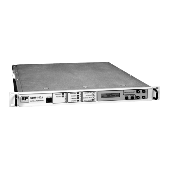
Chapter 1. INTRODUCTION This chapter provides the description, options, and specifications for the SDM-100A satellite modem, referred to in this manual as “the modem” (Figure 1-1). Figure 1-1. SDM-100A Rev. 0 1–1... -
Page 18: Purpose And Function
-30 to -55 dBm DISPLAY & KEYPAD FRONT PANEL REMOTE (OPT.) Figure 1-2. SDM-100A Block Diagram The modem provides total flexibility in selection of the following data rates: 19.2 to 128 kbit/s 1/2 rate 28.8 to 192 kbit/s 3/4 rate 33.6 to 224 kbit/s... -
Page 19: Description
SDM-100A Satellite Modem Introduction The modem interfaces with IF converter equipment operating in a 50 to 180 MHz band. The data interface options consist of RS-449/422, V.35, RS-232-C, ASYNC, and Adaptive Differential Pulse Code Modulation (ADPCM) voice. Changes in connectors for the various interfaces are accomplished by small, field-changeable connector modules. -
Page 20: Options
Introduction SDM-100A Satellite Modem Figure 1-3. Dimensional Drawing 1.3 Options For more information on the following options, refer to Appendix B. 1.3.1 ASYNC/AUPC Interface The ASYNC interface board provides the interface for terrestrial data and a single ASYNC overhead channel, along with an AUPC feature. -
Page 21: Modem Specifications
SDM-100A Satellite Modem Introduction 1.4 Modem Specifications Table 1-1 lists the operating specifications of the modem. Table 1-1. SDM-100A Specifications Modem Specifications Operating Frequency Range 50 to 180 MHz, synthesized in 2.5 kHz steps. Type of Modulation Quadrature Phase Shift Keying (QPSK), or Bi-Phase Shift Keying (BPSK). - Page 22 Introduction SDM-100A Satellite Modem Additional Modulator Specifications Output Power -5 to -30 dBm, adjustable in 0.1 dB steps. Output Spurious and Harmonics -55 dBc in 4 kHz BW in-band (50 to 180 MHz). -55 dBc in 4 kHz BW out-of-band (0 to 500 MHz).
-
Page 23: Table 1-2. Ber Performance Specification
SDM-100A Satellite Modem Introduction 1.5 BER Performance The bit energy-to-noise ratio (E ) required to achieve 10 to 10 bit error rates is listed in Table 1-2. Table 1-2. BER Performance Specification Viterbi K = 7 1/2 Rate 3/4 Rate 7/8 Rate 5.5 dB... -
Page 24: Figure 1-4. Viterbi Bit Error Rate Performance
Introduction SDM-100A Satellite Modem 1/2 RATE 3/4 RATE 7/8 RATE 10.0 11.0 (dB) Figure 1-4. Viterbi Bit Error Rate Performance 1–8 Rev. 0... -
Page 25: Figure 1-5. Sequential Bit Error Rate Performance
SDM-100A Satellite Modem Introduction 1/2 RATE 3/4 RATE 7/8 RATE 10.0 11.0 (dB) Figure 1-5. Sequential Bit Error Rate Performance Rev. 0 1–9... -
Page 26: Figure 1-6. Typical Output Spectrum
Introduction SDM-100A Satellite Modem RL -10.00 dBm *ATTEN 0 dB 10.00 dB/DIV SDM 100 64 kbit/s, 1/2 RATE QPSK VITERBI TYPICAL SDM-100A OUTPUT SPECTRUM SPAN 500.0 kHz CENTER 70.000 0 MHz ST 50 00 1 00 k 30 0 Figure 1-6. Typical Output Spectrum 1–10... -
Page 27: Chapter 2. Installation
Chapter 2. INSTALLATION This chapter provides unpacking instructions, system requirements, and external connections for the modem. 2.1 Unpacking The modem and manual are packaged in pre-formed, reusable cardboard cartons that contain foam spacing for maximum shipping protection. The circuit cards are contained in the modem chassis. -
Page 28: System Installation
Installation SDM-100A Satellite Modem 6. Check the equipment against the packing list shipped with the equipment to ensure that the shipment is complete. 7. Refer to Section 2.2 for further system installation instructions. 2.2 System Installation Install the modem as follows: 1. -
Page 29: System Requirements
SDM-100A Satellite Modem Installation 2.3 System Requirements The standard modem with all the cards installed is a full-duplex QPSK satellite modem. The system can also be configured for TX-only or RX-only. • For a TX-only system, enter the UTILITY SYSTEM menu under FUNCTION SELECT UTILITY on the front panel. -
Page 30: Figure 2-1. Typical Rack Elevation
Installation SDM-100A Satellite Modem Figure 2-1. Typical Rack Elevation 2–4 Rev. 0... -
Page 31: External Connections
SDM-100A Satellite Modem Installation 2.4 External Connections Connections between the modem and other equipment are made through five connectors. These connectors are listed in Table 2-1, and their locations are shown in Figure 2-2. The use of each connector is described in the following paragraphs. -
Page 32: Data I/O Interface (J8)
Installation SDM-100A Satellite Modem 2.4.1 DATA I/O Interface (J8) The DATA I/O interface connector is used to interface data input and output signals to and from the modem. The DATA I/O connects to the customer terrestrial equipment directly or through a protection switch. -
Page 33: Faults (J7)
SDM-100A Satellite Modem Installation 2.4.3 Faults (J7) The Fault connector on the modem is used to interface FORM-C contact closures for the purpose of fault reporting. There are three FORM-C summary fault contacts: • Modulator • Demodulator • Common equipment For further discussion on the monitored faults, refer to Chapter 3. -
Page 34: Rx If Input (Cp2)
Installation SDM-100A Satellite Modem 2.4.5 RX IF Input (CP2) This is the receive IF connector. The input impedance is 75 optional). Ω Ω For normal operation, the desired carrier signal level should be between -30 and -55 dBm. Signals between 50 and 180 MHz are selected and demodulated to produce clock and data at the DATA I/O connector. -
Page 35: Chapter 3. Operation
Chapter 3. OPERATION This chapter describes the front panel operation and clocking configurations of the modem. For remote control operation information, refer to Appendix A. 3.1 Front Panel The front panel of the modem (Figure 3-1) provides the local user interface, which is necessary to configure and monitor status of the modem. -
Page 36: Front Panel Keypad Option
Operation SDM-100A Satellite Modem 3.1.1 Front Panel Keypad Option This feature is a future option which will allow the user to plug in a hand-held keypad, and will allow access to all programming capabilities. 3.1.2 LED Indicators General modem status and summary faults are indicated by 10 LEDs on the front panel. -
Page 37: Front Panel Controls
SDM-100A Satellite Modem Operation 3.1.3 Front Panel Controls The modem is locally operated by using the front panel keypad (Figure 3-1), which consists of the following keys: [ENTER] This key is used to select a displayed function, or to execute a change to the modem’s configuration. -
Page 38: Menu System
Operation SDM-100A Satellite Modem 3.2 Menu System In order to access and execute all functions, refer to the menus in Figures 3-2 through 3-25. Use the main menu in Figure 3-2 as a quick reference for accessing all modem functions. For further configuration details, refer to Section 3.3. -
Page 39: Standard Sdm-100 Menus
SDM-100A Satellite Modem Operation 3.2.1 Standard SDM-100 Menus SDM-100 "TYPE" VER: 14.7.4 FUNCTION SELECT FUNCTION SELECT FUNCTION SELECT FUNCTION SELECT STORED REMOTE AUPC FUNCTION SELECT MONITOR FAULTS/ALARMS CONFIGURATION FLT/ALMS (Figure 3-10) UTILITY (Figure 3-7) (Figure 3-8) (Figure 3-9) CONFIGURATION UTILITY... - Page 40 Operation SDM-100A Satellite Modem This page is intentionally left blank. 3–6 Rev. 0...
-
Page 41: Configuration
SDM-100A Satellite Modem Operation 3.2.1.1 Configuration Modem configuration may be viewed or changed by entering the “CONFIGURATION” level from the “FUNCTION SELECT” menu on the front panel. After entering the “CONFIGURATION” menu, press [ ] or [ ] to select ←... -
Page 42: Figure 3-3. Configuration Modulator (Sdm-100 Operation)
Operation SDM-100A Satellite Modem SDM-100 "TYPE" FUNCTION SELECT CONFIGURATION VER: 14.7.4 CONFIGURATION MODULATOR TX-X CODE_RATE/ TX POWER LEVEL TX-IF FREQUENCY TX-IF OUTPUT TYPE (Fixed or Adj.) 50 to 180 MHz -5 to -30 dBm x = A, B, C, D, or V in 2.5 kHz steps. -
Page 43: Configuration Modulator
SDM-100A Satellite Modem Operation 3.2.1.1.1 Configuration Modulator TX-X Transmitter Rate selection. Code_Rate/Type One of four predefined transmitter code/data rate combinations may be selected: A, B, C, or D, or a variable rate selection (V). These selections must first be set up in the Utility menu. - Page 44 Operation SDM-100A Satellite Modem TX Power Level Programs the modulator output power level from -5 to -30 dBm, in 0.1 dBm steps. The high power option operates from + 5 to -20 dBm. On entry, the current transmitter power level is displayed with the flashing cursor on the first character.
- Page 45 SDM-100A Satellite Modem Operation This page is intentionally left blank. Rev. 0 3–11...
-
Page 46: Figure 3-4. Configuration Demodulator (Sdm-100 Operation)
Operation SDM-100A Satellite Modem SDM-100 "TYPE" FUNCTION SELECT CONFIGURATION VER: 14.7.4 CONFIGURATION DEMODULATOR RX-X CODE_RATE/ RX-IF FREQUENCY DESCRAMBLER DIFF. DECODER TYPE x = A, B, C, D, or V 50 to 180 MHz In 2.5 kHz steps. TX-A QPSK 1/2 64.000 kbit/s TX-B QPSK 1/2 96.000 kbit/s... -
Page 47: Configuration Demodulator
SDM-100A Satellite Modem Operation 3.2.1.1.2 Configuration Demodulator RX-X Receiver rate selection. One of four predefined receiver Code_Rate/Type decoder/data rate combinations (A, B, C, or D) or a variable rate selection (V) may be selected. These selections must first be set up in the Utility menu. - Page 48 Operation SDM-100A Satellite Modem IF Loop Back Programs the modem for IF loopback operation (test mode). When IF loopback is turned on, the demodulator input is connected to the modulator output through an internal attenuator, and the demodulator is programmed to the same frequency as the modulator.
- Page 49 SDM-100A Satellite Modem Operation This page is intentionally left blank. Rev. 0 3–15...
-
Page 50: Figure 3-5. Configuration Interface (Sdm-100 Operation)
Operation SDM-100A Satellite Modem SDM-100 "TYPE" FUNCTION SELECT CONFIGURATION VER: 14.7.4 CONFIGURATION INTERFACE TX CLOCK SOURCE TX CLOCK PHASE BUFFER CLOCK RX CLOCK PHASE AUTO TX TERRESTRIAL RX (SATELLITE) NORMAL NORMAL RX (SATELLITE) SCT (INTERNAL) INVERT INVERT SCT (INTERNAL) EXT. REFERENCE... -
Page 51: Figure 3-5. Configuration Interface Continued (Sdm-100 Operation)
SDM-100A Satellite Modem Operation ASYNC TX STOP ADPCM INTF CIRCUIT TYPE TRUNK 1 or 2 bits ON/OFF SUBSCRIBER (ASYNC only) (ADPCM only) (ADPCM only) ON HOOK/ EM CIRCUIT ENCODING TYPE OFF HOOK A-LAW ON HOOK 1, 2, 3, or 4 µ-LAW... -
Page 52: Configuration Interface
Operation SDM-100A Satellite Modem 3.2.1.1.3 Configuration Interface TX Clock Source Programs the clock source for the modem transmitter clock. “TX Terrestrial” sets the TX clock to recover timing from the incoming clock/data. “RX (Satellite)” sets the TX clock to operate from the satellite clock. - Page 53 SDM-100A Satellite Modem Operation B-Band Loop Back Programs the modem for baseband loopback operation (test mode). When baseband loopback is turned on, the data and timing signals are hard-wired (via relays) from the demodulator to the modulator on the modem side of the interface. The Data Terminal Equipment (DTE)
- Page 54 Operation SDM-100A Satellite Modem ADPCM Intf ADPCM interface ON/OFF selection. If ADPCM is set ON, the ADPCM operation is selected. If ADPCM is set OFF, then the standard RS-422 interface option is selected. Available only with the ADPCM option installed.
- Page 55 SDM-100A Satellite Modem Operation This page is intentionally left blank. Rev. 0 3–21...
-
Page 56: Figure 3-6. Configuration Local Aupc (Sdm-100 Operation)
Operation SDM-100A Satellite Modem CONFIGURATION SDM-100 "TYPE" FUNCTION SELECT LOCAL AUPC VER: 14.7.4 CONFIGURATION (AUPC only) AUPC ENABLE NOMINAL POWER MINIMUM POWER MAXIMUM POWER ON/OFF -30 to -5 dBm -30 to -5 dBm -30 to -5 dBm REMOTE CL TARGET NOISE... -
Page 57: Configuration Local Aupc
SDM-100A Satellite Modem Operation 3.2.1.1.4 Configuration Local AUPC AUPC Enable This option turns the local modem’s AUPC ON or OFF. Nominal Power This option programs the nominal power set point for AUPC from -30 to -5 dBm. Minimum Power This option programs the minimum power set point for AUPC from - 30 to -5 dBm. -
Page 58: Figure 3-7. Monitor (Sdm-100 Operation)
Operation SDM-100A Satellite Modem SDM-100 "TYPE" FUNCTION SELECT VER: 14.7.4 MONITOR RAW BER CORRECTED BER EB/N0 RECEIVE SIGNAL CURRENT Eb/N0 CURRENT RAW BER CURRENT CORRECTED BER CURRENT RECEIVE NO DATA (if carrier not locked) NO DATA (if carrier not locked) -
Page 59: Monitor
SDM-100A Satellite Modem Operation 3.2.1.2 Monitor When the “MONITOR” level is entered, press [ ] or [ ] to select the desired monitor ← → function. Each monitor function is displayed in real time as long as it is selected. -
Page 60: Faults/Alarms
Operation SDM-100A Satellite Modem 3.2.1.3 Faults/Alarms The “FAULTS/ALARMS” level is accessible from the “FUNCTION SELECT” menu. These are similar to monitor functions, as the current status is displayed. Press [ ] or [ ] to move between the Fault/Alarm groups: ←... - Page 61 SDM-100A Satellite Modem Operation This page is intentionally left blank. Rev. 0 3–27...
-
Page 62: Figure 3-8. Faults/Alarms (Sdm-100 Operation)
Operation SDM-100A Satellite Modem SDM-100 "TYPE" FUNCTION SELECT VER: 14.7.4 FAULTS/ALARMS MODULATOR DEMODULATOR TX INTERFACE RX INTERFACE CARRIER DETECT IF SYNTHESIZER IF SYNTHESIZER BUFFER CLK ACT TX CLK ACTIVITY DATA CLOCK SYN I CHANNEL BUFFER UNDERFLOW TX AUDIO CLIP I CHANNEL... -
Page 63: Modulator Faults
SDM-100A Satellite Modem Operation 3.2.1.3.1 Modulator Faults Fault/Alarm Possible Problem and Action IF Synthesizer Modulator IF synthesizer is faulted. This is considered a major alarm and will turn off the modulator output. Return the modem for repair. Data Clock Syn Transmit data clock synthesizer fault. -
Page 64: Demodulator Faults
Operation SDM-100A Satellite Modem 3.2.1.3.2 Demodulator Faults Fault/Alarm Possible Problem and Action Carrier Detect Carrier detect fault. Indicates the decoder is not locked. This is the most common fault displayed in the modem. Any problem from the input data on the modulator end of the circuit to the output of the decoder can cause this alarm. -
Page 65: Tx Interface Faults
SDM-100A Satellite Modem Operation 3.2.1.3.3 TX Interface Faults Fault/Alarm Possible Problem and Action TX Clock Activity Activity detector alarm of selected interface transmit clock. Indicates the selected TX clock is not being detected. Check the signal of the selected TX clock source to verify the signal is present. -
Page 66: Common Equipment Faults
Operation SDM-100A Satellite Modem 3.2.1.3.5 Common Equipment Faults Fault/Alarm Possible Problem and Action Battery/Clock M&C battery voltage or clock fault. Indicates a low voltage in the memory battery. Typically will be active when a modem has been Hard Reset, or the firmware has been changed. - Page 67 SDM-100A Satellite Modem Operation This page is intentionally left blank. Rev. 0 3–33...
-
Page 68: Figure 3-9. Stored Flts/Alms (Sdm-100 Operation)
Operation SDM-100A Satellite Modem FUNCTION SELECT SDM-100 "TYPE" STORED VER: 14.7.4 FLTS/ALMS MODULATOR X DEMODULATOR X TX INTERFACE X RX INTERFACE X HH:MM:SS/MM-DD-YY HH:MM:SS/MM-DD-YY HH:MM:SS/MM-DD-YY HH:MM:SS/MM-DD-YY IF SYNTHESIZER CARRIER DETECT^ BUFFER CLK ACT ^ TX AUDIO CLIP ^ DATA CLOCK SYN... -
Page 69: Stored Faults/Alarms
SDM-100A Satellite Modem Operation 3.2.1.4 Stored Faults/Alarms The modem stores the first 10 (Flt0 through Flt9) occurrences of fault status changes in each of the seven major fault categories. Each fault status change is stored with the time and date of the occurrence. Stored faults may be viewed by entering the “Stored Faults”... -
Page 70: Remote Aupc
Operation SDM-100A Satellite Modem SDM-100 "TYPE" FUNCTION SELECT REMOTE AUPC BB LOOP BACK VER: 14.7.4 REMOTE AUPC STATUS: STATUS: Key: ACCESS TO CONDITIONAL OR Parameter Information SUBMENU OPTION-DEPENDENT Figure 3-10. Remote AUPC (SDM-100 Operation) 3.2.1.5 Remote AUPC Remote AUPC Programs the modem for remote AUPC. -
Page 71: Utility
SDM-100A Satellite Modem Operation 3.2.1.6 Utility The utility functions are divided into five user categories, and provide access to the following Utility menus: • MODULATOR • DEMODULATOR • INTERFACE • SYSTEM • MODEM TYPE These menus provide a means to: •... -
Page 72: Figure 3-11. Utility Modulator (Sdm-100 Operation)
Operation SDM-100A Satellite Modem SDM-100 "TYPE" FUNCTION SELECT UTILITY MODULATOR VER: 14.7.4 UTILITY ASSIGN TRANSMIT MOD POWER MOD POWER FIXED MODULATOR TYPE FILTERS OFFSET OFFSET x = FILTER A, B, C, D, or V +0.0 dBm INTELSAT OPEN -99.9 to +99.9 dB, Fixed Status only. -
Page 73: Utility Modulator
SDM-100A Satellite Modem Operation 3.2.1.6.1 Utility Modulator Assign Transmit Filters Transmit filter display/assignment utility. Used to make filter rate reassignments. The modulator has five symbol rate filter presets. Filters are designated as A, B, C, D, and V. Note: Switching between Modem types will reset the Filter presets to their factory-defined values. - Page 74 Operation SDM-100A Satellite Modem Modulator Type Transmit Filter Type Select. Allows operator to select INTELSAT Open, CSC Closed, FDC Closed, or EFD Closed network filtering. Encoder Type Select Viterbi or Sequential encoder type. If the Sequential encoder firmware is not installed, the modem will double beep, and not allow the selection change.
- Page 75 SDM-100A Satellite Modem Operation This page is intentionally left blank. Rev. 0 3–41...
- Page 76 Operation SDM-100A Satellite Modem SDM-100 "TYPE" FUNCTION SELECT UTILITY VER: 14.7.4 UTILITY DEMODULATOR ASSIGN RECEIVE DEMODULATOR DECODER TYPE RX BPSK ORDERING FILTERS TYPE A, B, C, D, or V INTELSAT OPEN STANDARD VITERBI NON-STANDARD CSC CLOSED SEQUENTIAL FDC CLOSED RX-A QPSK 1/2 64.000 kbit/s EFD CLOSED RX-B QPSK 1/2 96.000 kbit/s...
-
Page 77: Utility Demodulator
SDM-100A Satellite Modem Operation 3.2.1.6.2 Utility Demodulator Assign Receive Filters Receive filter display/assignment utility. Used to view current filter rate assignments and to make filter rate reassignments. Refer to the previous text under “Assign TX_Filters.” The receive filters assignments are basically identical. -
Page 78: Figure 3-13. Utility Interface (Sdm-100 Operation)
Operation SDM-100A Satellite Modem SDM-100 "TYPE" FUNCTION SELECT UTILITY VER: 14.7.4 UTILITY INTERFACE RTS TX-IF TERRESTRIAL INTERFACE TYPE BUFFER PROGRAM CONTROL INTERFACE RS-422 BITS V.35 Status Only MILLI-SECONDS (ASYNC ONLY) ASYNC 2 WIRE / 4 WIRE SD SIGNAL RD SIGNAL... -
Page 79: Utility Interface
SDM-100A Satellite Modem Operation 3.2.1.6.3 Utility Interface Interface Type Displays the interface type installed in modem (RS-422, V.35, RS-232-C, ASYNC, or ADPCM). This is a status window only, and no changes can be made from this menu. Buffer Program Sets the size of the buffer. - Page 80 Operation SDM-100A Satellite Modem DM Signal Inverts the polarity of the DM signal. Select either NORMAL or INVERT (inverted) signal poarity. Available only with the ASYNC or ADPCM options. RS Signal Inverts the polarity of the RS signal. Select either NORMAL or INVERT (inverted) signal poarity. Available only with the ASYNC option.
- Page 81 SDM-100A Satellite Modem Operation This page is intentionally left blank. Rev. 0 3–47...
-
Page 82: Figure 3-14. Utility System (Sdm-100 Operation)
Operation SDM-100A Satellite Modem FUNCTION SELECT UTILITY SDM-100 "TYPE" UTILITY SYSTEM VER: 14.7.4 TIME: HH:MM:SS AM/PM REMOTE ADDRESS REMOTE BAUD RATE DATE: MM/DD/YY 4800 Current time and date. X = 1 to 255 9600 19200 EVEN 1200 2400 NONE M&C MODULE FW... -
Page 83: Utility System
SDM-100A Satellite Modem Operation 3.2.1.6.4 Utility System Time/Date Time of day and Date set/display function. The current time and date in the modem memory are displayed when selected. To set the modem time and/or date, press [ENTER]. Press ] or [ ] to position the flashing cursor over the parameter to be ←... - Page 84 Operation SDM-100A Satellite Modem M&C Module Displays M&C module firmware version. Firmware Upon entry, the date of release of this firmware will be displayed. This is a status window only. FPGA Firmware Displays firmware version of the Field Programmable Gate Array.
-
Page 85: Figure 3-15. Utility Modem Type (Sdm-100 And Type 1 Operation)
Figure 3-15. Utility Modem Type (SDM-100 and Type 1 Operation) 3.2.1.6.5 Utility Modem Type This configuration allows the user to select normal SDM-100A operation, or to direct the modem to simulate an SDM-650B by selecting Type 1 operation. The modem will then simulate an SDM-650B that contains v.274 firmware. -
Page 86: Figure 3-16. Utility Factory Setup (Sdm-100 And Type 1 Operation)
Operation SDM-100A Satellite Modem SDM-100 "TYPE" FUNCTION SELECT VER: 14.7.4 UTILITY UTILITY FACTORY SETUP Key: Factory setup should not be ACCESS TO CONDITIONAL OR Parameter Information SUBMENU OPTION-DEPENDENT changed by unauthorized persons. Failure to comply may cause modem failure. Figure 3-16. Utility Factory Setup (SDM-100 and Type 1 Operation) 3.2.1.6.6 Utility Factory Set-Up... -
Page 87: Type 1 Operation Menus
SDM-100A Satellite Modem Operation 3.2.2 Type 1 Operation Menus SDM-100 "TYPE" VER: 14.7.4 FUNCTION SELECT FUNCTION SELECT FUNCTION SELECT FUNCTION SELECT STORED FUNCTION SELECT CONFIGURATION MONITOR FAULTS/ALARMS FLT/ALMS UTILITY (Figure 3-18) (Figure 3-19) (Figure 3-20) (Figure 3-21) UTILITY MODULATOR (Figure 3-22) -
Page 88: Figure 3-18. Configuration (Type 1 Operation)
Operation SDM-100A Satellite Modem SDM-100A "TYPE" FUNCTION SELECT VER: 14.7.4 CONFIGURATION TX-X CODE_RATE/ RX-X CODE_RATE/ TX-IF FREQUENCY RX-IF FREQUENCY TYPE TYPE X = A, B, C, D, OR V X = A, B, C, D, OR V 50 to 180 MHz 50 to 180 MHz in 2.5 kHz steps... -
Page 89: Configuration: Type 1 Operation
SDM-100A Satellite Modem Operation 3.2.2.1 Configuration: Type 1 Operation TX-X Code_Rate/Type Transmitter rate selection. One of four predefined transmitter code/data rate combinations may be selected: • • • • A variable rate selection (V) can also be selected. These settings must first be set up in the Utility menu. - Page 90 Operation SDM-100A Satellite Modem RX-X Code_Rate/Type Receiver rate selection. Four predefined receiver decoder/data rate combinations are available: • • • • A variable rate selection (V) may also be selected. These settings must first be set up in the Utility menu.
- Page 91 SDM-100A Satellite Modem Operation TX Power Level Programs the modulator output power level from -5 to -30 dBm, in 0.1 dB steps. The high-power option operates from +5 to -20 dBm. On entry, the current transmitter power level is displayed with the flashing cursor on the first character.
- Page 92 Operation SDM-100A Satellite Modem B-Band Loop Back Programs the modem for baseband loopback operation (test mode). When baseband loopback is turned on, the data and timing signals are hard-wired (via relays) from the demodulator to the modulator on the modem side of the interface. The DTE...
- Page 93 SDM-100A Satellite Modem Operation Reacquisition Programs the sweep re-acquisition mode time duration. The time that is selected with this parameter is the time that the modem will remain in a narrow sweep (± 10%) after acquisition has been accomplished. After this timer runs out, the modem will return to the normal sweep.
-
Page 94: Figure 3-19. Monitor (Type 1 Operation)
Operation SDM-100A Satellite Modem SDM-100 "TYPE" FUNCTION SELECT VER: 14.7.4 MONITOR RECEIVE SIGNAL RAW BER CORRECTED BER EB/N0 CURRENT RAW BER CURRENT Eb/N0 CURRENT CORRECTED BER CURRENT RECEIVE NO DATA (if carrier not locked) NO DATA (if carrier not locked) -
Page 95: Faults/Alarms: Type 1 Operation
SDM-100A Satellite Modem Operation 3.2.2.3 Faults/Alarms: Type 1 Operation The Faults/Alarms level is accessible from the Function Select menu. Faults/Alarms are similar to Monitor functions. The Faults/Alarms level displays the current fault status of the group being displayed. Press [... -
Page 96: Figure 3-20. Faults/Alarms (Type 1 Operation)
Operation SDM-100A Satellite Modem SDM-100 "TYPE" FUNCTION SELECT VER: 14.7.4 FAULTS/ALARMS MODULATOR DEMODULATOR COMMON IF SYNTHESIZER CARRIER DETECT BATTERY/CLOCK DATA CLOCK ACT IF SYNTHESIZER -12 VOLT SUPPLY DATA CLOCK SYN DATA CLOCK SYN +12 VOLT SUPPLY I CHANNEL I CHANNEL... -
Page 97: Modulator Faults: Type 1 Operation
SDM-100A Satellite Modem Operation 3.2.2.3.1 Modulator Faults: Type 1 Operation Fault Description IF Synthesizer Modulator IF synthesizer fault. Data Clock Act Activity detector alarm of the selected interface receive clock. The interface will fall back to the satellite clock when this fault is active. -
Page 98: Figure 3-21. Stored Flt/Alms (Type 1 Operation)
Operation SDM-100A Satellite Modem FUNCTION SELECT SDM-100 "TYPE" STORED VER: 14.7.4 FLTS/ALMS CLEAR?? MODULATOR X DEMODULATOR X COMMON X STORED FAULTS HH:MM:SS/MM-DD-YY HH:MM:SS/MM-DD-YY CLEAR ?? HH:MM:SS/MM-DD-YY CARRIER DETECT IF SYNTHESIZER BATTERY/CLOCK IF SYNTHESIZER DATA CLOCK ACT -12 VOLT SUPPLY DATA CLOCK SYN... -
Page 99: Stored Faults/Alarms: Type 1 Operation
SDM-100A Satellite Modem Operation 3.2.2.4 Stored Faults/Alarms: Type 1 Operation The modem stores the first 10 (Flt0 through Flt9) occurrences of fault status changes in each of the seven major fault categories. Each fault status change is stored with the time and date of the occurrence (i.e., when a fault occurs and when it clears). -
Page 100: Utility Functions
Operation SDM-100A Satellite Modem 3.2.2.5 Utility Functions The utility functions are divided into five categories: • Modulator • Demodulator • Interface • System • Modem type utility These menus allow the user to: • Set the time and date of the modem real time clock •... - Page 101 SDM-100A Satellite Modem Operation This page is intentionally left blank. Rev. 0 3–67...
-
Page 102: Figure 3-22. Utility Modulator (Type 1 Operation)
Operation SDM-100A Satellite Modem SDM-100 "TYPE" FUNCTION SELECT UTILITY MODULATOR VER: 14.7.4 UTILITY ASSIGN TRANSMIT MODULATOR TYPE FILTERS SDM51 COMPATIBLE x = FILTER A, B, C, D, or V CSC CLOSED TX-A QPSK 1/2 [64.000 kbit/s] FDC CLOSED EFD CLOSED TX-B QPSK 1/2 [96.000 kbit/s]... -
Page 103: Utility Modulator: Type 1 Operation
SDM-100A Satellite Modem Operation 3.2.2.5.1 Utility Modulator: Type 1 Operation Assign Transmit Filters Transmit filter display/assignment utility. Used to make filter rate reassignments. The modulator has five symbol rate filter presets. Filters are designated as A, B, C, D, and V. -
Page 104: Figure 3-12. Utility Demodulator
Operation SDM-100A Satellite Modem SDM-100 "TYPE" FUNCTION SELECT UTILITY VER: 14.7.4 UTILITY DEMODULATOR ASSIGN RECEIVE DEMODULATOR BER THRESHOLD FILTERS TYPE x = FILTER A, B, C, D, or V CSC CLOSED 1.0 E-3 to 1.0 E-8 FDC CLOSED NONE RX-A QPSK 1/2 [64.000 kbit/s] EFD CLOSED RX-B QPSK 1/2 [96.000 kbit/s]... -
Page 105: Utility Demodulator Functions: Type 1 Operation
SDM-100A Satellite Modem Operation 3.2.2.5.2 Utility Demodulator Functions: Type 1 Operation Assign Receive Filters Receive filter display/assignment utility. Used to view and change current filter rate assignments. Refer to the previous text under assign transmit filters. The receive filters assignments are basically identical. -
Page 106: Figure 3-24. Utility Interface (Type 1 Operation)
Operation SDM-100A Satellite Modem SDM-100 "TYPE" FUNCTION SELECT UTILITY VER: 14.7.4 UTILITY INTERFACE INTERFACE TX CLOCK BUFFER CLOCK BUFFER SIZE TYPE PHASE AUTO EXT. REFERENCE RS422 64 to 65536 BITS NORMAL RX (SATELLITE) V.35 0 BYPASS INVERT TX TERRESTRIAL RS232... -
Page 107: Utility Interface Functions: Type 1 Operation
SDM-100A Satellite Modem Operation 3.2.2.5.3 Utility Interface Functions: Type 1 Operation Interface Type Displays the interface type (RS-422, V.35, RS-232-C, ASYNC, or ADPCM) installed in the modem. This is a status window only, and no changes can be made from this menu. -
Page 108: Figure 3-25. Utility System (Type 1 Operation)
Operation SDM-100A Satellite Modem FUNCTION SELECT UTILITY SDM-100 "TYPE" UTILITY SYSTEM VER: 14.7.4 TIME: HH:MM:SS AM/PM REMOTE ADDRESS REMOTE BAUD RATE LAMP TEST?? DATE: MM/DD/YY 4800 Current time and date. X = 1 to 255 Press [ENTER] 9600 19200 EVEN... -
Page 109: Utility System Functions: Type 1 Operation
SDM-100A Satellite Modem Operation 3.2.2.5.4 Utility System Functions: Type 1 Operation Time/Date Time of day and date set/display function. The current time and date in the modem memory are displayed when selected. To set the modem time and/or date, press [ENTER]. Press [... - Page 110 Operation SDM-100A Satellite Modem M&C Module FW Displays M&C module firmware version. Upon entry, the date of release of this firmware will be displayed. This is a status window only. FPGA Firmware Displays firmware version of the Field Programmable Gate Array (FPGA). Upon entry, the date of release of this firmware will be displayed.
-
Page 111: Figure 3-26. Rf Loopback
SDM-100A Satellite Modem Operation MODEM REQUIRES AN EXTERNAL PATH TO LOCK. THIS IS DONE EITHER AT THE MODEM INPUT, OR FROM THE SATELLITE TX = 70 MHz TRANSMIT RF CUSTOMER ENCODER/ INTERFACE EQUIPMENT DATA MODULATOR ANTENNA REMOTE SERIAL MICRO- POW ER... -
Page 112: Figure 3-27. If Loopback
Operation SDM-100A Satellite Modem TRANSMIT RF CUSTOMER ENCODER/ INTERFACE EQUIPMENT DATA MODULATOR ANTENNA REMOTE SERIAL MICRO- POWER INTERFACE AC POWER COMPUTER SUPPLY FAULT INDICATORS SDM-100A DEMODULATOR/ RECEIVE RF SATELLITE DECODER EQUIPMENT DATA MODEM Figure 3-27. IF Loopback Note: When IF loopback is turned on, the demodulator is looped back to the modulator inside the modem, and the demodulator is programmed to the same frequency as the modulator. -
Page 113: Clocking Options
SDM-100A Satellite Modem Operation 3.3 Clocking Options Methods of clocking the data from the terrestrial equipment to the satellite (and vice versa) will depend upon the application. The two most common options and recommended configurations are described in the following paragraphs. -
Page 114: Figure 3-29. Master/Master Clocking Block Diagram
Operation SDM-100A Satellite Modem Figure 3-29. Master/Master Clocking Block Diagram 3–80 Rev. 0... -
Page 115: Figure 3-30. Master/Slave Clocking Block Diagram
SDM-100A Satellite Modem Operation Figure 3-30. Master/Slave Clocking Block Diagram Rev. 0 3–81... - Page 116 Operation SDM-100A Satellite Modem This page is intentionally left blank. 3–82 Rev. 0...
-
Page 117: Chapter 4. Theory Of Operation
Chapter 4. THEORY OF OPERATION This chapter describes the theory of operation for the various components of the modem. 4.1 Modulator The modem modulator creates a QPSK or BPSK modulated carrier within the 50 to 180 MHz range from the digital data stream that is provided by the Interface section. The following subsections make up the modulator: •... -
Page 118: Figure 4-1. Modulator Block Diagram
Theory of Operation SDM-100A Satellite Modem Fault information from the modulator is sent to the host M&C, and includes: • Synthesizers out-of-lock • RF output leveled • Input data clock activity • I channel digital filter activity • Q channel digital filter activity •... - Page 119 SDM-100A Satellite Modem Theory of Operation The data signal passes to the convolutional encoder. • For Viterbi codes, the convolutional encoder encodes the data at rate 1/2. If the selected code rate is 3/4, then two of every six symbols are punctured out. For every three data bits in, there are four bits out.
-
Page 120: Figure 4-2. Bpsk Ordering, Viterbi
Theory of Operation SDM-100A Satellite Modem In the normal (or “Standard”) operation, the I channel data is output from the MUX first, followed by Q channel data. If this order of data does not match the receive BPSK ordering, the modem will not lock. The TX and RX BPSK ordering must be the same in order to get the receiver to lock. -
Page 121: Specifications
SDM-100A Satellite Modem Theory of Operation 4.1.2 Specifications Modulation Type QPSK or BPSK Data Rate Range 19.2 to 128 kbit/s 1/2 Rate, QPSK 28.8 to 192 kbit/s 3/4 Rate, QPSK 33.6 to 224 kbit/s 7/8 Rate, QPSK 9600 bit/s to 64 kbit/s 1/2 Rate, BPSK Symbol Rate Range 19.2 to 128 ks/s... -
Page 122: Demodulator
Theory of Operation SDM-100A Satellite Modem 4.2 Demodulator The modem demodulator converts a QPSK or BPSK modulated signal of 50 to 180 MHz to a demodulated baseband data stream. The demodulator then performs error correction on the data stream, using a Viterbi decoding algorithm or a sequential decoder. There also is a summary fault relay that provides a Form-C output located on the demodulator board. -
Page 123: Viterbi Decoding Theory
SDM-100A Satellite Modem Theory of Operation DIGITAL ALIAS FILTER NYQUIST IF INPUT 50 TO 180 MHz -55 TO -30 dBm IF FILTER DIGITAL ALIAS FILTER NYQUIST LOOPBACK SYNTH DIGITAL COSTAS MICRO- LOOP PROCESSOR SOFT DECISION MAPPING SYNCHRONOUS RX DATA UNIQUE WORD... -
Page 124: Figure 4-4. Viterbi Decoder Block Diagram
Theory of Operation SDM-100A Satellite Modem A set of “branch metric” values is then computed for each of the received symbol pairs, related to the probability that the received symbol pair was actually transmitted as one of the four possible symbol pairs. The “branch metrics” are then processed by the Add-Select-Compare (ASC) computer. -
Page 125: Sequential Decoding Theory
SDM-100A Satellite Modem Theory of Operation 4.2.4 Sequential Decoding Theory The sequential decoder is used in closed network applications, typically in Frequency Division Multiple Access (FDMA) satellite communications systems. The sequential decoder is optional firmware that plugs onto the demodulator/M&C/interface board. -
Page 126: Figure 4-5. Sequential Decoder Block Diagram
Theory of Operation SDM-100A Satellite Modem The syndrome input generator converts the 2-bit soft decision data into a single bit per channel, and simultaneously corrects some isolated bit errors. The data is then shifted through the syndrome shift registers, which allows the parity generator to detect bit errors. -
Page 127: Monitor And Control
SDM-100A Satellite Modem Theory of Operation 4.3 Monitor and Control A sophisticated microcontroller module is used to perform the monitor and control functions of the modem. This module is located on the demodulator board, and is referred to as the Monitor and Control (M&C). The M&C monitors the modem, and provides configuration updates to other modules within the modem when necessary. -
Page 128: Remote Interface Configuration
Theory of Operation SDM-100A Satellite Modem 4.3.4 Remote Interface Configuration All modem functions can be remotely controlled and monitored via an RS-485 (or optional RS-232-C) communications link. The 2- or 4-wire, half-duplex RS-485 interface makes it possible to operate up to 255 modems and other units on a common communications link. -
Page 129: Modem Defaults
SDM-100A Satellite Modem Theory of Operation 4.3.5 Modem Defaults The M&C has default settings that are loaded into the modem at power-up. These default settings are also loaded each time the modem has been Hard Reset. The following table lists the defaults settings for each modem configuration parameter. -
Page 130: Digital Interfaces
Theory of Operation SDM-100A Satellite Modem 4.4 Digital Interfaces The modem interface module is a daughter card that plugs onto the demodulator board. It provides the interface for terrestrial data and overhead signals, and provides the fault reporting output of the modem. -
Page 131: Figure 4-6. Rs-422 Block Diagram
SDM-100A Satellite Modem Theory of Operation 31,32 37,38 DEMOD FAULT MOD FAULT 33,34 +12V 35,36 -12V 39,40 INTF0 INTF1 1,19,20,37 Figure 4-6. RS-422 Block Diagram Table 4-1. M&C Jumper Settings (AS/4973) Jumper Position Function JP10 1 to 2 RS-485 3 to 4... - Page 132 Theory of Operation SDM-100A Satellite Modem Data received by the modem is output on the Receive Data (RD) lines, while the recovered clock is output on the Receive Timing (RT) lines. • Receive Clock NORMAL mode should be selected for applications that require the rising edge of the clock to occur in the middle of the data bit time.
-
Page 133: Connector Pinouts
SDM-100A Satellite Modem Theory of Operation Fault indicators are also provided on TTL open collector drivers on the RS-422 connector. • The TTL MOD fault indicates one of the following: MODULATOR fault COMMON EQUIPMENT fault • The TTL DEMOD fault indicates one of the following:... -
Page 134: Specification
Theory of Operation SDM-100A Satellite Modem 4.4.1.2 Specification Circuit Supported SD, ST, TT, RD, RT, DM, RR, MC, MOD FAULT, DEMOD FAULT Amplitude (RD, RT, ST, DM, RR) 2V differential into 100 ± Ω DC Offset (RD, RT, ST, DM, RR) 0.0,... -
Page 135: Figure 4-7. V.35 Interface
SDM-100A Satellite Modem Theory of Operation 31,32 INTF0 37,38 DEMOD FAULT MOD FAULT 33,34 +12V 35,36 -12V 39,40 INTF1 1, 7 Figure 4-7. V.35 Interface The clock selection is jumper selectable at JP1 on the front edge of the board. - Page 136 Theory of Operation SDM-100A Satellite Modem The Request to Send (RTS) line is hard-wired to the Clear to Send (CTS) line by JP11, pins 5 and 6, on the Demodulator/M&C card (AS/4973), since the modem does not support polled operation.
-
Page 137: Connector Pinouts
SDM-100A Satellite Modem Theory of Operation 4.4.2.1 Connector Pinouts The V.35 interface is provided on the industry standard 34-pin block or 25-pin D connector accessible from the rear panel of the modem. Screw locks are provided for mechanical security of the mating connector. -
Page 138: Specification
Theory of Operation SDM-100A Satellite Modem 4.4.2.2 Specification Circuit Supported SD, SCT, SCTE, RD, SCR, DSR, RLSD, MC, MOD FAULT, DEMOD FAULT Amplitude (RD, SCR, SCT, SD, SCTE) 0.55V pk, differential, into 100 ± Ω Amplitude (CTS, DSR, RLSD) 5V into 5000, ± 2000 ±... -
Page 139: Theory Of Operation
SDM-100A Satellite Modem Theory of Operation (TT) (SD) (RS) DEMOD FAULT MOD FAULT (RT) (ST) (DM) (CS) (RD) (RR) 33,34 +12V 35,36 -12V 37,38 INF1 39,40 INF0 Figure 4-8. RS-232-C Interface 4.4.3.1 Theory of Operation The RS-232-C interface provides a Send Timing (ST) clock signal at the modem data rate. - Page 140 Theory of Operation SDM-100A Satellite Modem The TX clock phasing choice is made from the front panel in the Interface Configuration menu. • The AUTO setting is used when there is no jitter on the clock source. • The NORMAL setting is used when standard clock and data relationships exist.
-
Page 141: Connector Pinouts
SDM-100A Satellite Modem Theory of Operation Two fault outputs are provided on dry contact Form-C relays on the Demodulator/M&C card, and are sent to the interface card. The signals are buffered and output for use in monitoring fault status, and are available on the FAULT connector on the modem rear panel. -
Page 142: Asynchronous Interface
Theory of Operation SDM-100A Satellite Modem 4.4.4 Asynchronous Interface Refer to Appendix B. 4.4.5 Terrestrial Interface Change The modem comes configured for one specific type of interface. To convert to another interface type, a field change is required. Since the modem interface module is a daughter card that plugs onto the demodulator board, it will be necessary to remove the top cover of the modem to make an interface change. -
Page 143: Chapter 5. Maintenance
Chapter 5. MAINTENANCE This chapter describes system checkout, maintenance, and troubleshooting procedures for the modem. 5.1 System Checkout The system checkout section is to be used as an aid in setting up a modem within the earth station. There are tables for use in checking to see if the E is correct, a typical output spectrum, and typical eye pattern and constellation pictures. -
Page 144: Modulator Checkout
Maintenance SDM-100A Satellite Modem 5.1.2 Modulator Checkout The first step in turning up a carrier is to set the output frequency. This is done in the CONFIGURATION menu on the front panel (refer to Chapter 3). The CONFIGURATION menu also allows the operator to set the output level, turn the output on or off, set the scrambler, differential encoder, clock source, and gives access to the test modes for system check-out. -
Page 145: Figure 5-1. Typical Output Spectrum
SDM-100A Satellite Modem Maintenance Figure 5-1. Typical Output Spectrum RL -53.0 dBm ATTEN 10 dB 1 dB/DIV 5 dB E /N of Noise 64 kbit/s 1/2 Rate QPSK SPAN 200.0 kHz CENTER 70.0000 MHz SWP 56.0 sec *RBW 3.0 kHz *VBW 3.0 Hz... - Page 146 Maintenance SDM-100A Satellite Modem Table 5-1. EFData Conversion of (S+N)/N to S/N and E Various Code Rates (dB) Code Rate 1/2 Code Rate 3/4 Code Rate 7/8 (S+N)/N -0.6 10.0 10.5 10.1 10.1 10.1 10.1 11.0 10.6 10.6 10.6 10.6 11.5...
-
Page 147: Figure 5-3. Typical Eye Constellations
SDM-100A Satellite Modem Maintenance WITH NOISE WITHOUT NOISE Figure 5-3. Typical Eye Constellations Rev. 0 5–5... -
Page 148: Test Points
Maintenance SDM-100A Satellite Modem 5.1.4 Test Points The modem does not have accessible test points. When troubleshooting is required at board level, the cover must be removed. The following is a list of test points located on the PCB, and a description of the signal that is to be present under normal operation. -
Page 149: Modulator Test Points
SDM-100A Satellite Modem Maintenance 5.1.4.2 Modulator Test Points TP 1 DATA CLOCK TTL level clock that is locked to the incoming data to the interface card. TP 2 SYMBOL CLOCK TTL level clock that is locked to the incoming clock at the interface card. -
Page 150: Fault Isolation
Maintenance SDM-100A Satellite Modem 5.2 Fault Isolation The modem has been designed so that a competent technician can isolate fault conditions without removing the modem from its location. The fault monitoring capability of the modem is designed to aid the operator in determining the cause of a failure. -
Page 151: Module Identification
SDM-100A Satellite Modem Maintenance 5.3 Module Identification The modem PCBs each have an assembly number that is marked on the board. The latest revision is stamped on the board along with the serial number. EFData tracks the hardware by the assembly number, revision, and serial number. - Page 152 Maintenance SDM-100A Satellite Modem This page is intentionally left blank. 5–10 Rev. 0...
-
Page 153: Appendix A. Remote Control Operation
FW/4969-1C and FW/4969-2C • Software version: 14.7.4 The -2 version is the PLCC (Plastic Leadless Chip Carrier) version, applicable to the SDM-100A and - 150A. The -1 version is the 28-pin DIP version, applicable to the SDM-100 and -150. A.1 General Remote controls and status information are transferred via an RS-485 (optional RS-232-C) serial communications link. -
Page 154: Message Structure
Remote Control Operation SDM-100A Satellite Modem A.2 Message Structure The ASCII character format used requires 11 bits/character: • 1 start bit • 7 information bits • 1 parity bit • 2 stop bits Messages on the remote link fall into the categories of commands and responses. -
Page 155: A.2.3 Command/Response
SDM-100A Satellite Modem Remote Control Operation A.2.3 Command/Response The command/response portion of the message contains a variable-length character sequence which conveys command and response data. If a satellite modem receives a message addressed to it which does not match the established protocol or cannot be implemented, a negative acknowledgment message is sent in response. -
Page 156: A.3 Configuration Commands/Responses
Remote Control Operation SDM-100A Satellite Modem A.3 Configuration Commands/Responses A.3.1 Modulator Modulator Command: <add/MF_nnn.nnnn'cr' Where: nnn.nnnn = Frequency in MHz, 50.0000 to 180.0000, Frequency Response: >add/MF_nnn.nnnn'cr' in 2.5 kHz steps. RF_OFF'cr''lf'] Note: When the modulator frequency is programmed, the RF Status: <add/MF_'cr'... - Page 157 SDM-100A Satellite Modem Remote Control Operation Command: <add/MOP_snn.n'cr' Where: snn.n = -30.0 to -5.0, in 0.1 steps (nominal range in Modulator Response: >add/MOP_snn.n'cr''lf'] dBm). Output Power Level Status: <add/MOP_'cr' Notes: Response: >add/MOP_snn.n'cr''lf'] 1. The nominal power range is modified relative to the value specified by the modulator power offset (MPO_).
-
Page 158: A.3.2 Demodulator
Remote Control Operation SDM-100A Satellite Modem A.3.2 Demodulator Set Demod Command: <add/DF_nnn.nnnn'cr' Where: nnn.nnnn = Frequency in MHz, 50.0000 to 180.0000, Frequency Response: >add/DF_nnn.nnnn'cr''lf'] in 2.5 kHz steps. Status: <add/DF_'cr' Response: >add/DF_nn.nnnn'cr''lf'] Demod Command: <add/ADRx_nnnn_mmm.mmm'cr' Where: Rate Preset Response >add/ADRx_nnnn_mmm.mmm'cr''lf'] x = A, B, C, D, or V (Preset designator). - Page 159 SDM-100A Satellite Modem Remote Control Operation Sweep Command: <add/SCF_snnnnn'cr' Where: snnnnn = -35000 to +35000, in 1 Hz steps. Center Response: >add/SCF_snnnnn'cr''lf'] Frequency Status: <add/SCF_'cr' Response: >add/SCF_snnnnn'cr''lf'] Sweep Command: <add/SWR_nnnnn'cr' Where: nnnnn = 0 to 70000, in 1 Hz steps.
-
Page 160: A.3.3 Interface
Remote Control Operation SDM-100A Satellite Modem A.3.3 Interface Transmit Command: <add/TC_xxx'cr' Where: xxx = INT (internal SCT clock), EXT (external TX Clock Response: >add/TC_xxx'cr''lf'] terrestrial clock), or SAT (receive satellite clock). Status: <add/TC_'cr' Response: >add/TC_xxx'cr''lf'] Transmit Command: <add/TCP_xxxx'cr' Where: xxxx = NRM (normal clock phasing), INV (inverted... - Page 161 SDM-100A Satellite Modem Remote Control Operation Interface Command: <add/SBTR_xxx'cr' Where: xxx = SUB or TRK. Subscriber/ Response: >add/SBTR_xxx'cr''lf'] Trunk Note: Only valid when ADPCM board is installed. Emulation Status: <add/SBTR_'cr' Response: >add/SBTR_xxx'cr''lf'] E & M Command: <add/EMS_n'cr' Where: n = 1 to 5, in steps of 1.
- Page 162 Remote Control Operation SDM-100A Satellite Modem ASYNC Command: <add/ROBR_nnnnn'cr' Where: nnnnn = 150, 300, 600, 1200, or 2400. Receive Response: >add/ROBR_nnnnn'cr''lf'] Overhead Note: Only valid when ASYNC board is installed with ASYNC Baud Rate Status: <add/ROBR_'cr' enabled. Response: >add/ROBR_nnnnn'cr''lf'] ASYNC Command: <add/TCCL_n'cr'...
- Page 163 SDM-100A Satellite Modem Remote Control Operation Interface Command: <add/ISMC_xxx'cr' Where: xxx = NRM or INV. MC Signal Response: >add/ISMC_xxx'cr''lf'] Command Note: Only valid when ASYNC board is installed. Interface TT Command: <add/ISTT_xxx'cr' Where: xxx = NRM or INV. Signal Response: >add/ISTT_xxx'cr''lf']...
-
Page 164: A.3.4 System
Remote Control Operation SDM-100A Satellite Modem A.3.4 System Time Of Command: <add/TIME_hh:mmxx'cr' Where: Response: >add/TIME_hh:mmxx'cr''lf'] hh = 1 to 12 (hours). mm = 00 to 59 (minutes). Status: <add/TIME_'cr' xx = AM or PM. Response: >add/TIME_hh:mmxx'cr''lf'] Date Command: <add/DATE_mm/dd/yy'cr' Where: Response: >add/DATE_mm/dd/yy'cr''lf']... - Page 165 SDM-100A Satellite Modem Remote Control Operation AUPC Command: <add/MINP_snn.n'cr' Where: snn.n = -30.0 to -5.0, in 0.1 steps (nominal range in Minimum Response: >add/MINP_snn.n'cr''lf'] dBm). Power Limit Status: <add/MINP_'cr' Note: The nominal power range is modified relative to the value Response: >add/MINP_snn.n'cr''lf']...
-
Page 166: A.4 Status Commands/Responses
Remote Control Operation SDM-100A Satellite Modem A.4 Status Commands/Responses A.4.1 Configuration Modulator Command: <add/MCS_'cr' Config Response: >add/MCS_'cr' Status RF_xxx'cr' RF Output (ON/OFF) MF_nnn.nnnn'cr' Modulator Frequency MR_nnnn_mmm.mmm'cr' Modulator Rate AMRA_nnnn_mmm.mmm'cr' Preset 'A' Assignment AMRB_nnnn_mmm.mmm'cr' Preset 'B' Assignment AMRC_nnnn_mmm.mmm'cr' Preset 'C' Assignment AMRD_nnnn_mmm.mmm'cr'... - Page 167 SDM-100A Satellite Modem Remote Control Operation Modulator/ Command: <add/MCP_'cr' Coder Response: >add/MCP_'cr' Config MOM_xxxxxxx'cr' Modem Operation Mode Program MT_xxxx'cr' Modulator Type Status MET_xxx'cr' Modulator Encoder Type MF_nnn.nnnn'cr' Modulator Frequency MR_nnnn_mmm.mmm'cr' Modulator Rate MPO_snn.n'cr' Modulator Power Offset MOP_snn.n'cr' (Note 1) Modulator Output Power...
- Page 168 Remote Control Operation SDM-100A Satellite Modem Demodulato Command: <add/DCS_'cr' r Config Response: >add/DCS_'cr' Status DF_nnn.nnnn'cr' Demodulator Frequency DR_nnnn_mmm.mmm'cr' Demodulator Rate ADRA_nnnn_mmm.mmm'cr' Preset 'A' Assignment ADRB_nnnn_mmm.mmm'cr' Preset 'B' Assignment ADRC_nnnn_mmm.mmm'cr' Preset 'C' Assignment ADRD_nnnn_mmm.mmm'cr' Preset 'D' Assignment ADRV_nnnn.mmm.mmm'cr' Preset 'V' Assignment...
- Page 169 SDM-100A Satellite Modem Remote Control Operation Demod/ Command: <add/DCP_'cr' Decoder Response: >add/DCP_'cr' Config MOM_xxxxxxx'cr' Modem Operation Mode Program BERT_xxxx'cr' BER Threshold Status DT_xxxx'cr' Demodulator Type DDT_xxx'cr' Demodulator Decoder Type DF_nnn.nnnn'cr' Demodulator Frequency DR_nnnn_mmm.mmm'cr' Demodulator Rate DE_xxx'cr' Descrambler Enable (ON/OFF) DDEC_xxx'cr'...
- Page 170 Remote Control Operation SDM-100A Satellite Modem Interface Command: <add/ICS_'cr' Config Response: >add/ICS_'cr' Status TC_xxx'cr' Transmit Clock (Source) TCP_xxxx'cr' Transmit Clock Phase RCP_xxxx'cr' Receive Clock Phase BBL_xxx'cr' Baseband Loop Back BC_xxx'cr' Buffer Clock (Source) IBP_xxx'cr' Interface Buffer Programming IBS_nnnnn'cr' Interface Buffer Size...
- Page 171 SDM-100A Satellite Modem Remote Control Operation Automatic Command: <add/ACS_'cr' Uplink Response: >add/ACS_'cr' Power LPC_xxx'cr' Local AUPC Enable (ON/OFF) Control NOMP_-nn.n'cr' Nominal Power Value (-5.0 to -30.0) (AUPC) MINP_-nn.n'cr' Minimum Power Limit (-5.0 to -30.0) Config MAXP_-nn.n'cr' Maximum Power Value (-5.0 to -30.0) Status ENSP_n.n'cr'...
- Page 172 Remote Control Operation SDM-100A Satellite Modem Common Command: <add/CES_'cr' Equipment Response: >add/CES_'cr' Status M&C_xxx'cr' Monitor & Control Module (OK/FLT) INT_xxx'cr' Data Interface Module (OK/FLT) BAT_xxx'cr' Battery/Clock (OK/FLT) +5_xxx'cr' +5V Power Supply (OK/FLT) +12_xxx'cr' +12V Power Supply (OK/FLT) -12_xxx'cr' -12V Power Supply (OK/FLT)
- Page 173 SDM-100A Satellite Modem Remote Control Operation Current Command: <add/CSV_'cr' Where: Sweep Response: >add/CSV_snnnnn'cr''lf'] Value x = < or > (data modifier to indicate that the sweep offset value is less than or greater than the returned value). s = + or - (sweep offset from center).
- Page 174 Remote Control Operation SDM-100A Satellite Modem Bulk Consol Command: <add/BCS_'cr' This command causes bulk modem status to be returned. Status Response: >add/BCS_p1,p2,p3, . . . pn'cr''lf'] To reduce the length of the response, message parameter data are returned without identifiers. However, parameter identification can be determined by order of return.
- Page 175 SDM-100A Satellite Modem Remote Control Operation Parameter 20 (p20): Demodulator preset B assignment (ref. "ADRB_" command). p20 = nnnn_mmm.mmm, code rate/data rate in kbit/s. Parameter 21 (p21): Demodulator preset C assignment (ref. "ADRC_" command). p21 = nnnn_mmm.mmm, code rate/data rate in kbit/s.
- Page 176 Remote Control Operation SDM-100A Satellite Modem "APD_" command). (Note 1) p43 = n, where 'n' is '0' (off) or '1' (on). Parameter 44 (p44): ADPCM Subscriber/Trunk Emulation (ref. "SBTR_" command). (Note 1) p44 = n, where 'n' is '0' (Subscriber) or '1' (Trunk).
- Page 177 SDM-100A Satellite Modem Remote Control Operation p64 = xxxx, where 'xxxx' is the currently programmed parity. Parameter 65 (p65): ASYNC Overhead Communications Type (ref. "OCT_" command). (Note 2) p65 = n, where 'n' is '0' (RS232) or '1' (RS485). Parameter 66 (p66): Interface Wire Type (ref. "IWt_"...
- Page 178 Remote Control Operation SDM-100A Satellite Modem Change Command: <add/CS_'cr' Where: The 'x' character is defined as follows: Status Response: >add/CS_x'cr''lf'] '@' = no change since last BCS_ and BCSF_ polls. 'A' = BCS_ response has changed since last BCS_ poll.
-
Page 179: A.4.2 Error Performance
SDM-100A Satellite Modem Remote Control Operation A.4.2 Error Performance Raw BER Command: <add/RBER_'cr' Where: Response: >add/RBER_xm.mE-ee'cr''lf'] x = < or > (data modifier to indicate that the error rate is less than or greater than the returned value). m.m = 1.0 to 9.9 (error rate mantissa). -
Page 180: A.5 Stored Faults
Remote Control Operation SDM-100A Satellite Modem A.5 Stored Faults Information on stored faults is returned when requested. If no stored fault exists for a given fault number, the words “NO Fault” will be returned instead of the normal time/date status information. - Page 181 SDM-100A Satellite Modem Remote Control Operation Reed- Command: <add/RSSF_#'cr' Solomon Response: >add/RSSF_# hh:mm:ss Unavailable MM/DD/YY'cr' Unavailable Seconds (FLT/OK) Seconds UNASEC_xxx'cr''lf'] Bulk Consol Command: <add/BCSF_'cr' This command causes all modem fault status to be Status Response: >add/BCSF_abcdefghijkl'cr''lf'] returned. To reduce the length of the response, fault status...
- Page 182 Remote Control Operation SDM-100A Satellite Modem Character 'h': Interface transmit side faults character 2. Bit 6 = 1 always. Bit 5 = Selected Transmit Clock Activity. Bit 4 = ADPCM Transmit Audio Clip. (See Note) Bit 3 = reserved. Bit 2 = reserved.
-
Page 183: Appendix B. Options
Appendix B. OPTIONS This appendix provides information about the following options: • Asynchronous/Automatic Uplink Power Control (AUPC Interface) • ADPCM Voice Interface • Reed-Solomon Codec B.1 AUPC Interface The asynchronous (ASYNC) interface board provides the interface for terrestrial data and a single ASYNC overhead channel. -
Page 184: Rev
Options SDM-100A Satellite Modem Figure B-1. ASYNC/AUPC Block Diagram B–2 Rev. 0... - Page 185 SDM-100A Satellite Modem Options The ASYNC interface PCB also provides its own Doppler buffer, which has a maximum depth of 32 ms at the highest terrestrial data rate. Buffer fill status can be checked in the monitor menu on the front panel of the modem. Depth selection and centering of the buffer are provided in the CONFIG INTERFACE menu.
-
Page 186: B.1.1 Theory Of Operation
Options SDM-100A Satellite Modem 4. Once modem A has re-acquired the carrier, it will start sending commands to modem B to achieve the desired E . During this time, modem B will be sending commands to modem A to either increase or decrease power to maintain modem B’s target E... -
Page 187: B.1.1.4 Demultiplexer Operation
SDM-100A Satellite Modem Options B.1.1.4 Demultiplexer Operation The operation of the DEMUX section is similar to the operation of the MUX side. Data, including overhead, is received from the Demodulator card in the modem at the overhead rate. The DEMUX locates the framing in the overhead and locks to the frame sync pattern generated by the multiplexer on the transmitting end. -
Page 188: B.1.1.6 Loop Timing Operation
Options SDM-100A Satellite Modem B.1.1.6 Loop Timing Operation A loop timing option is provided. When loop timing is selected, the Doppler buffer output clock is forced to the clock by the M&C. An M&C-controlled MUX switches the Send Timing (ST) pin to output the clock. -
Page 189: B.1.1.10 Valid Async Baud Rates
SDM-100A Satellite Modem Options B.1.1.10 Valid ASYNC Baud Rates The ASYNC baud rates are limited by the terrestrial data rates. The following tables show the relationships between data and baud rates. If DR <= 15.999K Max baud rate is 150 If DR <= 31.999K... -
Page 190: B.1.2.1 Top Cover Removal
Options SDM-100A Satellite Modem B.1.2.1 Top Cover Removal The following 16 screws must be removed from the modem in order to take off the top cover: • Five screws located on each side • Three screws at the front •... -
Page 191: B.1.3 Front Panel Operation
SDM-100A Satellite Modem Options B.1.3 Front Panel Operation The following sections describe the additional front panel operations that are specific to the ASYNC interface. These options are shown in the menu tables in Chapter 3, along with the standard menu windows. -
Page 192: B.1.3.2 Modulation Configuration
This option allows the user to chose from a 9.6 to 224 kHz mode of operation with the ASYNC overhead enabled. BPSK 1/2, QPSK 1/2, 3/4, and 7/8 are also supported. With the ASYNC set to OFF, this option works in the standard SDM-100A mode. B.1.3.3 Demodulation RX Rate and Type This option allows the user to chose from a 9.6 to 224 kHz mode of... -
Page 193: B.1.3.5 Specifications
SDM-100A Satellite Modem Options B.1.3.5 Specifications Terrestrial Interface Data Rate 9.6 to 224 kHz Overhead 1/16 overhead Coding BPSK 1/2, QPSK 1/2, 3/4, 7/8 ASYNC Interface ASYNC Interface Types RS-485 or RS-232-C 2-wire or 4-wire Channel Formats Data bits 5 to 8... -
Page 194: B.2 Adpcm Voice Interface
Options SDM-100A Satellite Modem B.2 ADPCM Voice Interface The ADPCM voice interface is capable of providing a single duplex voice channel and Ear and Mouth (E&M) signaling data transmission. The interface also provides an EIA STD RS-422 interface which is user selectable. This optional interface replaces the RS- 422, RS-232, or V.35 interfaces. -
Page 195: Figure B-3. Adpcm Block Diagram
SDM-100A Satellite Modem Options Figure B-3. ADPCM Block Diagram Rev. 0 B–13... -
Page 196: B.2.1.1 Multiplexer
Options SDM-100A Satellite Modem B.2.1.1 Multiplexer The ADPCM interface provides a 6-wire, RJ11 phone connector on the back panel for the analog input. The input is a full-duplex four-wire input, with two additional pins for E&M signaling (Refer to Section B.2.3 for the RJ11 pinout specifications). The audio input is transformer-coupled with a 600 input load. -
Page 197: B.2.1.3 Protection Switch
SDM-100A Satellite Modem Options The analog signal from the PCM decoder then passes through a programmable level control circuit (user selectable from the front panel). An RX Clip detect indicator in the FAULT RX menu is provided, which indicates a reception of an excessive signal. The audio output level is user-selectable from -20 to 10 dBm, in 1 dB steps. -
Page 198: B.2.2 Front Panel Operation
RS-422 interface option is selected. Circuit Type This option refers to the emulation mode of the SDM-100A ADPCM interface. When the subscriber is selected, the SDM-100A interface is configured as a subscriber circuit. When the trunk is selected, the SDM-100A interface is configured as a trunk. -
Page 199: B.2.2.4 Utility/Interface
SDM-100A Satellite Modem Options B.2.2.4 Utility/Interface With ADPCM turned off, the RS-422 signals SD, RD, RR, and DM can be inverted, if desired. B.2.2.5 TX Alarm Indication With the ADPCM option turned on, the TX alarm LED will come on if an excessive input level is sensed on the TX+ and TX- lines of the interface. -
Page 200: B.2.3 Specifications
Options SDM-100A Satellite Modem B.2.3 Specifications Voice Encoding Audio Encoding CCITT G.711 and G.721 PCM or ADPCM Audio Encoding Rate 64, 32, or 16 kbit/s (user-selectable) Audio Encoding Type CCITT G.711 A-Law or µ-Law (user-selectable) Voice Interface Audio Interface Type 600Ω... -
Page 201: B.3 Reed-Solomon Codec
SDM-100A Satellite Modem Options B.3 Reed-Solomon Codec The Reed-Solomon Codec firmware works in conjunction with the interface card to provide concatenated, convolutional encoding and decoding. Refer to Figure B-4 for a block diagram of the Reed-Solomon Codec. The two main sections of the Codec that will be included in the theory of operation are the Reed-Solomon encoder (Section B.3.2.1) and the Reed-Solomon decoder... -
Page 202: Figure B-5. Reed-Solomon Encoder Section Block Diagram
Options SDM-100A Satellite Modem SERIAL MUXDATA PARALLEL TXSATDAT SYNCHRONOUS SYNCHRONOUS CODEC UNIQUE WORD PARALLEL (SERIAL) TO SERIAL FIFO INTERLEAVER SCRAMBLER (ENCODER SECTION) INSERTION CONVERTER MUXCLK TXSATCLK INTERLEAVER ADDRESS GENERATOR RS TIMING CONTROLLER Figure B-5. Reed-Solomon Encoder Section Block Diagram The data and clock signals (MUXDATA and MUXCLK) come from the multiplexer on the interface PCB, and are sent to the Reed-Solomon encoder section through connector JP2. -
Page 203: Figure B-6. Reed-Solomon Code Page Format
SDM-100A Satellite Modem Options Since errors from the Viterbi decoder usually occur in bursts, a block-interleaver with a depth of 4 is used in accordance with the INTELSAT-308 Rev. 6B specification. The interleaver has the effect of spreading out the errors across blocks of data, instead of concentrating the errors in a single block of data. -
Page 204: B.3.2 Reed-Solomon Decoder
Options SDM-100A Satellite Modem B.3.2 Reed-Solomon Decoder Refer to Figure B-7 for a block diagram of the Reed-Solomon decoder section. The Reed-Solomon decoder section includes the following circuits: • Serial/Parallel Converter • Synchronous FIFO • RAM Interleaver • Parallel/Serial Converter •... - Page 205 SDM-100A Satellite Modem Options Refer to Figure B-6 for the Reed-Solomon code page format. The outer Codec reads the data in blocks of n bytes and recalculates the check bytes that were appended by the encoder. If the recalculated data bytes do not match the check bytes received, the Codec makes the necessary corrections to the data within the data block.
- Page 206 Options SDM-100A Satellite Modem This page is intentionally left blank. B–24 Rev. 0...
-
Page 207: Glossary
Glossary The following is a list of acronyms and abbreviations that may be found in this manual. Acronym/ Definition Abbreviation Ω Ohms Ampere Alternating Current Adjust ADPCM Adaptive Differential Pulse Code Modulation Automatic Gain Control Automatic Offset Control Add-Select-Compare ASYNC Asynchronous AUPC Automatic Uplink Power Control... - Page 208 Glossary SDM-100A Satellite Modem Data Circuit Terminating Equipment Direct Digital Synthesis Demod Demodulator DEMUX Demultiplexer Data Mode Digital Signal Processing Data Signal Rate Data Terminal Equipment E&M Ear and Mouth Bit Energy-to-Noise Ratio EFData Compatible Electronic Industries Association Electro-Magnetic Compatibility...
- Page 209 SDM-100A Satellite Modem Glossary Return Material Authorization Read-Only Memory Receiver Ready Ready to Send Receive Timing Request to Send Receive (Receiver) Serial Clock Receive Serial Clock Transmit SCTE Serial Clock Transmit External Send Data Signal-to-Noise Ratio Send Timing Test Point...
- Page 210 Glossary SDM-100A Satellite Modem This page is intentionally left blank. g–4 Rev. 0...
-
Page 211: Metric Conversions
METRIC CONVERSIONS Units of Length Unit Centimeter Inch Foot Yard Mile Meter Kilometer Millimeter 1 centimeter — 0.3937 0.03281 0.01094 6.214 x 10 0.01 — — 1 inch 2.540 — 0.08333 0.2778 1.578 x 10 0.254 — 25.4 1 foot 30.480 12.0 —... - Page 212 2114 85281 WEST TH STREET TEMPE ARIZONA 480 • 333 • 2200 PHONE 480 • 333 • 2161...
Need help?
Do you have a question about the SDM-100A and is the answer not in the manual?
Questions and answers