
Related Manuals for LEGRAND Mosaic Manageable switch


Summary of Contents for LEGRAND Mosaic Manageable switch
- Page 1 Manageable Mosaic switch Installation and User Guide G I G A B I T P o E M a n a g e a b l e M o s a i c s w i t c h INSTALLATION AND CONFIGURATION GUIDE...
-
Page 2: Important Notice
This document is provided for informational purposes only, and Legrand does not guarantee the accuracy, adequacy, quality, validity or completeness of the information contained in this document. - Page 3 Manageable Mosaic switch Installation and User Guide Table of Contents 1 Introduction ..........................7 1.1 Overview ...............................7 1.2 General Characteristics ........................8 1.3 Manageable Mosaic switch Shipped Components ................10 1.4 Front & Side panel components......................10 1.4.1 LED Indications.........................11 1.5 Remote Management Options ......................12 2 Hardware Installation......................
- Page 4 Manageable Mosaic switch Installation and User Guide 4.2 LAN Configuration via the LCS - FTTO Init Application..............51 4.2.1 Running the LCS - FTTO Init application ................51 4.2.2 Configuring the IP and Community Parameters ...............52 4.2.3 Changing the Password ......................52 4.3 Default Settings of the manageable Mosaic switch ................53 4.3.1 Restoring manageable Mosaic switch Default Settings............53 4.3.2 Changing manageable Mosaic switch Factory Default Settings..........54 4.3.3 Restoring manageable Mosaic switch Factory Default Settings..........55...
- Page 5 Manageable Mosaic switch Installation and User Guide Table of Figures Figure 1-1 manageable Mosaic switch ................7 Figure 1-2 manageable Mosaic switch Front view............10 Figure 1-3 manageable Mosaic switch Side view.............11 Figure 3-1 Login Window via the Web Browser..............16 Figure 3-2 Port configuration, Properties and Status tabs..........17 Figure 3-3 Administration tab, Copper Port Configuration..........19 Figure 3-4 Administration &...
- Page 6 Manageable Mosaic switch Installation and User Guide Figure 4-8 Changing Factory Defaults via Embedded web interface ....... 54 Figure 4-9 Restoring Factory Defaults via Embedded web interface ....... 55 Figure 4-10 Changing Management Interfaces..............56 Figure 4-11 Changing Management Interfaces-Services..........56 Figure 5-1 Management menu, Access List tab ..............
-
Page 7: Introduction
• High power embedded management providing SNMP agent, Web (full Java applet) and Telnet • Remote management via Legrand's enhanced Embedded web interface application, Web browser and Telnet • Highly secured in-band access via IP access list, secure NMS path, passwords and optional HTTPS •... -
Page 8: General Characteristics
Manageable Mosaic switch Installation and User Guide General Characteristics Table 1-1 manageable Mosaic switch Characteristics Ports 1 to 4 10/100/1000BaseT. (external user Auto-negotiate, auto MDI, and polarity ports) 100 meter (330 Feet) distance over TP cables Cat5e and higher F/O SFP Uplink Interface –... - Page 9 Upload/download device configuration. Special features key activation. Set-up and testing Secured remote initial set-up via LCS - FTTO Init (Legrand remote device initialization application). Power Supply AC input voltage: 100–240 VAC, 50/60Hz Manageable Mosaic switch Power Consumption: 8 Watts, without PoE...
-
Page 10: Manageable Mosaic Switch Shipped Components
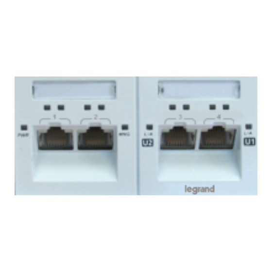
Manageable Mosaic switch Installation and User Guide Manageable Mosaic switch Shipped Components The manageable Mosaic switch is shipped with the following components: Manageable Mosaic switch • Mosaic power supply. • Front & Side panel components manageable Mosaic switch front panel contains LED indicators for Ports 1–4 as well as for the Uplink Ports (Power, Management and the PoE LEDs are also located on the front panel. -
Page 11: Led Indications
Manageable Mosaic switch Installation and User Guide Cooling Plate Front Panel Uplink 1 RJ 45 ethernet port Uplink 1 RJ45 Port Shield Terminal Uplink 2 SFP Port Main DC Power Connector Figure 1-3 manageable Mosaic switch Side view (2) The two RJ45 built-in LEDs, part of Uplink 1 RJ45 connector, are not active in the manageable Mosaic switch 1.4.1 LED Indications Table 1-2 lists the LED indicators and their description. -
Page 12: Remote Management Options
Manageable Mosaic switch Installation and User Guide Remote Management Options The manageable Mosaic switch can be managed via any of the following two management interfaces: The Embedded web interface Web Management application - from any Web browser - as an applet •... -
Page 13: Hardware Installation
Manageable Mosaic switch Installation and User Guide 2 2 H a r d w a r e H a r d w a r e I n s t a l l a t i o n I n s t a l l a t i o n Overview The manageable Mosaic switch features a compact design with a low mounting depth that fits into standard 45x90 or larger faceplates and ducts. -
Page 14: Device Management
/ 2000 / XP / Vista / 7 platform, Linux or Solaris. This software requires prior installation of the Java JRE1.6 minimum. Remote management can also be conducted from any Web browser which has access to the Legrand device network. The Web browser launches a complete Embedded web interface GUI using a Java applet (see Section 3.2). -
Page 15: Management Passwords Scheme
Manageable Mosaic switch Installation and User Guide 3.1.2 Management Passwords Scheme Legrand devices can be managed in several ways: with the Embedded web interface application, through Web access or via Telnet. Each way has its own password scheme as follows: •... -
Page 16: Using Radius Server Password Authentication
Radius server and not in each individual device. Telnet is used to direct a Legrand manageable device to seek password authentication from the Radius server while logging in from a Web browser. (See Section 0) Port Level Configuration Port configuration is done via port view windows. -
Page 17: Port Details And Status
Manageable Mosaic switch Installation and User Guide 3.3.1 Port Details and Status The Port View screen shows information about the port, connection type and status. To view this information, click the Properties and Status tabs. Figure 3-2 Port configuration, Properties and Status tabs The Port View configuration window includes the following tabs, depending on port type. -
Page 18: Configuring The Port Name
Manageable Mosaic switch Installation and User Guide Table 3-2 Port Configuration Options Parameter Description MAC Security: Allows individual ports to be disabled. (Copper ports only) QoS: Allows setting the Quality of Service parameters of the port. (Copper ports only) Statistics: Displays various statistics regarding traffic, port usage, and packets. -
Page 19: Changing Port Settings
Manageable Mosaic switch Installation and User Guide Table 3-3 Factory Default Port Configuration Values Parameter Description F/O SFP Uplink port: Port Status – On Auto Negotiate – Enabled Speed – Depends on A/N results Duplex – Depends on A/N results Flow Control –... - Page 20 Manageable Mosaic switch Installation and User Guide Table 3-4 Administration tab, Copper Port Parameters Copper Port Parameters Description Status Disables / Enables the port; Options: On, Off Mode Port speed and duplex setting. --Auto-negotiate – the port is set to negotiate speed and duplex mode with the link partner.
-
Page 21: Figure 3-4 Administration & Sfp Tabs, Sfp Port Configuration
Manageable Mosaic switch Installation and User Guide Figure 3-4 Administration & SFP tabs, SFP Port Configuration Table 3-5 Administration & SFP tabs, SFP Port Parameters Administration & SFP Description Port Parameters Status Disables / Enables the port; Options: On, Off Speed Displays 1000M or 100M, in accordance with the SFP plugged in transceiver. -
Page 22: Power Over Ethernet (Poe)
Manageable Mosaic switch Installation and User Guide Administration & SFP Description Port Parameters Serial Number Temperature Monitored Transceiver internal temperature. (data available only if the SFP transceiver supports DDM (Digital Diagnostic Monitoring) Tx Power Monitored Transceiver Transmitted Power. (Data available only if the SFP transceiver supports DDM (Digital Diagnostic Monitoring) Rx Power... - Page 23 Manageable Mosaic switch Installation and User Guide Table 3-6 PoE Parameters Parameter Description Status The left selection tab indicates that the port is open for PoE connections (will supply power if a PD is connected). The right field indicates whether or not power is being supplied to the port.
-
Page 24: Mac Security
Manageable Mosaic switch Installation and User Guide Table 3-6 PoE Parameters Parameter Description As Class 0 30.0 Watts Consumption Displays the actual power being consumed by the PD device connected to the port. Voltage Displays the voltage supplied by the PoE Power Supply to the manageable Mosaic switch. -
Page 25: Figure 3-6 Port View Menu, Mac Security Tab
Manageable Mosaic switch Installation and User Guide Figure 3-6 Port View menu, MAC Security tab MAC Security Configuration Fields: MAC Address 1-3 list displays the MAC address entries belonging to that port in the • look-up table. Approved MAC field displays the specific MAC address to be secured (the MAC •... -
Page 26: Figure 3-7 Port View Menu, Qos Tab
Manageable Mosaic switch Installation and User Guide 3.3.7 QoS The packet flow through each port is defined by the Ingress / Egress Policy. manageable Mosaic switch provides three criteria that determine the policy: QoS priority information • Rate Limit • 802.1Q based VLANs •... - Page 27 Manageable Mosaic switch Installation and User Guide To define QoS Rate Limits: 1. Click on the Ingress PRI0 field to set its value, or on Ingress PRI1 through Ingress PRI3 to set their value according to PRI0. Table 3-7 Rate Limit Parameters Parameter Available options Egress rate:...
-
Page 28: Embedded Web Interface Menu System
Manageable Mosaic switch Installation and User Guide Embedded web interface Menu system The Embedded web interface main screen provides all devices and port configuration screens plus a summary of events and fault analysis options. The screen provides a graphic view of the manageable Mosaic switch device including color indications on ports and LEDs to indicate status, as in Figure 3-8. - Page 29 Manageable Mosaic switch Installation and User Guide Menu Option Description Provides access to the following tabs and fields: ❧ Global Configuration – Aging (16 Sec; 300 Sec; 1800 Sec; or No Aging), Learning (select Enable or Disable), PONL (not available), Priority Policy (select Scheduled 8421 or Scheduled 1111).
-
Page 30: Port Indications
Manageable Mosaic switch Installation and User Guide The device level configuration options are accessed by clicking the appropriate icon on the left side of the screen. The port level configuration menus are accessed by clicking on the specific port in the graphic view. - Page 31 Manageable Mosaic switch Installation and User Guide the port, port access is open Green with Red lock – Port connected and blocked by the activated security NOTE: Red lock icon is used in case of two blocking events. First when 802.1x port is enabled by manageable Mosaic switch but not yet authorized.
-
Page 32: Device Configuration Menus
Manageable Mosaic switch Installation and User Guide Device Configuration Menus The icons on the left provide device level information and configuration options. Clicking the appropriate icons will open the requested information/configuration window, to enable configuration of the manageable Mosaic switch unit. Each configuration page includes several tabs. -
Page 33: System Device Information
Manageable Mosaic switch Installation and User Guide 3.5.1 System Device Information Figure 3-12 System View menu, Properties tab The Properties tab of displays the device Description, Up Time and allows Name, Location and Contact information to be assigned to the device. Assigning these device details helps the system manager locate and identify devices in the network. -
Page 34: Inventory
Manageable Mosaic switch Installation and User Guide 3.5.2 Inventory Figure 3-13 System View menu, Inventory tab The Inventory tab displays information about the device hardware. Max PoE power specifies the maximum power that may be sourced through the port’s PoE 3.5.3 Power Supply Figure 3-14 System View menu, Power Supply tab The Power Supply tab displays information about the power supply type, model and the nominal power... -
Page 35: Factory Defaults
Manageable Mosaic switch Installation and User Guide NOTE: It is not recommended to change the default voltage thresholds. Threshold alerts are only generated when the limits are crossed. To change the Temperature or Voltage limits: 1. Enter the Management application at a Technician level. 2. -
Page 36: Radius Server
Manageable Mosaic switch Installation and User Guide 3.5.6 RADIUS Server Figure 3-18 System View menu, RADIUS Server tab The RADIUS Server tab displays the current RADIUS server details. RADIUS server details can be edited from a Telnet connection. RADIUS authentication supported EAP-MD5 only. 3.5.7 Remote Software Reset The unit may be remotely reset at any time. -
Page 37: Vlan Mode
Manageable Mosaic switch Installation and User Guide priority 3 egress, followed by four frames from priority 2, followed by two frames from priority 1 and last one frame from priority 1. If level of forwarding is similar between the ports, it is recommended to use priority option 1111. -
Page 38: Q Vlan Membership Configuration
Manageable Mosaic switch Installation and User Guide 3.6.3 802.1Q VLAN Membership Configuration The 802.1Q VLAN Membership tab defines the VLAN IDs (VIDs) and the port membership for each of the VLANs. For practical reasons, only up to 64 VLANs may be defined in the IS-2, with VIDs ranging from 1 to 4095. -
Page 39: Q Port Settings
Manageable Mosaic switch Installation and User Guide 3.6.4 802.1Q Port Settings The 802.1Q Port Settings tab should reflect the condition (tagged/untagged) of the traffic expected on the associated port. For an access port, the default VID for the port should match with the only VID associated with the port in the previous tab (802.1Q VLAN Membership). - Page 40 Manageable Mosaic switch Installation and User Guide Table 3-11 802.1Q VLAN Tag Configuration Selected [ ] Deselected [ ] Ing. Tag Removes 802.3ac tag (or double tag) on tagged Ingressing frames are Remove ingressing frames. not modified. Egr. Tag Removes tag from egressing frames. Frames are transmitted Remove unmodified.
-
Page 41: Port Based Vlan
Manageable Mosaic switch Installation and User Guide 3.6.5 Port Based VLAN Figure 3-24 Features Menu, Port Based VLAN tab Port Based VLAN is a simple way to designate a specific VLAN association for each port by itself. This option is useful in managing sensitive ports that should not be accessible to other ports, or limited ports that should only be able to access the uplink port. -
Page 42: Rapid Spanning Tree Protocol (Rstp) Configuration
Manageable Mosaic switch Installation and User Guide This is equivalent to the native VLAN in Cisco terminology. To Configure Transparent VID: 1. Click on the Features icon and select the from the Features menu the Transparent VID tab. 2. Check Enable to activate the Transparent VID feature. 3. -
Page 43: Figure 3-26 Rstp Settings Tab
Manageable Mosaic switch Installation and User Guide To configure RSTP Click on the Features icon and select from the Features menu the RSTP • Settings tab. The following screen is displayed: Figure 3-26 RSTP Settings tab Note: The tab displays the factory default RSTP settings. Update the following fields as required: •... -
Page 44: Igmp
Manageable Mosaic switch Installation and User Guide Figure 3-27 RSTP Ports Configuration tab Priority: Priority of the port for the spanning tree algorithm. A lower number is • regarded as higher priority. Enter a value between 16 – 240, in increments of 16. Enable: Activate or deactivate (Check/No Check) the port to participate in the •... -
Page 45: Remote Device Configuration
1. Start HyperTerminal application used by PC. (Legrand recommends Tara Term) 2. Connect the CLI serial cable acquired from Legrand between the switch CLI port and a serial port on your computer. (if used Serial to USB adaptor, connect cable to one of the computer USB ports) 3. -
Page 46: Configuring The Ip And Community Parameters
Manageable Mosaic switch Installation and User Guide Figure 4-2 Hyper Terminal Boot Sequence NOTE: The actual appearance or values may differ from version to version or per system configuration 4.1.1 Configuring the IP and Community Parameters The manageable Mosaic switch unit is shipped with the following defaults: DHCP Disabled •... - Page 47 Manageable Mosaic switch Installation and User Guide 1. Enter a Terminal Emulation application as described in previous section. 2. To change password, one need to halt the boot sequence Press any key within the five second countdown period, in order to enter the configuration mode. The password prompt appears.
- Page 48 Manageable Mosaic switch Installation and User Guide Please enter new boot parameters SNMP get community [public] - SNMP set community [private] - TFTP server address [192.168.0.13] - FTP user [HighPerf] - FTP password [highperf] - TFTP filename [wp68x_040104.bin] – Boot operation [1: Download, 2: Run] – 2 Modify the above or continue? [M/C] - c You will be prompted to change the SNMP Community String.
- Page 49 Manageable Mosaic switch Installation and User Guide Boot operation [1: Download, 2: Run] - 2 Modify the above or continue? [M/C] - c Updated parameters appear here Storing updated boot record . . . done Initializing bootloader telnet interface Copy image to RAM ..... . done XXX Firmware V2.90.01 (Build Date and time) Management agent running.
-
Page 50: The Ping Command
For example, X (case sensitive) which is for the 802.1X protocol and then press enter. 3. When prompted, type the License key you received from Legrand then press enter. 4. When prompted to Modify or Continue, type C to continue. - Page 51 Manageable Mosaic switch Installation and User Guide LAN Configuration via the LCS - FTTO Init Application 4.2.1 Running the LCS - FTTO Init application N order to run the LCS - FTTO Init application, double click the program icon to invoke the application. The following screen is displayed.
-
Page 52: Configuring The Ip And Community Parameters
Manageable Mosaic switch Installation and User Guide Figure 4-5 LCS - FTTO Init Password prompt dialog Type in the default Legrand password: “mypass” and click OK. The LCS - FTTO Init screen is displayed. Figure 4-6 LCS - FTTO Init Main Screen 4.2.2 Configuring the IP and Community Parameters... -
Page 53: Default Settings Of The Manageable Mosaic Switch
Manageable Mosaic switch Installation and User Guide 1. On the LCS - FTTO Init screen, click the File menu, and choose Change Password. The following dialog tab is displayed. Figure 4-7 Changing the LCS - FTTO Init password 2. In the Password field, enter your current password. (The default password is “mypass”). -
Page 54: Changing Manageable Mosaic Switch Factory Default Settings
Manageable Mosaic switch Installation and User Guide 4.3.2 Changing manageable Mosaic switch Factory Default Settings The manageable Mosaic switch factory default settings provide the basic switch configuration of port status and management, in which all ports and management are open and accessible. The factory default settings may be changed only by technicians (user level: Technician), in cases higher level of security is required. -
Page 55: Restoring Manageable Mosaic Switch Factory Default Settings
Manageable Mosaic switch Installation and User Guide 3. The new factory defaults will be activated after the next Restore Factory Default command. 4.3.3 Restoring manageable Mosaic switch Factory Default Settings 1. Log in to the LCS - FTTO Init application. 2. -
Page 56: Figure 4-10 Changing Management Interfaces
Manageable Mosaic switch Installation and User Guide Figure 4-10 Changing Management Interfaces 3. Under Management Interfaces, make another selection from the Services field drop down list. Figure 4-11 Changing Management Interfaces-Services Page 56 of 87 SUMMARY... -
Page 57: Device Security
Manageable Mosaic switch Installation and User Guide 5 5 D e v i c e S e c u r i t y D e v i c e S e c u r i t y Securing Management Access There are three ways to remotely manage the manageable Mosaic switch device: from the Embedded web interface application, via any Web browser or Telnet. -
Page 58: Community String / Passwords
Manageable Mosaic switch Installation and User Guide 5.1.1 Community String / Passwords The community string is part of the SNMP packet. The SNMP agent will not respond to SNMP packets whose community string does not match its internal community string. The community string is an alphanumeric string of up to 15 alphanumeric characters. -
Page 59: Management Interfaces
Manageable Mosaic switch Installation and User Guide Figure 5-1 Management menu, Access List tab 2. Click Add, type the IP address of the remote manager’s workstation from which access will be allowed in the new window and click OK. Repeat for each additional IP address to be added (up to eight). -
Page 60: Management Access (Secure Nms) Path
Manageable Mosaic switch Installation and User Guide 5.1.5 Management Access (Secure NMS) Path The in-band management path can be secured by limiting the remote access through either user ports, backbone ports or all ports. By default, the NMS path is not secured, allowing access from all ports. To change the Secure NMS Path: 1. -
Page 61: Web Management User's Authentication
Manageable Mosaic switch Installation and User Guide 5.1.7 Web Management User’s Authentication Legrand manageable devices can be configured to seek user level password authentication from a central Radius server, such as from a Freeradius, Winradius or Radiator server, while logging in from a Web browser. -
Page 62: Figure 5-4 The Port View Window Mac Security Tab
Manageable Mosaic switch Installation and User Guide segment. When that specific MAC address does not exist on the look-up table, the port is blocked to all the devices. An example of this is a researcher who has a number of LAN devices (a PC, a printer, a notebook, testing equipment, etc.) hooked-up to a "local lab segment"... -
Page 63: X Port Based Network Access Security
Manageable Mosaic switch Installation and User Guide Status field displays the port security status (disable, port forwarding, or port blocked). • When disabled appears in the Status field, this means that the MAC security is disabled. When port forwarding or port blocked appears in the Status field, this means that the MAC security is enabled and that specific port is either forwarding or blocked in accordance to the MAC security algorithms. -
Page 64: Figure 5-5 802.1X Access Authentication Scheme
Manageable Mosaic switch Installation and User Guide Authenticator Authentication Server 802.1 X Supplicant clients Figure 5-5 802.1X Access Authentication Scheme The 802.1X Supplicant workstation is the device that needs authentication in order to access the network. This device must have operational 802.1X Supplicant service. Consult the network administrator to assure that the 802.1X Supplicant is installed and properly configured on the workstation(s). -
Page 65: Figure 5-6 Port View Window, 802.1X Tab
Manageable Mosaic switch Installation and User Guide NOTE: If you type show radius the Server IP address will be displayed followed by the Shared secret hidden by *** (three asterisks). The factory default for the Server IP address is 1.2.3.4 and the Shared secret is *** (three asterisks). 1. -
Page 66: Secure Http Protocol (Https)
Manageable Mosaic switch Installation and User Guide 1. From the Port View window, expand the 802.1X tab. 2. Click the Mode list and select Enable. 3. Click Apply and in the confirmation window click Yes. Repeat this procedure for each required port. The 802.1X Authentication Security Protocol is now enabled on the desired port(s). -
Page 67: Figure 5-8 Https Enabled Icon
Manageable Mosaic switch Installation and User Guide 5.2.3.2 Enabling HTTPS Figure 5-8 HTTPS Enabled icon Page 67 of 87 SUMMARY... -
Page 68: Monitoring And Analysis
Manageable Mosaic switch Installation and User Guide 6 6 M o n i t o r i n g a n d A n a l y s i s M o n i t o r i n g a n d A n a l y s i s The manageable Mosaic switch provides monitoring and analysis functions on both device and port level: Device level –... -
Page 69: Device Level – Event Log
Manageable Mosaic switch Installation and User Guide Device Level – Event Log 6.2.1 Viewing Recorded Events The last 64 events are stored in the device and are available for display at any time through the Event Log window, located at the bottom of the Embedded web interface main screen. The Event list is cleared when turning on or resetting the device. -
Page 70: Event Filter
Manageable Mosaic switch Installation and User Guide Each trap notification consists of: A unique index number • Event date and time stamp • Event description • Event source • Severity (notify, minor, major) • Acknowledge (yes or no) • Event Levels and Color codes: The record is colored according to its severity: Notify (cyan) •... -
Page 71: Port Level Statistics And Rmon Counters
Manageable Mosaic switch Installation and User Guide Events may be filtered according to different parameters and can help the network manager focus on specific events. The filter operates according to the following parameters: Dates, Time, Port Number, Severity and Acknowledged / Unacknowledged events. To filter the displayed events: 1. -
Page 72: Port Monitoring
Manageable Mosaic switch Installation and User Guide In addition to RMON information, statistics for RX packets and counters for TX packets can be monitored for each port. To display the port RMON information, RX statistics and TX counter: 1. From the Embedded web interface main screen, click the icon of the Port of interest. The Port View window appears. -
Page 73: Figure 6-5 Port View Window, Monitor Tab
Manageable Mosaic switch Installation and User Guide Figure 6-5 Port View window, Monitor tab 3. Select the Port Monitoring Mode from the Mode list described in the following table: Table 6-1 Port Monitoring Mode Options Option Description None Port monitoring mode not enabled. Egress Only Only egress frames are copied to the destination port. -
Page 74: Updating Firmware Versions
Manageable Mosaic switch Installation and User Guide 7 7 U p d a t i n g F i r m w a r e V e r s i o n s U p d a t i n g F i r m w a r e V e r s i o n s General The manageable Mosaic switch firmware comprises three elements, each updated separately: Image –... - Page 75 Manageable Mosaic switch Installation and User Guide Remote Firmware Update via LCS - FTTO Init 1. Launch the LCS - FTTO Init application. 2. Modify the SNMP Get / Set Community parameters (if necessary). 3. Update the IP address of the TFTP server that will be used to download new TFTP software versions to the device.
-
Page 76: Remote Firmware Update Via Embedded Web Interface
Manageable Mosaic switch Installation and User Guide Remote Firmware Update via Embedded web interface Figure 7-2 File Operations Window 1. From the Embedded web interface main screen, click on Files. The Files window appears as shown in Figure 7-2. 2. In the File Server tab update the IP address of the File Server that will be used to download new firmware versions to the device (The specified IP must have a running TFTP server program). - Page 77 Manageable Mosaic switch Installation and User Guide - FTTO Bulk Firmware Update - FTTO Bulk is a remote firmware update software that allows updating multiple devices simultaneously, without the need to manually connect to each device. Updating firmware using the LCS - FTTO Bulk software: 1.
- Page 78 Manageable Mosaic switch Installation and User Guide Figure 7-4 LCS - FTTO Bulk Targets screen 6. In the Auto Discovery area, enter a Start IP and End IP. The devices to be updated must be in that IP range (For example, to update to update three devices ending in 151, 152 and 153, set the Start IP as 151 and End IP as 153).
- Page 79 Each add-on feature is represented by a single letter. Multiple features can operate simultaneously. When a firmware license key code is assigned by Legrand, it will be a single code that covers all the add-on features (existing ones as well as new features being added).
-
Page 80: Activating The Special Add-On Feature(S) License Key
NOTE: The letters are case sensitive and should be entered as a string without any intervening spaces or punctuation. 4. Click on the Key field and enter the license key exactly as received it from Legrand Representative (it is recommended to cut-and-paste the license key to avoid font and case problems) then click Apply. - Page 81 (Embedded web interface and Web management, following the restart step) If the validation key indicates fail, then re-check the feature string and license key and re-start the key activation process. If the validation key still does not pass, please contact the Legrand Representative. Page 81 of 87...
-
Page 82: Telnet
Manageable Mosaic switch Installation and User Guide 8 8 T e l n e t T e l n e t General Telnet enables remote management of a single IS-2 unit as well as remote configuration of any number of units by running Telnet script files created for that purpose. Run Telnet 1. -
Page 83: Selecting The Static Ip Address Of The Device
Manageable Mosaic switch Installation and User Guide Figure 8-1 Telnet Commands IS 2> set port ? Usage: set port port_num on|off|10|100|hdx|fdx|an|man set port port_num flowcontrol on|off set port port_num egtagins|egtagrem|ingtagrem on|off set port port_num vlanfilter|egdoubletag on|off set port port_num name new_name set port port_num vid default_vid Examples: set port 2 fdx - change port 2 duplex mode to full-duplex... -
Page 84: Changing User Level Passwords Via Telnet
Manageable Mosaic switch Installation and User Guide 8.4 Changing User Level Passwords via Telnet 1. From the Start menu, type Run Telnet followed by a space then type the IP address of the target device (exact syntax according to the operating system). 2. -
Page 85: Changing Mac Security Via Telnet
Manageable Mosaic switch Installation and User Guide approximately 60 seconds. To resume the Telnet session you must re-connect and log in again. To redirect a Legrand manageable device to check management access passwords locally rather than via the Radius server: Type the Telnet command set http password followed by any of the user level access words •... - Page 86 Manageable Mosaic switch Installation and User Guide Index 802.1Q VLAN ..........36 Remote Management Options ....12 Membership..........38 Management Access List .......58 Port Configuration........39 Management Access Path ......60 Setup ............37 Secure NMS Path........60 802.1X ........61, 63–66, 63–66 Monitoring and Analysis .........68 Access List............58 Passwords Address Migration...........37 Community String....46, 52, 58, 74, 75...
- Page 87 Manageable Mosaic switch Installation and User Guide Page 87 of 87...
Need help?
Do you have a question about the Mosaic Manageable switch and is the answer not in the manual?
Questions and answers