
Related Manuals for LEGRAND Raritan MasterConsole MCD-104-DUAL


Summary of Contents for LEGRAND Raritan MasterConsole MCD-104-DUAL
- Page 1 MasterConsole® Digital DUAL Dual Display Cat5 KVM switches User Guide v1.0 Copyright © 2020 Raritan, Inc. MCD-DUAL-UserGuide-0A-v1.0 November 2020 255-20-0011-00...
- Page 2 This document contains proprietary information that is protected by copyright. All rights reserved. No part of this document may be photocopied, reproduced, or translated into another language without express prior written consent of Raritan, Inc. © Copyright 2020 Raritan, Inc. All third-party software and hardware mentioned in this document are registered trademarks or trademarks of and are the property of their respective holders.
-
Page 3: Table Of Contents
Contents Chapter 1 Introduction Overview ..............................1 Features ................................ 2 Package Contents ............................2 Specifications ..............................2 Front View ..............................4 Rear View ..............................4 Chapter 2 Installation Console Connection ............................6 Select Proper MDCIMs or MDUTPs ......................7 Computer Connection ..........................8 Chapter 3 Hotkeys Hotkey Summary Table .......................... - Page 4 Contents Viewing Firmware Version ......................... 20 Port Configuration ............................20 Video Adjustment ............................20 Chapter 5 Borderless Mouse Switching Setup ................................21 Enable Borderless Mouse Switching ......................23 Using Mouse Switching ..........................24 Chapter 6 KVM Extension Console Extension ............................25 PC/Server Extension ...........................
-
Page 5: Chapter 1 Introduction
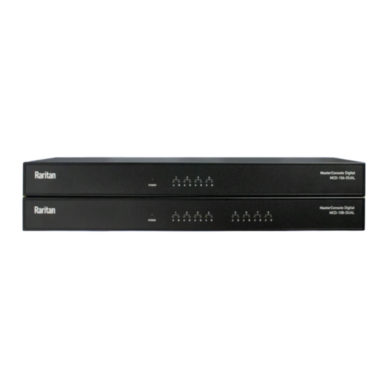
Chapter 1 Introduction In This Chapter Overview ....................... 1 Features ........................ 2 Package Contents ....................2 Specifications ......................2 Front View ......................4 Rear View ......................4 Overview MCD-DUAL switch MCD-104-DUAL and MCD-108-DUAL is a series of KVM (keyboard/video/mouse) switch that enables you to control multiple computers from a single set of keyboard, mouse, and dual-monitor. -
Page 6: Features
Chapter 1: Introduction Features • Console : dual DVI-I (analog & digital) + 2x USB Type-A • Support high video resolution up to 1920 x 1200@60Hz (VGA), 1920 x 1080@60Hz Channel select: 4/8 port two colors of LEDs to indicator each port •... - Page 7 Chapter 1: Introduction Computer Connections (Dual View) Hot-Key Console Selection OSD menu Keyboard 1 x USB Type A Female (White) Mouse 1 x USB Type A Female (White) Console Port Video 2 x DVI-I Female (White) Audio 1 x 3.5mm Audio Jack (Black) Connectors Direct 8 x RJ45 Female (Black)
-
Page 8: Front View
Chapter 1: Introduction Front View White LED lights on after powering on the MCD-DUAL. Power LED "inactive" channels with LEDs light off. Channel LEDs "active" channels with White LEDs light on. "being accessed" channels with Green LEDs light on. Rear View... - Page 9 Chapter 1: Introduction Connect the power cord. Power Socket Toggle the power on or off. Power Switch Connect a USB keyboard. USB Port (keyboard) Connect a USB mouse. USB Port (mouse) Connect audio input devices, such as speakers or Audio Output Port headphone.
-
Page 10: Chapter 2 Installation
Chapter 2 Installation Note: Please turn off all MCD-DUAL and computers before system installation. In This Chapter Console Connection ....................6 Select Proper MDCIMs or MDUTPs ..............7 Computer Connection ..................8 Console Connection Connect a USB keyboard/mouse, speaker and monitors to the connectors on the MCD-DUAL. -
Page 11: Select Proper Mdcims Or Mdutps
Chapter 2: Installation Select Proper MDCIMs or MDUTPs Choose appropriate MDCIMs or MDUTP cables according to your computer's video port and audio requirements. MCD CIM type Video type Audio transmission MDUTP cables Support analog audio MDCIM-HDMI HDMI Support digital audio MDCIM-DVI NO support MDCIM-DP... -
Page 12: Computer Connection
Chapter 2: Installation Computer Connection One-tier Connection Plug the MDCIM or MDUTP cable's USB connectors into one of the • computer's USB ports. • Plug the MDCIM or MDUTP cable's video connectors into the computer's video ports. • Optionally, plug the MDUTP cable's audio connector into the computer's audio output port. - Page 13 Chapter 2: Installation Two-tier Connection Step A Plug the MDCIM-DVI cable's USB connectors into the 2nd-tier MCD-DUAL’s • USB Keyboard port. • Plug the MDCIM-DVI cable's DVI connectors into the 2nd-tier MCD-DUAL’s Monitor A port. • Connect the MDCIM-DVI to "Channel 1: RJ45 Port A" of the 1st-tier MCD-DUAL by using a standard network patch cable (Cat5e/6 UTP).
- Page 14 Chapter 2: Installation...
-
Page 15: Chapter 3 Hotkeys
Chapter 3 Hotkeys In This Chapter Hotkey Summary Table ..................11 Hotkey Summary Table Hotkeys are executed using only the keyboard. The default hotkey is [Scroll Lock] and can be changed in OSD menu. Keying Hotkey command must be completed with 6 seconds, or it will be aborted if exceeding. - Page 16 Chapter 3: Hotkeys Hotkey Command Function Description Press the hotkey three times to trigger the OSD. With the Hotkey > Hotkey > Hotkey Enter OSD default hotkey "Scroll Lock", you should press: Scroll Lock > Scroll Lock > Scroll Lock Press 'Hotkey' twice, then the channel number, and press Enter.
-
Page 17: Chapter 4 On-Screen Display Interface
Chapter 4 On-Screen Display Interface After turning on the device, the login screen displays. For initial login, use the built-in administrator account and password. You CANNOT remove the built-in administrator and user accounts, but you can change their passwords or rename any user accounts. -
Page 18: Login Screen
Chapter 4: On-Screen Display Interface Login Screen After turning on the device, the login screen displays. For initial login, use the built-in administrator account and password. 1 Device ID The model name of your device. 2 User Port The ID number of your console ... -
Page 19: 2Nd-Tier Selection Menu
Chapter 4: On-Screen Display Interface 1 Model Name Your MCD-DUAL's model name 2 Selected Channel The number of the channel that is being accessed 3 Page Information The current page number and total pages 4 Login ID The currently used login ID ... -
Page 20: Setup
Chapter 4: On-Screen Display Interface Setup On the Selection Menu, press F1. The SETUP Menu displays. - Page 21 Chapter 4: On-Screen Display Interface Field Options/Values Function PSSL High/ Middle / Low PSSL: Adjust the sensitivity level of borderless mouse switching. Mouse Switch ON or OFF Turn on or off the borderless mouse switching function of the MCD-DUAL switch.
-
Page 22: User Configuration
Chapter 4: On-Screen Display Interface User Configuration On the SETUP Menu, press F5. The User Configuration Menu displays. MCD-DUAL provides one administrator and 15 user accounts. Note: Operation Key "F1" is not available to setup admin’s Port Access • right. •... -
Page 23: Port Access Setup
Chapter 4: On-Screen Display Interface Important: It is strongly recommended to change the admin password. Make a note of it and keep it in a secure place. If you forget the password, contact the local dealer for RMA service. To rename a user account and/or change the password: 1. -
Page 24: Viewing Firmware Version
Chapter 4: On-Screen Display Interface Viewing Firmware Version Press F5 on the Selection Menu page. The firmware information displays. Port Configuration On the Selection Menu, press F3. The Port Configuration Menu displays. Note: Before enabling borderless mouse switching, you must set the port’s resolution the same as the corresponding computer video output. -
Page 25: Chapter 5 Borderless Mouse Switching
Chapter 5 Borderless Mouse Switching The function is for channel switching by the mouse cursor hitting the left or right edge of display borders, and then the MCD-DUAL will switch to prior or next channel. Note1: Default setting is OFF. Borderless mouse switching is only available for 1st-tier computers. - Page 26 Chapter 5: Borderless Mouse Switching 3. Set the port’s new resolution as same as the corresponding computer video output. 4. Calibrate the mouse cursor after each port’s resolution reset by pressing Hotkey > Hotkey > H > Enter. In the Display Settings: 1.
-
Page 27: Enable Borderless Mouse Switching
Chapter 5: Borderless Mouse Switching 2. Choose “Adjust Resolution”, then drag the primary monitor icon to the left and make sure the corresponding video output is connected to the “RJ45 Port A”. Finally align these two monitor icons to the top. In Mouse Settings: 1. -
Page 28: Using Mouse Switching
Chapter 5: Borderless Mouse Switching 2. On the Selection Menu, press F1, then the SETUP Menu displays. 3. Turn on borderless mouse switching. Using Mouse Switching 1. Move the mouse cursor hitting the left of monitor border, and then the MCD-DUAL will switch to prior channel. -
Page 29: Chapter 6 Kvm Extension
Chapter 6 KVM Extension The Cat5 Reach DVI HD KVM extender can locate the user up to 330 feet (100 meters) apart from a PC/server and KVM switch. There are two types of Cat5 Reach DVI HD devices: one is the transmitter (C5R-DVI-HD-TX), and the other is the receiver (C5R-DVI-HD-RX). - Page 30 Chapter 6: KVM Extension 9. Use a Cat5e/6 cables up to 330 feet (100 meters) long to connect the transmitter and receiver. Plug either end of the cable into the RJ-45 LINK ports. Secondary Monitor Connection 1. Use a DVI cable to connect the DVI port (Monitor B) of the MCD-DUAL and DVI-IN port of the second C5R-DVI-HD-TX.
-
Page 31: Pc/Server Extension
Chapter 6: KVM Extension 4. Use a Cat5e/6 cables up to 330 feet (100 meters) long to connect the transmitter and receiver. Plug either end of the cable into the RJ-45 LINK ports. PC/Server Extension 1. Primary Video Output Connection: Connect the first MDCIM-DVI to the "... - Page 32 Chapter 6: KVM Extension d. Use Cat5e/6 cables up to 330 feet (100 meters) long to connect the transmitters and receivers. Plug either end of the cable into the RJ-45 LINK ports.
-
Page 33: Chapter 7 Maintenance
Chapter 7 Maintenance In This Chapter Firmware Upgrade Procedures ................29 Resetting to Factory Defaults ................33 Firmware Upgrade Procedures The KVM switch provides the firmware upgrade for the following functions: USB Host: Update for USB host chip on KVM switch. The firmware filename •... - Page 34 Chapter 7: Maintenance 6. Use the micro-USB cable to connect KVM firmware update port and the USB port of computer which runs the firmware update utility. 7. The utility will scan the KVM programmer automatically.
- Page 35 Chapter 7: Maintenance 8. Select the target by enabling the check box, for example "USB Host", and click the file browsing button to select the firmware file to update. 9. Select the firmware file to update. 10. Click the "Program" button to start firmware programming.
- Page 36 Chapter 7: Maintenance 11. A status bar is shown under the panel to indicate the update progress. 12. The firmware is updated successfully.
-
Page 37: Resetting To Factory Defaults
Chapter 7: Maintenance 13. After updating, you must restore the device. Power on the device, then press "Ctrl+Shift+F10" before log-in 14. Press "Enter" to restore the device. Resetting to Factory Defaults 1. Press F4 to log out and show the Login screen. 2. -
Page 38: Appendix A Disclaimer
Appendix A Disclaimer Information in this document is subject to change without notice. The manufacturer does not make any representations or warranties (implied or otherwise) regarding the accuracy and completeness of this document and shall in no event be liable for any loss of profit or any other commercial damage, including but not limited to special, incidental, consequential, or other damages. -
Page 39: Index
Index 2nd-tier Selection Menu • 15 Package Contents • 2 PC/Server Extension • 27 Port Access Setup • 19 Port Configuration • 20 Borderless Mouse Switching • 12, 21 Rear View • 4 Computer Connection • 8 Resetting to Factory Defaults • 12, 33 Console Connection •...
Need help?
Do you have a question about the Raritan MasterConsole MCD-104-DUAL and is the answer not in the manual?
Questions and answers