Table of Contents
Advertisement
Quick Links
Advertisement
Table of Contents

Related Manuals for Hologic ThinPrep


Summary of Contents for Hologic ThinPrep
- Page 2 ThinPrep Imaging System ® Review Scope Operator’s Manual OLOGIC 250 C AMPUS RIVE , MA 01752 USA ARLBOROUGH : 1-800-442-9892 1-508-263-2900 : 1-508-229-2795 HOLOGIC For Use With Version 6.x.y Software MAN-03352-001...
- Page 3 Hologic shall indem- nify Customer for the compensatory damages paid by Customer to discharge the personal injury judgment with respect to Product.
- Page 5 Operation Summary and Clinical Information The ThinPrep ® Imaging System...
- Page 6 (Autoscan). The Cytotechnologist determines specimen adequacy and the presence of infections during the review of the 22 fields of view presented by the ThinPrep Imaging System. Either of two methods can be used to determine specimen adequacy. The first method is to count cells and determine the average number of cells in the 22 fields of view presented by the Imager.
- Page 7 The laboratory Technical Supervisor should establish individual workload limits for personnel using the ThinPrep Imaging System. The maximum daily limit specified is only an upper limit and should never be used as an expectation for daily productivity or as a performance target.
- Page 8 Center Trial Evaluating the Primary Screening Capability of the ThinPrep Imaging System” was to show that routine screening of ThinPrep Pap Test slides using the ThinPrep Imaging System is equivalent to a manual review of ThinPrep slides for all categories used for cytologic diagnosis...
-
Page 9: Lsil
Cytopathology. Their experience levels in Cytopathology ranged from 6 to 12 years. Two of the adjudicators were from university practices and one adjudicator was from a private medical center. ® The volumes for the adjudicator’s institutions ranged from 12,000 to 30,000 ThinPrep Pap Tests annually. - Page 10 Table 3: Adjudicated Review Versus Imager Review LSIL+ Descriptive Diagnosis Summary for Each Site and All Sites Combined. Sensitivity is a percent of “true” LSIL+ (combined LSIL, HSIL, SQ CA and GL CA) slides classified in either study arm as LSIL+ and specificity is a percent of “true” Non-LSIL+ (combined Negative, ASCUS, AGUS) slides classified in either study arm as Non-LSIL+.
- Page 11 The results presented in Table 4 show that the difference between sensitivities of the Imager Review and Manual Review arms for HSIL+ for all sites combined was not statistically significant with a 95% confidence interval of -1.1% to +12.6%. The observed difference between sensitivities for HSIL+ varied among the sites from –2.5% with a 95% confidence interval of (–15.4%;...
- Page 12 Table 7: 6x6 “True AGUS” Contingency Table For All Sites Combined All 10 Cases Determined To Be AGUS By Adjudication Unadjudicated Manual Review Arm Diagnosis ASCUS AGUS LSIL HSIL TOTAL ASCUS AGUS LSIL HSIL TOTAL Among the 10 cases determined by the adjudication panel to be AGUS, 4 (40.0%) cases in the Imager Review arm and 3 (30.0%) cases in the Manual Review arm were diagnosed as AGUS and 4 (40.0%) cases in the Imager Review arm and 2 (20.0%) cases in the Manual Review arm were diagnosed as Negative.
- Page 13 ThinPrep Imaging System, to their diagnostic results obtained from their independent blinded review of the entire cell spot on the ThinPrep Pap Test slides. All of the reviews were performed in an independent and blinded manner. The test materials consisted of 33 archival PreservCyt-preserved cervical samples that had been previously diagnosed as AGUS or cancer.
- Page 14 Cytopathologist for further review. * *In the intended use of the ThinPrep Imaging System (Imager), the Cytopathologist would perform a full manual slide review of each of these cases.
- Page 15 (17/58) (8/58) (-9/58) (9520/9569) (9548/9569) (28/9569) (18.1, 42.7) (6.1, 25.4) (-25.9, -5.0) (99.3, 99.6) (99.7, 99.9) (0.2, 0.4) *95% Confidence Interval ® All ThinPrep slides that produced discordant unsatisfactory determinations (Manual Review arm MAN-03938-001 Rev. 002 page 11 of 23...
- Page 16 3 different methods as follows: (1) Manual assessment of specimen adequacy on the entire microscope slide based on ThinPrep Bethesda System 1991 criteria; (2) Using the “diameter” method of Bethesda System 2001, which requires that the Cytotechnologist counts cells in 10 fields of view along the diameter of the cell spot and calculate the number of cells on the slide;...
- Page 17 +0.3% Imager 84.4% 97.0% 74.4% 99.8% ® The clinical study data show that the screening rates achieved with the ThinPrep Imaging System resulted in sensitivity or specificity values that fall within acceptable limits. MAN-03938-001 Rev. 002 page 13 of 23...
- Page 18 Record results and triage appropriately An example of workload scenario for ThinPrep Pap slides using the ThinPrep Imaging System: 100 FOV review only = 50 slides (100 x 0.5 = 50) 30 FOV review + FMR = 45 slides (30 x 1.5 = 45) Total number of slides screened = 95 (50 FOV only and 45 FOV + FMR) ...
- Page 19 One thousand two hundred sixty (1260) slides were prepared on a ThinPrep 5000 processor and were reviewed independently by a Cytotechnologist and confirmed by a Pathologist. All cytologic diagnoses were determined in accordance with the Bethesda System 2001 criteria for all slides .
-
Page 20: Percentages Are Rounded To The Nearest
Clinical Study Results Tables 17 through 20 present the comparison of Laboratory true positive and negative rates for ASC-US+, LSIL+, ASC-H+, and HSIL+. Table 17: Laboratory Imager-Assisted Review Results vs. Laboratory Manual Review Results for the Specimens with Reference Diagnosis of ASC-US+ In the study, there were 467 specimens with Reference Diagnosis of ASC-US+ (combined ASC-US, AGUS, LSIL, ASC-H, HSIL, and Cancer) and 770 specimens with Reference Diagnosis of NILM. - Page 21 Table 18: Laboratory Imager-Assisted Review Results vs. Laboratory Manual Review Results for the Specimens with Reference Diagnosis of LSIL+ In the study, there were 327 specimens with Reference Diagnosis of LSIL+ (combined LSIL, ASC-H, HSIL, and Cancer) and 910 specimens with Reference Diagnosis of (combined NILM, ASC-US, and AGUS). In this table, “Positive”...
- Page 22 Table 19: Laboratory Imager-Assisted Review Results vs. Laboratory Manual Review Results for the Specimens with Reference Diagnosis of ASC-H+ In the study, there were 147 specimens with Reference Diagnosis of ASC-H+ (combined ASC-H, HSIL, and Cancer) and 1,090 specimens with Reference Diagnosis of (combined NILM, ASC-US/AGUS, and LSIL). In this table, “Positive”...
- Page 23 (83.1% to 90.5%) (74.2% to 83.3%) (3.7% to 12.7%) (88.5% to 90.7%) (89.4% to 91.5%) (-1.9% to 0.1%) In the study, there were 1.83% (23/1260) ThinPrep 5000 slides with UNSAT results by Adjudication. MAN-03938-001 Rev. 002 page 19 of 23...
- Page 24 Agreement among Laboratory Cytotechnologists/Pathologists The following tables indicate the extent to which the laboratory Cytotechnologists/Pathologists at a given site agreed amongst themselves on the diagnosis, comparing the Imager-assisted review to the manual review. Tables are provided for ASC-US+ and ASC-H+. Note that since one site had only two CT/Pathologist pairs, the three-way agreement analysis is available for just two sites, with 840 total specimens.
- Page 25 The rate of agreement between the Imager-assisted review result and the manual review result from the previous table is presented below. PPA is the positive percent agreement, percent of specimens of ASC-H+ diagnosis with Imager-assisted review by a majority of laboratory CT/Pathologists among all specimens of ASC-H+ diagnosis with manual review by a majority of laboratory CT/Pathologists.
- Page 26 Imager. The workload limit for the ThinPrep Imaging System has been established at 200 slides in no less than an 8-hour workday. This workload limit of 200 slides includes the time spent for manual review of slides that is not to exceed 100 slides in an 8 hour workday.
- Page 27 4. National Cancer Institute. SEER Cancer Statistics Review 1973-1998. Available at: http://www.seer.cancer.gov. Accessed February 2002. Hologic, Inc. AW-12515-001 Rev. 001 250 Campus Drive © 2015 Hologic, Inc. All rights reserved. Marlborough, MA 01752 USA 1-800- 442-9892 www. hologic.com MAN-03938-001 Rev. 002 page 23 of 23...
-
Page 29: Table Of Contents
T a b l e o f C o n t e n t s Chapter One INTRODUCTION SECTION A: Overview and Function of the Review Scope SECTION B: The ThinPrep ® Imaging System Process SECTION C: Specimen Preparation and Processing... - Page 30 4.13 SECTION F: Menu Option 5 Open Error Log 4.27 SECTION G: Menu Option 6 Usage Count 4.28 ThinPrep Review Scope Preferences Worksheet Chapter Five REVIEW SCOPE MAINTENANCE SECTION A: Daily SECTION B: General Cleaning SECTION C: Replacing the Illuminator Light Bulb...
-
Page 32: Section A: Introduction
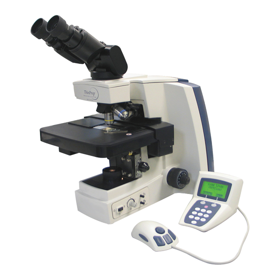
® Prep Pap Test slides that have been imaged by a ThinPrep Image Processor. The microscope uses stan- dard microscope optics enhanced with automated features that facilitate review of the slide. The CT views the slide and by means of automatic stage movement, is presented with fields of view containing objects of interest identified by the Imaging System. - Page 33 NTRODUCTION Figure 1-1 Review Scope Review Scope Operator’s Manual...
- Page 34 NTRODUCTION ThinPrep ® Imaging System: Laboratory Flow Figure 1-2 Lab Flow Review Scope Operator’s Manual...
-
Page 35: Section B: The Thinprep ® Imaging System Process
A slide ID reader scans the slide accession ID and then the Imaging Station scans the entire ThinPrep cell spot. The system identifies objects of interest found on the slide, based on integrated optical den- sity. - Page 36 NTRODUCTION Figure 1-3 ThinPrep ® Imaging Process Review Scope Operator’s Manual...
- Page 37 PreservCyt Solution sample vial. The sample is then capped, labeled, and sent to a labo- ratory equipped with a ThinPrep Processor. The samples are processed on ThinPrep Imaging System slides. After being processed, the slides are stained with ThinPrep Stain.
- Page 38 Lamp On/Off Switch Lamp Intensity Adjustment Lens Intensity Adjustments Note: Certain models of the ThinPrep Review Scope (model numbers 70669-001, 70669-002, and 70669-003) require a different pen and special setup instructions. See "MENU OPTION 3 SETUP MARKER" on page 4.6.
- Page 39 NTRODUCTION Dimensions 23” (584 mm) Deep 21” (533 mm) High 12” (304 mm) Wide Approximate Weight: 38 lbs (17.24 kg) Figure 1-5 Review Scope Dimensions 4” (101 mm) Rear 27” (610 mm) Deep 32” (813 mm) Wide 12” (305 mm) Wide Figure 1-6 Recommended Clearances Review Scope Operator’s Manual...
- Page 40 NTRODUCTION Console (Display and Keypad) 5.5” (140 mm) 5-Button Pod 4-Button Pod Note: (only one pod is used) 3” (76 mm) 4” 7” (102 mm) (178 mm) 4.75” 1.5” (121 mm) (38 mm) 3” (76 mm) 1” (25 mm) Approximate Weight: Approximate Weight: Approximate Weight: 4.3 oz (122g)
- Page 41 ThinPrep Microscope Slide for Use with the Imaging System The ThinPrep microscope slide is used by the ThinPrep Processor in preparing the patient slide. The slide utilizes fiducial marks, or fixed reference points, which are permanently printed features on the slide that are used to register the slide position on the stage.
- Page 42 NTRODUCTION Category II. The ThinPrep Review Scope is for indoor use only in an office or a clean laboratory envi- ronment. Altitude: 0 meters (sea level) to 2000 meters Atmospheric Pressure: 1100 millibar to 500 millibar Power Voltage: 100-120 / 200-240~ (Volts alternating current, no selection required) Mains supply voltage not to exceed ±...
- Page 43 4.3 oz (122 g) Review Scope Standards ® The ThinPrep Review Scope has been tested and certified by a U.S. nationally recognized testing Laboratory (NRTL) to comply with current Safety, Electro-Magnetic Interference (EMI) and Elec- tro-Magnetic Compatibility (EMC) standards. Refer to the product label, located on the rear of the instrument, to see the safety certification markings.
- Page 44 Auto Review session. The operator is alerted to any malfunction via a message on the console dis- play. If the system does not function, or there are persistent errors, contact Hologic Technical Support. (Refer to Service Information, Chapter 8.) SECTION REVIEW SCOPE HAZARDS The Review Scope is intended to be operated in the manner specified in this manual.
- Page 45 NTRODUCTION Symbols Used on the Instrument The following is an explanation of the symbols that may appear on your product: Symbol Title Description Standard information Caution Indicates the need for the user ISO 15223-1 Medical to consult the instructions for devices—Symbols to be used use for important cautionary with medical device labeling...
- Page 46 NTRODUCTION Symbol Title Description Standard information Caution, hot surface To indicate that the marked IEC 60417 Graphical symbols item can be hot and should not for use on equipment, symbol be touched without taking care 5041 Caution, risk of To identify equipment that has IEC 60417 Graphical symbols electric shock risk of electric shock...
- Page 47 NTRODUCTION Location of Labels on the Instrument ® ThinPrep Imaging System Review Scope 90-264V~ 4A 47-63 Hz 2 X T6.3AL 250V 5x20 mm CYTYC corporation 85 Swanson Road Boxborough, MA 01719 Model/Rating Label Serial Number Label Part Number Label WEEE Label...
- Page 48 Warnings Used in this Manual: WARNING Service Installation Only ® This instrument is to be installed by trained Hologic personnel only. WARNING Instrument Fusing For continued protection against fire, replace only with fuses of the specified type and current rating.
-
Page 49: Section G: Disposal
Instrument fuses. No special instructions; used fuses may be disposed of in your laboratory refuse. Disposal of the Device Please contact Hologic Service (refer to Service Information, Chapter 8). Do not dispose in municipal waste. Please contact Hologic Technical Support. -
Page 51: Section A: General
SECTION PREPARATION PRIOR TO INSTALLATION Pre-Installation Site Assessment A pre-installation site assessment is performed by Hologic Service Personnel. Be sure to have pre- pared any and all site configuration requirements as instructed by the Service personnel. Location And Configuration Review Scopes connected to the Server may be local or up to 200 meters (656 feet) away. Room for the console and Navigator Pod that accompany each review scope should be accommodated, as well as a comfortable amount of desk space for placing slide cassettes, flats or other slide containers. -
Page 52: Section D: Moving The Review Scope
If the Review Scope is to be shipped to a new location, please contact Hologic Technical Support. (Refer to Service Information, Chapter 8.) CAUTION: Do not lift or handle the Review Scope by the stage. -
Page 53: Section E: Connecting Review Scope Components
The console connection is used to interface the console and pod to the Review Scope. The operator interfaces with the Review Scope via these peripheral devices. • The service port (refer to Figure 2-3) is to be used only by trained Hologic personnel for ser- vice and diagnostic purposes. Review Scope Operator’s Manual... - Page 54 NSTALLATION Network connection Fusing Interconnection to RS Console (Bottom - Service Port for Hologic use only) Power Cord Figure 2-3 Review Scope, Rear Console Contrast Adjustment Knob (Turn the knob to adjust the contrast of the console display.) Interconnection Cable to Navigator Pod...
- Page 55 The Review Scope is supplied with a standard, tilting binocular head. (Refer to Figure 2-5.) Hologic has evaluated the use of an optional riser and an optional telescoping binocular head with the Review Scope. The specific riser and head that may be used are listed in Table 9.1. Contact Hologic Technical Support for more information on the installation of these items.
- Page 56 Figure 2-6 Sharpie Marking Pen The marking pen for the other models of the ThinPrep Review Scope is a Pilot Extra Fine Point mark- ing pen. Only use this specified marker for ThinPrep Review Scope model numbers 70669-001, 70669-002, and 70669-003. (Refer to Figure 2-7.) Figure 2-7 Pilot Marking Pen The marking pen must be present for physical marking of the slide at the conclusion of a review.
-
Page 57: Section F: Power On The Review Scope
NSTALLATION Figure 2-8 Focus Knob Covers SECTION POWER ON THE REVIEW SCOPE The Review Scope power On/Off switch is located at the rear of the microscope. Confirm that it is in the Off position and plug the receptacle end of the power cord into the socket. Plug the other end of the power cord into a wall outlet. - Page 58 NSTALLATION Power On LED Figure 2-9 Power Entry Module and On/Off Switch Allow the microscope to initialize. The instrument is ready for operation when the display on the console shows Enter Login ID [Offline]. (Refer to Figure 2-10.) Soft keys (software definable) will implement user selections or actions, associated with the labels on the display directly above the...
- Page 59 NSTALLATION NEXT PREVIOUS OBJECTIVE (10X / 40X) NEXT MARK PREVIOUS MARK OBJECTIVE JOYSTICK (10X / 40X) JOYSTICK both sides 4-BUTTON POD 5-BUTTON POD Note: Only one pod is used. Mark used to electronically mark or unmark cells for dotting by the marking pen Joystick used for directional and velocity control of the motorized stage during slide review used to increase or decrease stage speed during autoscan...
-
Page 60: Section G: Storage And Handling - Post Installation
NSTALLATION Condenser (Aperture) Adjustment Thumbscrews Condenser (Aperture) Focus Focus Knob (on Knob left & right sides, both) Lamp On/Off Fine Focus Coarse Focus Lamp Intensity Adjustment White & Green Mark Indicator Intensity Adjustments Figure 2-12 Illumination Control Panel SECTION STORAGE AND HANDLING - POST INSTALLATION The Review Scope may be stored in the location where it was installed. - Page 62 ® ThinPrep Pap Test cervical cytology sample slides processed by the ThinPrep Imaging System are reviewed at the Review Scope (RS). Slide review by a cytotechnologist is assisted by automated fea- tures. (Refer to Figure 3-1 for typical slide review process.)
- Page 63 PERATION OF THE EVIEW COPE Manual Review Manual Review refers to a slide review in which • patient slide data is not retrieved from or communicated to the server • a scan of the entire cell spot is conducted by the operator initiating each movement of the stage •...
- Page 64 For less than an 8-hour workday, the following formula must be applied to determine the maximum number of slides to be reviewed during that workday: Number of hours examining slides X 100 The ThinPrep Imaging System limit of 100 slides in an 8-hour workday includes the following: • Screening 22 Fields of View •...
- Page 65 PERATION OF THE EVIEW COPE (Auto Review Mode) Power On User Login Autoscan Overlap (choose) (Manual Review Mode) Mark Indicator (on/off) Online Offline Register Slide Calibrate (4-button pod) Joystick (Daily) Manual Scan Calibrate Marker (Daily) Review Marked Fields (Optional) Load Slide (if negative) Mark Slide Register Slide...
- Page 66 Ultra Fine Point marking pen or a Pilot Extra Fine point marking pen is used for physi- cally marking the slides, depending on the model of ThinPrep Review Scope you have. If a pen is not already installed, refer to instructions on page 4.6 for installing the pen. (A box of pens is provided at instrument installation.)
- Page 67 The preferences are downloaded from the Server to any RS the CT logs onto. (Refer to setting preferences on page 4.13.) Note: See your lab administrator for any issues regarding Login ID’s. Also, refer to the ThinPrep Image Processor’s Operator’s Manual. Scan Overlap An autoscan overlap must be selected.
- Page 68 (Refer to Figure 3-2‚ Loading a Slide.) CAUTION: Inspect the slide before loading. ® Confirm it is a clean, properly labeled ThinPrep Pap Test slide. Check for any damage. Do not load a slide onto the stage upside down.
- Page 69 PERATION OF THE EVIEW COPE AUTO REVIEW (continued) Slide Clamp Arm Slide Orientation: Frosted Side Up, Label to the Left Figure 3-2 Loading a Slide Press the Next button on the pod. A flash of red light and a beep will indicate that the slide accession ID has been scanned.
- Page 70 PERATION OF THE EVIEW COPE AUTO REVIEW (continued) Illuminated Slide Fiducial Mark Mark Indicator Poor Alignment: Poor Alignment: Good Alignment Fiducial Mark is too far Fiducial Mark is on away from Illuminated top of Illuminated Mark Indicator Mark Indicator Figure 3-3 Align the Fiducial Mark and the Mark Indicator When the fiducial mark is aligned with the mark indicator, press the Next button on the pod.
- Page 71 22 fields of view. This is done by counting the cells presented in each ® of the 22 fields of view presented by the ThinPrep Imaging System. The chart below lists the requirements for the average number of cells in each field dependent upon the microscope objective...
- Page 72 PERATION OF THE EVIEW COPE AUTO REVIEW (continued) To proceed to the next field of view, press the Next button on the pod. Press the Prev button on the pod to go back to the previous field of view (unless you are at the first one). If the objective is at 40X when the Next or Prev button is pressed, the objective will automatically return to 10X before pro- ceeding.
- Page 73 PERATION OF THE EVIEW COPE AUTO REVIEW (continued) To estimate the cellularity of the preparation in scantly cellular specimens, a specimen adequacy check can be also performed. In accordance with Bethesda 2001 criteria , a minimum of 10 fields should be counted along a diameter of the cell spot that includes the center. Dependent upon the microscope objective used, use the chart below and count the average number of cells in each field.
- Page 74 PERATION OF THE EVIEW COPE AUTO REVIEW (continued) Slide Scanning CAUTION: Autoscan must be done if any electronic marks have been made. The slide may be scanned whether any electronic marks have been made or not. If any electronic marks have been made, the entire slide must be scanned. The Review Scope has an Autoscan func- tion, enabling scan coverage of the entire cell spot.
- Page 75 PERATION OF THE EVIEW COPE AUTO REVIEW (continued) • Press the Next button on the pod to resume scanning (from the location where the scan left off) An audible beep indicates the completion of scanning. The display shows Scan Paused, 100% Com- plete.
- Page 76 PERATION OF THE EVIEW COPE AUTO REVIEW (continued) Check the Slide Registration If all of the physical marks have been accepted, the stage positions the slide to show the first fiducial mark. The slide registration is checked to confirm that there has been no slide movement or loss of stage position during slide review.
- Page 77 PERATION OF THE EVIEW COPE An audible beep indicates the mark has been created. The display indicates slide review is complete. The slide may be removed from the slide holder. The Load Slide screen is displayed and the Review Scope is ready for another slide review. Load Slide Review Complete Press Next...
- Page 78 PERATION OF THE EVIEW COPE SUBSEQUENT REVIEW (continued) Autolocate - same as Auto Review. Notice that the soft keys are Review and Finish. Autolocate 4 of 22 Press Next/Prev Review Finish Because the entire slide has been screened previously [at least once], you may skip to review or finish at any time.
- Page 79 COPE SECTION MANUAL SLIDE REVIEW ThinPrep slides may be manually reviewed and marked at the Review Scope. Manual Review is always an available option. It will be required in certain conditions, which include: • Slide not imaged (the slide has not been imaged by the Image Processor) •...
- Page 80 With Indicator Press Next ® Manual Review cannot make use of the fiducial marks that are printed on the ThinPrep Microscope Slides. In order to create a reference coordinate for physically dotting the slide at the end of review, the operator must align two edges of the cell spot with the mark indicator.
- Page 81 PERATION OF THE EVIEW COPE MANUAL REVIEW (continued) Align 1st Align 2nd Align the cell spot ‘edge’ with the mark indicator. View 1st Alignment View 2nd Alignment Figure 3-4 Align Cell Spot Press the Next button on the pod when satisfied with the second alignment. Manual Scan/Review of the Cell Spot Scan Paused 0% Complete...
- Page 82 PERATION OF THE EVIEW COPE MANUAL REVIEW (continued) Scan Paused ‘Review’ soft key 29% Complete appears the first time you electronically Press Next/Prev. mark. Reset Review The operator may: • Press the Next button on the pod to move to the next location •...
- Page 83 PERATION OF THE EVIEW COPE MANUAL REVIEW (continued) When the physical marks have been made, they are presented for final approval. This is to ensure that the physical marks coincide with the electronic marks. Mark Verify 1 of 3 Press Next Reject Good Poor...
- Page 84 PERATION OF THE EVIEW COPE MANUAL REVIEW (continued) Slide Review Cancelled Continue When the cell spot alignment has been confirmed, the stage positions the slide to receive the Slide Reviewed Mark. The marker pen is uncapped and a small double line is marked on the coverslip, located on the bottom arc of the slide.
- Page 85 PERATION OF THE EVIEW COPE SECTION SHUTTING DOWN THE REVIEW SCOPE Normal Shut Down When you are finished screening slides, the Review Scope may be shut off. Make sure there are no slides left on the stage. Turn off the illuminator lamp switch. Turn off the Review Scope power switch.
- Page 87 PERATION OF THE OFTWARE C h a p t e r F o u r Operation of the Software Menu SECTION INTRODUCTION A User accessible software menu is available for calibration of the Review Scope components and to select user preferences. Refer to Figure 4-1‚ Review Scope On-line Menus. User input is via the keys on the console keypad and the joystick and buttons on the pod.
- Page 88 PERATION OF THE OFTWARE 1 Left/Right 2 Up/Down 1 Continuous 2 Auto ST/SP 3 Manual ST/SP 1 Min Overlap Menu Preferences 2 Medium Overlap 3 Max Overlap 1 Logout / Login 1 Scan Dir. 2 Joystick Cal. 2 Scan Type 3 Setup Marker 3 Scan Overlap Autolo.
-
Page 89: Section B: Menu Option 1 Login/Logout
PERATION OF THE OFTWARE SECTION MENU OPTION 1 LOGIN/LOGOUT If the RS is offline (not communicating with the server), the menu option reads Login; if the RS is online, the menu option reads Logout. Login is used to enter the three-digit operator ID at the start of a screening session at the review scope. -
Page 90: Section C: Menu Option 2 Joystick Calibration
PERATION OF THE OFTWARE Enter Login ID Offline The Enter Login ID display will appear if logout was successful. If the user does not wish to logout, press the No soft key on the console. The software will display the Load Slide screen. - Page 91 Press the Continue soft key on the key pad to return to the Load Slide screen. Joystick Cal. Failed Continue If calibration fails, retry it several times. If calibration continues to fail, contact Hologic Technical Support. Review Scope Operator’s Manual...
-
Page 92: Section Dmenu Option 3 Setup Marker
2 Marker Cal. Back A prompt to load a blank slide appears. Load Blank Slide Press Next Load a blank ThinPrep slide into the slide holder on the stage. Press the Next button on the pod. Review Scope Operator’s Manual... - Page 93 Load the pen into the holder. • For ThinPrep Review Scopes that use the Sharpie marking pen, push the pen into the guide, making sure it is seated against the holder. Then press the locking arm to the right until it firmly grips the pen.
- Page 94 Every time a new marker is installed • After a mark is rejected while verifying marks Note: The object marker on ThinPrep Review Scope model numbers 70575-001, 70575-003, 71062- ® 001, and 71062-002 uses an ultra fine tip Sharpie marking pen. The object marker on ThinPrep Review Scope model numbers 70669-001, 70669-002, and 70669-003 uses a Pilot extra fine marking pen.
- Page 95 Load the pen into the holder. • For ThinPrep Review Scopes that use the Sharpie marking pen, push the pen into the guide, making sure it is seated against the holder. Then press the locking arm to the right until it firmly grips the pen.
- Page 96 Object Marker Pen • For ThinPrep Review Scopes that use the Pilot marking pen, push the pen into the guide. Loosen your hold on the pen and notice that it moves up slightly. Gently hold the pen there and press the locking arm to the right until it firmly grips the pen. Because the pen is thinner than the holder, it may be helpful to hold the pen at a 15°...
- Page 97 From the menu, select option 3, Setup Marker, and then select option 2, Marker Cal. Load Blank Slide Press Next ® Load a blank ThinPrep microscope slide into the slide holder on the stage. Press the Next button on the pod. Review Scope Operator’s Manual...
- Page 98 PERATION OF THE OFTWARE Focus Marker Cal. Focus Continue Figure 4-8 Focus on the Painted Arc Looking through the eyepieces, focus the microscope on the top arc of the frosted area. (Refer to Fig- ure 4-8.) Press the Continue soft key when ready. Slide a lint-free wipe between the pen tip and the slide Slide a lint-free wipe under the pen tip.
-
Page 99: Section Emenu Option 4 Preferences
PERATION OF THE OFTWARE SECTION MENU OPTION 4 PREFERENCES Preferences allows the setting of user preferences including Autoscan settings and maximum speed for Autolocate. For each user-selectable preference, the console display shows the current setting of the parameter. Use the pod buttons to change the setting to the desired value. The setting is stored locally (in RS memory) until the user preferences are updated on the Server during user Logout. - Page 100 PERATION OF THE OFTWARE Preferences 2 Scan Type The autoscan function presents the entire cell spot in a defined path at 10X magnification. Three types of scan motion are selectable: • Automatic Continuous - Scan motion is initiated by the RS and consists of steady movement across the cellular region, with each pass overlapping the previous scan.
- Page 101 PERATION OF THE OFTWARE Continuous Scan Continuous 2 Auto ST/SP 3 Manual ST/SP Save A list of the scan motion options is displayed. To select Continuous Scan, press 1 on the console key- pad and then press the Save soft key. For this preference, a scan speed setting will be adjusted and ⊗...
- Page 102 PERATION OF THE OFTWARE Auto Start-Stop Scan 1 Continuous Auto ST/SP 3 Manual ST/SP Save To select Auto Start-Stop Scan, press 2 on the console keypad and then press the Save soft key. For this preference, a scan speed setting (the speed of the stage moving from field of view to field of ⊗...
- Page 103 PERATION OF THE OFTWARE Pause Duration Next Button Prev Button => <= <= => Faster scan Slower scan Test Save (shorter pause) (longer pause) Similar to the speed setting display, use the Next button on the pod to decrease the length of the pause and use the Prev button to increase the length of the pause.
- Page 104 PERATION OF THE OFTWARE Manual Start-Stop Scan 1 Continuous 2 Auto ST/SP Manual ST/SP Save To select Manual Start-Stop Scan, press 3 on the console keypad. For this preference, there are no set- tings to adjust, as starting and stopping of the scan is manual, by pressing the Next button on the pod.
- Page 105 PERATION OF THE OFTWARE Scan Overlap Preference Test Press Next Look through the eyepieces to observe the field of view overlap as the cell spot is scanned. Press the Next button on the pod to return to the Scan Overlap menu. Select a different overlap setting if desired, or press the Save soft key to save the setting.
- Page 106 PERATION OF THE OFTWARE Autolocate Test Press Next Finish An Autolocate Test display appears. Look through the eyepieces and repeatedly press the Next but- ton on the pod to observe the speed of the stage motion. Press the Finish soft key return to the auto- locate speed setting display.
- Page 107 PERATION OF THE OFTWARE Preferences 5 Joystick Setup The joystick setup selects the frame of reference on which the slide movement is based and then sets ⊗ the speed of movement. From the preferences menu, select 5, Joystick Setup. Press the cancel key at any time to exit out of menus.
- Page 108 PERATION OF THE OFTWARE Speed Setting Prev Button Next Button <= <= => => Test Save The speed setting display shows a highlighted bar with the current speed setting (default is 50). Press the Next button on the pod to increase the speed value. Press the Prev button on the pod to decrease the speed value.
- Page 109 PERATION OF THE OFTWARE Preferences 6 Beep Volume The volume of the audible beep may be increased or decreased. From the preferences menu, select 6, ⊗ Beep Volume. Press the cancel key at any time to exit out of menus. Beep Volume Prev Button Next Button...
- Page 110 PERATION OF THE OFTWARE Preferences 7 Button Setup The function buttons on the pod may be reassigned to fit user preference. From the preference menu, ⊗ select 7, Button Setup. Press the cancel key at any time to exit out of menus. Refer to Figure 4-10 for defaults.
- Page 111 PERATION OF THE OFTWARE Select Prev [Next] The Next button position is shown on the display. Select the location for the Previous button. Press the actual button on the pod that will be assigned as the Previous button. Button Setup Obj.
- Page 112 PERATION OF THE OFTWARE Preferences 8 Reset Defaults Preferences associated with the active user ID may be restored to the factory default settings, if desired. All settings will return to the default configuration. From the preferences menu, select 8, Reset Defaults. The default values for the parameters that may change are restored.
-
Page 113: Section F: Menu Option 5 Open Error Log
PERATION OF THE OFTWARE SECTION MENU OPTION 5 OPEN ERROR LOG The Review Scope logs the last 100 errors encountered, beginning with the most recent. This display allows the user to view and scroll through the list of errors. Displayed are the log sequence, the error number, the date and time the error was logged. -
Page 114: Section Gmenu Option 6 Usage Count
PERATION OF THE OFTWARE SECTION MENU OPTION 6 USAGE COUNT The Review Scope counts the number of slide reviews performed on each microscope. The Usage Count display shows the number of reviews. From the menu, select 6, Usage Count. Slides Reviewed Continue To close the display, press the Continue soft key. -
Page 115: Thinprep Review Scope Preferences Worksheet
® ThinPrep Review Scope Preferences Name: ________________________ Date: __________ 1 Scan Direction Left to Right Up and Down 2 Scan Type Trial #1 Trial #2 Trial #3 Final Setting Continuous Speed ____________ Auto Start/Stop Speed ____________ Pause ____________ Manual Start/Stop... - Page 116 Button Setup on the Navigator Pod N = Next P = Previous Objective M = Mark Next (10X/40X) O = Objective Mark Previous Joystick Joystick Joystick Trial Settings Final Settings Default Settings Next N = Next Previous P = Previous M = Mark O = Objective Mark...
-
Page 118: Chapter Five
Review Scope Maintenance The instrument must be maintained regularly in order to ensure reliable performance. Perform maintenance on the instrument as described in this section. The instrument requires supplemental preventive maintenance annually by Hologic service personnel. SECTION DAILY JOYSTICK CALIBRATION 4-button pod: calibration is recommended once daily or at the start of each shift. -
Page 119: Section C: Replacing The Illuminator Light Bulb
EVIEW COPE AINTENANCE not drip the cleaning agent on painted surfaces or plastic.) Remove any glass dust from these areas. (Refer to Figure 5-1.) Slide Present Slide Registration Sensor Edges Top Surface of Stage Figure 5-1 Slide Present Sensor SECTION REPLACING THE ILLUMINATOR LIGHT BULB Refer to Ordering Information for replacement light bulbs. - Page 120 Console (Bottom - Service Port for Power Cord Hologic use only) Figure 5-2 Rear of Microscope CAUTION: Do not grasp the microscope by the stage or the optics. Do not rest the stage against your body as this may misalign the stage.
- Page 121 EVIEW COPE AINTENANCE Loosen This Lamp Bracket Screw Thumb Screws White Wires Figure 5-4 Illuminator Assembly Access and Lamp Bracket WARNING: Hot Surfaces Glass Note: Observe the orientation of the lamp bracket assembly before removing it. The white wires should come out from the top of the assembly. 6.
-
Page 122: Section Dreplacing The Fuses
EVIEW COPE AINTENANCE 8. Return the lamp fixture to the holding bracket, seating it flat against the bracket. Tighten the thumb screws. Confirm that the wires come out from the top of the fixture (Refer to Figure 5-4). Be sure the wires are not pinched when the thumb screws are tightened. 9. - Page 123 EVIEW COPE AINTENANCE Fuse Holder Figure 5-7 Remove the Fuse Holder 7. Note the position of the fuses in the holder, so that the new fuses will be inserted the same way. 8. Remove the existing fuses and discard them. 9.
- Page 124 12. Plug the power cord into the socket on the microscope. 13. Reattach the power cord to the wall outlet. 14. Turn on the microscope. 15. If the microscope still fails to operate, contact Hologic Technical Support. Review Scope Operator’s Manual...
-
Page 125: Section Ekoehler Alignment
EVIEW COPE AINTENANCE SECTION KOEHLER ALIGNMENT Koehler illumination provides uniform, bright illumination across the entire field of view, with mini- mal glare. Alignment of the light path may be done as needed. 1. Load a slide with cells on it into the slide holder. Bring the specimen into focus at 10X. 2. - Page 126 Review Scope Maintenance for the Month page 5.1 Reference: page 5.1 page 5.1 Chapter Five EVIEW COPE AINTENANCE Monthly or As Frequency: DAILY DAILY As Needed Needed Joystick Calibration Marker Calibration General Cleaning Replacement of light bulb/fuse (4-button pod only) This page intentionally left blank.
- Page 127 EVIEW COPE AINTENANCE This page intentionally left blank. 5.10 Review Scope Operator’s Manual...
-
Page 129: Chapter Six
ID camera and the slide. Slide ID misprint. • Manually enter the slide ID via the keypad (if OCR Slide ID reader malfunction. format). If the message persists, contact Hologic Technical Support. Cell Spot Alignment Error During Manual Review mode, the edge of the •... - Page 130 Network connection cannot be made. Cabling Check that the network cable is securely plugged not connected. into the rear of the Review Scope. If the error persists, contact Hologic Technical Sup- port. Imaging Not Successful The Image Processor attempted to image the Perform a manual review of the slide.
- Page 131 • Confirm that all cable connections to the RS and the IPC are secure. • If the error persists, contact Hologic Technical Support. Slide Not Found The slide ID is not in the database.
-
Page 132: Section B: User-Correctable Errors
Check that cable connections are secure and safely routed to avoid being pinched, pulled out, tripped over, etc. Turn the power switch to the On position. If user-correctable errors persist, contact Hologic Technical Support. Review Scope Operator’s Manual... - Page 133 ROUBLESHOOTING Table 6.2 lists the text messages that may be displayed for a user-correctable error. Restart the Review Scope as prompted. Table 6.2: User-Correctable System Errors Error Error Text Corrective Action 7020 Moving Nosepiece Check for physical interference of nosepiece. Check for proper seating of objectives.
- Page 134 ROUBLESHOOTING Table 6.2: User-Correctable System Errors 7091 Toggling Nosepiece Check for physical interference of nosepiece. Check for proper seating of objectives. Lower the stage with the coarse focus knob. Power cycle the RS. 7092 Serial Number Power cycle the RS. If the problem is not resolved, contact Technical Support.
- Page 135 ROUBLESHOOTING Table 6.2: User-Correctable System Errors 7153 Readying Pen Check for pen obstruction. Power cycle the Review Scope to see if the error clears. Perform marker calibration (menu option 3). 7154 Moving Stage Check for physical interference of nosepiece. Check for proper seating of objectives. 7155 Lower the stage with the coarse focus knob.
- Page 136 ROUBLESHOOTING Table 6.2: User-Correctable System Errors 7198 Capping Pen Check for pen obstruction. Power cycle the Review Scope to see if the error clears. Perform marker calibration (menu option 3). 7200 Moving Nosepiece Check for physical interference of nosepiece. Check for proper seating of objectives. Lower the stage with the coarse focus knob.
- Page 137 ROUBLESHOOTING Table 6.2: User-Correctable System Errors 7222 Moving Nosepiece Check for physical interference of nosepiece. Check for proper seating of objectives. 7223 Lower the stage with the coarse focus knob. Power cycle the RS. 7224 Moving Stage Check for physical interference of nosepiece. Check for proper seating of objectives.
- Page 138 ROUBLESHOOTING Table 6.2: User-Correctable System Errors 7245 Moving Nosepiece Check for physical interference of nosepiece. Check for proper seating of objectives. Lower the stage with the coarse focus knob. Power cycle the RS. 7246 Moving Stage Check for physical interference of nosepiece. Check for proper seating of objectives.
- Page 139 ROUBLESHOOTING Table 6.2: User-Correctable System Errors 7286 Moving Stage Check for physical interference of nosepiece. Check for proper seating of objectives. Lower the stage with the coarse focus knob. Power cycle the RS. 7287 Readying Pen Check for pen obstruction. Power cycle the Review Scope to see if the error clears.
- Page 140 ROUBLESHOOTING Table 6.2: User-Correctable System Errors 7452 Moving Scan Position X Check for interferences and remove any obstructions. Power cycle the RS. 7453 Move to 40X Check for physical interference of nosepiece. Lower the stage with the coarse focus knob. 7454 Move to 10X Power cycle the RS.
-
Page 141: Section C: Recoverable System Errors
ROUBLESHOOTING SECTION RECOVERABLE SYSTEM ERRORS These are errors from which the system automatically recovers. Review Scope operation continues uninterrupted. No message is signaled to the operator. The errors are logged in the Error Log and may be viewed from the console display or at the user interface at the Image Processor. No operator action is required. - Page 142 ROUBLESHOOTING “Server Communication Error” or “Error Initializing Network” occurs at power up or while reviewing slides. • Communication between the Review Scope and Server has been interrupted. Check if the server is turned on. • Check that the network cables from the server to the hubs and the hubs to the RS are securely connected.
-
Page 144: Chapter Seven
Cassette The container that holds slides for batch processing. Each cassette may hold up to 25 slides. Cell Spot ® The area within the pre-printed arcs on a ThinPrep Microscope Slide that contains the patient’s cells. Collector Iris Diaphragm Also known as the field diaphragm or field stop. Controls the size (diameter) of the column of light emitting from the collector. - Page 145 Review Scope stage at the beginning and end of slide review. Field of View. A circular area of the slide, as viewed through the microscope. Image Processor. The components of the ThinPrep Imaging System including the Imaging Station, the Image Processor Controller, the Server and the User Interface.
- Page 146 EFINITIONS AND BBREVIATIONS Joystick The round control in the center of the pod, used to move the microscope stage or set its speed while viewing cells through the microscope. Koehler Illumination A microscope alignment technique that establishes optimal lens positions and iris diaphragm sizes with respect to the specimen plane and objective field of view to provide bright, even illumination of the specimen.
- Page 147 RS. Review Scope. Site ® The set of coordinates (as referenced from the fiducial marks on the ThinPrep microscope slide) that centers the area to be reviewed within the field of view. Slide Data Record The data associated with a specific accession ID/slide.
- Page 148 RS. ® A slide that has undergone Auto review has the mark placed on the top arc of the ThinPrep slide. A slide that has undergone Manual review has the mark placed on the bottom arc of the ThinPrep slide.
- Page 149 EFINITIONS AND BBREVIATIONS Verification Slide This is a special slide that has custom features that allow for periodic system verification. Review Scope Operator’s Manual...
-
Page 151: Chapter Eight
Orders can also be faxed to the attention of Customer Service at 508-229-2795. Warranty A copy of Hologic’s limited warranty and other terms and conditions of sale may be obtained by contacting Customer Service at the numbers listed above. Technical Support ®... - Page 152 ERVICE NFORMATION This page intentionally left blank. Review Scope Operator’s Manual...
-
Page 154: Chapter Nine
Orders can also be faxed to the attention of Customer Service at 508-229-2795. Warranty A copy of Hologic’s limited warranty and other terms and conditions of sale may be obtained by contacting Customer Service at the numbers listed above. Protocol for Returned Goods ®... - Page 155 Additional filter for collector lens 04322-001 Focus Knob Covers Covers for fine focus knobs 2 ea 04815-001 Review Scope Operator’s Additional Operator’s Manual MAN-03352-001 Manual Telescoping Head Option for tilting head binoculars 52029-001 Riser Hologic riser ASY-03268 Review Scope Operator’s Manual...
- Page 157 NDEX Index Accessing Manual Mode 3.18 Align Cell Spot 3.19 Auto Review 3.1, Auto Start-Stop Scan 4.16 Autolocate 3.10, 4.19 autolocate speed 4.19 Automatic Continuous 4.14 Automatic Start Stop 4.14 Autoscan overlap 4.18 Bad OCR Read Beep Volume 4.23 Binocular Head Button Setup 4.24 Cancel console key...
- Page 158 NDEX Daily Screening Rates Data Error Dimensions and Weight 1.12 Disposal 1.18 Environmental 1.10 Error Log 4.27 Errors Eyepieces 2.5, Finish soft key 3.14 Focus knob covers Fuse 5.5, General Cleaning Halogen light bulb Hazards 1.13 Index.2 Review Scope Operator’s Manual...
- Page 159 NDEX Illumination Control Panel 2.10 Imaging Not Successful Imaging Slide 6.11 Incorrect Software Version Installation Internal Quality Control 1.13 Invalid Login Invalid Slide ID Joystick Joystick Cal. Failed 4.5, Joystick Calibration 4.4, Joystick Setup 4.21 Koehler alignment Koehler illumination Lightbulb Load Test Slide, Press Next Login Login ID...
- Page 160 NDEX Manual Review 3.2, 3.18 Manual Scan 3.20 Manual Slide Review 3.18 Manual soft key 3.19 Manual Start Stop 4.14 Manual Start-Stop Scan 4.18 Mark button 2.9, 3.10, 3.21, 4.25 mark indicator on/off 3.7, 4.20 Marker Calibration Marking pen 2.6, 4.7, material safety data sheet CytoLyt Solution...
- Page 161 NDEX Physical Marking of the Slide 3.14, 3.21 1.9, 1.12, 2.8, 4.26, Power 1.11 Power On 1.13 Preferences 4.13 Previous button 2.8, 3.10, 3.21, 4.25 Prime the marker 4.7, prime the object marker 4.11 Protective Temperature Coefficient Devices 1.11 Recoverable System Errors 6.13 Register the Slide Fiducial Marks Reject soft key...
- Page 162 NDEX Slide Cassette slide labeling formats 1.10 Slide Not Found Slide Removed Slide Review Cancelled Slide Reviewed Mark 3.15, 3.23 Slide Scanning 3.13 Soft keys Specimen Adequacy 3.10, 3.12 specimen adequacy 3.10 Subsequent Review 3.1, 3.16 Technical Specifications Technical Support Troubleshooting Usage Count 4.28...
Need help?
Do you have a question about the ThinPrep and is the answer not in the manual?
Questions and answers