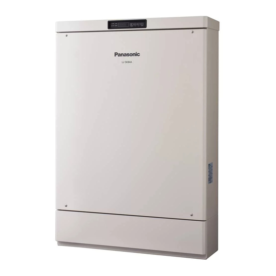
Panasonic LJ-SK56A Installation Manual
Lithium-ion storage battery system
Hide thumbs
Also See for LJ-SK56A:
- User manual (14 pages) ,
- Quick start manual (2 pages) ,
- User manual (32 pages)
Table of Contents
Advertisement
- Thank you for purchasing the Panasonic Lithium-ion storage battery system.
- Before installing the product, please read this manual carefully and follow all safety precautions at all times.
- After the installation, keep this manual and the User's Manual for future reference.
- Only qualified
persons with the appropriate skills are allowed to perform the tasks described in this manual.
- After the installation, use this manual to check that the product operates correctly. Also, use the User's Manual to
explain how to use and perform day to day operation of the product to the customer.
- If the product fails, even within the warranty period, due to non-conformance with the Installation Manual, the User's
Manual or the caution labels attached to the product, it will not be repaired free of charge.
- For disposal, please contact your Household Hazardous waste depot.
Installation Manual
Lithium-ion Storage Battery System
Table of Contents
Safety Precautions
Installation
1
Typical
System Configuration
2
Product Description ......................................12
3
Confirming Product Number
4
Mounting of System and Battery.................. 20
5
Electrical Connection of System and Battery .. 29
6
Mounting of Network Adaptor ...................... 40
7
Electrical Connection of Network Adaptor ... 43
Setup
1
Control Panel ............................................... 50
2
List of Commands in Work Setting Mode ... 52
3
Setting Procedures ...................................... 54
4
Checking Energization ................................. 55
5
Setting Date/Time ........................................ 57
6
Setting Parameters for Installer ................... 60
7
Setting Parameters for Grid Operator .......... 68
8
Test Run ...................................................... 93
9
Checking the Network Adaptor Connections .. 97
10 Complete Settings ....................................... 99
Model No. LJ-SK56A
Lithium-ion Battery
Model No. LJ-SBK01
Network Adaptor
Model No. LJ-NA02
........................ 7
........................ 17
Advertisement
Chapters
Table of Contents


Need help?
Do you have a question about the LJ-SK56A and is the answer not in the manual?
Questions and answers