Canon iR4570 Series Service Manual
Hide thumbs
Also See for iR4570 Series:
- Service manual (876 pages) ,
- User manual (84 pages) ,
- Printer manual (62 pages)
Table of Contents
Advertisement
Quick Links
Advertisement
Chapters
Table of Contents
Troubleshooting

Related Manuals for Canon iR4570 Series


Summary of Contents for Canon iR4570 Series
-
Page 1: Service Manual
Service Manual iR4570/3570, 2870/2270 Series Jan 31 2005... - Page 3 When changes occur in applicable products or in the contents of this manual, Canon will release technical information as the need arises. In the event of major changes in the contents of this manual over a long or short period, Canon will issue a new edition of this manual.
- Page 4 Introduction Symbols Used This documentation uses the following symbols to indicate special information: Symbol Description Indicates an item of a non-specific nature, possibly classified as Note, Caution, or Warning. Indicates an item requiring care to avoid electric shocks. Indicates an item requiring care to avoid combustion (fire). Indicates an item prohibiting disassembly to avoid electric shocks or problems.
- Page 5 Introduction The following rules apply throughout this Service Manual: 1. Each chapter contains sections explaining the purpose of specific functions and the relationship between electrical and mechanical systems with reference to the timing of operation. In the diagrams, represents the path of mechanical drive; where a signal name accompanies the symbol , the arrow indicates the direction of the electric signal.
-
Page 7: Table Of Contents
Contents Contents Chapter 1 Introduction 1.1 System Construction............................1- 1 1.1.1Overview of the System with a Delivery Accessory................... 1- 1 1.1.2Overview of System Construction (output accessories)................1- 1 1.1.3Delivery Accessory System Configuration 1 ....................1- 1 1.1.4Output Accessories System Configuration 1....................1- 3 1.1.5Delivery Accessory System Configuration 2 .................... - Page 8 Contents 1.2.3.13 Transmission/Reception Settings..................... 1- 54 1.2.3.14 Box Settings............................. 1- 56 1.2.3.15 Box Settings............................. 1- 57 1.2.3.16 Printer Settings..........................1- 57 1.2.3.17 Address Book Settings........................1- 58 1.2.4 Maintenance by the User........................... 1- 61 1.2.4.1 Cleaning ............................. 1- 61 1.2.4.2 Inspection............................1- 61 1.2.5 Safety.................................
- Page 9 Contents 2.6.1Points to Note ............................2- 27 2.6.2Checking the Contents..........................2- 27 2.6.3Installation Procedure..........................2- 28 2.6.4Installation in a NetSpot Accountant (NSA) Environment ............... 2- 32 2.7 Installing the NE Controller ..........................2- 33 2.7.1Installing the NE Controller-A1 ........................ 2- 33 Chapter 3 Basic Operation 3.1 Construction ..............................
- Page 10 Contents 4.6.8Flow of Image Data for the Fax Transmission Function ................4- 28 4.6.9Flow of Image Data for the Fax Reception Function ................4- 29 4.6.10Flow of Image Data for the Fax Reception Function ................4- 30 4.6.11Flow of Image Data for the PDL Function ....................4- 31 4.6.12Flow of Image Data for the PDL Function ....................
- Page 11 Contents 5.3.6 Image Processing ............................5- 22 5.3.6.1 Outline ............................... 5- 22 5.3.6.2 CCD Drive............................5- 23 5.3.6.3 Gain Correction and Offset Correction of the CCD Output.............. 5- 23 5.3.6.4 A/D Conversion of the CCD Output ....................5- 24 5.3.6.5 Shading Correction (outline) ......................5- 24 5.3.6.6 Shading Adjustment ..........................
- Page 12 Contents 6.1.1Specifications, Control Mechanism, and Functions ..................6- 1 6.1.2Major Components ............................6- 2 6.1.3Construction of the Control System ......................6- 2 6.2 Basic Sequence ..............................6- 6 6.2.1Basic Sequence ............................6- 6 6.3 Various Controls..............................6- 7 6.3.1 Controlling the Laser Activation Timing ....................6- 7 6.3.1.1 Turning On and off the Laser Light.....................
- Page 13 Contents 7.8.1Overview ..............................7- 16 7.8.2Route of Toner Supply ..........................7- 17 7.8.3Controlling the Drive of the Toner Cartridge.................... 7- 18 7.8.4Toner Supply Control ..........................7- 19 7.8.5Recovery Sequence ........................... 7- 19 7.8.6Toner Level Detection..........................7- 20 7.9 Transfer Unit ..............................7- 21 7.9.1 Outline of the Transfer Unit........................
- Page 14 Contents 7.12.4.1 Removing the Front Cover Unit ...................... 7- 40 7.12.4.2 Removing the Waste Toner Case..................... 7- 40 7.12.4.3 Removing the Toner Cartridge ......................7- 41 7.12.4.4 Removing the Drum Unit ........................ 7- 42 7.12.4.5 Removing the Developing Assembly ....................7- 43 7.12.4.6 Removing the Upper Tray .......................
- Page 15 Contents 7.12.10.12 Removing the Toner Feedscrew Motor..................7- 71 7.12.11 Static Charge Eliminator........................7- 71 7.12.11.1 Removing the Static Eliminator ....................7- 71 Chapter 8 Pickup/Feeding System 8.1 Construction ..............................8- 1 8.1.1Specifications, Controls, and Functions ...................... 8- 1 8.1.2Specifications, Controls, and Functions ...................... 8- 2 8.1.3Division into Blocks ............................
- Page 16 Contents 8.5.4Paper Retaining Mechanism ........................8- 43 8.6 Registration Unit.............................. 8- 45 8.6.1Overview..............................8- 45 8.6.2Checking Horizontal Registration ......................8- 45 8.7 Duplex Feeding Unit............................8- 47 8.7.1Overview..............................8- 47 8.7.2Overview..............................8- 48 8.7.3Sequence of Image Formation ........................8- 49 8.7.4Sequence of Image Formation ........................
- Page 17 Contents 8.8.7.5 Removing the Pickup Assembly 2 ....................8- 86 8.8.7.6 Removing the Pickup Assembly 1 ....................8- 86 8.8.7.7 Removing the Cassette Size Sensor ....................8- 86 8.8.8 Cassette Retry Paper Sensor ........................8- 87 8.8.8.1 Removing the Right Cover (rear) ...................... 8- 87 8.8.8.2 Removing the Right Door .........................
- Page 18 Contents 8.8.13.4 Removing the Right Cover (lower front)..................8- 111 8.8.13.5 Removing the Pickup Assembly 1....................8- 111 8.8.13.6 Removing the Pickup Assembly 2....................8- 112 8.8.13.7 Removing the Cassette Size Sensor Relay PCB................8- 112 8.8.14 Manual Tray Assembly ......................... 8- 112 8.8.14.1 Removing the Right Cover (rear) ....................
- Page 19 Contents 8.8.21.7 Removing the Sensor Mounting Plate................... 8- 137 8.8.21.8 Removing the Vertical Path Roller....................8- 138 8.8.22 Duplex Feed Roller 2 ..........................8- 138 8.8.22.1 Removing the Right Cover (rear) ....................8- 138 8.8.22.2 Removing the Right Door ......................8- 138 8.8.22.3 Removing the Right Door ......................
- Page 20 Contents 9.3.2.2 Controlling the Feeding in Response to Low Temperature..............9- 5 9.3.2.3 Controlling the Power Supply at Start-Up................... 9- 5 9.3.2.4 Copying Temperature Control ......................9- 6 9.3.2.5 Changing the Fixing Film Control Temperature ................. 9- 6 9.3.2.6 Temperature Control in Response to Automatic Double-Sided Copy ..........9- 6 9.3.2.7 Temperature Control in Response to Change of Paper Size..............
- Page 21 Contents 9.5.6.3 Removing the Fixing Film Sensor..................... 9- 41 Chapter 10 External and Controls 10.1 Control Panel..............................10- 1 10.1.1Overview ..............................10- 1 10.1.2Overview ..............................10- 1 10.1.3LCD Indication Processing ........................10- 2 10.1.4LCD Indication Processing ........................10- 2 10.1.5Adjustment of the LCD Contact......................10- 2 10.1.6Adjustment of the LCD Contact......................
- Page 22 Contents 10.5.2.4 Removing the Main Power Supply....................10- 23 10.5.3 Control Panel............................10- 24 10.5.3.1 Removing the Control Panel......................10- 24 10.5.3.2 Removing the Control Panel......................10- 25 10.5.4 Control Panel LCD Unit........................10- 26 10.5.4.1 Removing the Control Panel......................10- 26 10.5.4.2 Removing the Control Panel Base Cover ..................
- Page 23 Contents 10.5.11 Option Power Supply PCB ......................... 10- 45 10.5.11.1 Removing the Rear Cover ......................10- 45 10.5.11.2 Removing the Left Cover (lower) ....................10- 46 10.5.11.3 Removing the Left Cover (Rear)....................10- 46 10.5.11.4 Removing the Accessories Power Supply PCB ................10- 46 10.5.12 High-Voltage PCB ..........................
- Page 24 Contents Chapter 12 Maintenance and Inspection 12.1 Periodically Replaced Parts ........................... 12- 1 12.1.1Overview..............................12- 1 12.1.2Reader Unit .............................. 12- 1 12.1.3Printer Unit .............................. 12- 1 12.2 Durables and Consumables..........................12- 2 12.2.1Overview..............................12- 2 12.2.2Reader Unit .............................. 12- 2 12.2.3Printer Unit .............................. 12- 2 12.3 Scheduled Servicing Basic Procedure ......................
- Page 25 Contents Chapter 14 Correcting Faulty Images 14.1 Making lnitial Checks ........................... 14- 1 14.1.1Site Environment ............................. 14- 1 14.1.2Checking the Paper..........................14- 1 14.1.3Checking the Placement of Paper......................14- 1 14.1.4Checking the Durables ..........................14- 1 14.1.5Checking the Periodically Serviced Items....................14- 1 14.1.6Checking the Units and Functional Systems ...................
- Page 26 Contents 15.1 Error Code Table ............................15- 1 15.1.1Error Code ............................... 15- 1 15.2 Error Code Details ............................15- 4 15.2.1Error Code Details ........................... 15- 4 15.2.2E602 in Detaill ............................15- 15 15.3 Error Code (SEND) ............................. 15- 30 15.3.1Results of Self-Diagnosis ........................15- 30 15.3.2Error Codes ............................
- Page 27 Contents 16.5 FUNCTION (Operation/Inspection Mode) ....................16- 46 16.5.1 COPIER ..............................16- 46 16.5.1.1 Copier List ............................. 16- 46 16.5.2 FEEDER ............................... 16- 59 16.5.2.1 Feeder List ............................. 16- 59 16.6 OPTION (Machine Settings Mode) ......................16- 63 16.6.1 COPIER ..............................16- 63 16.6.1.1 Copier List .............................
- Page 28 Contents 17.4.6 Downloading BOOT ..........................17- 30 17.4.6.1 Outline ............................17- 30 17.4.6.2 Downloading Procedure ........................ 17- 30 17.4.7 Downloading Dcon and Rcon ....................... 17- 32 17.4.7.1 Outline ............................17- 32 17.4.7.2 Downloading Procedure ........................ 17- 33 17.4.8 Downloading G3 FAX .......................... 17- 35 17.4.8.1 Outline ............................
- Page 29 Chapter 1 Introduction...
- Page 31 Contents Contents 1.1 System Construction............................1-1 1.1.1 Overview of the System with a Delivery Accessory................... 1-1 1.1.2 Overview of System Construction (output accessories)................1-1 1.1.3 Delivery Accessory System Configuration 1 ....................1-1 1.1.4 Output Accessories System Configuration 1....................1-3 1.1.5 Delivery Accessory System Configuration 2 ....................1-5 1.1.6 Output Accessories System Configuration 2....................
- Page 32 Contents 1.2.3.15 Box Settings............................1-57 1.2.3.16 Printer Settings..........................1-57 1.2.3.17 Address Book Settings........................1-58 1.2.4 Maintenance by the User ........................... 1-61 1.2.4.1 Cleaning .............................. 1-61 1.2.4.2 Inspection............................1-61 1.2.5 Safety ................................. 1-63 1.2.5.1 Safety of the Laser Light ........................1-63 1.2.5.2 CDRH Regulations ..........................
-
Page 33: System Construction
Chapter 1 1.1 System Construction 1.1.1 Overview of the System with a Delivery Accessory 0006-6215 iR2270 / iR2870 / iR3570 / iR4570 The system may include a delivery accessory that may enable any of the following three: - if a large volume of delivery processing or multiple types of delivery processing (e.g., stapling, punching) is needed: delivery accessory system configuration 1 - if delivery processing is limited to stapling/punching: delivery accessory system configuration 2 - if delivery processing is limited to 3-way delivery: delivery accessory system configuration 3... - Page 34 [6a] [3a] [1a] [5a] [4a] [2a] F-1-1 T-1-1 [1]Finisher-Q3 [1a]Installation Procedure - Installation of the Finisher-Q3 - Installation of the Buffer Path Unit [4] [2]Saddle Finisher-Q4 [2a]Installation Procedure - Installation of the Finisher-Q4 - Installation of the Buffer Path Unit [4] [3]Punch Unit-L1/M1/N1/P1 [3a]Installation Procedure - Installation of the Punch Unit-L1/M1/N1/P1...
-
Page 35: Output Accessories System Configuration 1
Chapter 1 [6]Accessories Power Supply-P2 [6a]Installation Procedure (needed when installing [1] - Installation of the Accessories Power through [4]; standard with 120/ Supply-P2 230V model) The following shows the functions that the system will provide and the accessories that will be needed: T-1-2 Function provided Accessory needed... - Page 36 Chapter 1 [4a] [3a] [6a] [2a] [5a] [1a] F-1-2 T-1-5 [1]Finisher-S1 [1a]Installation Procedure - installation of the Finisher-S1 [2]3Way Unit-A1 [2a]Installation Procedure - installation of the 3Way Unit-A1 [3]Output Tray-J1 [3a]Installation Procedure - installation of the Output Tray-J1 [4]Accessories Power Supply-P2 [4a]Installation Procedure [standard with 120 or 230 V model] - installation of the Accessories...
-
Page 37: Delivery Accessory System Configuration 2
Chapter 1 T-1-6 Function Accessories needed - 2-way delivery Finisher-S1 - Stapling Accessories Power Supply-P2 3Way Unit-A1 Output Tray-J1 T-1-7 Function Accessories needed - 3-way delivery Finisher-S1 - Stapling Accessories Power Supply-P2 3Way Unit-A1 Finisher Additional Tray-B1 Output Tray-J1 T-1-8 Function Accessories needed - Punching... - Page 38 Chapter 1 [4a] [3a] [6a] [2a] [5a] [1a] F-1-3 T-1-9 [1]Finisher-S1 [1a]Installation Procedure - Installation of the Finisher-S1 [2]3 Way Unit-A1 [2a]Installation Procedure - Installation of the 3 Way Unit-A1 [3]Copy Tray-J1 [3a]Installation Procedure - Installation of the Copy Tray-J1 [4]Accessories Power Supply-P2 [4a]Installation Procedure (needed when installing [1];...
-
Page 39: Output Accessories System Configuration 2
Chapter 1 T-1-10 Function provided Accessory needed - 2-way delivery Finisher-S1 - stapling Accessories Power Supply-P2 3 Way Unit-A1 Copy Tray-J1 T-1-11 Function provided Accessory needed - 3-way delivery Finisher-S1 - stapling Accessories Power Supply-P2 3 Way Unit-A1 Finisher Additional Tray-B1 Copy Tray-J1 T-1-12 Function provided... -
Page 40: Delivery Accessory System Configuration 3
Chapter 1 [3a] [2a] [1a] F-1-4 T-1-13 [1]Inner 2-Way Tray-D1 [1a]Installation Procedure - installation of the Inner 2-Way Tray-D1 [2]3Way Unit-A1 [2a]Installation Procedure (powered by host; no need for - installation of the 3Way Unit-A1 Accessories Power Supply-P2) [3]Output Tray-J1 [3a]Installation Procedure - installation of the Output Tray-J1 1.1.7 Delivery Accessory System Configuration 3... -
Page 41: Pickup/Original Handling Accessories System Configuration
Chapter 1 [3a] [2a] [1a] F-1-5 T-1-14 [1]Inner 2-Way Tray-D1 [1a]Installation Procedure - Installation of the Inner 2-Way Tray-D1 [2]3 Way Unit-A1 (powered by [2a]Installation Procedure the printer unit, not requiring - Installation of the 3 Way Unit-A1 the Accessories Power Supply- [3]Copy Tray-J1 [3a]Installation Procedure Installation of the Copy Tray-J1... - Page 42 [10] [10a] [1a] [9a] [4a] [8a] [6a] F-1-6 T-1-15 [1]DADF-N1 [1a]Installation Procedure - Installation of the DADF-N1 [2]Platen Cover Type-H [3]Original Holder-J1 [3a]Installation Procedure - Installation of the Original Holder-J1 [4]Side Paper Deck-Q1 [4a]Installation Procedure - Installation of the Side Paper Deck-Q1 [5]Card Reader-C1, Card Reader Mounting Kit-B1...
-
Page 43: Input/Original Handling Accessories System Configuration
Chapter 1 [6]2-Cassette Pedestal-Y2 [6a]Installation Procedure - Installation of the 2-Cassette Pedestal-Y2 [7]Envelope Cassette-C1 (100V) [8]Envelope Cassette Attachment-C1 [8a]Installation Procedure (115/200V) - Installation of the Envelope Cassette Attachment-C1 [9]Accessories Power Supply-P2 [9a]Installation Procedure (required when installing the Side - Installation of the Accessories Power Paper Deck Q1 [4];... - Page 44 [1a] [7a] [5a] F-1-7 T-1-16 [1]DADF-N1 [1a]Installation Procedure - installation of the DADF-N1 [2]Platen Cover Type-H [3]Document Tray-J1 [3a]Installation Procedure - installation of the Document Tray-J1 [4]Card Reader-C1/Card Reader Mounting Kit-B1 [5]Cassette Feeding Unit-Y2 [6a]Installation Procedure - installation of the Cassette Feeding Unit-Y2 [6]Envelope Cassette-C1 (100 V)
-
Page 45: Reader Heater System Configuration
Chapter 1 [7]Envelope Cassette Attachment-C1 [8a]Installation Procedure (115/200 V) - installation of the Envelope Cassettes Attachment-C1 1.1.10 Reader Heater System Configuration 0006-6260 iR2270 / iR2870 / iR3570 / iR4570 The following shows a typical system configuration: [2a] F-1-8 T-1-17 [1]Reader Heater Unit-B1 (A Heater PCB-C1 is needed for operation) [2]Heater PCB-C1 [2a]Installation Procedure... -
Page 46: Cassette Heater System Configuration 2
Chapter 1 The following shows a typical system configuration: [2a] F-1-9 T-1-18 [1]Cassette Heater Unit-29 (installation to the printer unit) (A Heater PCB-C1 is needed for operation.) [2]Heater PCB-C1 [2a]Installation Procedure - Installation of the Heater PCB-C1 - Installation of the Cassette Heater Unit-29 (installation to the printer unit) - Installation to the Reader Heater Unit-B1 1.1.12 Cassette Heater System Configuration 2... -
Page 47: Side Deck Heater System Configuration
Chapter 1 [1a] [3a] F-1-10 T-1-19 [1]Heater PCB-C1 [1a]Installation Procedure - Installation of the Heater PCB-C1 - Installation of the Cassette Heater Unit-29 (installation to the printer unit) - Installation of the Reader Heater Unit-B1 [2]Cassette Heater Unit-29 (installation to the cassette pedestal) (Its operation requires the installation of the Heater PCB-C1 and the Cassette Heater Mounting Kit-B1.) [3]Cassette Heater Mounting Kit-B1... - Page 48 [1a] [3a] [2a] F-1-11 T-1-20 [1]Heater PCB-C1 [1a]Installation Procedure - Installation of the Heater PCB-C1 - Installation of the Cassette Heater Unit-29 (installation to the printer unit) - Installation of the Reader Heater Unit-B1 [2]Cassette Heater Unit-25 (Its operation requires the installation of the Heater PCB-C1 and the Cassette Heater Mounting Kit-B1.) [2a]Installation Procedure - Installation of the Cassette Heater Unit-29...
-
Page 49: Printing/Transmitting Accessories System Configuration
Chapter 1 1.1.14 Printing/Transmitting Accessories System Configuration 0006-6265 iR2270 / iR2870 / iR3570 / iR4570 The following is a diagram of the system configuration: [10] [11] [12] [13] F-1-12 [1] UFR II Printer Kit-E3 (P BootROM) [2] Printer Kit-E2 (H BootROM: for 230 V model) [3] Multi-PDL Printer Kit-E1 (N BootROM) [4] Expansion Bus-B1 [5] USB Application Interface Board-D1... -
Page 50: List Of Print Transmission Optional Functions
Chapter 1 1.1.15 List of Print Transmission Optional Functions 0006-6266 iR2270 / iR2870 / iR3570 / iR4570 - List of Print Transmission Optional Functions (120-V model) The following is a brief explanation of the functions expected of the accessories; for details, see the chapters that follow: T-1-21 UFR II print function... -
Page 51: Printing/Transmission Accessories System Configuration
Chapter 1 MEAP function (C boot) ==> no need for memory expansion MEAP authentication, MEAP application operation are both possible MEAP function (P boot) ==> -When you want to enable only use of MEAP authentication no need for memory expansion If MEAP application is installed, the device will not operate (E604-0001 is displayed) -When you want to enable use of MEAP... -
Page 52: Functions Of The Printing/Transmission Functions
Chapter 1 F-1-13 [1] UFR II Printer Kit-E3 (P Boot ROM) [2] Printer Kit-E2 (H Boot ROM) [3] Multi PDL Printer Kit-E1 (N Boot ROM) [4] iR System Expansion Kit-A1 [5] Super G3 Fax Board-Q1 [6] PCI Bus Expansion Kit-B1 [7] Security Expansion Board (USB)-D1 [8] iR Security Kit-A2 (license certificate) 1.1.17 Functions of the Printing/Transmission Functions... - Page 53 T-1-23 UFR II print function ==> UFR II Printer Kit-E3 (P BootROM) iR System Expansion Kit-A1 UFR II/PCL print ==> Printer Kit-E2 (H BootROM) function iR System Expansion Kit-A1 UFR II/PCL/PS print ==> Multi-PDL Printer Kit-E1 (N BootROM) iR System Expansion Kit-A1 function Super G3 Fax Board-Q1 Fax function (1-line)
-
Page 54: Product Specifications
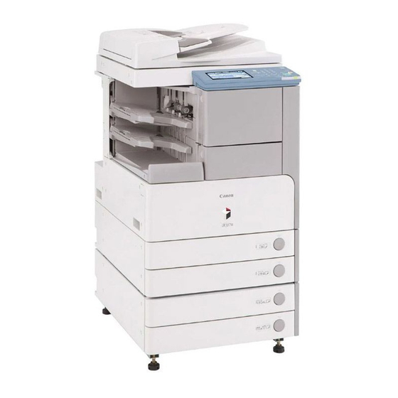
Chapter 1 1.2 Product Specifications 1.2.1 Names of Parts 1.2.1.1 Names of Parts 0007-2860 iR2270 / iR2870 / iR3570 / iR4570 [18] [17] [16] [15] [10] [14] [11] [13] [12] F-1-14 [1] ADF reading glass retainer [2] DADF [3] Reader cover (front) [4] Control panel [5] Support cover (right) [6] Support cover... -
Page 55: External View
Chapter 1 [19] [20] [21] [29] [22] [28] [23] [27] [26] [25] [24] F-1-15 [19] Reader over (right) [20] Copyboard glass [21] Reader cover (rear) [22] Face over (iR3570,4570) [23] Rear cover [24] Right cover (rear) [25] Manual feed pickup tray [26] Right cover (lower front) [27] Right door unit [28] Delivery cover... - Page 56 Chapter 1 [18] [17] [16] [15] [10] [14] [11] [13] [12] F-1-16 [1] ADF reading glass retainer [2] DADF (optional) [3] Reader cover (front) [4] Control panel [5] Support cover (right) [6] Support cover [7] Delivery tray right cover [8] Delivery tray [9] Inside right cover [10] Front cover unit...
-
Page 57: Cross-Section
Chapter 1 [20] [19] [21] [28] [22] [27] [23] [26] [25] [24] F-1-17 [19] Reader cover (right) [20] Platen glass [21] Reader cover (rear) [22] Face cover [23] Rear cover [24] Right cover (rear) [25] Manual feed pickup tray [26] Right cover (lower front) [27] Right door unit [28] Delivery cover [29] Right cover (upper) - Page 58 Chapter 1 [1] [2] [10] [11] [29] [12] [13] [28] [14] [15] [16] [17] [18] [19] [20] [21] [22] [23] [24] [26] [25] [27] F-1-18 iR3570/iR3570F/iR4570/iR4570F Model 1-26...
- Page 59 [1] [2] [10] [11] [29] [12] [13] [28] [14] [15] [16] [17] [18] [19] [20] [21] [22] [23] [24] [26] [25] [27] F-1-19 T-1-24 CIS unit [16] Manual feed pickup roller ADF reading glass [17] Pickup roller (cassette 1) Platen glass [18] Vertical path roller 1 Toner bottle...
-
Page 60: Using The Machine
Chapter 1 [11] Duplex feed roller [26] Developing unit [12] Photosensitive drum [27] Laser scanner unit [13] Duplex feed roller 2 [28] Dust-blocking sheet [14] Transfer roller [29] Sub hopper [15] Registration roller 1.2.2 Using the Machine 1.2.2.1 Turning On the Power Switch 0007-3138 iR2270 / iR2870 / iR3570 / iR4570 / iR3530 The machine possesses 2 power switches: main power switch and control power switch. - Page 61 Chapter 1 F-1-21 iR3530/2830/2230 [1]Control panel power switch [2]Main power lamp [3]Main power switch Never turn off the main power while the display shows the progress bar, indicating that the HDD is being accessed. Otherwise, the HDD may suffer a fault (E602). This caution does not apply to models not equipped with a HDD.
-
Page 62: When Turning Off The Main Power Switch
Chapter 1 1.2.2.2 When Turning Off the Main Power Switch 0007-3160 iR2270 / iR2870 / iR3570 / iR4570 / iR3530 Be sure always to turn off the control panel power switch before turning off the main power switch When Using the Print Function/When Receiving or Transmitting a Fax Before using the main power switch, check to be sure that the Execute/Memory lamp on the control panel is off. -
Page 63: Points To Note About Turning Off The Main Power Switch
Chapter 1 F-1-24 1.2.2.3 Points to Note About Turning Off the Main Power Switch 0009-1736 / iR3530 Before turning off the main power switch, you must first press the control panel power switch. When the Printer Unit Is in Operation or a Fax Is Being Received Check to be sure that the Execute/Memory lamp on the control panel is off. - Page 64 Chapter 1 F-1-25 While Downloading Is Taking Place Do not turn off the main power switch or the control panel power switch. (Otherwise, the machine may fail to operate.) 1-32...
-
Page 65: Control Panel
Chapter 1 F-1-26 1.2.2.4 Control Panel 0007-3163 iR2270 / iR2870 / iR3570 / iR4570 ON/OFF 1 2 3 Additional Function Display Contrast Clear Start/Memory Error Main Power [15] [14] [13] [12] [11] [10] F-1-27 1-33... -
Page 66: Control Panel
Chapter 1 T-1-25 [1] Reset key [9] Execute/Memory lamp [2] Keypad [10] Clear key [3] Control panel power switch [11] ID key [4] Counter Check key [12] Image contrast adjustment dial [5] Stop key [13] User Mode key [6] Start key [14] Help key [7] Main power lamp [15] Touch panel... -
Page 67: User Mode Items
Chapter 1 [7] Stop key [17] User mode key [8] Start key [18] Help key [9] Main power lamp [19] Reset key [10] Error lamp [20] Touch panel 1.2.3 User Mode Items 1.2.3.1 Common Settings 0007-3164 iR2270 / iR2870 / iR3570 / iR4570 *Factory settings. - Page 68 Mode Description register envelope cassette ENV.1/ENV.2 default: env1/COM10/env2 COM10 register paper type cassette 1/cassette 2/cassette 3/cassette 4/cassette 5 (paper deck); plain paper, recycled paper, colored paper, punched paper power consumption at sleep *low/high select special tray** (w/ - w/ No. 3 tray finisher) tray A: host middle tray tray B: No.
- Page 69 Mode Description - Finisher-S1 + option tray tray A: finisher option tray tray B: finisher output tray tray A: *copy/*Box/printer/receive/fax/other tray B: copy/Box/*printer/receive/*fax/*other fine setup for receive/fax tray A: receive/fax 1/fax 2 tray B: *receive/*fax 1/fax 2 - Finisher-S1 + No. 3 tray tray A: finisher output tray tray B: No.
- Page 70 Mode Description - w/ Fisher-Q3/Q4 tray A: finisher output tray (upper) tray B: finisher output tray (lower) tray C: host middle tray tray A: *copy/*Box/printer/receive/fax/other tray B: copy/Box/*printer/receive/fax/other tray C: copy/Box/printer/receive/*fax/*other fine tune for receive/fax tray A: fax/fax 1/fax 2 tray B: receive/fax 1/fax 2 tray C: *receive/*fax 1/*fax 2 - if w/o fax,...
-
Page 71: Common Settings
Chapter 1 Mode Description set manual feed envelope ON/*OFF (if outside Japan, fixed to on) type register manual feed paper ON (select paper size/select paper type)/*OFF standard mode switch pickup method indicate manual feed, cassettes 1 through 5 icons and paper type priority on speed/priority on print set standard mode for local select paper:*auto/cassette 1 through 5... - Page 72 Mode Description give priority to 'device' of 'system status screen': *ON/OFF function after auto clear *use previous/do not use previous enable/disable buzzer input sound: *ON/OFF Input invalid sound supply pre-alert: ON/*OFF alert: *ON/OFF job end: *ON/OFF inch input ON/*OFF (if US, *ON) enable/disable cassette auto copier/printer/box/other (manual feed: ON/*OFF + individual selection...
- Page 73 Mode Description w/ inner tray + tray 3 tray A: machine middle tray (lower) tray B: machine middle tray (upper) tray C: tray 3 tray A: *copier/box/printer/receive/fax/other tray B: copier/box/*printer/receive/fax/other tray C: copier/box/printer/receive/fax*/other* detail setup (receive/fax) tray A: receive/fax 1/fax 2 tray B: receive/fax 1/fax 2 tray C: *receive/*fax 1/*fax 2 *Fin-S1 + optional tray...
- Page 74 Mode Description Fin-S1 + optional tray + tray 3 tray A= Fin optional tray tray B= Fin output tray tray C= tray 3 tray A: *copier/*box/printer/receive/fax/other tray B: copier/box/*printer/receive/fax/other tray C: copier/box/printer/receive/*fax/*other detail setup (receive/fax) tray A: receive/fax 1/fax 2 tray B: receive/fax 1/fax 2 tray C: *receive/*fax 1/*fax 2 w/ Fin-Q3/Q4...
-
Page 75: Setting The Time
Chapter 1 Mode Description w/ output optional tray tray A: machine middle tray tray A: *copier/*box/*printer/receive/*fax/*other (There is only one output target and, therefore, the special tray is not indicated.) print priority copier: *1/2/3 printer: 1/*2/3 box: 1/2/*3 fax/fax: 1/2/*3 other: 1/2/*3 manual feed paper standard ON (paper size select/paper type select)/*OFF... -
Page 76: Setting The Timer
Chapter 1 *Factory settings. T-1-29 Mode Description set time (fine) in 1-min increments (using +/-) set auto sleep time 10, 15, 20, 30, 40, 50 min; *1 hr; 90 min, 2, 3, 4 hr auto reset time 0: disable; 1, *2, ..., 9 min (in 1-min increments) set weekly timer 00:00 to 23:59 (in 1-min increments);... -
Page 77: Adjustment And Cleaning
Chapter 1 Mode Description center bind position size: A3,11x17/B4/LGL/A4R,LTRR change** (w/ saddle finisher) position: -2.0 mm to +2.0 mm (in 0.35-mm increments)/*0 mm density correction copy/Box, transmit; 9 sets each (at time of shipment, set to '5') page print/number of set X: -8 mm to +8 mm (in 1-mm increments)/*0 mm prints adjust stamp position Y: -8 mm to +8 mm (in 1-mm increment)/*0 mm... -
Page 78: Printing Out A Report
Chapter 1 Mode Description fax (settings)*** fax transmission result report: *only if error/ON/OFF show transmission report:*ON/OFF fax communication control report print automatically every 40 communications: print at specified time: ON/*OFF set time: *00:00 to 23:59 separate transmission and reception: ON/*OFF (toggle) fax reception result report: only if error/ON/*OFF fax Box reception report: list print... -
Page 79: System Control Settings
Chapter 1 Mode Description print at specified time: ON/*OFF set time: *00:00~23:59 separate transmit and receive: (toggle) ON/*OFF fax transmission result report: *only if error/ON/OFF (specifications transmission original display: *ON/OFF settings)*** fax communication control report print automatically every 40 communications: *ON/OFF print at specified time: ON/*OFF ... - Page 80 T-1-35 Mode Description set system system administrator group ID: 7 characters max administrator info system administration ID: set (7 characters) system administrator name: 32 bytes mail address: 64 bytes contact: 32 bytes comment: 32 bytes group ID control group ID control: ON/*OFF register ID No.: register, edit, delete, limit function count control: reset, count print, all clear print without known ID: *ON/OFF...
- Page 81 Mode Description enable/disable *ON/OFF remote UI use SSL: ON/OFF limit addresses*** address book ID No.: 7 characters max. address book access No. control: ON/*OFF limit new addresses: ON/*OFF set device info device name: 32 characters installation site: 32 characters transfer setup*** reception method, conditions ON/OFF, register, register transfer without condition, e-mail priority, detail/edit, delete, list print delete bulletin...
-
Page 82: System Control Settings
Chapter 1 Mode Description limit reception by function: user mode setting: ON/*OFF group ID: ON/*OFF address book: ON/*OFF distribution/reception history: detail info 1.2.3.10 System Control Settings 0009-2488 / iR3530 *Factory default. ***Indicated when appropriate accessories are installed. T-1-36 Mode Description set system system administrator ID: 7 characters max. -
Page 83: Copy Settings
Chapter 1 Mode Description use fax memory reception***: ON/*OFF use i-fax memory reception**: ON/*OFF Memory reception start time***: every day, day of week, *no specification memory reception time***: every day, day of work, *no specification enable/disable *ON/OFF remote UI use SSL: ON/OFF limit target*** address book ID No.: 7 characters max. - Page 84 Chapter 1 Mode Description auto sort** *ON/OFF auto vertical/horizontal *ON/OFF rotation print photo mode ON/*OFF change standard mode register/reset (at time of shipment: 1 set, auto paper, auto density, auto image quality, local printer) reset copy settings Do you really want to reset? yes/no (auto sort: on;...
- Page 85 Mode Description PDF (OCR setup)*** original orientation auto detection: (*ON/OFF) number of OCR characters for file name: (1 through *24) initial transmission screen***: routine task button/one-touch button/*new address source record***: *add/do not add display location: inside image/*outside image display target abbreviation: (*ON/OFF) telephone No.
-
Page 86: Transmission/Reception Settings
Chapter 1 Mode Description set fax ECM transmission (*ON/OFF) transmission set pause length: (*1 to 15 sec/4 to 11 sec/3 to 6 sec) function auto re-dial: (*ON/OFF) number of redials: 100V: 1-15 (*2), 120V: 1-10 (*2), 230V: 1-10 (*2) intervals for redials (min): 2-99 (*2) redial at communication error: 1st page and error page/all pages/off communication mode: *G4-G3/G3 only... - Page 87 T-1-39 Mode Description set common register sender***: 01 to 99: register/edit (24 characters max), delete settings register user abbreviation***: 24 characters max. permit non-ASCII code for FTP transmission***: (ON/*OFF) delete error file***: (*ON/OFF) handle transfer error file***: print always/save/print/*OFF print photo mode***: (ON/*OFF) number of retries***: (*3 (0 to 5 times)) change transmission function standard mode*** read mode, file format, separate for page, SENT stamp...
-
Page 88: Box Settings
Chapter 1 Mode Description volume control alarm volume: 0 to 8(*4) communication volume: 0 to 8(*4) ECM transmissions (*ON/OFF) transmission pause length setting: (1 to 15 sec; 2 sec*) function setup*** auto redial: (*ON/OFF) pre-transmission dial tone check: (*ON/OFF) fax reception ECM reception: (*ON/OFF) function... -
Page 89: Box Settings
Chapter 1 1.2.3.15 Box Settings 0009-2504 / iR3530 *Factory default. ***Indicated when appropriate accessories are installed. T-1-41 Mode Description set/register user box select box: 0-99 register box name: 24 characters max. ID No.: 0-9999999 file auto delete: 0: no; 1, 2, 3, 6, 12 hr; 1, 2, *3, 7, 30 days URL transmission setting: e-mail address selection reset print photo mode... -
Page 90: Address Book Settings
Chapter 1 Mode Description adjust print super smooth: *use/do not use **toner density: 1 to 9 (*5) toner save: enable/*disable layout bind position: *long side/short side bind margin: -50to+50mm (*0.0) horizontal correction/vertical correction: -50to+50mm (*0.0) auto error skip** skip/*do not skip secure print delete time length: *1, 2, 3, 6, 12, 24 hr timeout: 5 to 300 (*15 sec)/disable RIP: yes/*no... - Page 91 Chapter 1 *If iR4570, iR3570, iR2870, or iR2270, indicated in the presence of a specific accessory (if model F, standard). T-1-43 Mode Description fax (register register name: 24 characters target) register name: 24 superscript characters telephone No.: 120 characters max. (+, pause, tone, <, >, backspace, space, ISDN sub address, F-Net, DT, R, PIN, sub settings) Sub Settings F code: 20 characters max.
- Page 92 Mode Description file (register register name: 24 characters address) register name: 24 superscript characters protocol: *FTP/Windows(SMB)/Netware(IPX) host name: 128 characters path to folder: 128 characters user name: FTP,Netware(IPX) : 24 characters Windows(SMB): 15 characters password: FTP,Netware(IPX): 24 characters Windows(SMB): 14 characters group (register register name: 24 characters target)
-
Page 93: Maintenance By The User
Chapter 1 1.2.4 Maintenance by the User 1.2.4.1 Cleaning 0007-4601 iR2270 / iR2870 / iR3570 / iR4570 / iR3530 - Copyboard Glass, Copyboard Cover (back; copyboard cover type H) Advise the user to clean the surface of the copyboard glass and the back of the copyboard cover at least once a month. Cleaning Procedure Using a cloth moistened with water or solution of mild detergent, wipe the surface of the copyboard glass [1] and the back of the copyboard cover [2];... - Page 94 Chapter 1 - Checking the Operation of the Leakage Breaker Advise the user to check the leakage breaker once or twice a month on a regular basis. Be sure also to ask the user to keep a record of checks. Inspection Procedure 1) Turn on the main power switch.
-
Page 95: Safety
Chapter 1 F-1-33 F-1-34 6) Turn on the main power switch. 1.2.5 Safety 1.2.5.1 Safety of the Laser Light 0007-3174 iR2270 / iR2870 / iR3570 / iR4570 Laser light can prove to be hazardous to the human body. The machine's laser unit is fully enclosed in a protective housing and external covers so that its light will not escape outside as long as the machine is used normally. -
Page 96: Handling The Laser Unit
Chapter 1 F-1-35 A different description may be used for a different product. 1.2.5.3 Handling the Laser Unit 0007-3176 iR2270 / iR2870 / iR3570 / iR4570 If you must service the area around the machine's laser unit, be sure to take full care to avoid exposure to laser light: do not insert a tool (e.g., screwdriver or those with a high reflectance) into the laser path;... -
Page 97: Safety Of Toner
Chapter 1 F-1-36 1.2.5.4 Safety of Toner 0007-3177 iR2270 / iR2870 / iR3570 / iR4570 The machine's toner is a non-toxic material made of plastic, iron, and small amounts of dye. Do not throw toner into fire. It may cause explosion. Toner on Clothing or Skin 1. - Page 98 Copyboard stream reading, fixed reading Body desktop Light source type LED array (CIS) Photosensitive medium OPC drum (30-mm dia.) Image reading method CCD (CIS) Reproduction method indirect electrostatic Exposure method by laser light Charging method by AC charging roller Development method 1-component toner projection Transfer method by transfer roller...
- Page 99 Number of gradations 256 gradations Reading resolution 600 x 600 dpi Copying resolution 1200 dpi (equivalent) x 600 dpi Printing resolution 2400 dpi (equivalent) x 600 dpi First print time iR 2270, iR2870, iR2230, iR2830: 4.9 sec or less; iR 3870, iR4570, iR3530: 3.9 sec or less Cassette capacity 550 sheets (80 g/m2)
-
Page 100: Function List
Chapter 1 Power consumption iR 2270, iR2870, iR2230, iR2830: standby, 36 Wh (reference only) / continuous printing: 543 Wh (reference only) iR 3570, iR4570, iR3530: standby, 37 Wh (reference only) / continuous printing: 823 Wh (reference only) Ozone max.: 0.02 ppm or less; avr: 0.01 ppm or less Dimensions 565 mm x 700 mm x 761.4 mm (WxDxH) Weight... -
Page 101: Printing Speed
Chapter 1 Single-sided Auto duplexing Paper size cassette feed manual feed cassette feed manual feed Heavy paper 23[22] STMTR 25[22] LTRR Postcard 12/8 free 25[22] 25[22] Envelope Monarch 10/6 COM10 10/6 ISO-B5 10/6 ISO-C5 10/6 10/6 YOGATA No.4 10/6 1.2.7.2 Printing Speed 0007-7696 iR3570 / iR4570 / iR3530 Max/Min (max when the machine has fully cooled) - Page 102 T-1-45 Single-sided Auto duplexing Paper cassette feed manual feed cassette feed manual feed size dlvry dlvry dlvry dlvry dlvry dlvry dlvry dlvry Plain 45[35 paper 20/16 17/14 10/8 20/16 17/14 10/8 20/16 17/14 10/8 24/16 12/8 STMTR 20/16 17/14 10/8 45[35 LTRR 20/16...
-
Page 103: Types Of Paper
Chapter 1 Single-sided Auto duplexing Paper cassette feed manual feed cassette feed manual feed size dlvry dlvry dlvry dlvry dlvry dlvry dlvry dlvry Envelop Monarc 12/8 COM10 12/8 ISO-B5 12/8 ISO-C5 12/8 12/9 yogata NO.4 12/8 1.2.7.3 Types of Paper 0007-7893 iR2270 / iR2870 / iR3570 / iR4570 T-1-46... -
Page 104: Types Of Paper
Chapter 1 Source Type Size Manual Side Paper Cassette feed tray Deck-Q1 Special Heavy A3, B4, A4R, LDR, LGL, paper paper LTRR, B5, EXE, A5R, STMTR, B5R, A4, LTR A4, LTR Postcard postcard A6R modified; double-postcard A5R modified 4-plane A4 modified postcard Label... - Page 105 Source Type Size Manual Cassette feed tray Special Heavy A3, B4, A4R, LDR, LGL, paper paper LTRR, B5, EXE, A5R, STMTR, B5R, A4, LTR A4, LTR Postcard postcard A6R modified; double-postcard A5R modified 4-plane A4 modified postcard Label A4, A4R, LTR, LTRR paper 3-hole same as plain...
- Page 107 Chapter 2 Installation...
- Page 109 Contents Contents 2.1 Making Pre-Checks ............................2-1 2.1.1 Selecting the Site of Installation ......................... 2-1 2.1.2 Before Starting the Work (230V) ........................ 2-3 2.2 Unpacking and Installation..........................2-8 2.2.1 Unpacking and Removing the Packaging Materials ................... 2-8 2.2.2 Installing the Toner Bottle......................... 2-10 2.2.3 Installing the Drum Unit..........................
-
Page 111: Making Pre-Checks
Chapter 2 2.1 Making Pre-Checks 2.1.1 Selecting the Site of Installation 0007-4754 iR2270 / iR2870 / iR3570 / iR4570 Select the site of installation against the following requirements; if possible, visit the user's before delivery of the machine: 1) There must be a power outlet properly grounded and rated as indicated (+, -10%) for exclusive use by the machine. 2) The environment of the room must be as indicated in the following diagram, and the machine must not be installed near a water faucet, water boiler, humidifier, or refrigerator: Humidity (%RH) - Page 112 Chapter 2 100 mm min. 1,035 mm F-2-2 - Without a DADF-N1, Finisher S1, and Side Paper Deck-Q1 Installed 100 mm min. 1,228 mm 1,371 mm 182 mm 1,553 mm F-2-3 - With a DADF-N1, Side Paper Deck-Q1, Saddle Finisher-Q4, Buffer Path Unit-E1, and Puncher Unit-L1/M1/N1/ P1 Installed 100 mm min.
-
Page 113: Before Starting The Work (230V)
Chapter 2 2.1.2 Before Starting the Work (230V) 0008-3400 iR2270 / iR2870 / iR3570 / iR4570 1-1 Points to Make Before Installation Be sure to go through the following before starting the work: 1) If you are installing the machine after moving it from a cold to warm location, be sure to leave the machine unpacked for at least 2 hours so that the machine is fully used to the site temperature, thus avoiding image faults caused by condensation. - Page 114 F-2-5 T-2-1 Drum unit Dial label Toner bottle (230V CA model only) [10] Size label(small) (ADF standard model only) Lower right cover [11] Shut-Down Warning 2pc* Label Adjusting screw [12] Toner Bottle Warning Label covering rubber [13] Stamp (DADF standard model only)
- Page 115 Chapter 2 Service book case [14] Power Cable Reversing Guide(iR3570 / 4570 [15] Ferrite core model only) Cassette size label *230V CA mode --- 1pc Check the documentation and CD against the following table: T-2-2 - 230V EUR model Operators manual: Users Guide Operators manual CD-ROM MEAP Admin.CD-ROM T-2-3...
- Page 116 Chapter 2 [18] [17] [16] [15] [10] [14] [11] [13] [12] F-2-6 [1] ADF reading glass retainer [2] DADF (Option) [3] Reader cover (front) [4] Control panel [5] Support cover (right) [6] Support cover [7] Delivery tray right cover [8] Delivery tray [9] Inside right cover [10] Front cover unit...
- Page 117 Chapter 2 [19] [20] [21] [29] [22] [28] [23] [27] [26] [25] [24] F-2-7 [19] Reader over (right) [20] Copyboard glass [21] Reader cover (rear) [22] Face over [23] Rear cover [24] Right cover (rear) [25] Manual feed pickup tray [26] Right cover (lower front) [27] Right door unit [28] Delivery cover...
-
Page 118: Removing The Packaging
Chapter 2 Unpacking Installation 2.2.1 Unpacking Removing the Packaging Materials 0006-6724 iR2270 / iR2870 / iR3570 / iR4570 F-2-9 1) Unpack and remove the plastic bags. - When installing a pedestal to the copier at the same 4) Close the right door of the pedestal (in the case of time, unpack it in the same way. -
Page 119: Installing The Toner Bottle
Chapter 2 1) Open the front cover [1]. F-2-11 F-2-13 9) Remove the fixing assembly release cover [1]. Reference 2) Lift the lock lever [1]. To facilitate the work, try detaching it from the front top [2] of the fixing assembly release cover [1] in the direction of the arrow. -
Page 120: Installing The Drum Unit
Chapter 2 F-2-18 F-2-16 2) Remove the waste toner box [1]. 5) Push down the lock lever [1] so that the toner bottle is secured. F-2-19 F-2-17 3) Open the right door [1]. Be sure to shift down the locking lever until it is fully horizontal;... - Page 121 Chapter 2 F-2-24 F-2-21 7) Remove the package of the drum unit, which is 5) Turn the developing assembly pressure lever [1] to provided with the product, and remove the two the left and release the pressure. drum pressure release blocks [1]. F-2-25 F-2-22 6) Remove the one screw [1] and take out the dummy...
- Page 122 Chapter 2 10) Push down the developing assembly pressure lever [1] and apply pressure. F-2-26 F-2-29 Be careful where you hold the drum unit. 11) Secure the developing assembly pressure lever with the one screw [1]. F-2-30 12) Close the right door. 13) Mount the waste toner box [1].
- Page 123 Chapter 2 After attaching the waste toner receptacle, move the waste toner full detection lever [1] up and down to make sure that the lever is moved smoothly. Faulty detection may be resulted if the lever is caught in something and is not moved smoothly. F-2-34 2) While matching the top [4] of the front cover unit against the machine, fit the lower left claw [2] of the...
-
Page 124: Securing The Copier Main Unit
Chapter 2 until the screw legs touch the bottom slightly. F-2-38 F-2-36 2) Check if the machine wobbles while it is lying on the desk or the floor, and tighten the adjusting 15) Close the front cover [1]. screws if necessary. - When it wobbles in the direction shown by the arrow A, tighten the screw at the right side in the above picture. -
Page 125: Connecting The Cable
Chapter 2 2.2.5 Connecting the Cable 0007-5059 iR2270 / iR2870 / iR3570 / iR4570 2.2.6 Stirring Toner 0007-5062 1) If you are installing a cassette pedestal, remove the iR2270 / iR2870 / iR3570 / iR4570 lattice connector cover, and fit the lattice connector [1] of the cassette pedestal to the machine. -
Page 126: Apvc Correction Of The Drum
Chapter 2 F-2-43 7) Place sheets in the cassette, and then push the cassette into the machine. F-2-41 8) Do the same operation to the other cassette. 9) If a cassette pedestal is installed, make the cassette 4) Hold the lever [1] of the side guide plate, and set the settings in reference to the installation procedure of side guide plate to the appropriate size. -
Page 127: Adjusting The Image Position
Chapter 2 4) Take out the cassettes 1 and 2. 5) Check the position of the index [1] on the adjusting plate. 2.2.9 Adjusting the Image Position 0008-2475 iR2270 / iR2870 / iR3570 / iR4570 - Adjusting the Margin (1st side; mechanical) 1) Using the cassettes 1 and 2 and the manual feeder as the source of paper, make copies, and check to be sure that the left margin L1 is 2.5 +/-1.5 mm. - Page 128 Chapter 2 F-2-50 F-2-48 image image F-2-51 F-2-49 [1]Paper feed direction [1]Paper feed direction 8) Tighten the fixing screw. 9) Tighten the fixing screw. 9) Fit the cassette 2 back in. 10) Fit the cassette 1 back in. 10) Make a copy, and check to see that the left margin 11) Make a copy, and check to be sure that the left of the image on paper picked up from the cassette 2 margin of the image on paper picked up from the...
- Page 129 Chapter 2 image F-2-54 [1]Paper feed direction 3) If not as indicated, change the small paper 2nd side horizontal registration setting. small paper: service mode F-2-52 COPIER>ADJUST>FEED-ADJ>ADJ-REF An increase of '1' will increase the left margin of the image by 0.1 mm. 4) Enter the new value (obtained as the result of the image foregoing adjustment) as the large paper 2nd side...
- Page 130 Chapter 2 not, be sure to make the following adjustments attached. - Inside the machine (Inner side of the front cover) 1) Make the following in service mode: COPIER - Locations where the louver is blocked. >ADJUST >FEED-ADJ >REGIST. - Locations where the grips are blocked.
-
Page 131: If Not Connected To A Network
Chapter 2 - Toner Bottle Warning Label 1) Open the front cover [1]. F-2-62 F-2-60 When installing the machine newly or when replacing the harness, be sure not to leave behind 2) Attach the Toner Bottle warning label [1] of the the ferrite core. - Page 132 system setup>network>Ethernet driver setup>auto detect...
-
Page 133: Checking The Connection To The Network
Chapter 2 2.3 Checking the Connection to the Network 2.3.1 Overview 0007-5605 iR2270 / iR2870 / iR3570 / iR4570 The instructions that follow apply only when the machine is connected to a network. If the user's network environment is based on TCP/IP, use the PING function to make sure that the network settings are correct. - Page 134 2) Ask the system administrator for the appropriate remote host address. 3) Enter the remote host address for PING. 4) If the result is 'OK', the connection to the network is correct. 5) If the result is 'NG', the connection to the network is not correct; start the following troubleshooting work:...
-
Page 135: Troubleshooting The Network
Chapter 2 2.4 Troubleshooting the Network 2.4.1 Overview 0007-5609 iR2270 / iR2870 / iR3570 / iR4570 The instructions that follow apply only when the machine is connected to a network. If an attempt to connect to the network fails, the following may be suspected: a.the connection between the machine and the network is faulty. -
Page 136: Checking The Images/Operations
Chapter 2 2.5 Checking the Images/Operations 2.5.1 Checking the Image Quality and Operation 0007-5619 iR2270 / iR2870 / iR3570 / iR4570 1) Place the Test Chart on the copyboard glass, and make copies using the individual cassettes as the source of paper; then, check the output images. -
Page 137: Installing The Card Reader
Chapter 2 2.6 Installing the Card Reader 2.6.1 Points to Note 0007-2705 iR2270 / iR2870 The card reader must be used in combination with the Card Reader Mounting Kit-B1. 2.6.2 Checking the Contents 0007-2707 iR2270 / iR2870 <Card Reader-C1> T-2-4 Card Reader-C1 1 pc. -
Page 138: Installation Procedure
Chapter 2 T-2-5 Card reader base 1 pc. Relay harness 1 pc. TP screw (M4x25) 1 pc. TP screw (M4x8) 1 pc. Toothed washer 2 pc. F-2-67 2.6.3 Installation Procedure 0007-2709 iR2270 / iR2870 When you have installed the Card Reader-C1, make the following selections, COPIER> FUNCTION> INSTALL> CARD, and enter the card number you will be using;... - Page 139 Chapter 2 F-2-68 1) Open the pedestal right door [1]. (if equipped with a Cassette Feeding Unit-Y2) 2) Open the lower right cover [2]. 3) Remove the 5 screws [3], and detach the right cover (rear) [4]. F-2-69 4) Remove the face plate [2] from the right cover (rear) [1] using nippers. 2-29...
- Page 140 Chapter 2 F-2-70 5) Connect the relay cable [1] to the connector of the host machine. F-2-71 6) Mount the rear right cover using 4 screws. 7) Mount the card reader [1] and the card reader base [2] using the included TP screw (M4x8) [4]. Be sure to use the washer [3] when doing so.
- Page 141 Chapter 2 F-2-73 9) Connect the cable [1] of the machine and the relay cable [2] of the card reader. F-2-74 10) While making sure that the harness will not be trapped, mount the card reader [1] using a TP screw (4x25) [3] fitted with a washer [2].
-
Page 142: Installation In A Netspot Accountant (Nsa) Environment
Chapter 2 enter the appropriate card number (1 to 2001). -Use the number that is the lowest of all the numbers that the user will be using. -As many as 1000 cards may be used starting with the number entered. 13) Turn off the control panel power switch. -
Page 143: Installing The Ne Controller
Chapter 2 2.7 Installing the NE Controller 2.7.1 Installing the NE Controller-A1 0007-5625 iR2270 / iR2870 / iR3570 / iR4570 When installing the NE Controller-A1 to its host machine, take note of the following: 1. be sure to perform the work in compliance with the laws and regulations of the country in question. 2. - Page 144 Chapter 2 F-2-78 4) Connect the cable [1] to the connector [2] of the host machine (intended for an NE controller). F-2-79 5) Secure the controller [1] to the host machine's rear cover using 4 screws [2]. F-2-80 6) Take up the slack from the cable connecting the host machine and the controller; bundle the excess length on the controller side, and fix it in place using a harness guide [1].
- Page 145 Chapter 2 F-2-81 7) Shift bit 4 of the DIP switch [1] (SW2-4) found on the PCB of the controller to ON (so that the communication mode between the host machine and the controller will be IPC). LED1 LED2 LED3 BAT1 LED5 LED6...
- Page 146 Chapter 2 If IC6 [1] is not found, you need not mount any. If you are mounting a ROM (IC6) [1] or replacing it for upgrading the connector, be sure to shift bit 7 of the DIP switch [2] (SW2-7) to ON. 9) Set the bits of the DIP switch [1] (SW3) on the PCB as indicated in the table.
- Page 147 Chapter 2 10) Connect the power supply unit to the power outlet, and check to see that LED1 [1] (green) on the PCB goes on. LED1 LED2 LED3 BAT1 LED5 LED6 LED4 F-2-85 11) Execute RAM initialization. Set the bits of the DIP switch [1] (SW-2) on the PC as indicated in the table; then, press the push switch [2]. A press on the push switch [2] (SW4) will causes LED5 [3] (red) to go on.
- Page 148 Chapter 2 LED1 LED2 LED3 BAT1 LED5 LED6 LED4 F-2-86 12) After making sure that LED5 [3] (red) has gone on, set the bits of the DIP switch [1] (SW2) on the PCB as indicated in the table; then, press the push switch [2] (SW4). A press on the push switch [2] (SW4) will cause LED5 [3] (red) to go off, indicating that the RAM has been initialized.
- Page 149 Chapter 2 LED1 LED2 LED3 BAT1 LED5 LED6 LED4 F-2-87 13) Shift bit 6 of the DIP switch [1] (SW2-6) on the PCB to OFF. LED1 LED2 LED3 BAT1 LED5 LED6 LED4 F-2-88 14) Connect the telephone line to the controller. If you are using the controller on its own, connect the modular jack cable to the connector [1] (LINE) of the controller.
- Page 150 Chapter 2 LED1 LED2 LED3 BAT1 LED5 LED6 LED4 F-2-89 15) Call the service station, and ask for initial settings for the controller. (When a call comes in, LED 4 [1] (red) will start to flash.) LED1 LED2 LED3 BAT1 LED5 LED6...
- Page 151 Chapter 2 LED1 LED2 LED3 BAT1 LED5 LED6 LED4 F-2-91 18) Check to make sure that the communication between the host machine and the controller is correct. Connect the power plug of the host machine, and turn on its power switch to see that LED2 [1] (orange) flashes. LED1 LED2 LED3 BAT1 LED5...
- Page 152 F-2-94...
- Page 153 Chapter 3 Basic Operation...
- Page 155 Contents Contents 3.1 Construction ............................... 3-1 3.1.1 Functional Construction ..........................3-1 3.1.2 Major PCB Wiring diagram ........................3-2 3.2 Basic Sequence..............................3-5 3.2.1 Basic Sequence of Operation at Power-On ....................3-5...
-
Page 157: Construction
Chapter 3 3.1 Construction 3.1.1 Functional Construction 0008-0985 iR2270 / iR2870 / iR3570 / iR4570 The machine may broadly be divided into the following functional blocks: general control system, original exposure system, reader control system, printer control system, laser exposure system, image formation system, pickup/feed system, fixing/delivery system. -
Page 158: Major Pcb Wiring Diagram
Chapter 3 Printer Control System transfer DC controller PCB fixing Laser Exposure System delivery/reversal/duplex assembly Image Formation System pickup control Fixing/Delivery System cassette 1 Pickup/Feed System cassette 2 3.1.2 Major PCB Wiring diagram 0008-0984 iR2270 / iR2870 / iR3570 / iR4570 The following is a wiring diagram showing the relationship among major PCBs:... - Page 159 J501 J502 J6801 J6802 J1110 J1111 [13] J1113 [12] J603 J601 J511 J1018A J318 J316 J1016 J1018B J301 J1029 J307A J311 J310 J321 J1021 J1020 J315 J1027 J404 J211 J219 J216 J217 J218 J640 J647 [11] J203 J1302 J1303 J212 J210 J1301 [10]...
- Page 160 Chapter 3 AC drive PCB [16] Lower cassette size PCB Memo:The arrows in the diagram indicate the wring between PCBs, and do not indicate the direction of individual signals.
-
Page 161: Basic Sequence
Chapter 3 3.2 Basic Sequence 3.2.1 Basic Sequence of Operation at Power-On 0008-1235 iR2270 / iR2870 / iR3570 / iR4570 1. Reader Unit Shading correction CIS output Main power offset correction switch ON SREADY STBY Reader motor (M501) CIS HP sensor (PS503) Shading Shading... - Page 163 Chapter 4 Main Controller...
- Page 165 Contents Contents 4.1 Construction ............................... 4-1 4.1.1 Construction and Mechanisms ........................4-1 4.1.2 Construction and Functions......................... 4-2 4.2 Construction of the Electrical Circuitry ......................4-4 4.2.1 Main Controller PCB........................... 4-4 4.2.2 Main Controller PCB........................... 4-5 4.2.3 HDD ................................4-7 4.2.4 HDD (optional)............................4-9 4.3 Start-Up Sequence............................
- Page 166 Contents 4.7.3 Boot ROM ..............................4-36 4.7.3.1 Removing the Face Cover........................4-36 4.7.3.2 Removing the Boot ROM ........................4-37 4.7.4 HDD................................4-38 4.7.4.1 Removing the Face Cover........................4-38 4.7.4.2 Removing the Face Cover (optional)....................4-38 4.7.4.3 Removing the Counter PCB ....................... 4-39 4.7.4.4 Removing the Counter PCB (optional)....................
-
Page 167: Construction
Chapter 4 4.1 Construction 4.1.1 Construction and Mechanisms 0006-6582 iR2270 / iR2870 / iR3570 / iR4570 The machine's main controller block consists of the following and has the following functions: T-4-1 Item Description Main controller PCB Controls system operation, memory, printer unit output, image processing, printer unit image input processing, rendering, color LCD... -
Page 168: Construction And Functions
Chapter 4 Reader unit DC controller PCB Main controller PCB Image memory (SDRAM) Riser board USB port Ethernet 10/100BASE-T SRAM Boot ROM Hard disk drive F-4-1 4.1.2 Construction and Functions 0008-8054 / iR3530 The machine's main controller block consists of the following components arranged as shown: T-4-2 Item Description... - Page 169 Item Description HDD (optional) stores system software stores image data for Box/Fax functions 20 GB USB port USB2.0 interface Ethernet port Ethernet interface (10/100 Base-T) Reader Unit DC controller PCB Main controller PCB Image memory (SDRAM) USB port Ethernet 10/100BASE-T SRAM Boot ROM Hard disk drive...
-
Page 170: Construction Of The Electrical Circuitry
Chapter 4 4.2 Construction of the Electrical Circuitry 4.2.1 Main Controller PCB 0006-6592 iR2270 / iR2870 / iR3570 / iR4570 The following is a diagram showing the major control mechanisms of the main controller according to connectors: J1014 J1004 J1016 J1028 J1003... -
Page 171: Main Controller Pcb
Chapter 4 Connector Description J1013 Riser board connection slot J1014 Scanner DDI J1017 USB port J1018 Control panel connector J1020 Power supply connector J1026 Hard disk connector J1029 Printer DDI J1030 Fax connector (1-port) J1061 Ethernet port (10/100BaseT) 4.2.2 Main Controller PCB 0009-0473 / iR3530 The machine's main controller PCB has the following functions (shown according to connectors):... - Page 172 J1014 J1004 J1016 J1028 J1003 J1029 IC1005 IC1010 J1018 J1017 J1024 IC1084 J1006 IC1008 J1013 IC1009 IC1004 IC1100 J1061 J1062 IC1003 BATTERY IC1001 J1010 IC1006 J1026 J1023 IC1002 J1022 J1060 J1030 J1005 J1020 J1059 J1027 J1021 F-4-4 T-4-4 Connector Description J1003 SDRAM connection slot J1004...
- Page 173 Chapter 4 Connector Description J1029 printer DDI J1030 fax connector (1-line) J1061 Ethernet pot (10/100Base-T) 4.2.3 HDD 0008-4957 iR2270 / iR2870 / iR3570 / iR4570 The HDD is divided into 11 partitions (blocks), each assigned with specific functions. T-4-5 Partition Description FSTDEV Collects compressed image data.
- Page 174 Chapter 4 FSTDEV TMP_GEN TMP_PSS TMP_FAX APL_SEND APL_MEAP APL_GEN IMG_MNG PDLDEV BOOTDEV FSTCDEV F-4-5 The following shows the construction of the machine's system software: T-4-6 System software Description Location Remarks System System module (controls HDD (BOOTDEV) mechanism as a whole) Language Language module HDD (BOOTDEV)
-
Page 175: Hdd (Optional)
Chapter 4 RCON Reader unit DCON Main controller PCB DC controller PCB BOOT SYSTEM Language BOOTDEV BOOTDEV MEAP G3FAX F-4-6 4.2.4 HDD (optional) 0008-8061 / iR3530 The HDD is divided into 11 partitions (blocks), each assigned with specific functions. T-4-7 Partition Description FSTDEV... - Page 176 Chapter 4 Partition Description APL_MEAP Stores MEAP applications. APL_GEN Mode memory data, standard mode data History (e.g., print job history) iFax image data Fax image data Other IMG_MNG Stores file management table, profile. PDL_DEV Stores PDL font, etc. BOOTDEV Stores execution module, message data file, RUI content, etc.
- Page 177 System software Description Location Remarks Boot Starts up the machine BootROM DIMM (FAX board) G3FAX Controls G3 Fax HDD (BOOTDEV) 1-line Dcon Controls the DC DC controller PCB Mask controller (soldered) Rcon Controls the printer unit Printer unit controller Flash controller (soldered) Meapcont...
-
Page 178: Start-Up Sequence
Chapter 4 4.3 Start-Up Sequence 4.3.1 Overview 0006-6702 iR2270 / iR2870 / iR3570 / iR4570 The system software used to control the machine is stored on the HDD. When the machine is started, the CPU on the main controller PCB reads the system software from the HDD according to the instructions of the boot ROM boot program, and writes it to the image memory (SDRAM) of the controller PCB. - Page 179 The machine will indicate an error code if it finds a fault while running the program. - Boot Program (interval 2) When the self-diagnosis program ends normally, the CPU on the main controller PCB executes the boot program. The program is used to read the system software from the HDD to write it into the image memory (SDRAM). <Image Memory (SDRAM) Area>...
- Page 180 - While the Self-Diagnosis Program Is Being Executed Image memory (SDRAM) System Image data area area Boot Self diagnosis program program BootROM Main controller PCB : access to the program during execution : access for checking F-4-11 - While the Boot Program Is Being Run Image memory (SDRAM) System area Image data...
-
Page 181: Shut-Down Sequence
Chapter 4 4.4 Shut-Down Sequence 4.4.1 Overview 0006-8356 iR2270 / iR2870 / iR3570 / iR4570 If the main power switch is turned off while the machine is accessing its HDD, damage can well occur on the HDD. To avoid such damage, the machine is provided with a shut-down sequence. 4.4.2 Overview (w/ HDD) 0008-8064 / iR3530... - Page 182 Moves to the shut-down sequence. Press on the control panel power switch (3 sec or more) Indicates the job being executed, and informs the user that it will start the shut-down sequence. protection check mode Cancels any job on wait in print mode. Cancels any job on wait in print mode.
-
Page 183: Image Processing
Chapter 4 4.5 Image Processing 4.5.1 Overview of the Image Flow 0006-6704 iR2270 / iR2870 / iR3570 / iR4570 The following shows the flow of images in relation to the machine's functions: Other iR machine Original Copy Scan -SEND -FAX -PullScan -E-Mail -PDL Print... -
Page 184: Construction Of The Image Processing Module
Chapter 4 Reader unit Reader unit controller PCB Reader unit input image processing block Processes the image data read by the reader unit. Printer unit output image processing block Processes image data for output to the printer unit. Main controller PCB DC controller PCB SDRAM - image memory... -
Page 185: Reader Unit Input Image Processing
Chapter 4 Reader unit Reader unit controller PCB Reader unit input image processing block Processes the image data read by the reader unit. Printer unit output image processing block Processes image data for output to the printer unit. Main controller PCB DC controller PCB SDRAM (optional) -
Page 186: Compressio/ Extesion/ Editing Block
Chapter 4 Reader unit Main controller PCB Enlargement/reduction Edge emphasis -intensify-to-density conversion -density adjustment (F adjustment) -gamma correction Text mode Film photo mode Text/photo/film photo mode Binary processing (error diffusion) Binary processing (screen processing) To compression/expansion/editing block F-4-18 4.5.5 Compressio/ Extesion/ Editing Block 0006-6714 iR2270 / iR2870 / iR3570 / iR4570 Here, image data is processed for compression, extension, and editing. -
Page 187: Compression/Expansion/Edit Block
Chapter 4 Main controller PCB Printer unit image PDPDL image processing block processing block SDRAM Enlargement/ Compression reduction Expansion Rotation Integration to printer unit output image processing block F-4-19 4.5.6 Compression/Expansion/Edit Block 0009-1741 / iR3530 In this block, machine executes compression, expansion, and editing tasks. Main controller PCB Reader image PDL image... - Page 188 Chapter 4 The main controller processes the image data coming from the printer unit for output to the printer unit. Main controller PCB Compression/expansion/editing block Binary density conversion Enlargement/reduction Smoothing For PDL data, Thickening when fine line processing is ON To DC controller PCB F-4-21 4-22...
-
Page 189: Flow Of Image Data
Chapter 4 4.6 Flow of Image Data 4.6.1 Flow of Image Data According to Copy Functions 0006-6746 iR2270 / iR2870 / iR3570 / iR4570 The following is the flow of image data when the Copy Function is in use: Printer unit Main control PCB Image processing block for printer unit SDRAM... -
Page 190: Flow Of Image Data For The Box Function
Chapter 4 Reader unit Main control PCB Reader image processing block SDRAM Data rotation Data compression (option) Data expansion Printer image processing block (raw data) DC controller PCB F-4-23 4.6.3 Flow of Image Data for the Box Function 0006-6747 iR2270 / iR2870 / iR3570 / iR4570 The following is the flow of image data when the Box function is in use: Printer unit... -
Page 191: Flow Of Image Data For The Box Function
Chapter 4 4.6.4 Flow of Image Data for the Box Function 0009-1744 / iR3530 The following shows the flow of image data when the BOX function is in use: Reader unit Main controller PCB Reader image processing block SDRAM Data rotation (optional) Data compression F-4-25... -
Page 192: Flow Of Image Data For The Send Function
Chapter 4 Printer unit Main controller PCB Image processing block for printer unit SDRAM Data expansion Data rotation Resolution conversion Ethernet port To network F-4-26 4.6.6 Flow of Image Data for the SEND Function 0009-1745 / iR3530 The following is the flow of image data when the SEND function is in use: 4-26... -
Page 193: Flow Of Image Data For The Fax Transmission
Chapter 4 Reader unit Main controller PCB Reader image processing block SDRAM Data expansion Data rotation (optional) Resolution conversion Ethernet port To network F-4-27 4.6.7 Flow of Image Data for the Fax Transmission 0006-6750 iR2270 / iR2870 / iR3570 / iR4570 The following is the flow of image data when the fax transmission function is in use: 4-27... -
Page 194: Flow Of Image Data For The Fax Transmission Function
Chapter 4 Reader unit Main controller PCB Image processing block for reader unit SDRAM Compression Compression Expansion Image processing block for fax Resolution conversion Super G3 Fax Board F-4-28 4.6.8 Flow of Image Data for the Fax Transmission Function 0009-1746 / iR3530 The following shows the flow of image data when the fax transmission function is in use:... -
Page 195: Flow Of Image Data For The Fax Reception Function
Chapter 4 Reader unit Main control PCB Reader image processing block SDRAM Compression Rotation (optional) Expansion Fax image processing block Super G3 fax board F-4-29 4.6.9 Flow of Image Data for the Fax Reception Function 0006-6751 iR2270 / iR2870 / iR3570 / iR4570 The following is the flow of image data when the fax reception function is in use: 4-29... -
Page 196: Flow Of Image Data For The Fax Reception Function
Chapter 4 Super G3 Fax Board Main controller PCB Image processing block for fax SDRAM Data rotation Data compression Data expansion Image processing block for printer unit DC controller PCB F-4-30 4.6.10 Flow of Image Data for the Fax Reception Function 0009-1747 / iR3530 The following shows the flow of image data when the fax reception function is in use:... -
Page 197: Flow Of Image Data For The Pdl Function
Chapter 4 Sure G3 fax board Fax image processing block SDRAM (optional) DC controller PCB F-4-31 4.6.11 Flow of Image Data for the PDL Function 0006-6752 iR2270 / iR2870 / iR3570 / iR4570 The following is the flow of image data when the PDL function is in use: 4-31... -
Page 198: Flow Of Image Data For The Pdl Function
Chapter 4 Ethernet Main controller PCB Rendering processing block SDRAM Compression/expansion /editing block Processing block for printer unit DC controller PCB F-4-32 4.6.12 Flow of Image Data for the PDL Function 0009-1748 / iR3530 The following shows the flow of image data when the PDL function is in use: Ethernet Main controller PCB Rendering processing block... -
Page 199: Main Controller Pcb
Chapter 4 Parts Replacement 1) Disconnect the connector [1]. Procedure 4.7.1 Main Controller PCB 4.7.1.1 Removing the Rear Cover 0007-6401 iR2270 / iR2870 / iR3570 / iR4570 / iR3530 F-4-35 1) Remove the 13 screws [1] and then the other screw [2];... -
Page 200: Sdram
Chapter 4 4.7.2 SDRAM 4.7.2.1 Removing the Face Cover 0007-6411 iR2270 / iR2870 / iR3570 / iR4570 / iR3530 1) Remove the 4 screws [1]. 2) Loosen the 2 screws [2]. F-4-37 Points to Note When Replacing the Main Controller Remove the following components of the detached main controller PCB. -
Page 201: Boot Rom
Chapter 4 F-4-41 4.7.3 Boot ROM F-4-43 4.7.3.1 Removing the Face Cover 4.7.3.2 Removing the Boot 0007-6413 0007-6414 iR2270 / iR2870 / iR3570 / iR4570 / iR3530 iR2270 / iR2870 / iR3570 / iR4570 / iR3530 1) Remove the 4 screws [1]. 2) Loosen the 2 screws [2]. -
Page 202: Removing The Face Cover (Optional)
Chapter 4 F-4-45 F-4-47 3) Pull off the face cover [1] in upward direction. 3) Pull off the face cover [1] in upward direction. F-4-46 F-4-48 4.7.4.2 Removing the Face 4.7.4.3 Removing the Counter Cover (optional) 0009-2005 0008-2478 / iR3530 iR2270 / iR2870 / iR3570 / iR4570 1) Remove the 4 screws [1]. -
Page 203: Removing The Counter Pcb (Optional)
Chapter 4 F-4-51 F-4-49 4.7.4.6 Removing the HDD (optional) 4.7.4.4 Removing the Counter 0009-2007 PCB (optional) / iR3530 0009-2006 / iR3530 1) Remove the 2 screws [1], and detach the HDD [2] in the direction of the arrow. 1) Remove the screw [1], and detach the counter PCB [2]. - Page 205 Chapter 5 Original Exposure System...
-
Page 207: Parts Replacement Procedure
Contents Contents 5.1 Construction ............................... 5-1 5.1.1 Specifications, Control Mechanisms, and Functions .................. 5-1 5.1.2 Major Components ............................5-2 5.1.3 Construction of the Control System ......................5-4 5.1.4 Reader Controller PCB..........................5-5 5.2 Basic Sequence..............................5-7 5.2.1 Basic Sequence of Operation at Power-On ....................5-7 5.2.2 Basic Sequence of Operation in Response to a Press on the Start ............. - Page 208 Contents 5.4.3 Scanner Motor ............................5-37 5.4.3.1 Removing the Reader Rear Cover ...................... 5-37 5.4.3.2 Removing the Scanner Motor ......................5-37 5.4.4 Contact sensor............................5-38 5.4.4.1 Removing the Reader Front Cover ..................... 5-38 5.4.4.2 Removing the Reader Rear Cover ...................... 5-40 5.4.4.3 Removing the Copyboard Glass ......................
-
Page 209: Construction
Chapter 5 5.1 Construction 5.1.1 Specifications, Control Mechanisms, and Functions 0006-5712 iR2270 / iR2870 / iR3570 / iR4570 / iR3530 The major specifications, control mechanisms, and functions of the machine's original exposure system are as follows: T-5-1 Item Description Original exposure by LED array, indirect (LED + photoconducting body) Original scan in book mode: scan by moving contact image sensor (CIS) -
Page 210: Major Components
Chapter 5 Item Description number of lines: 1 Number of pixels: Total 7488 (Number of effective pixels: 7180) maximum original read width: 304 mm CIS drive control by reader motor (M501) Original size [1]Book Mode identification in main scanning by reflection type sensor (AB/Inch) direction: in sub scanning... - Page 211 [12] [11] [10] F-5-1 T-5-2 Item Notation Description Original cover open/ PS501 photo interrupter: detects the state (open/ closed sensor (rear) closed) of the copyboard cover; starts original size indication when the original cover is at 25 deg. Reader controller controls the drive of the reader unit, and controls image processing Original sensor 3...
-
Page 212: Construction Of The Control System
Chapter 5 Item Notation Description [10] Contact image sensor uses LEDs for indirect exposure (LED + (CIS) photoconducting body) [11] CIS HP sensor PS503 photo interrupter: detects CIS home position [12] Cupboard cover PS502 ends original size identification with the open/closed sensor copyboard cover at 5 deg. -
Page 213: Reader Controller Pcb
Chapter 5 [7] Reader motor (M501) [8] Contact image sensor [9] Image signal [10] CIS HP sensor (PS503) [11] Copyboard cover open/closed sensor (front: PS502) [12] Copyboard cover open/closed sensor (rear: PS503) 5.1.4 Reader Controller PCB 0006-5718 iR2270 / iR2870 / iR3570 / iR4570 / iR3530 The machine's reader controller PCB has the following functional construction: DC24V DC13V... - Page 214 Jack No. Description J504 communication with the ADF. J505 connects to the main motor. J506 copyboard cover open/closed sensor; connects to the CIS HP sensor J507 connects to original sensor 1, original sensor 2. J508 connects to original sensor 3, original sensor 4. J510 connects to the contact image sensor (CIS).
-
Page 215: Basic Sequence
Chapter 5 5.2 Basic Sequence 5.2.1 Basic Sequence of Operation at Power-On 0006-5719 iR2270 / iR2870 / iR3570 / iR4570 / iR3530 Shading correction CIS output Main power offset correction switch ON SREADY STBY Reader motor (M501) CIS HP sensor (PS503) Shading Shading... -
Page 216: Basic Sequence Of Operation In Response To A Press On The Start Key (Adf Mode; 1 Original )
Chapter 5 Only if 1 sec or more has passed since previous rotation Shading correction start key STBY SCFW SCRW STBY Reader motor (M501) CIS HP sensor (PS503) Original trailing edge Copy board read Shading position Shading position start position Shading position forward reverse... - Page 217 Only if 1 min or more passed since previous rotation Shading correction Start key SREADY STBY SCRW SCFW STBY Reader motor (M501) CIS HP sensor (PS503) Shading Stream reading Shading Shading Shading Original position position start position position position trailing edge forward reverse F-5-8...
-
Page 218: Various Control
Chapter 5 5.3 Various Control 5.3.1 Controlling the Scanner Drive System 5.3.1.1 Outline 0006-5722 iR2270 / iR2870 / iR3570 / iR4570 / iR3530 The machine's scanner system consists of the following components: Reader motor Reader controller PCB Carriage drive belt Copyboard cover open/closed sensor (PS501) - Page 219 Chapter 5 The reader motor driver turns on/off the reader motor and controls the direction/speed of its rotation according to the signals from the CPU. Reader controller PCB 3.3V +24V OPT_MCK J505 MD_POW Motor M501 M_ENABLE driver RETURN M_VREF F-5-11 <Memo>...
-
Page 220: Contact Image Sensor (Cis)
Chapter 5 5.3.2 Contact Image Sensor (CIS) 5.3.2.1 Outline 0006-5927 iR2270 / iR2870 / iR3570 / iR4570 / iR3530 The machine uses a contact image sensor (CIS) to expose and read an image, and the image is read on a line-by-line basis. -
Page 221: Analog Control Inside The Contact Image Sensor
Chapter 5 Image read line Light guide LED (R/G/B) Copyboard glass Rod lens array scanning direction CCD array LED (R/G/B) Light guide Rod lens array Light guide F-5-13 5.3.2.2 Analog Control Inside the Contact Image Sensor 0006-5928 iR2270 / iR2870 / iR3570 / iR4570 / iR3530 The contact image sensor (CIS) is used to control analog image processing in the following flow of work: The light reflected by the original is collected by the rod lens array;... -
Page 222: Enlargement/Reduction
Chapter 5 Ideal output characteristics Output CCD channel x 8 Actual output characteristics Input F-5-14 Be sure to correct the output among the channels using the following service mode items: -if you have replaced the contact image sensor (CIS) and, as a result, a discrepancy occurs in the output of image density among channels;... - Page 223 Chapter 5 To vary the magnification in sub scanning direction, the machine operates as follows depending on the selected method of reading the original and the selected rate of magnification: 1. In Book Mode To suit the selected rate of magnification, the speed at which the original is read is varied and the data is processed by the reader controller PCB/main controller PCB.
-
Page 224: Detecting The Size Of Originals
Chapter 5 5.3.4 Detecting the Size of Originals 5.3.4.1 Outline 0006-5731 iR2270 / iR2870 / iR3570 / iR4570 / iR3530 The machine identifies the size of the original with reference to the presence/absence of output levels of the reflecting type sensors;... -
Page 225: Outline Of Size Identification
Chapter 5 AB-Configuration Sub scanning direction Butting position Index plate Original sensor 3 Original sensor 4 Original sensor 1 Original sensor 2 Inch-Configuration Sub scanning direction Index plate Butting position Original sensor 5 Original sensor 3 STMT-R LTR-R Original sensor 1 11"... - Page 226 Chapter 5 2. The copyboard cover is opened (with cover angle at 25 deg or more). original sensor: off Original sensor 3 Original sensor 4 Original sensor 1 Original sensor 2 F-5-17 3. The copyboard cover is closed (with cover angle at 25 deg). ...
-
Page 227: Dirt Sensor Control
Chapter 5 the sensor level). Original sensor 3 Original sensor 4 Original (A4R) Original sensor 1 Original sensor 2 Change absent Change present F-5-20 The machine uses the following in reference to changes occurring in the sensor output as found in original size identification processing 1 and original size identification processing 2: AB-Configuration Inch-Configuration... - Page 228 Chapter 5 Start key Main power switch STBY WMUPR SCAN SCAN Dust detection control Dust detection control Dust detection control F-5-22 <Particulars of Control> -At the End of a Job (dust detection) The contact image sensor (CIS) checks the light reflected by the surface of the platen roller of the ADF at the read point for the presence/absence of dust.
- Page 229 Chapter 5 -Between Sheets The machine does not move the contact image sensor (CIS) for dust detection between sheets. It reads the original using the position determined at the end or start of a job; if the presence of dust is detected, however, the machine will execute image correction.
-
Page 230: Image Processing
Chapter 5 5.3.6 Image Processing 5.3.6.1 Outline 0006-5930 iR2270 / iR2870 / iR3570 / iR4570 / iR3530 The following shows the major specifications and functions of the machine's image processing system: T-5-8 number of lines: 1 Number of pixels: Total 7488 (Number of effective pixels: 7180) size of pixel: 32 x 46.9 ym Shading correction... -
Page 231: Ccd Drive
Chapter 5 Contact image sensor CIS) CCD(1 line) Reader controller PCB Analog image signal control signal drive control Gain EEP-ROM correction Target value data Analog image SRAM processing -gain correction conversion J502 Digital Digital -offset correction image signal image signal Shading correction CCD/AP circuit... -
Page 232: A/D Conversion Of The Ccd Output
Chapter 5 level (offset correction). 5.3.6.4 A/D Conversion of the CCD Output 0006-5933 iR2270 / iR2870 / iR3570 / iR4570 / iR3530 The analog video signal is further converted into a digital signal that is suited to the voltage level of individual pixels by the A/D converter. - Page 233 CCD output Characteristics after correction Target value Characteristics before correction Measurement White Original density Standard white plate F-5-28...
-
Page 234: Copyboard Glass
Chapter 5 Parts Replacement Procedure 5.4.1 Copyboard glass 5.4.1.1 Removing Copyboard Glass 0006-9714 iR2270 / iR2870 / iR3570 / iR4570 / iR3530 1) Open the copyboard cover (or ADF). 2) Remove the 2 screws [1], and detach the glass retainer [2];... -
Page 235: Reader Controller Pcb
Chapter 5 F-5-32 F-5-31 2) Open the copyboard cover (or the ADF). 3) Remove the 4 screws [1], and detach the reader rear cover [2]. When removing the ADF reading glass, take care not to touch the glass surface.The presence of dirt can cause white/black lines in the images. -
Page 236: Removing The Flexible Cable Cover
Chapter 5 F-5-36 F-5-34 When removing the copyboard glass, take care not to 5.4.2.4 Removing the flexible touch the following: cable cover 0007-3566 - glass surface - standard white plate iR2270 / iR2870 / iR3570 / iR4570 / iR3530 The presence of dirt can cause white/black lines in the 1) Remove the 4 screws [1], and detach the flexible images. -
Page 237: Removing The Reader Controller Pcb
Chapter 5 F-5-38 2) Disconnect the connector [1], and detach the flexible cable [2]. F-5-37 F-5-39 5.4.2.6 Removing the Reader 3) Remove the 8 screws [2], and detach the cover [3]. Controller PCB 0007-0745 iR2270 / iR2870 / iR3570 / iR4570 / iR3530 1) Remove the cover [1]. - Page 238 Chapter 5 wire saddles [2]; then, remove the 2 screws [3]. F-5-44 8) Disconnect the 2 connectors [1], and free the cable from the wire saddle [2]. F-5-41 5) Go to the back of the machine, and free the cable from the 5 wire saddles [1];...
-
Page 239: After Replacing The Reader Controller Pcb Or After Initializing The Ram
Chapter 5 (fixed reading) COPIER>ADJUST>ADJ-XY>ADJ-Y a-3. shading position adjustment (fixed reading) COPIER>ADJUST>ADJ-XY>ADJ-S a-4. main/sub scanning direction MTF value COPIER>ADJUST>CCD>MTF-MG If the value of the following was not 0 before the replacement reader controller PCB: COPIER>OPTION>BODY>CCD-LUT. F-5-47 Set a value other than '0' once again, and make the following adjustments using the D-10 Chart. -
Page 240: Scanner Motor
Chapter 5 cover [2]. COPIER>FUNCTION>INSTALL>STRD- c. white level adjustment COPIER>FUNCTION>CCD>DF-WLVL1 COPIER>FUNCTION>CCD>DF-WLVL2 When you have finished the foregoing adjustments, put the P-PRINT printout [1] you have previously generated in the service book cassette to replace the old P-PRINT printout. F-5-50 5.4.3.2 Removing the Scanner Motor 0006-9746... -
Page 241: Contact Sensor
Chapter 5 F-5-52 F-5-54 5.4.4 Contact sensor 4) Remove the 2 screws [1], and detach the reader 5.4.4.1 Removing the Reader front cover [2]. Front Cover 0006-9758 iR2270 / iR2870 / iR3570 / iR4570 / iR3530 1) Open the copyboard cover (or ADF). 2) Remove the 2 screws [1], and detach the copyboard glass retainer (right) [2]. -
Page 242: Removing The Copyboard Glass
Chapter 5 F-5-56 F-5-58 2) Open the copyboard cover (or the ADF). 3) Remove the 4 screws [1], and detach the reader rear When removing the copyboard glass, take care not to cover [2]. touch the following: - glass surface - standard white plate The presence of dirt can cause white/black lines in the images. -
Page 243: Removing The Contact Image Sensor (Cis)
Chapter 5 F-5-60 2) Remove the 2 screws [1], and detach the plate [2]. F-5-61 3) Remove the flexible cable [1], and detach the contact image sensor (CIS) [2]. F-5-59 5.4.4.4 Removing the Contact Image Sensor (CIS) 0006-9762 iR2270 / iR2870 / iR3570 / iR4570 / iR3530 1) Pull the drive belt (front) [1] in the direction of the arrow so that the contact image sensor (CIS) [2] will move where it is shown in the figure. -
Page 244: After Replacement Of The Cis
Chapter 5 assembly. Light guide Rod lens array F-5-63 MTF-MG When mounting it, be sure to connect the flexible F-5-65 cable [1] before fitting the contact image sensor (CIS) [2] to the machine. Be sure also to update the value indicated on the service label found behind the left cover of the reader unit so that it is identical to the value indicated on the CIS label. -
Page 245: Contact Sensor Hp Sensor
Chapter 5 F-5-66 F-5-68 2) Open the copyboard cover (or the ADF). 3) Remove the 4 screws [1], and detach the reader rear 2) Detach the 2 sensors [1] from the sensor base. cover [2]. え F-5-69 5.4.6 Contact Sensor HP Sensor F-5-67 5.4.6.1 Removing... -
Page 246: Removing The Copyboard Glass
Chapter 5 F-5-70 When removing the copyboard glass, take care not to touch the following: - glass surface - standard white plate The presence of dirt can cause white/black lines in the images. If dirt is found, clean it with lint-free paper moistened with alcohol. -
Page 247: Removing The Contract Sensor Home Position Sensor
Chapter 5 under the claw [2] found at the rear. F-5-72 When removing the ADF reading glass, take care not F-5-74 to touch the glass surface.The presence of dirt can cause white/black lines in the images. If dirt is found, be sure to clean it using lint-free paper moistened with alcohol. -
Page 248: Removing The Copyboard Glass
Chapter 5 F-5-76 F-5-78 2) Open the copyboard cover (or the ADF). 3) Remove the 4 screws [1], and detach the reader rear When removing the copyboard glass, take care not to cover [2]. touch the following: - glass surface - standard white plate The presence of dirt can cause white/black lines in the images. -
Page 249: Removing The Original Size Sensor
Chapter 5 F-5-80 2) Disconnect the connector [1], and detach the flexible cable [2]. F-5-79 F-5-81 5.4.7.3 Removing the Original 3) Remove the 8 screws [2], and detach the cover [3]. Size Sensor 0006-9774 iR2270 / iR2870 / iR3570 / iR4570 / iR3530 1) Remove the cover [1]. -
Page 250: Reader Heater (Option)
Chapter 5 [2]. retainer [2]; then, detach the copyboard glass [3]. F-5-85 F-5-83 5) Disconnect the connector [1]. When removing the copyboard glass, take care not to 6) Remove the 2 screws [2], and detach the cover [3]. touch the following: 7) Free the hook [4], and detach the original size - glass surface sensor [5]. -
Page 251: Removing The Reader Heater (Right)
Chapter 5 F-5-87 5.4.8.3 Removing the ADF Reading Glass 0007-3427 iR2270 / iR2870 / iR3570 / iR4570 / iR3530 1) Open the copyboard glass (or ADF). 2) Remove the 2 screws [1], and detach the glass retainer [2]. 3) Remove the ADF reading glass [3]. F-5-86 5.4.8.2 Removing the Reader Heater (right) -
Page 252: Removing The Reader Heater (Left)
Chapter 5 5.4.8.4 Removing the Reader Heater (left) 0007-0760 iR2270 / iR2870 / iR3570 / iR4570 / iR3530 1) Pull the drive belt (front) [1] in the direction of the arrow so that the contact image sensor (CIS) [2] is where it is indicated in the figure. - Page 253 Chapter 6 Laser Exposure...
-
Page 255: Parts Replacement Procedure
Contents Contents 6.1 Construction ............................... 6-1 6.1.1 Specifications, Control Mechanism, and Functions ..................6-1 6.1.2 Major Components ............................6-2 6.1.3 Construction of the Control System ......................6-2 6.2 Basic Sequence..............................6-6 6.2.1 Basic Sequence ............................6-6 6.3 Various Controls..............................6-7 6.3.1 Controlling the Laser Activation Timing .................... -
Page 257: Construction
Chapter 6 6.1 Construction 6.1.1 Specifications, Control Mechanism, and Functions 0006-9404 iR2270 / iR2870 / iR3570 / iR4570 / iR3530 Laser Light T-6-1 Number of laser beams Output 5mW (iR2270/2870/2230/2830) 10mW (iR3570/4570/3530) Wave length 785 nm - 800 nm (infrared light) Scanner Motor T-6-2 Type of motor... -
Page 258: Major Components
Chapter 6 Laser scanner motor control Laser shutter control 6.1.2 Major Components 0006-5970 iR2270 / iR2870 / iR3570 / iR4570 / iR3530 F-6-1 T-6-5 Name Description [1] Laser unit Generates laser light [2] Polygon mirror Scans laser light in main scanning direction. [3] BD mirror Reflects laser light in the direction of the BD PCB. - Page 259 Chapter 6 iR2270/iR2270F/iR2870/iR2870F VDO1 /VDO1 CNT0 CNT1 CNT2 /VDO2 VDO2 PWCHG POLYGON FG +24V P ACC P DEC +3.3V F-6-2 iR3570/3570F/4570/4570F/3530...
- Page 260 Chapter 6 iR3570/iR3570F/iR4570/iR4570F VDO1 /VDO1 CNT0 CNT1 CNT2 /VDO2 VDO2 PWCHG STAND BY FG PULSE DETECT POLYGON FG +24V P ACC P DEC +3.3V F-6-3 [1]DC controller PCB [2]Laser driver PCB [3]Scanner motor PCB [4]BD PCB T-6-6 Single Description VDO1 Image data single input CNT0...
- Page 261 Single Description P ACC Motor acceleration signal P DEC Motor deceleration signal BD output level single...
-
Page 262: Basic Sequence
Chapter 6 6.2 Basic Sequence 6.2.1 Basic Sequence 0006-5972 iR2270 / iR2870 / iR3570 / iR4570 / iR3530 When the control panel power switch is turned on, the laser scanner starts to rotate; when the motor rotation reaches its target revolution, the machine turns on the laser unit. Thereafter, when the Start key is turned on, the machine generates the image request signal (PVREQ) on the printer side, and turns on the laser beam with reference to the generated signal. -
Page 263: Various Controls
Chapter 6 6.3 Various Controls 6.3.1 Controlling the Laser Activation Timing 6.3.1.1 Turning On and off the Laser Light 0006-5973 iR2270 / iR2870 / iR3570 / iR4570 / iR3530 The laser light is turned on and off according to the combination of laser control signals (CNT0/1/2) from the DC controller PCB. -
Page 264: Main Scanning Synchronous Control
Chapter 6 DC-CON F-6-5 6.3.1.2 Main Scanning Synchronous Control 0006-5974 iR2270 / iR2870 / iR3570 / iR4570 / iR3530 The synchronous control in the main scanning direction is performed in the synch circuit based on the BD synch signal. Using the BD signal generated based on the light from laser A, the DC controller PCB generates the BD synch signal for laser A and the BD synch signal for laser B. -
Page 265: Controlling The Intensity Of Laser Light
Chapter 6 J318 J316 BD_A RE_A MN-CON BD_B RE_B DC-CON F-6-6 [1] Sync circuit [2] Delay circuit [3] Line memory [4] VDO [5] VDO signal processing block [6] Laser driver PCB BD_A/B : BD synch signal RE_A/B : readout enable signal Memo: The BD sensor of the BD PCB receives light from laser A only, and is free of light from laser B, i.e., the BD signal is generated based on the light from laser A. -
Page 266: Controlling The Laser Scanner Motor
Chapter 6 specific level at all times. 6.3.3 Controlling the Laser Scanner Motor 6.3.3.1 Controlling the Laser Scanner Motor 0006-5978 iR2270 / iR2870 / iR3570 / iR4570 / iR3530 The laser scanner motor is controlled with reference to the laser scanner motor revolution signal (FG signal). The revolution of the laser scanner motor is controlled by means of the acceleration signal (ACC signal) and the deceleration signal (DEC signal). - Page 267 Chapter 6 DOOR CLOSED DOOR OPEN F-6-8 [1] Laser shutter [2] Laser shutter link (operates in conjunction with front cover) [3] Laser unit 6-11...
-
Page 268: Laser Scanner Unit
Chapter 6 Parts Replacement 1) Remove the 4 screws [1], and detach the left cover Procedure [2]. 6.4.1 Laser Scanner Unit 6.4.1.1 Removing the Front Cover Unit 0007-8348 iR2270 / iR2870 / iR3570 / iR4570 / iR3530 1) Open the front cover [1]. F-6-11 6.4.1.3 Removing the Laser Unit... - Page 269 Chapter 6 adjustment variable resistor. Contact with the PCB can change the adjustment setting.) When sliding out the laser scanner unit, be sure to take 2) Open the wire saddle [1], and disconnect the care not to touch the PCB mounted to the laser scanner connector [2].
- Page 271 Chapter 7 Image Formation...
- Page 273 Contents Contents 7.1 Construction ............................... 7-1 7.1.1 Specifications of the Image Formation System................... 7-1 7.1.2 Major Components of the Image Formation System .................. 7-2 7.2 Image Formation Process ........................... 7-4 7.2.1 Image Formation Process (outline) ......................7-4 7.2.2 Image Formation Process (image formation) ....................7-5 7.3 Basic Sequence..............................
-
Page 274: Parts Replacement Procedure
Contents 7.11 Photosensitive Drum Cleaning ........................7-24 7.11.1 Outline ..............................7-24 7.11.2 Collection of Waste Toner........................7-24 7.11.3 Checking the Waste Toner Box ....................... 7-24 7.12 Parts Replacement Procedure ......................... 7-26 7.12.1 Pre-Exposure Lamp ..........................7-26 7.12.1.1 Removing the Front Cover Unit ....................... 7-26 7.12.1.2 Removing the Waste Toner Case...................... - Page 275 Contents 7.12.6.1 Removing the Developing Cylinder....................7-72 7.12.7 Transfer Charging Roller......................... 7-76 7.12.7.1 Removing the Transfer Roller ......................7-76 7.12.8 Waste Toner Box............................. 7-78 7.12.8.1 Removing the Front Cover Unit ....................... 7-78 7.12.8.2 Removing the Waste Toner Case ..................... 7-79 7.12.9 Toner Level Sensor ..........................
-
Page 277: Construction
Chapter 7 7.1 Construction 7.1.1 Specifications of the Image Formation System 0006-6168 iR2270 / iR2870 / iR3570 / iR4570 / iR3530 T-7-1 Drum Unit Specifications Photosensitive drum Drum type Drum diameter 30 mm Cleaning mechanism by cleaning blade Process speed 230 mm/sec (iR3570/4570/3530) 137 mm/sec (iR2270/2870/2230/2830) Primary charging... -
Page 278: Major Components Of The Image Formation System
Chapter 7 Development method by dry, single-component toner projection method (application of AC + DC) Toner single-component insulating magnetic toner Toner level detection by toner level sensor (inside sub hopper and developing assembly) T-7-4 Toner Cartridge Specifications Toner level detection none Toner variable resistor 1220 g (iR3570/4570/3530) - Page 279 Chapter 7 F-7-1 [1] Toner cartridge [2] Sub hopper [3] Developing unit [4] Photosensitive drum [5] Transfer roller [6] Primary charging roller [7] Drum unit [8] Drum cleaning unit...
-
Page 280: Image Formation Process
Chapter 7 7.2 Image Formation Process 7.2.1 Image Formation Process (outline) 0006-5983 iR2270 / iR2870 / iR3570 / iR4570 / iR3530 F-7-2 T-7-6 Item Description [1]Pre-exposure removes residual charges from the drum. [2]Primary charging charges the surface of the photosensitive drum to a uniform negative potential. -
Page 281: Image Formation Process (Image Formation)
Chapter 7 7.2.2 Image Formation Process (image formation) 0006-6411 iR2270 / iR2870 / iR3570 / iR4570 / iR3530 F-7-3 [1] The difference in potential between the drum surface and the developing sleeve causes toner to adhere to the latent static image on the drum, turning the image into a visible image. [2] The bias voltage applied to the transfer roller causes the toner to move from the drum to paper. -
Page 282: Basic Sequence
Chapter 7 7.3 Basic Sequence 7.3.1 Sequence of Operation (initial rotation) 0006-6865 iR2270 / iR2870 / iR3530 The sequence of operation of initial rotation is as follows: Pickup from the Cassette Registration Pickup motor Main motor (M-motor) Primary charging (PRI) Laser (LD) -
Page 283: Sequence Of Operation (Copying)
Chapter 7 The following is the sequence of operation of initial rotation: Pickup from the Cassette Registration Pickup motor Main motor (M-motor) Primary charging (PRI) Laser (LD) Developing AC (DEV_AC) Developing DC (DEV_DC) Developing clutch (DEV_CL) Transfer (TR) Static removal (SEP) F-7-6 Pickup from the Manual Feeder... -
Page 284: Sequence Of Operation (Copying)
Chapter 7 Registration Image write Registration Image formation sequence Sheet-to-sheet sequence Image formation sequence (1st sheet) (2nd sheet and later) Main motor (M-motor) Primary charging (PRI) Laser (LD) Developing AC (DEV_AC) Developing DC (DEV_DC) Developing clutch (DEV_CL) Transfer (TR) Static removal (SEP) F-7-8... -
Page 285: Sequence Of Operation (Last Rotation)
Chapter 7 Image write Main motor (M-motor) Primary charging (PRI) Laser (LD) Developing AC (DEV_AC) Developing DC (DEV_DC) Developing clutch (DEV_CL) Transfer (TR) Static removal (SEP) F-7-10 In [1] above, a cleaning bias (-2600 V) is applied. 7.3.6 Sequence of Operation (last rotation) 0006-6871 iR3570 / iR4570 / iR3530 The sequence of operation of last rotation is as follows:... -
Page 286: Image Stabilization Control
Chapter 7 7.4 Image Stabilization Control 7.4.1 Overview 0006-5986 iR2270 / iR2870 / iR3570 / iR4570 / iR3530 At times, changes in the environment or wear on the machine can cause its image output to become unstable. To make sure that its output will remain stable at all times, the machine uses the following control mechanisms: T-7-7 [1] Drum film thickness detection corrects the development contrast. -
Page 287: Atvc Control
Chapter 7 7.4.3 ATVC Control 0006-5989 iR2270 / iR2870 / iR3570 / iR4570 / iR3530 The machine is provided with a constant current control mechanism that can be enabled or disabled in service mode: COPIER>OPTION>BODY>TRANS-SW. 7-11... -
Page 288: Drum Unit
Chapter 7 7.5 Drum Unit 7.5.1 Charging Mechanism 7.5.1.1 Controlling the Primary Charging Bias 0006-5991 iR2270 / iR2870 / iR3570 / iR4570 / iR3530 T-7-8 Primary Charging Bias AC bias 2700 Vp-p (max.) DC bias -450 V to -850 V These AC and DC biases are applied between sheets while an image is being formed (until the end of the ongoing job). - Page 289 F-7-13...
-
Page 290: Drum Cleaner Unit
Chapter 7 7.6 Drum Cleaner Unit 7.6.1 Photosensitive Drum Cleaning 0007-5224 iR2270 / iR2870 / iR3570 / iR4570 / iR3530 The cleaning blade is kept in contact with the surface of the photosensitive drum. It serves to scrape off the residual toner left behind from transfer to paper for collection in the waste toner box. -
Page 291: Developing Unit
Chapter 7 7.7 Developing Unit 7.7.1 Controlling the Developing Bias 0006-6032 iR2270 / iR2870 / iR3570 / iR4570 / iR3530 T-7-9 Developing Bias AC bias 800 Vp-p DC bias -450 V to -650 V Both these AC and DC biases are applied while an image is being formed, but are not applied between sheets. 7-15... -
Page 292: Toner Container
Chapter 7 7.8 Toner Container 7.8.1 Overview 0006-6323 iR2270 / iR2870 / iR3570 / iR4570 / iR3530 The toner cartridge is constructed as shown in the following figure. The cartridge is filled with 1-component insulating magnetic toner (if iR3570/4570, 1220 g; if iR2270/2870, 1060 g). When the sub hopper requests a supply of toner, the cartridge itself rotates to feed toner. -
Page 293: Route Of Toner Supply
Chapter 7 1. Care should be taken not to bump the toner stop [1] against the covers or the like when and after removing the toner cartridge. Since the toner stop comes off easily, toner scattering may be resulted if it comes off by accident. 2. -
Page 294: Controlling The Drive Of The Toner Cartridge
Chapter 7 F-7-17 7.8.3 Controlling the Drive of the Toner Cartridge 0006-5996 iR2270 / iR2870 / iR3570 / iR4570 / iR3530 When a request is made for a supply of toner, the toner cartridge drive motor rotates in the direction shown in the following figure;... -
Page 295: Toner Supply Control
Chapter 7 7.8.4 Toner Supply Control 0006-5995 iR2270 / iR2870 / iR3570 / iR4570 / iR3530 Supply of Toner from the Toner Bottle to the Sub Hopper If the "absence of toner inside the sub hopper" is detected while the main motor is rotating, the bottle motor is rotated intermittently (on for 3 sec, off for 2 sec), and the length of time during which the absence is detected is checked using a counter that increases its count for each on-off cycle. -
Page 296: Toner Level Detection
However, in the case of the iR3570/iR4570 Series machines, the drive of the main motor is controlled to 2 different speeds, and the toner inside the developing assembly is driven by the main motor (using a clutch), requiring a... -
Page 297: Transfer Unit
Chapter 7 7.9 Transfer Unit 7.9.1 Outline of the Transfer Unit 7.9.1.1 Outline 0006-5997 iR2270 / iR2870 / iR3570 / iR4570 / iR3530 The transfer unit [1] consists of the transfer roller and the static eliminator. The transfer roller rotates in connection with the photosensitive drum. Bias is applied to the static eliminator so that sheets can be separated from the drum. -
Page 298: Cleaning
Chapter 7 7.9.3 Cleaning 7.9.3.1 Transfer Roller Cleaning Mechanism 0006-6318 iR2270 / iR2870 / iR3570 / iR4570 / iR3530 The machine uses the transfer roller cleaning mechanism to return the toner sticking to the transfer roller back to the photosensitive drum by applying a cleaning bias to the roller. -
Page 299: Transfer Mechanism
Chapter 7 7.10 Transfer Mechanism 7.10.1 Transfer Guide Bias 7.10.1.1 Transfer Guide Bias Control 0007-5295 iR2270 / iR2870 / iR3570 / iR4570 / iR3530 To prevent soiling of the transfer guide with toner or the photosensitive drum with toner images, the following transfer guide bias is applied to the transfer guide. -
Page 300: Photosensitive Drum Cleaning
Chapter 7 7.11 Photosensitive Drum Cleaning 7.11.1 Outline 0006-6033 iR2270 / iR2870 / iR3570 / iR4570 / iR3530 The photosensitive drum cleaning mechanism uses the photosensitive drum cleaning blade to scrape off the residual toner left behind from transfer; the toner thus collected is moved to the waste toner box. 7.11.2 Collection of Waste Toner 0006-6034 iR2270 / iR2870 / iR3570 / iR4570 / iR3530... - Page 301 Chapter 7 F-7-20 E190-0000 When the machine identifies the waste toner full sensor as being continuously on for 2000 sheets, it will indicate a warning; if it then detects the activation of the sensor for 100 sheets continuously, it will indicate 'E190-000'. (The count is increased coinciding with delivery.) 7-25...
-
Page 302: Pre-Exposure Lamp
Chapter 7 7.12 Parts Replacement 1) Remove the waste toner case [1]. Procedure 7.12.1 Pre-Exposure Lamp 7.12.1.1 Removing the Front Cover Unit 0007-8024 iR2270 / iR2870 / iR3570 / iR4570 / iR3530 1) Open the front cover [1]. F-7-23 Point to note after attaching the waste toner receptacle After attaching the waste toner receptacle, move the... -
Page 303: Removing The Drum Unit
Chapter 7 F-7-25 F-7-27 2) Remove the toner cartridge [1]. 7.12.1.4 Removing the Drum Unit 0007-8343 iR2270 / iR2870 / iR3570 / iR4570 / iR3530 1) Open the right door [1]. F-7-26 Points to Note on Handing the Toner Cartridge 1. - Page 304 Chapter 7 F-7-30 4) Remove the screw [1]. F-7-33 7.12.1.5 Removing Developing Assembly 0007-8344 F-7-31 iR2270 / iR2870 / iR3570 / iR4570 / iR3530 5) Remove the drum unit [1]. 1) Remove the screw [1]. F-7-32 F-7-34 2) Shift the locking lever [1] to the left to release the Be sure to hold the drum unit as shown.
- Page 305 Chapter 7 Be sure to hold the developing assembly as shown. F-7-35 3) Slide the developing assembly [1] slightly to the front; then, disconnect the connector [2]. F-7-38 When fitting the developing assembly, be sure to fit the lower right segment [2] of the developing assembly [1] in the rail [3] of the machine.
-
Page 306: Removing The Upper Tray
Chapter 7 7.12.1.6 Removing the Upper Tray 0007-8345 iR2270 / iR2870 / iR3570 / iR4570 / iR3530 1) Remove the 2 screws [1], and detach the upper tray [2]. F-7-42 7.12.1.8 Removing the Pre- Exposure Lamp 0007-8347 iR2270 / iR2870 / iR3570 / iR4570 / iR3530 1) Open the 2 wire saddles [1], and disconnect the 2 F-7-40 relay connectors [2]. -
Page 307: Drum Unit
Chapter 7 F-7-47 F-7-45 7.12.2.2 Removing the Waste 7.12.2 Drum Unit Toner Case 0007-8030 iR2270 / iR2870 / iR3570 / iR4570 / iR3530 7.12.2.1 Removing the Front Cover Unit 0007-8023 1) Remove the waste toner case [1]. iR2270 / iR2870 / iR3570 / iR4570 / iR3530 1) Open the front cover [1]. -
Page 308: Removing The Drum Unit
Chapter 7 F-7-52 F-7-49 4) Remove the screw [1]. 7.12.2.3 Removing the Drum Unit 0007-8341 iR2270 / iR2870 / iR3570 / iR4570 / iR3530 1) Open the right door [1]. F-7-53 5) Remove the drum unit [1]. F-7-50 2) Remove the screw [1]. F-7-54 Be sure to hold the drum unit as shown. -
Page 309: Hopper Assembly
Chapter 7 F-7-57 7.12.3.2 Removing the Waste Toner Case 0007-8017 iR2270 / iR2870 / iR3570 / iR4570 / iR3530 1) Remove the waste toner case [1]. F-7-55 7.12.3 Hopper Assembly 7.12.3.1 Removing the Front Cover Unit 0007-8006 iR2270 / iR2870 / iR3570 / iR4570 / iR3530 1) Open the front cover [1]. -
Page 310: Removing The Toner Cartridge
Chapter 7 against the covers or the like when and after removing the toner cartridge. Since the toner stop comes off easily, toner scattering may be resulted if it comes off by accident. 2. Keep the toner cartridge horizontal after removing. Since the toner stop [1] comes off easily as mentioned above, toner scattering may be resulted if the toner cartridge is placed with the toner stop... - Page 311 Chapter 7 F-7-64 F-7-67 3) Shift the locking lever [1] to the left to release the developing assembly. Be sure to hold the drum unit as shown. F-7-65 4) Remove the screw [1]. F-7-68 7.12.3.5 Removing Developing Assembly 0007-8353 F-7-66 iR2270 / iR2870 / iR3570 / iR4570 / iR3530 5) Remove the drum unit [1].
- Page 312 Chapter 7 4) Remove the developing assembly [1]. F-7-69 F-7-72 2) Shift the locking lever [1] to the left to release the developing assembly. Be sure to hold the developing assembly as shown. F-7-70 3) Slide the developing assembly [1] slightly to the front;...
-
Page 313: Removing The Upper Tray
Chapter 7 F-7-76 7.12.3.7 Removing the Toner Cartridge Cover 0007-8355 F-7-74 iR2270 / iR2870 / iR3570 / iR4570 / iR3530 7.12.3.6 Removing the Upper 1) Remove the 2 screws [1]; then, detach the toner Tray 0007-8354 bottle cover [2]. iR2270 / iR2870 / iR3570 / iR4570 / iR3530 1) Remove the 2 screws [1], and detach the upper tray [2]. -
Page 314: Removing The Left Cover
Chapter 7 F-7-78 2) While freeing the lock [1] toward the right, detach the pre-exposure lamp [2]. F-7-81 7.12.3.10 Removing the Laser Unit 0007-8359 iR2270 / iR2870 / iR3570 / iR4570 / iR3530 1) Open the 2 wire saddles [1], and disconnect the 2 F-7-79 connectors [2]. - Page 315 Chapter 7 connector [2]. When sliding out the laser scanner unit, be sure to take care not to touch the PCB mounted to the laser scanner unit. (The PCB is equipped with a laser scanner intensity adjustment variable resistor, and contact with the PCB can change the adjustment setting.) 7.12.3.11 Removing...
-
Page 316: Sub Hopper
Chapter 7 7.12.4 Sub Hopper 7.12.4.1 Removing the Front Cover Unit 0007-8020 iR2270 / iR2870 / iR3570 / iR4570 / iR3530 1) Open the front cover [1]. F-7-88 4) Remove the 3 screws [1], and detach the hopper assembly [2]. F-7-91 2) Remove the face cover rubber [1]. -
Page 317: Removing The Toner Cartridge
Chapter 7 F-7-95 F-7-93 2) Remove the toner cartridge [1]. Point to note after attaching the waste toner receptacle After attaching the waste toner receptacle, move the waste toner full detection lever [1] up and down to make sure that the lever is moved smoothly. Faulty detection may be resulted if the lever is caught in something and is not moved smoothly. -
Page 318: Removing The Drum Unit
Chapter 7 F-7-100 F-7-97 4) Remove the screw [1]. 7.12.4.4 Removing the Drum Unit 0007-8387 iR2270 / iR2870 / iR3570 / iR4570 / iR3530 1) Open the right door [1]. F-7-101 5) Remove the drum unit [1]. F-7-98 2) Remove the screw [1]. F-7-102 Be sure to hold the drum unit as shown. - Page 319 Chapter 7 F-7-105 3) Slide the developing assembly [1] slightly to the front; then, disconnect the connector [2]. F-7-103 7.12.4.5 Removing Developing Assembly 0007-8388 iR2270 / iR2870 / iR3570 / iR4570 / iR3530 1) Remove the screw [1]. F-7-106 4) Remove the developing assembly [1]. F-7-104 2) Shift the locking lever [1] to the left to release the developing assembly.
-
Page 320: Removing The Upper Tray
Chapter 7 7.12.4.6 Removing the Upper Tray Be sure to hold the developing assembly as shown. 0007-8389 iR2270 / iR2870 / iR3570 / iR4570 / iR3530 1) Remove the 2 screws [1], and detach the upper tray [2]. F-7-110 F-7-108 Reference: Lift the front of the upper tray [1], and detach it as if... -
Page 321: Removing The Pre-Exposure Lamp
Chapter 7 F-7-115 F-7-112 7.12.4.9 Removing the Left 7.12.4.8 Removing the Pre- Cover 0007-8392 Exposure Lamp 0007-8391 iR2270 / iR2870 / iR3570 / iR4570 / iR3530 iR2270 / iR2870 / iR3570 / iR4570 / iR3530 1) Remove the 4 screws [1], and detach the left cover 1) Open the 2 wire saddles [1], and disconnect the 2 [2]. - Page 322 Chapter 7 F-7-119 F-7-117 4) Lift the front of the laser unit [1], and slide it to the front. When you have disconnected the connector [1], be sure to take care so that it will not come into contact with the PCB that is mounted to the laser scanner unit.
-
Page 323: Removing The Toner Feedscrew Motor
Chapter 7 F-7-121 F-7-124 2) Disconnect the 3 connectors [1] found at the front and the connector [2] found at the rear. When fitting the hopper assembly to the machine, be sure that the connectors [1] are securely connected. If the connectors [1] are not connected, the environment heater will not be supplied with power, leading to image faults. -
Page 324: Removing The Sub Hopper
Chapter 7 F-7-126 2) Remove the screw [1], and detach the toner feedscrew motor assembly [2]. F-7-129 2) Check the phase of the gear [1] shown in the figure. F-7-127 3) Remove the screw [1], and detach the toner feedscrew motor [3] from the base. -
Page 325: Developing Assembly
Chapter 7 F-7-134 7) Disconnect the connector [1]. F-7-131 4) Free the cable from the edge saddle [1]. F-7-135 8) Detach the sub hopper [1] from the bottom. F-7-132 5) Remove the screw [1], and release the arm [2]. F-7-136 7.12.5 Developing Assembly F-7-133 7.12.5.1 Removing the Front... -
Page 326: Removing The Waste Toner Case
Chapter 7 Point to note after attaching the waste toner receptacle After attaching the waste toner receptacle, move the waste toner full detection lever [1] up and down to make sure that the lever is moved smoothly. Faulty detection may be resulted if the lever is caught in something and is not moved smoothly. - Page 327 Chapter 7 Be sure to hold the developing assembly as shown. F-7-142 3) Slide the developing assembly [1] slightly to the front; then, disconnect the connector [2]. F-7-145 When fitting the developing assembly, be sure to fit the lower right segment [2] of the developing assembly [1] in the rail [3] of the machine.
-
Page 328: Developing Cylinder
Chapter 7 7.12.6 Developing Cylinder 7.12.6.1 Removing Developing Cylinder 0008-0013 iR2270 / iR2870 / iR3570 / iR4570 / iR3530 1) Remove the 6 screws [1], and detach the top cover [2]. F-7-149 4) Remove the E-ring [1]; then, remove the washer [2], bearing [3], gear [4], and parallel pin [5]. - Page 329 Chapter 7 F-7-154 9) Remove the 2 screws [1]; then, remove the 2 bearings [2] and the sleeve holder (rear) [3]. F-7-152 When fitting the sleeve bushing, be sure to take note of the following: The protrusion [4] of the sleeve bushing must fit the recess in the gear unit side plate.
-
Page 330: Removing The Developing Cylinder
Chapter 7 F-7-157 F-7-159 When detaching/attaching the developing cylinder 3) Remove the holder [1] from the front of the transfer from/to the developing unit, be sure of the following: roller. 1. A good number of self-taping screws are used inside the developing unit. -
Page 331: Waste Toner Box
Chapter 7 2) Remove the face cover rubber [1]. 3) Remove the binding screw [2]. 4) Remove the RS tightening screw [3]. 5) Detach the front cover unit [4] by moving it in the direction of the arrow. F-7-162 Be sure that the spring [1] of the holder is against the butting point [2]. -
Page 332: Toner Level Sensor
Chapter 7 F-7-169 F-7-167 7.12.9.2 Removing the Waste 7.12.9 Toner Level Sensor Toner Case 0007-8025 iR2270 / iR2870 / iR3570 / iR4570 / iR3530 7.12.9.1 Removing the Front 1) Remove the waste toner case [1]. Cover Unit 0007-8018 iR2270 / iR2870 / iR3570 / iR4570 / iR3530 1) Open the front cover [1]. -
Page 333: Removing The Toner Cartridge
Chapter 7 against the covers or the like when and after removing the toner cartridge. Since the toner stop comes off easily, toner scattering may be resulted if it comes off by accident. 2. Keep the toner cartridge horizontal after removing. Since the toner stop [1] comes off easily as mentioned above, toner scattering may be resulted if the toner cartridge is placed with the toner stop... - Page 334 Chapter 7 F-7-176 F-7-179 3) Shift the locking lever [1] to the left to release the developing assembly. Be sure to hold the drum unit as shown. F-7-177 4) Remove the screw [1]. F-7-180 7.12.9.5 Removing Developing Assembly 0007-8366 F-7-178 iR2270 / iR2870 / iR3570 / iR4570 / iR3530 5) Remove the drum unit [1].
- Page 335 Chapter 7 4) Remove the developing assembly [1]. F-7-181 F-7-184 2) Shift the locking lever [1] to the left to release the developing assembly. Be sure to hold the developing assembly as shown. F-7-182 3) Slide the developing assembly [1] slightly to the front;...
-
Page 336: Removing The Upper Tray
Chapter 7 F-7-188 7.12.9.7 Removing the Toner Cartridge Cover 0007-8368 F-7-186 iR2270 / iR2870 / iR3570 / iR4570 / iR3530 7.12.9.6 Removing the Upper 1) Remove the 2 screws [1]; then, detach the toner Tray 0007-8367 bottle cover [2]. iR2270 / iR2870 / iR3570 / iR4570 / iR3530 1) Remove the 2 screws [1], and detach the upper tray [2]. -
Page 337: Removing The Left Cover
Chapter 7 F-7-190 2) While freeing the lock [1] toward the right, detach the pre-exposure lamp [2]. F-7-193 7.12.9.10 Removing the Laser Unit 0007-8371 iR2270 / iR2870 / iR3570 / iR4570 / iR3530 1) Open the 2 wire saddles [1], and disconnect the 2 F-7-191 connectors [2]. - Page 338 Chapter 7 connector [2]. When sliding out the laser scanner unit, be sure to take care not to touch the PCB mounted to the laser scanner unit. (The PCB is equipped with a laser scanner intensity adjustment variable resistor, and contact with the PCB can change the adjustment setting.) 7.12.9.11 Removing...
-
Page 339: Removing The Toner Level Sensor
Chapter 7 7.12.9.12 Removing the Toner Level Sensor 0007-8373 iR2270 / iR2870 / iR3570 / iR4570 / iR3530 1) Remove the 2 screws [1], and disconnect the connector [2]; then, detach the toner sensor [3]. F-7-200 4) Remove the 3 screws [1], and detach the hopper assembly [2]. -
Page 340: Removing The Waste Toner Case
Chapter 7 F-7-205 F-7-207 7.12.10.2 Removing the Waste 7.12.10.3 Removing the Toner Toner Case 0007-8026 Cartridge 0007-8375 iR2270 / iR2870 / iR3570 / iR4570 / iR3530 iR2270 / iR2870 / iR3570 / iR4570 / iR3530 1) Remove the waste toner case [1]. 1) Shift up the lever [1]. -
Page 341: Removing The Toner Cartridge
Chapter 7 against the covers or the like when and after removing the toner cartridge. Since the toner stop comes off easily, toner scattering may be resulted if it comes off by accident. 2. Keep the toner cartridge horizontal after removing. Since the toner stop [1] comes off easily as mentioned above, toner scattering may be resulted if the toner cartridge is placed with the toner stop... - Page 342 Chapter 7 F-7-215 F-7-217 2) Shift the locking lever [1] to the left to release the developing assembly. Be sure to hold the drum unit as shown. F-7-218 3) Slide the developing assembly [1] slightly to the front; then, disconnect the connector [2]. F-7-216 7.12.10.5 Removing...
-
Page 343: Removing The Upper Tray
Chapter 7 4) Remove the developing assembly [1]. F-7-220 F-7-222 Be sure to hold the developing assembly as shown. 7.12.10.6 Removing the Upper Tray 0007-8378 iR2270 / iR2870 / iR3570 / iR4570 / iR3530 1) Remove the 2 screws [1], and detach the upper tray [2]. -
Page 344: Removing The Toner Cartridge Cover
Chapter 7 F-7-224 F-7-226 7.12.10.7 Removing the Toner 2) While freeing the lock [1] toward the right, detach the pre-exposure lamp [2]. Cartridge Cover 0007-8379 iR2270 / iR2870 / iR3570 / iR4570 / iR3530 1) Remove the 2 screws [1]; then, detach the toner bottle cover [2]. -
Page 345: Removing The Laser Unit
Chapter 7 connector [2]. F-7-231 3) Remove the screw [1], and detach the fixing [2]. F-7-229 7.12.10.10 Removing the Laser Unit 0007-8383 iR2270 / iR2870 / iR3570 / iR4570 / iR3530 1) Open the 2 wire saddles [1], and disconnect the 2 connectors [2]. - Page 346 Chapter 7 When sliding out the laser scanner unit, be sure to take care not to touch the PCB mounted to the laser scanner unit. (The PCB is equipped with a laser scanner intensity adjustment variable resistor, and contact with the PCB can change the adjustment setting.) 7.12.10.11 Removing...
-
Page 347: Static Charge Eliminator
Chapter 7 7.12.11 Static Charge Eliminator 7.12.10.12 Removing Toner Feedscrew Motor 0007-8385 7.12.11.1 Removing the Static iR2270 / iR2870 / iR3570 / iR4570 / iR3530 Eliminator 0007-8428 1) Disconnect the connector [1]. iR2270 / iR2870 / iR3570 / iR4570 / iR3530 1) Open the right door [1]. - Page 349 Chapter 8 Pickup/ Feeding System...
- Page 351 Contents Contents 8.1 Construction ............................... 8-1 8.1.1 Specifications, Controls, and Functions ...................... 8-1 8.1.2 Specifications, Controls, and Functions ...................... 8-2 8.1.3 Division into Blocks ............................ 8-3 8.1.4 Division into Blocks ............................ 8-4 8.1.5 Arrangement of Rollers ..........................8-5 8.1.6 Arrangement of Rollers ..........................8-7 8.1.7 Diagram of Paper Paths (printer on its own) ....................
- Page 352 Contents 8.6 Registration Unit............................... 8-45 8.6.1 Overview..............................8-45 8.6.2 Checking Horizontal Registration ......................8-45 8.7 Duplex Feeding Unit............................8-47 8.7.1 Overview..............................8-47 8.7.2 Overview..............................8-48 8.7.3 Sequence of Image Formation ........................8-49 8.7.4 Sequence of Image Formation ........................8-51 8.7.5 Flow of Paper (w/o/ delivery option)......................8-52 8.7.6 Flow of Paper (w/ delivery option)......................
- Page 353 Contents 8.8.7.6 Removing the Pickup Assembly 1 ..................... 8-98 8.8.7.7 Removing the Cassette Size Sensor ....................8-99 8.8.8 Cassette Retry Paper Sensor........................8-101 8.8.8.1 Removing the Right Cover (rear) ..................... 8-101 8.8.8.2 Removing the Right Door ........................ 8-101 8.8.8.3 Removing the Right Door ........................ 8-104 8.8.8.4 Removing the Right Cover (lower front) ..................
- Page 354 Contents 8.8.13.5 Removing the Pickup Assembly 1....................8-142 8.8.13.6 Removing the Pickup Assembly 2....................8-142 8.8.13.7 Removing the Cassette Size Sensor Relay PCB................8-143 8.8.14 Manual Tray Assembly..........................8-144 8.8.14.1 Removing the Right Cover (rear) ....................8-144 8.8.14.2 Removing the Right Door....................... 8-144 8.8.14.3 Removing the Right Door....................... 8-146 8.8.14.4 Removing the Manual Feed Unit....................8-147 8.8.14.5 Removing the Manual Feed Tray Assembly ..................8-149 8.8.15 Manual Feed Unit ..........................8-150...
- Page 355 Contents 8.8.21.8 Removing the Vertical Path Roller....................8-187 8.8.22 Duplex Feed Roller 2 ..........................8-187 8.8.22.1 Removing the Right Cover (rear) ....................8-187 8.8.22.2 Removing the Right Door ......................8-188 8.8.22.3 Removing the Right Door ......................8-190 8.8.22.4 Removing the Duplex Feed Roller 2 ....................8-191 8.8.23 Duplex Feed Sensor..........................
-
Page 357: Construction
Chapter 8 8.1 Construction 8.1.1 Specifications, Controls, and Functions 0006-7400 iR2270 / iR2870 / iR3570 / iR4570 The major specifications, controls, and functions of the pickup/feeding system are as follows: T-8-1 Item Description Paper front loading compartment Pickup method cassette separation retard manual feeder separation pad... -
Page 358: Specifications, Controls, And Functions
Chapter 8 Item Description iR3570/4570 230mm /sec (nomal mode) 137mm /sec (low speed mode: manual feeding) Delivery 3 Way Unit-A1 (standard with iR4570/3570 model) accessory Inner 2-Way Tray-D1 Copy Tray-J1 Finisher-S1 Buffer Path Unit-E1 Finisher-Q3 Saddle Finisher-Q4 Inner Puncher Kit-Q1/R1/S1/T1 Punch Unit-L1/M1/N1/P1 Pickup Cassette Feeding Unit-Y2... -
Page 359: Division Into Blocks
Chapter 8 Item Description Paper weight cassette 1/2 64 to 80 g/m2 (single-sided) 64 to 80 g/m2 (auto double-sided) manual feed tray 64 to 128 g/m2 (if double-sided, manual feeding only; no auto duplexing) Paper size cassette 1/2 by the user switch-over manual feed tray by the user... -
Page 360: Division Into Blocks
Chapter 8 F-8-1 [1] Pickup assembly (cassette 2) [2] Pickup assembly (cassette 1) [3] Manual feed pickup assembly [4] Registration roller assembly [5] Transfer assembly [6] Duplexing/feeding assembly [7] Fixing assembly [8] No.1 delivery assembly 8.1.4 Division into Blocks 0007-1444 iR3570 / iR4570... -
Page 361: Arrangement Of Rollers
Chapter 8 F-8-2 [1] Pickup assembly (cassette 2) [2] Pickup assembly (cassette 1) [3] Manual feed pickup assembly [4] Registration roller assembly [5] Transfer assembly [6] Duplexing/feeding assembly [7] Fixing assembly [8] No.1 delivery assembly [9] No.2/No.3 delivery assembly 8.1.5 Arrangement of Rollers 0006-7402 iR2270 / iR2870 / iR3530... - Page 362 Chapter 8 [25] [24] [23] [22] [21] [20] [19] [18] [17] [16] [15] [14] [13] [12] [11] [10] F-8-3 [1] Pickup roller (cassette 1) [2] Feeding roller (cassette 1) [3] Separation roller (cassette 1) [4] Pickup roller (cassette 2) [5] Feeding roller (cassette 2) [6] Separation roller (cassette 2) [7] Vertical path roller 2...
-
Page 363: Arrangement Of Rollers
Chapter 8 [20] Pressure roller [21] Fixing outlet roller [22] Fixing outlet member [23] Fixing film [24] Delivery roller [25] Delivery member 8.1.6 Arrangement of Rollers 0007-1461 iR3570 / iR4570 [33] [32] [31] [30] [29] [28] [27] [26] [25] [24] [34] [23] [35]... -
Page 364: Diagram Of Paper Paths (Printer On Its Own)
Chapter 8 [7] Vertical path roller 2 [8] Vertical path slave roller 2 [9] Vertical path roller 1 [10] Vertical path slave roller 1 [11] Manual feed pickup roller [12] Registration roller (inside) [13] Registration roller (outside) [14] Duplexing/feeding roller 2 [15] Duplexing/feeding member 2 [16] Transfer roller [17] Drum... -
Page 365: Paper Path (Printer Unit On Its Own)
Chapter 8 F-8-5 [1] Pickup from cassette 1 [2] Pickup from cassette 2 [3] Pickup from cassette pedestal [4] Pickup from side paper deck [5] Pickup from manual feeder [6] Delivery from copy tray 1 8.1.8 Paper Path (printer unit on its own) 0009-2978 / iR3530... -
Page 366: Diagram Of Paper Paths (W/ Copy Tray )
Chapter 8 F-8-6 [1] Pickup from cassette 1 [2] Pickup from cassette 2 [3] Pickup from cassette pedestal (optional) [4] Pickup from manual feeder [5] Delivery to output tray 1 8.1.9 Diagram of Paper Paths (w/ copy tray ) 0007-1484 iR3570 / iR4570 8-10... -
Page 367: Diagram Of Paper Paths (W/ 3 Way Unit-A1 /Copy Tray)
Chapter 8 F-8-7 [1] Pickup from cassette 1 [2] Pickup from cassette 2 [3] Pickup from cassette pedestal (option) [4] Pickup from side paper deck (option) [5] Pickup from manual feeder [6] Delivery to copy tray 1 [7] Delivery to copy tray 2 (option) [8] Delivery to copy tray 3 (option) 8.1.10 Diagram of Paper Paths (w/ 3 Way Unit-A1 /copy tray) 0006-7404... -
Page 368: Paper Path (W/ Expansion Output Kit, Output Tray)
Chapter 8 F-8-8 [1] Pickup from cassette 1 [2] Pickup from cassette 2 [3] Pickup from cassette pedestal (option) [4] Pickup from side paper deck (option) [5] Pickup from manual feeder [6] Delivery to copy tray 1 [7] Delivery to copy tray 2 (option) [8] Delivery to copy tray 3 (option) 8.1.11 Paper path (w/ expansion output kit, output tray) 0009-2980... -
Page 369: Diagram Of Paper Paths (W/ Finisher-S1/Copy Tray)
Chapter 8 F-8-9 [1] Pickup from cassette 1 [2] Pickup from cassette 2 [3] Pickup from cassette pedestal (option) [4] Pickup from manual feeder [5] Delivery to output tray 1 [6] Delivery to output tray 2 (optional) [7] Delivery to output tray 3 (optional) 8.1.12 Diagram of Paper Paths (w/ Finisher-S1/copy tray) 0006-7405 iR2270 / iR2870 / iR3570 / iR4570... -
Page 370: Paper Path (W/ Finer-S1, Output Tray)
Chapter 8 F-8-10 [1] Pickup from cassette 1 [2] Pickup from cassette 2 [3] Pickup from cassette pedestal (option) [4] Pickup from paper deck (option) [5] Pickup from manual feeder [6] Delivery to Finisher-S1 (option) [7] Delivery to copy tray 3 (option) 8.1.13 Paper Path (w/ Finer-S1, output tray) 0009-2982 / iR3530... -
Page 371: Diagram Of Paper Paths (W/ Finisher-Q3/Saddle Finisher-Q4)
Chapter 8 F-8-11 [1] Pickup from cassette 1 [2] Pickup from cassette 2 [3] Pickup from cassette pedestal (optional) [4] Pickup from manual feeder [5] Delivery to Finisher-S1 (optional) [6] Delivery to output tray 3 (optional) 8.1.14 Diagram of Paper Paths (w/ Finisher-Q3/Saddle Finisher-Q4) 0006-7406 iR2270 / iR2870 / iR3570 / iR4570 8-15... -
Page 372: Arrangement Of Sensors
Chapter 8 F-8-12 [1] Pickup from cassette 1 [2] Pickup from cassette 2 [3] Pickup from cassette pedestal (option) [4] Pickup from paper deck (option) [5] Pickup from manual feeder [6] Delivery to Finisher-Q3/Saddle Finisher-Q4 (option) [7] No.2 delivery assembly (option) 8.1.15 Arrangement of Sensors 0006-7408 iR2270 / iR2870 / iR3530... -
Page 373: Arrangement Of Sensors
Chapter 8 [14] [13] [12] [11] [10] F-8-13 [1] Cassette 1 paper level sensor B (PS4) [2] Cassette 1 paper level sensor A (PS3) [3] Cassette 2 paper level sensor B (PS6) [4] Cassette 2 paper level sensor A (PS5) [5] Cassette 2 paper sensor (PS2) [6] Cassette 2 retry sensor (PS11) [7] Cassette 1 paper sensor (PS1) - Page 374 Chapter 8 [19] [18] [17] [16] [15] [13] [12] [11] [10] F-8-14 [1] Cassette 1 paper level sensor B (PS4) [2] Cassette 1 paper level sensor A (PS3) [3] Cassette 2 paper level sensor B (PS6) [4] Cassette 2 paper level sensor A (PS5) [5] Cassette 2 paper sensor (PS2) [6] Cassette 2 retry sensor (PS11) [7] Cassette 1 paper sensor (PS1)
-
Page 375: Route Of Drive
Chapter 8 [19] Delivery full sensor 1 (PS15) 8.1.17 Route of Drive 0006-7411 iR2270 / iR2870 F-8-15 M2 Main motor M3 Fixing motor M4 No.1 delivery motor M6 Cassette 1 pickup motor M7 Cassette 2 pickup motor SL1 Cassette 1 pickup solenoid SL2 Cassette 2 pickup solenoid CL1 Manual pickup clutch CL2 Registration clutch... - Page 376 Chapter 8 - Main Body F-8-16 M2 Main motor M3 Fixing motor M4 No.1 delivery motor M6 Cassette 1 pickup motor M7 Cassette 2 pickup motor M10 Duplexing motor SL1 Cassette 1 pickup solenoid SL2 Cassette 2 pickup solenoid CL1 Manual pickup clutch CL2 Registration clutch - Expancion Delivery Unit...
- Page 377 Chapter 8 F-8-17 M1 No.2 delivery motor M2 No.3 delivery motor SL1 No.1 delivery solenoid SL2 No.2 delivery solenoid SL3 No.3 delivery solenoid 8-21...
-
Page 378: Basic Sequence
Chapter 8 8.2 Basic Sequence 8.2.1 Basic Sequence 0007-2658 iR2270 / iR2870 / iR3570 / iR4570 - Basic Sequence of Operation for Making 3 Prints Print Start PRINT Cassette 1 pickup motor (M6) Cassette 1 pickup solenoid (SL1) Cassette 1 retry sensor (PS10) Main motor (M2) Registration sensor... - Page 379 Chapter 8 F-8-19 1. Increase in Speed for Pickup Operation The speed is 1.5 times as high as the process speed (no increase if for manual feed pickup/in the case of the 1st sheet from cassette 1, accelerates to about twice as fast). - Finisher-S1 in Use 8-23...
- Page 380 Chapter 8 F-8-20 1. Increase in Speed for Pickup Operation The speed is 1.5 times as high as the process speed (no increase if for manual feed pickup/in the case of the 1st sheet from cassette 1, accelerates to about twice as fast). 2.
-
Page 381: Acceleration Intervals
Chapter 8 F-8-21 1. Increase in Speed for Pickup Operation The speed is 1.5 times as high as the process speed (no increase if for manual feed pickup/in the case of the 1st sheet from cassette 1, accelerates to about twice as fast). 2. - Page 382 Chapter 8 F-8-22 [1]Pickup acceleration interval The machine accelerates the speed to about 1.5 times as high as its process speed. (No acceleration occurs if the pickup is from the manual feeder. In the case of the 1s side of a sheet picked up from cassette 1, the movement will be about twice as fast.) In the Presence of the Finisher-S1 8-26...
-
Page 383: Increase In Speed
Chapter 8 F-8-23 [1]Pickup acceleration interval The machine accelerates the speed to about 1.5 times as high as its process speed. (No acceleration occurs if the pickup is from the manual feeder. In the case of the 1st side of a sheet picked up from cassette 1, the movement will be about twice as fast.) [2]Reversal acceleration interval ... - Page 384 Chapter 8 F-8-24 1. Increase in Speed for Pickup The speed is 1.5 times as high as the process speed (in the case of manual feed, decelerates to about 0.6). 2. Increase in Speed for Reversal The speed is 2 times as high as the process speed (no increase if for delivery to tray 3). - Finisher-Q3/Q4 in Use 8-28...
- Page 385 Chapter 8 F-8-25 1. Increase in Speed for Pickup The speed is 1.5 times as high as the process speed (in the cassette of manual feed, decelerates to about 0.6). 2. Increase in Speed for Reversal The speed is 2 times as high as the process speed. 8-29...
-
Page 386: Detecting Jams
Chapter 8 8.3 Detecting Jams 8.3.1 Delay Jams 8.3.1.1 Delay Jam Outside the Cassette Pickup Assembly 0007-2663 iR2270 / iR2870 / iR3570 / iR4570 A delay jam outside the cassette pickup assembly is identified as follows: The length of time it takes for paper to move from the sensor N-1 to the delay jam sensor N is kept under control; a delay jam is identified if the delay jam sensor does not go on within a specific length of time after the sensor N has gone on. -
Page 387: Stationary Jams
Chapter 8 Start key ON or PRINT set INTR PRINT Pickup motor Jam check Normal Error Sensor N [1]:specific length of feed in time F-8-27 T-8-4 Source of paper Motor Sensor Cassette 1 cassette 1 pickup motor cassette 1 retry sensor (PS10) Cassette 2 cassette 2 pickup motor cassette 2 retry sensor (PS11) -
Page 388: Stationary Jam At Power-On
Chapter 8 Sensor Fixing outlet sensor (PS13) No. 1 delivery sensor (PS14) Duplex feed sensor (PS17) 8.3.2.2 Stationary Jam at Power-On 0007-2666 iR2270 / iR2870 / iR3570 / iR4570 The machine makes a check to see that there is no paper over the following sensors before it starts initial multiple rotation at power-on: T-8-6 Sensor... -
Page 389: Cassette Pick-Up Unit
Chapter 8 8.4 Cassette Pick-Up Unit 8.4.1 Overview 0007-2121 iR2270 / iR2870 / iR3570 / iR4570 The paper inside the cassette is held up by the lifter plate. When pickup takes place, the pickup roller moves down to come into contact with the surface of paper. The pickup roller is moved down when the pickup solenoid goes on. The feed roller and the separation roller serve to make sure that a single sheet of paper is moved to the feed path, and the paper is moved as far as the registration roller by the work of the vertical path roller. -
Page 390: Basic Sequence
Chapter 8 8.4.2 Basic Sequence 0007-7947 iR2270 / iR2870 / iR3570 / iR4570 - Basic Sequence of Operation for Making 3 Prints Print Start PRINT Cassette 1 pickup motor (M6) Cassette 1 pickup solenoid (SL1) Cassette 1 retry sensor (PS10) Main motor (M2) Registration sensor... - Page 391 Chapter 8 INCH SW4-ON=INCH F-8-31 [1] AB/Inch switch [2] Cassette size dial [3] Cassette size detection PCB T-8-8 AB-configuration Size (no cassette) Envelope ON/OFF 8-35...
-
Page 392: Setting Up The Universal Cassette
Chapter 8 AB-configuration SW4 is used to detect the state of the AB/Inch-configuration switch. The machine will assume the absence of a cassette if it detects a combination not found in the table. At this time, it does not move up the cassette lifter. Since the paper size is not identified, there will be no indication of a paper size on the control panel;... -
Page 393: Paper Level Sensor
Chapter 8 T-8-10 G-LTR FLSC G-LGL A-LTR The following is a list of sizes that may be assigned in addition to default sizes in service mode: T-8-11 Universal U1 Through U4 Size FLSC E-OFI B-OFI A-OFI M-OFI FOLI A-FLS G-LTR G-LGL A-LTR (LTR) A-LTRR (LTRR) - Page 394 Chapter 8 Cassette 1 Cassette 2 Paper level sensor B Paper sensor F-8-32 [1] Flag [2] Cassette paper sensor [3] Lifter clutch [4] Cassette paper level sensor A [5] Cassette paper level sensor B [6] Paper level sensor flag [7] Lifter gear [8] Tray 8-38...
- Page 395 Chapter 8 View from the Front of the Machine When full with paper Cassette paper Cassette paper level sensor B level sensor A Paper When half full with paper Paper Cassette paper Cassette paper level sensor A level sensor B OFF ON When there is little paper Paper...
- Page 396 Paper level Paper level Paper Control panel Paper level sensor A sensor B sensor indication 50% to 50 sheets (approx.) 50 sheets or less (approx.) No paper...
-
Page 397: Manual Feed Pickup Unit
Chapter 8 8.5 Manual Feed Pickup Unit 8.5.1 Overview 0007-2123 iR2270 / iR2870 / iR3570 / iR4570 The paper in the tray of the manual feed pickup unit is forced against the manual feed pickup roller by the work of the pickup guide plate;... -
Page 398: Basic Sequence Of Operation
Chapter 8 8.5.2 Basic Sequence of Operation 0007-2124 iR2270 / iR2870 / iR3570 / iR4570 The multi-pickup roller starts to rotate when the manual pickup clutch (CL1) goes on to start upper separation to pick up a single sheet of paper. When the leading edge of the sheet reaches the registration sensor (PS26) and is moved a specific distance, the manual pickup clutch goes off, causing the sheet to arch in the registration roller area. -
Page 399: Paper Retaining Mechanism
Chapter 8 [3] Center gear [4] Side guide (front) [5] Variable resistor (SVR1) [6] Manual feed tray 8.5.4 Paper Retaining Mechanism 0007-2189 iR2270 / iR2870 / iR3570 / iR4570 The holding plate of the machine's cassette is fixed in position at all times, and does not move up/down at time of pickup, and must temporarily be released when paper is set between it and the manual feed pickup roller. - Page 400 Chapter 8 F-8-38 3. When the upper guide is closed once again, the holding plate becomes locked in position once again. F-8-39 8-44...
-
Page 401: Registration Unit
Chapter 8 8.6 Registration Unit 8.6.1 Overview 0007-2213 iR2270 / iR2870 / iR3570 / iR4570 The registration roller is driven by the main motor (M2). In between the registration roller and the main motor is the registration clutch (SL2), servicing to turn on and off the registration roller so that the paper will be matched in relation to the image on the drum at correct registration. - Page 402 Chapter 8 COPIER>ADJUST>FEED-ADJ>ADJ-RE-L Use it to adjust the horizontal registration for the 2nd side of large-size double-sided prints. COPIER>ADJUST>FEED-ADJ>LOOPREFE Use it to adjust the degree of arching for the 2nd side of double-sided prints. Reference: small-size: A4, B5, and the like, whose side in paper feed direction is shorter than that of LTR. Large-size: A3, A4R, B5R, and the like, whose side in feed direction is longer than that of LTR.
-
Page 403: Duplex Feeding Unit
Chapter 8 8.7 Duplex Feeding Unit 8.7.1 Overview 0007-2218 iR2270 / iR2870 Inside the duplexing assembly are found two sets of rollers that are driven by the main motor (M2) and the duplexing clutch (CL6). Different sets of rollers are used to turn over the sheet for duplexing depending on whether or not the machine is equipped with a delivery accessory*: If a delivery accessory is present, the reversing rollers are used to turn over the sheet. -
Page 404: Overview
Chapter 8 [6] Duplexing feeding roller 1 Configuration of the Components If With a Delivery Accessory F-8-42 [1] Reversing roller [2] Reversal sensor (PS4A) [3] Duplexing inlet sensor (PS3A) [4] Duplexing inlet roller [5] Duplexing feeding roller 1 [6] Duplexing feed sensor (PS17) [7] Duplexing feeding roller 2 8.7.2 Overview 0007-2221... -
Page 405: Sequence Of Image Formation
Chapter 8 F-8-43 [1] Reversing roller [2] Reversal sensor (PS4A) [3] Duplexing inlet sensor (PS3A) [4] Duplexing inlet roller [5] Duplexing feeding roller 1 [6] Duplexing feed sensor (PS17) [7] Duplexing feeding roller 2 8.7.3 Sequence of Image Formation 0007-2223 iR2270 / iR2870 / iR3570 / iR4570 The machine goes thorough the following sequence to form images when making double-sided copies/prints: 8-49... - Page 406 Chapter 8 - Configuration Without an Accessory Installed A4/LTR 1-2 2-2 1-1 3-2 2-1 4-2 3-1 4 sheets A4/LTR 2-2 1-1 3-2 4-1 5-1 5 sheets A4/LTR 2-2 1-1 3-2 4-2 3-1 4-1 6-2 5-1 6-1 6 sheets A3/LDR 3 sheets F-8-44 - Configuration with an Accessory Installed...
-
Page 407: Sequence Of Image Formation
Chapter 8 5 sheets 1-1 2-2 2-1 5-2 5-1 indicates the 1st side of the 1st sheet indicates the 2nd side of the 1st sheet F-8-46 8.7.4 Sequence of Image Formation 0007-8703 iR3570 / iR4570 The machine goes thorough the following sequence to form images when making double-sided copies/prints: A4/LTR 1-2 2-2 1-1 3-2 2-1 4-2 3-1... -
Page 408: Flow Of Paper (W/O/ Delivery Option)
Chapter 8 8.7.5 Flow of Paper (w/o/ delivery option) 0007-3125 iR2270 / iR2870 A4/LTR, 5 Sheets A number in a circle indicates the 1st side, while a number in a square indicates the 2nd side. F-8-49 The 1st sheet is picked up. F-8-50 An image is formed for the 2nd side of the 1st sheet. - Page 409 Chapter 8 F-8-51 The 1st sheet is turned over and moved to duplexing registration. An image is formed for the 2nd side of the 2nd sheet. F-8-52 The 1st sheet is moved for registration once again. The 2nd sheet is turned over and moved for duplexing registration. The 3rd sheet is picked up.
- Page 410 Chapter 8 F-8-53 An image is formed for the 1st side of the 1st sheet and for the 2nd side of the 3rd sheet. The 2nd sheet is moved for duplexing. F-8-54 The 1st sheet is delivered. The 3rd sheet is turned over and moved for duplexing registration. The 2nd sheet is moved for registration once again.
- Page 411 Chapter 8 F-8-55 An image is formed for the 1st side of the 2nd sheet and for the 2nd side of the 4th sheet. The 3rd sheet is moved for duplexing. F-8-56 The 2nd sheet is delivered. The 4th sheet is reversed and is moved for duplexing registration. The 3rd sheet is picked for registration once again.
- Page 412 Chapter 8 F-8-57 An image is formed for the 1st side of the 3rd sheet and for the 2nd side of the 5th sheet. The 4th sheet is moved for duplexing. F-8-58 The 3rd sheet is delivered. The 5th sheet is turned over and moved for registration. The 4th sheet is moved for registration once again.
- Page 413 Chapter 8 F-8-59 An image is formed for the 1st side of the 4th sheet. The 5th sheet is moved for duplexing. F-8-60 The 4th sheet is delivered. The 5th sheet is moved for registration once again. F-8-61 8-57...
-
Page 414: Flow Of Paper (W/ Delivery Option)
Chapter 8 An image is formed for the 1st side of the 5th sheet. F-8-62 The 5th sheet is delivered. 8.7.6 Flow of Paper (w/ delivery option) 0007-3126 iR2270 / iR2870 A4/LTR, 5 Sheets, Delivery to Tray 1/2 A number in a circle indicates the 1st side, while a number in a square indicates the 2nd side. F-8-63 The 1st sheet is picked up. - Page 415 Chapter 8 F-8-64 An image is formed for the 2nd side of the 1st sheet. The 2nd sheet is picked up. F-8-65 The 1st sheet is turned over, and is moved for duplexing registration. An image is formed for the 2nd side of the 2nd sheet.
- Page 416 Chapter 8 The 1st sheet is moved for registration once again. The 2nd sheet is turned over and moved for duplexing registration. The 3rd sheet is picked up. F-8-67 An image is formed for the 1st side of the 1st sheet and the 2nd side of the 3rd sheet. The 2nd sheet is moved for duplexing.
- Page 417 Chapter 8 F-8-69 An image is formed for the 1st side of the 2nd sheet and for the 2nd side of the 4th sheet. The 3rd sheet is moved for duplexing. F-8-70 The 2nd sheet is delivered. The 4th sheet is turned over, and is moved for duplexing registration. The 3rd sheet is moved for registration once again.
- Page 418 Chapter 8 F-8-71 An image is formed for the 1st side of the 3rd sheet and for the 2nd side of the 5th sheet. The 5th sheet is moved for duplexing. F-8-72 The 3rd sheet is delivered. The 5th sheet is turned over, and is moved for duplexing registration. The 4th sheet is moved for registration once again.
- Page 419 Chapter 8 F-8-73 An image is formed for the 1st side of the 4th sheet. The 5th sheet is moved for duplexing. F-8-74 The 4th sheet is delivered. The 5th sheet is moved for registration once again. F-8-75 8-63...
-
Page 420: Flow Of Paper
Chapter 8 An image is formed for the 1st side of the 5th sheet. F-8-76 The 5th sheet is delivered. 8.7.7 Flow of Paper 0007-3407 iR3570 / iR4570 A4/LTR, 5 Sheets, Delivery to Tray 1/2 A number in a circle indicates the 1st side, while a number in a square indicates the 2nd side. F-8-77 The 1st sheet is picked up. - Page 421 Chapter 8 F-8-78 An image is formed for the 2nd side of the 1st sheet. The 2nd sheet is picked up. F-8-79 The 1st sheet is turned over, and is moved for duplexing registration. An image is formed for the 2nd side of the 2nd sheet.
- Page 422 Chapter 8 The 1st sheet is moved for registration once again. The 2nd sheet is turned over and moved for duplexing registration. The 3rd sheet is picked up. F-8-81 An image is formed for the 1st side of the 1st sheet and the 2nd side of the 3rd sheet. The 2nd sheet is moved for duplexing.
- Page 423 Chapter 8 F-8-83 An image is formed for the 1st side of the 2nd sheet and for the 2nd side of the 4th sheet. The 3rd sheet is moved for duplexing. F-8-84 The 2nd sheet is delivered. The 4th sheet is turned over, and is moved for duplexing registration. The 3rd sheet is moved for registration once again.
- Page 424 Chapter 8 F-8-85 An image is formed for the 1st side of the 3rd sheet and for the 2nd side of the 5th sheet. The 5th sheet is moved for duplexing. F-8-86 The 3rd sheet is delivered. The 5th sheet is turned over, and is moved for duplexing registration. The 4th sheet is moved for registration once again.
- Page 425 Chapter 8 F-8-87 An image is formed for the 1st side of the 4th sheet. The 5th sheet is moved for duplexing. F-8-88 The 4th sheet is delivered. The 5th sheet is moved for registration once again. F-8-89 8-69...
- Page 426 Chapter 8 An image is formed for the 1st side of the 5th sheet. F-8-90 The 5th sheet is delivered. 8-70...
-
Page 427: Pick-Up Unit 1
Chapter 8 Parts Replacement Procedure 8.8.1 Pick-up Unit 1 8.8.1.1 Removing the Right Cover (rear) 0007-6551 F-8-92 iR2270 / iR2870 / iR3570 / iR4570 / iR3530 2) Remove the screw [1], and detach the fixing plate 1) Open the pedestal right door [1]. (if equipped with [2]. -
Page 428: Removing The Right Door
Chapter 8 F-8-95 5) While freeing the hinge assembly [2], detach the right door. F-8-97 When tightening the 2 screws used to fix the hinge in place, be sure to close the right door first. F-8-96 8.8.1.3 Removing the Right Attaching the Right Door Door 0007-7329... -
Page 429: Removing The Right Cover (Lower Front)
Chapter 8 1) Open the pedestal right door [1]. (if equipped with a Cassette Feeding Unit-Y2) 2) Open the lower right door [2]. 3) Remove the 2 screws [3], and detach the right cover (lower front) [4]. F-8-99 Attaching the Right Door 1) Match the hinge [1] found at the bottom of the right door against the lug. -
Page 430: Pick-Up Unit 2
Chapter 8 8.8.2.2 Removing the Right Cover (lower front) 0007-6556 iR2270 / iR2870 / iR3570 / iR4570 / iR3530 1) Open the pedestal right door [1]. (if equipped with a Cassette Feeding Unit-Y2) 2) Open the lower right door [2]. 3) Remove the 2 screws [3], and detach the right cover (lower front) [4]. -
Page 431: Pickup Roller
Chapter 8 8.8.4 Sensor Mount 8.8.4.1 Removing the Right Cover (rear) 0007-6558 iR2270 / iR2870 / iR3570 / iR4570 / iR3530 1) Open the pedestal right door [1]. (if equipped with a 2-Cassette Pedestal-Y2) F-8-106 2) Open the right lower door [2]. 3) Remove the 5 screws [3], and detach the right cover 8.8.3 Pickup Roller (rear) [4]. - Page 432 Chapter 8 F-8-112 F-8-109 5) While freeing the hinge assembly [2], detach the 2) Remove the screw [1], and detach the fixing plate right door. [2]. F-8-113 F-8-110 Attaching the Right Door 3) Remove the joint shaft [1], and free the extension 1) Match the hinge [1] found at the bottom of the right delivery unit [2] from the right door.
-
Page 433: Removing The Right Door
Chapter 8 F-8-116 Attaching the Right Door 1) Match the hinge [1] found at the bottom of the right door against the lug. 2) Engage the hinge [2] found on the top of the right door with the hook found on the side plate. F-8-114 When tightening the 2 screws used to fix the hinge in place, be sure to close the right door first. -
Page 434: Removing The Pickup Assembly 1
Chapter 8 1) Open the right door [1] of the pedestal (if a 2- Cassette Pedestal-Y1 is installed). 2) Open the lower right cover [2]. 3) Remove the 2 screws, and detach the right cover (lower front) [3]. F-8-120 8.8.4.6 Removing the Pickup Assembly 2 0007-6565... -
Page 435: Mounting The Sensor Mounting Plate
Chapter 8 8.8.4.8 Mounting the Sensor Mounting Plate 0007-6568 iR2270 / iR2870 / iR3570 / iR4570 / iR3530 Take care not to orient the pickup unit facing down when mounting the sensor base; otherwise, the gears will fall out. 1) After fitting the bushing [1] to the frame, mount the gear shaft [2]. -
Page 436: Cassette Pick-Up Motor 1
Chapter 8 with the cam gear [3]. F-8-127 F-8-128 Try turning the gears to be sure that they turn without 8.8.5.2 Removing the Right resistance. Cover (rear) 0007-6988 8.8.5 Cassette Pick-up Motor 1 iR2270 / iR2870 / iR3570 / iR4570 / iR3530 1) Open the pedestal right door [1]. -
Page 437: Removing The Pickup Motor Base
Chapter 8 8.8.5.3 Removing the Pickup Motor Base 0007-6983 iR2270 / iR2870 / iR3570 / iR4570 / iR3530 1) Free the harness [1] from the 2 wire saddles [2]. F-8-133 8.8.5.4 Removing the Cassette Pickup Motor 1 0007-6578 iR2270 / iR2870 / iR3570 / iR4570 / iR3530 F-8-130 1) Remove the 2 screws, and detach the cassette 2) Remove the 5 screws [1]. -
Page 438: Removing The Right Cover (Rear)
Chapter 8 If the left cover (lower) has already been detached, the screw [3] should also have been removed. F-8-136 8.8.6.3 Removing the Pickup Motor Base 0007-6990 iR2270 / iR2870 / iR3570 / iR4570 / iR3530 F-8-135 1) Free the harness [1] from the 2 wire saddles [2]. 8.8.6.2 Removing the Right Cover (rear) 0007-6599... -
Page 439: Removing The Cassette Pickup Motor 2
Chapter 8 3) Disconnect the 2 connectors [1]. F-8-139 4) Remove the 5 screws [1], and detach the pickup F-8-141 motor base [2]. 8.8.7 Cassette Size Sensor 8.8.7.1 Removing the Right Cover (rear) 0007-6602 iR2270 / iR2870 / iR3570 / iR4570 / iR3530 1) Open the pedestal right door [1]. -
Page 440: Removing The Right Door
Chapter 8 tightening). 8.8.7.2 Removing the Right Door 0007-6603 iR3570 / iR4570 / iR3530 1) Open the right door. F-8-146 5) While freeing the hinge assembly [2], detach the right door. F-8-143 2) Remove the screw [1], and detach the fixing plate [2]. -
Page 441: Removing The Right Door
Chapter 8 F-8-150 Attaching the Right Door 1) Match the hinge [1] found at the bottom of the right door against the lug. 2) Engage the hinge [2] found on the top of the right door with the hook found on the side plate. F-8-148 When tightening the 2 screws used to fix the hinge in place, be sure to close the right door first. -
Page 442: Removing The Pickup Assembly 2
Chapter 8 8.8.7.6 Removing the Pickup 1) Open the pedestal right door [1]. (if equipped with Assembly 1 0007-6609 a Cassette Feeding Unit-Y2) iR2270 / iR2870 / iR3570 / iR4570 / iR3530 2) Open the lower right door [2]. 3) Remove the 2 screws [3], and detach the right cover 1) Slide out the cassette 1/2. -
Page 443: Cassette Retry Paper Sensor
Chapter 8 F-8-156 F-8-158 2) Disconnect the connector from the cassette size 5) Detach the cover [1] from the PCB. sensor relay PCB (in the case of the size sensor 1, disconnect the connector [1]; in the case of the size sensor 2, disconnect the connector [2]). -
Page 444: Removing The Right Door
Chapter 8 1) Open the pedestal right door [1]. (if equipped with a 2-Cassette Pedestal-Y2) 2) Open the right lower door [2]. 3) Remove the 5 screws [3], and detach the right cover (rear) [4]. F-8-163 3) Remove the joint shaft [1], and free the extension delivery unit [2] from the right door. -
Page 445: Removing The Right Door
Chapter 8 1) Open the right door. F-8-166 F-8-168 Attaching the Right Door 1) Match the hinge [1] found at the bottom of the right 2) Remove the reuse band [1], and disconnect the door against the lug. connector [2]. 2) Engage the hinge [2] found on the top of the right 3) Remove the 2 screws (M4x8;... -
Page 446: Removing The Right Cover (Lower Front)
Chapter 8 F-8-171 8.8.8.5 Removing the Pickup F-8-170 Assembly 1 0007-6614 iR2270 / iR2870 / iR3570 / iR4570 / iR3530 When tightening the 2 screws used to fix the hinge in place, be sure to close the right door first. 1) Slide out the cassette 1/2. -
Page 447: Removing The Pickup Assembly 2
Chapter 8 F-8-175 F-8-173 Pickup Unit 1 8.8.8.6 Removing the Pickup Assembly 2 0007-6615 iR2270 / iR2870 / iR3570 / iR4570 / iR3530 1) Slide out the cassette 1/2. 2) Disconnect the connector [1], and free the harness from the guide; then, remove the 4 screws [2], and detach the pickup assembly 2 [3]. -
Page 448: Removing The Cassette Retry Paper Sensor
Chapter 8 8.8.8.8 Removing the Cassette Retry Paper Sensor 0007-6617 iR2270 / iR2870 / iR3570 / iR4570 / iR3530 1) Disconnect the connector [1], and detach the cassette retry paper sensor [2]. F-8-179 8.8.9.2 Removing the Right F-8-178 Door 0007-6658 8.8.9 Cassette Paper Sensor iR3570 / iR4570 / iR3530... -
Page 449: Removing The Right Door
Chapter 8 F-8-184 F-8-181 Attaching the Right Door 3) Remove the joint shaft [1], and free the extension delivery unit [2] from the right door. 1) Match the hinge [1] found at the bottom of the right door against the lug. 2) Engage the hinge [2] found on the top of the right door with the hook found on the side plate. -
Page 450: Removing The Right Cover (Lower Front)
Chapter 8 1) Open the right door. F-8-186 2) Remove the reuse band [1], and disconnect the connector [2]. 3) Remove the 2 screws (M4x8; RS tightening), and detach the right door. F-8-188 When tightening the 2 screws used to fix the hinge in place, be sure to close the right door first. -
Page 451: Removing The Pickup Assembly 1
Chapter 8 F-8-191 8.8.9.6 Removing the Pickup F-8-189 Assembly 2 0007-6624 iR2270 / iR2870 / iR3570 / iR4570 / iR3530 8.8.9.5 Removing the Pickup Assembly 1 0007-6623 1) Slide out the cassette 1/2. iR2270 / iR2870 / iR3570 / iR4570 / iR3530 2) Disconnect the connector [1], and free the harness from the guide;... -
Page 452: Removing The Cassette Paper Sensor
Chapter 8 8.8.9.8 Removing the Cassette Paper Sensor 0007-6626 iR2270 / iR2870 / iR3570 / iR4570 / iR3530 1) Disconnect the connector [1], and detach the cassette paper sensor [2]. F-8-193 Pickup Unit 1 F-8-196 8.8.10 Cassette Paper Level Sensor (A/B) 8.8.10.1 Removing the Right Cover (rear) -
Page 453: Removing The Right Door
Chapter 8 F-8-199 3) Remove the joint shaft [1], and free the extension delivery unit [2] from the right door. F-8-197 8.8.10.2 Removing the Right Door 0007-6656 iR3570 / iR4570 / iR3530 1) Open the right door. F-8-200 4) Disconnect the connector [1], and remove the reuse band [2];... -
Page 454: Removing The Right Door
Chapter 8 1) Open the right door. F-8-202 F-8-204 Attaching the Right Door 1) Match the hinge [1] found at the bottom of the right 2) Remove the reuse band [1], and disconnect the door against the lug. connector [2]. 2) Engage the hinge [2] found on the top of the right 3) Remove the 2 screws (M4x8;... -
Page 455: Removing The Right Cover (Lower Front)
Chapter 8 F-8-207 8.8.10.5 Removing the Pickup F-8-206 Assembly 1 0007-6634 iR2270 / iR2870 / iR3570 / iR4570 / iR3530 When tightening the 2 screws used to fix the hinge in place, be sure to close the right door first. 1) Slide out the cassette 1/2. -
Page 456: Removing The Pickup Assembly 2
Chapter 8 F-8-211 F-8-209 Pickup Unit 1 8.8.10.6 Removing the Pickup Assembly 2 0007-6635 iR2270 / iR2870 / iR3570 / iR4570 / iR3530 1) Slide out the cassette 1/2. 2) Disconnect the connector [1], and free the harness from the guide; then, remove the 4 screws [2], and detach the pickup assembly 2 [3]. -
Page 457: Removing The Cassette Paper Level Sensor (A/B)
Chapter 8 8.8.10.8 Removing the Cassette Paper Level Sensor (A/B) 0007-6639 iR2270 / iR2870 / iR3570 / iR4570 / iR3530 1) Disconnect the connector [1] (1 pc. each), and detach the cassette power level sensor (A/B) [2]. F-8-215 8.8.11.2 Removing the Right F-8-214 Door 0007-6657... -
Page 458: Removing The Right Door
Chapter 8 F-8-220 F-8-217 Attaching the Right Door 3) Remove the joint shaft [1], and free the extension delivery unit [2] from the right door. 1) Match the hinge [1] found at the bottom of the right door against the lug. 2) Engage the hinge [2] found on the top of the right door with the hook found on the side plate. -
Page 459: Removing The Manual Feed Unit
Chapter 8 1) Open the right door. F-8-222 2) Remove the reuse band [1], and disconnect the connector [2]. 3) Remove the 2 screws (M4x8; RS tightening), and detach the right door. F-8-224 When tightening the 2 screws used to fix the hinge in place, be sure to close the right door first. -
Page 460: Removing The Manual Tray Unit
Chapter 8 F-8-229 F-8-226 8.8.11.5 Removing the Manual 3) Remove the connector cover [1] (snap-on). Tray Unit 0007-6648 iR2270 / iR2870 / iR3570 / iR4570 / iR3530 1) Disconnect the connector [1]. 2) Remove the tie-wrap [2]. F-8-227 4) Disconnect the connector [1]. 5) Remove the 4 screws [2], and detach the manual feed unit [3]. -
Page 461: Removing The Slide Resistor
Chapter 8 2) Open the right lower door [2]. 8.8.11.6 Removing the Slide 3) Remove the 5 screws [3], and detach the right cover Resistor 0007-6651 (rear) [4]. iR2270 / iR2870 / iR3570 / iR4570 / iR3530 1) Remove 2 screws [1], and detach the manual feed tray upper cover [2]. -
Page 462: Removing The Right Door
Chapter 8 F-8-239 F-8-236 Attaching the Right Door 3) Remove the joint shaft [1], and free the extension delivery unit [2] from the right door. 1) Match the hinge [1] found at the bottom of the right door against the lug. 2) Engage the hinge [2] found on the top of the right door with the hook found on the side plate. -
Page 463: Removing The Right Cover (Lower Front)
Chapter 8 1) Open the right door. F-8-241 2) Remove the reuse band [1], and disconnect the connector [2]. 3) Remove the 2 screws (M4x8; RS tightening), and detach the right door. F-8-243 When tightening the 2 screws used to fix the hinge in place, be sure to close the right door first. -
Page 464: Removing The Pickup Assembly 1
Chapter 8 F-8-246 8.8.12.6 Removing the Pickup F-8-244 Assembly 2 0007-6662 iR2270 / iR2870 / iR3570 / iR4570 / iR3530 8.8.12.5 Removing the Pickup Assembly 1 0007-6661 1) Slide out the cassette 1/2. iR2270 / iR2870 / iR3570 / iR4570 / iR3530 2) Disconnect the connector [1], and free the harness from the guide;... -
Page 465: Cassette Size Sensor Relay Pcb
Chapter 8 8.8.13.2 Removing the Right Door 0007-6668 iR3570 / iR4570 / iR3530 1) Open the right door. F-8-248 8.8.13 Cassette Size Sensor Relay F-8-250 8.8.13.1 Removing the Right 2) Remove the screw [1], and detach the fixing plate Cover (rear) 0007-6667 [2]. -
Page 466: Removing The Right Door
Chapter 8 tightening). F-8-253 5) While freeing the hinge assembly [2], detach the right door. F-8-255 When tightening the 2 screws used to fix the hinge in place, be sure to close the right door first. F-8-254 8.8.13.3 Removing the Right Door 0007-7347 Attaching the Right Door... -
Page 467: Removing The Right Cover (Lower Front)
Chapter 8 1) Open the pedestal right door [1]. (if equipped with a Cassette Feeding Unit-Y2) 2) Open the lower right door [2]. 3) Remove the 2 screws [3], and detach the right cover (lower front) [4]. F-8-257 Attaching the Right Door 1) Match the hinge [1] found at the bottom of the right door against the lug. -
Page 468: Removing The Pickup Assembly 2
Chapter 8 F-8-263 F-8-261 2) Remove the cassette size sensor relay PCB [2] (3 connectors [2], 2 clamps [3]). 8.8.13.6 Removing the Pickup Assembly 2 0007-6671 iR2270 / iR2870 / iR3570 / iR4570 / iR3530 1) Slide out the cassette 1/2. 2) Disconnect the connector [1], and free the harness from the guide;... -
Page 469: Removing The Right Door
Chapter 8 F-8-267 3) Remove the joint shaft [1], and free the extension delivery unit [2] from the right door. F-8-265 8.8.14.2 Removing the Right Door 0007-6698 iR3570 / iR4570 / iR3530 1) Open the right door. F-8-268 4) Disconnect the connector [1], and remove the reuse band [2];... -
Page 470: Removing The Right Door
Chapter 8 1) Open the right door. F-8-270 F-8-272 Attaching the Right Door 1) Match the hinge [1] found at the bottom of the right 2) Remove the reuse band [1], and disconnect the door against the lug. connector [2]. 2) Engage the hinge [2] found on the top of the right 3) Remove the 2 screws (M4x8;... -
Page 471: Removing The Manual Feed Unit
Chapter 8 F-8-276 3) Remove the connector cover [1] (snap-on). F-8-274 When tightening the 2 screws used to fix the hinge in place, be sure to close the right door first. F-8-277 8.8.14.4 Removing the Manual Feed Unit 0007-6699 4) Disconnect the connector [1]. iR2270 / iR2870 / iR3570 / iR4570 / iR3530 5) Remove the 4 screws [2], and detach the manual feed unit [3]. -
Page 472: Removing The Manual Feed Tray Assembly
Chapter 8 8.8.15 Manual Feed Unit 8.8.15.1 Removing the Right Cover (rear) 0007-6705 iR2270 / iR2870 / iR3570 / iR4570 / iR3530 1) Open the pedestal right door [1]. (if equipped with a 2-Cassette Pedestal-Y2) F-8-279 2) Open the right lower door [2]. 3) Remove the 5 screws [3], and detach the right cover 8.8.14.5 Removing the Manual (rear) [4]. - Page 473 Chapter 8 F-8-286 F-8-283 5) While freeing the hinge assembly [2], detach the 2) Remove the screw [1], and detach the fixing plate right door. [2]. F-8-287 F-8-284 Attaching the Right Door 3) Remove the joint shaft [1], and free the extension 1) Match the hinge [1] found at the bottom of the right delivery unit [2] from the right door.
-
Page 474: Removing The Right Door
Chapter 8 F-8-290 Attaching the Right Door 1) Match the hinge [1] found at the bottom of the right door against the lug. 2) Engage the hinge [2] found on the top of the right door with the hook found on the side plate. F-8-288 When tightening the 2 screws used to fix the hinge in place, be sure to close the right door first. -
Page 475: Manual Pickup Roller
Chapter 8 5) Remove the 4 screws [2], and detach the manual 1) Remove the manual upper guide link [1] (plastic E- feed unit [3]. ring [2] and boss [3]). F-8-295 F-8-292 2) Remove the screw [2], and detach the manual feed guide [1]. -
Page 476: Removing The Right Door
Chapter 8 F-8-299 3) Remove the joint shaft [1], and free the extension delivery unit [2] from the right door. F-8-297 8.8.16.2 Removing the Right Door 0007-6710 iR3570 / iR4570 / iR3530 1) Open the right door. F-8-300 4) Disconnect the connector [1], and remove the reuse band [2];... -
Page 477: Removing The Right Door
Chapter 8 1) Open the right door. F-8-302 F-8-304 Attaching the Right Door 1) Match the hinge [1] found at the bottom of the right 2) Remove the reuse band [1], and disconnect the door against the lug. connector [2]. 2) Engage the hinge [2] found on the top of the right 3) Remove the 2 screws (M4x8;... -
Page 478: Removing The Manual Feed Unit
Chapter 8 F-8-308 3) Remove the connector cover [1] (snap-on). F-8-306 When tightening the 2 screws used to fix the hinge in place, be sure to close the right door first. F-8-309 8.8.16.4 Removing the Manual Feed Unit 0007-6994 4) Disconnect the connector [1]. -
Page 479: Removing The Manual Feed Pickup Roller
Chapter 8 F-8-311 F-8-313 8.8.16.5 Removing the Manual 8.8.17 Manual Pick-up Clutch Feed Pickup Roller 0007-6713 iR2270 / iR2870 / iR3570 / iR4570 / iR3530 8.8.17.1 Removing the Right 1) Remove the manual feed upper cover [1] (snap-on). Cover (rear) 0007-6675 iR2270 / iR2870 / iR3570 / iR4570 / iR3530 1) Open the pedestal right door [1]. - Page 480 Chapter 8 1) Open the right door. F-8-318 5) While freeing the hinge assembly [2], detach the F-8-315 right door. 2) Remove the screw [1], and detach the fixing plate [2]. F-8-319 Attaching the Right Door F-8-316 1) Match the hinge [1] found at the bottom of the right door against the lug.
-
Page 481: Removing The Right Door
Chapter 8 F-8-322 Attaching the Right Door 1) Match the hinge [1] found at the bottom of the right door against the lug. 2) Engage the hinge [2] found on the top of the right door with the hook found on the side plate. F-8-320 When tightening the 2 screws used to fix the hinge in place, be sure to close the right door first. -
Page 482: Removing The Main Power Switch
Chapter 8 1) Remove the 13 screws [1] and then the other screw [2]; then, detach the rear cover [3]. If the left cover (lower) has already been detached, the screw [3] should also have been removed. F-8-325 When connecting the 4 fastons, be sure that they are located as indicated by their specific location numbers. -
Page 483: Manual Separation Pad
Chapter 8 F-8-327 4) Pull out the manual feed pickup clutch [1]. F-8-329 8.8.18.2 Removing the Right Door 0007-6715 iR3570 / iR4570 / iR3530 1) Open the right door. F-8-328 8.8.18 Manual Separation Pad 8.8.18.1 Removing the Right Cover (rear) 0007-6714 iR2270 / iR2870 / iR3570 / iR4570 / iR3530 F-8-330... -
Page 484: Removing The Right Door
Chapter 8 F-8-334 F-8-331 Attaching the Right Door 3) Remove the joint shaft [1], and free the extension delivery unit [2] from the right door. 1) Match the hinge [1] found at the bottom of the right door against the lug. 2) Engage the hinge [2] found on the top of the right door with the hook found on the side plate. -
Page 485: Removing The Manual Feed Unit
Chapter 8 1) Open the right door. F-8-336 2) Remove the reuse band [1], and disconnect the connector [2]. 3) Remove the 2 screws (M4x8; RS tightening), and detach the right door. F-8-338 When tightening the 2 screws used to fix the hinge in place, be sure to close the right door first. -
Page 486: Removing The Manual Feed Pickup Roller
Chapter 8 F-8-343 F-8-340 8.8.18.5 Removing the Manual 3) Remove the connector cover [1] (snap-on). Feed Pickup Roller 0007-6717 iR2270 / iR2870 / iR3570 / iR4570 / iR3530 1) Remove the manual feed upper cover [1] (snap-on). F-8-341 4) Disconnect the connector [1]. 5) Remove the 4 screws [2], and detach the manual feed unit [3]. -
Page 487: Removing The Manual Feed Separation Pad
Chapter 8 If the left cover (lower) has already been detached, the screw [3] should also have been removed. F-8-345 8.8.18.6 Removing the Manual Feed Separation pad 0007-6719 iR2270 / iR2870 / iR3570 / iR4570 / iR3530 1) Remove the holding plate [5]. 2) Remove the separation pad [6]. -
Page 488: Removing The Main Drive Assembly
Chapter 8 F-8-350 4) Remove the 4 screws [1], and detach the main drive assembly [2]. F-8-349 Do not touch the screws that are glued in place. 8.8.19.3 Removing the Main Drive Assembly 0007-7530 iR2270 / iR2870 / iR3530 1) Disconnect the 6 connectors [1]. -
Page 489: Feeding Roller
Chapter 8 8.8.19.4 Removing Registration Clutch 0007-6723 iR2270 / iR2870 / iR3570 / iR4570 / iR3530 1) Disconnect the connector (2P) [1], and free the cable from the edge saddle [2] and the 3 wire saddles [3]. 2) Remove the E-ring [4], and detach the registration clutch [5]. -
Page 490: Removing The Right Door
Chapter 8 F-8-356 3) Remove the joint shaft [1], and free the extension delivery unit [2] from the right door. F-8-354 8.8.21.2 Removing the Right Door 0007-6737 iR3570 / iR4570 / iR3530 1) Open the right door. F-8-357 4) Disconnect the connector [1], and remove the reuse band [2];... -
Page 491: Removing The Right Door
Chapter 8 1) Open the right door. F-8-359 F-8-361 Attaching the Right Door 1) Match the hinge [1] found at the bottom of the right 2) Remove the reuse band [1], and disconnect the door against the lug. connector [2]. 2) Engage the hinge [2] found on the top of the right 3) Remove the 2 screws (M4x8;... -
Page 492: Removing The Right Cover (Lower Front)
Chapter 8 F-8-364 8.8.21.5 Removing the Pickup F-8-363 Assembly 1 0007-6740 iR2270 / iR2870 / iR3570 / iR4570 / iR3530 When tightening the 2 screws used to fix the hinge in place, be sure to close the right door first. 1) Slide out the cassette 1/2. -
Page 493: Removing The Pickup Assembly 2
Chapter 8 F-8-368 F-8-366 Pickup Unit 1 8.8.21.6 Removing the Pickup Assembly 2 0007-6741 iR2270 / iR2870 / iR3570 / iR4570 / iR3530 1) Slide out the cassette 1/2. 2) Disconnect the connector [1], and free the harness from the guide; then, remove the 4 screws [2], and detach the pickup assembly 2 [3]. -
Page 494: Removing The Vertical Path Roller
Chapter 8 8.8.21.8 Removing the Vertical 1) Open the pedestal right door [1]. (if equipped with Path Roller 0007-6743 a 2-Cassette Pedestal-Y2) iR2270 / iR2870 / iR3570 / iR4570 / iR3530 2) Open the right lower door [2]. 3) Remove the 5 screws [3], and detach the right cover 1) Free the claw [A] of the gear [1] at the rear;... -
Page 495: Removing The Right Door
Chapter 8 F-8-378 F-8-375 Attaching the Right Door 3) Remove the joint shaft [1], and free the extension delivery unit [2] from the right door. 1) Match the hinge [1] found at the bottom of the right door against the lug. 2) Engage the hinge [2] found on the top of the right door with the hook found on the side plate. -
Page 496: Removing The Duplex Feed Roller 2
Chapter 8 1) Open the right door. F-8-380 2) Remove the reuse band [1], and disconnect the connector [2]. 3) Remove the 2 screws (M4x8; RS tightening), and detach the right door. F-8-382 When tightening the 2 screws used to fix the hinge in place, be sure to close the right door first. -
Page 497: Duplex Feed Sensor
Chapter 8 gear [2]. F-8-384 3) Remove the E-ring [1], and detach the duplex feed F-8-386 roller 2 [2]. 8.8.23.2 Removing the Right Door 0007-6751 iR3570 / iR4570 / iR3530 1) Open the right door. F-8-385 8.8.23 Duplex Feed Sensor 8.8.23.1 Removing the Right Cover (rear) 0007-6750... -
Page 498: Removing The Right Door
Chapter 8 F-8-391 F-8-388 Attaching the Right Door 3) Remove the joint shaft [1], and free the extension delivery unit [2] from the right door. 1) Match the hinge [1] found at the bottom of the right door against the lug. 2) Engage the hinge [2] found on the top of the right door with the hook found on the side plate. -
Page 499: Removing The Duplex Feed Sensor
Chapter 8 1) Open the right door. F-8-393 2) Remove the reuse band [1], and disconnect the connector [2]. 3) Remove the 2 screws (M4x8; RS tightening), and detach the right door. F-8-395 When tightening the 2 screws used to fix the hinge in place, be sure to close the right door first. -
Page 500: Duplex Feed Clutch
Chapter 8 duplex feed sensor [2]. F-8-397 8.8.24 Duplex Feed Clutch 8.8.24.1 Removing the Rear F-8-398 Cover 0007-7324 iR2270 / iR2870 / iR3530 8.8.24.2 Removing the Duplex Feed Clutch 0007-7325 1) Remove the 13 screws [1] and then the other screw iR2270 / iR2870 / iR3530 [2];... -
Page 501: Delivery Assembly 1
Chapter 8 1) Open the front cover [1]. F-8-400 F-8-402 8.8.25 Delivery Assembly 1 2) Remove the face cover rubber [1]. 3) Remove the binding screw [2]. 8.8.25.1 Removing the Right 4) Remove the RS tightening screw [3]. Cover (rear) 0008-1512 5) Detach the front cover unit [4] by moving it in the direction of the arrow. -
Page 502: Removing The Right Door
Chapter 8 F-8-407 F-8-404 4) Disconnect the connector [1], and remove the reuse band [2]; then, remove the 2 screws (M4x8; RS 8.8.25.4 Removing the Right tightening). Door 0007-6766 iR3570 / iR4570 / iR3530 1) Open the right door. F-8-408 5) While freeing the hinge assembly [2], detach the right door. -
Page 503: Removing The Right Door
Chapter 8 F-8-412 Attaching the Right Door 1) Match the hinge [1] found at the bottom of the right door against the lug. 2) Engage the hinge [2] found on the top of the right door with the hook found on the side plate. F-8-410 When tightening the 2 screws used to fix the hinge in place, be sure to close the right door first. -
Page 504: Delivery Assembly
Chapter 8 1) Remove the self-tapping screw [1], and detach the upper inside cover [2]. F-8-416 7) Pull out the Extension Delivery Kit [1] from the F-8-414 machine. 2) Free the harness [2] from the cable clamp [3], and detach the 2 re-use bands. -
Page 505: Removing The Right Cover (Rear)
Chapter 8 8.8.26 Fixing/ Delivery Drive Assembly 8.8.26.1 Removing the Right Cover (rear) 0008-1513 iR2270 / iR2870 / iR3570 / iR4570 / iR3530 1) Open the pedestal right door [1]. (if equipped with F-8-420 a 2-Cassette Pedestal-Y2) 2) Open the right lower door [2]. 2) Remove the face cover rubber [1]. -
Page 506: Removing The Right Door
Chapter 8 F-8-425 F-8-422 4) Disconnect the connector [1], and remove the reuse band [2]; then, remove the 2 screws (M4x8; RS 8.8.26.4 Removing the Right tightening). Door 0007-6785 iR3570 / iR4570 / iR3530 1) Open the right door. F-8-426 5) While freeing the hinge assembly [2], detach the right door. -
Page 507: Removing The Right Door
Chapter 8 F-8-430 Attaching the Right Door 1) Match the hinge [1] found at the bottom of the right door against the lug. 2) Engage the hinge [2] found on the top of the right door with the hook found on the side plate. F-8-428 When tightening the 2 screws used to fix the hinge in place, be sure to close the right door first. -
Page 508: Removing The Fixing Unit
Chapter 8 3) Remove the 4 screws [1]. 1) Remove the delivery assembly 1 [1]. (3 screws [2]; 2 stepped screws on the left) F-8-435 F-8-432 4) Detach the fixing unit [1] toward the front. 8.8.26.7 Removing the Fixing Unit 0007-8721 iR2270 / iR2870 / iR3570 / iR4570 / iR3530... -
Page 509: Fixing/ Delivery Drive Assembly
Chapter 8 1) Remove the screw [1], and detach the harness cover [2]. F-8-439 2) Disconnect the connector [1] of the harness, and free the harness from the cable clamp [2]. F-8-437 Do not touch the screw [1]. Turning it will change the pressure of the fixing assembly, which cannot be adjusted in the field, necessitating the replacement of the fixing assembly. -
Page 510: Separation Roller
Chapter 8 8.8.27 Separation Roller 8.8.27.1 Removing the Pickup Roller/Feed Roller/ Separation Roller 0008-3155 iR2270 / iR2870 / iR3570 / iR4570 / iR3530 1) Slide out the cassette. 2) Open the right door (in the case of the separation roller). - Page 511 Chapter 9 Fixing System...
- Page 513 Contents Contents 9.1 Construction ............................... 9-1 9.1.1 Specifications, Control Mechanisms, and Functions .................. 9-1 9.1.2 Major Components ............................9-1 9.2 Basic Sequence..............................9-3 9.2.1 Power-On Sequence ............................ 9-3 9.2.2 Down Sequence ............................9-3 9.3 Various Control Mechanisms..........................9-4 9.3.1 Controlling the Speed of the Fixing Film ....................9-4 9.3.1.1 Controlling the Fixing Film Speed in Response to Low Temperature..........
- Page 514 Contents 9.5.4.1 Removing the Inside Delivery Cover Unit ..................9-36 9.5.4.2 Removing the Grounding Plate......................9-39 9.5.4.3 Removing the Fixing Film Cover ....................... 9-39 9.5.4.4 Removing the Left Side Plate ......................9-41 9.5.4.5 Releasing the Locking Plate ....................... 9-42 9.5.4.6 Removing the Fixing Film Unit......................9-43 9.5.5 Internal Delivery Sensor ..........................
-
Page 515: Construction
Chapter 9 9.1 Construction 9.1.1 Specifications, Control Mechanisms, and Functions 0006-6002 iR2270 / iR2870 / iR3570 / iR4570 / iR3530 The machine's fixing system has the following major functions: T-9-1 Item Description Fixing method by fixing film + pressure roller Fixing heater plate-type heater Control temperature... - Page 516 Chapter 9 F-9-1 [1] Fixing heater [2] Fixing film unit [3] Pressure roller [4] Power supply brush [5] Film sensor [6] Delivery roller [7] Fixing inside delivery sensor flag [8] Cleaning roller...
-
Page 517: Basic Sequence
Chapter 9 9.2 Basic Sequence 9.2.1 Power-On Sequence 0006-6005 iR2270 / iR2870 / iR3570 / iR4570 / iR3530 If the thermistor detection temperature is less than 100 deg C when the power is turned on or the sleep mode is released, the control described below is performed. -
Page 518: Various Control Mechanisms
Chapter 9 9.3 Various Control Mechanisms 9.3.1 Controlling the Speed of the Fixing Film 9.3.1.1 Controlling the Fixing Film Speed in Response to Low Temperature 0006-6037 iR2270 / iR2870 / iR3570 / iR4570 / iR3530 As in the morning, driving the fixing film in a low-temperature environment without warm-up could cause the film to become displaced. -
Page 519: Controlling The Fixing Film Temperature
Chapter 9 9.3.2 Controlling the Fixing Film Temperature 9.3.2.1 Controlling the Power Supply in Response to Low Temperature 0007-5125 iR2270 / iR2870 / iR3570 / iR4570 / iR3530 In a low temperature environment, the heater is supplied with power before the fixing film is driven so as to soften the grease applied to the fixing film. -
Page 520: Copying Temperature Control
Chapter 9 400ms 200ms 500ms 300ms F-9-3 A: start-up control B: copying temperature control C: 65 (%) power supply D: X (%) power supply E: Y (%) power supply 9.3.2.4 Copying Temperature Control 0006-6584 iR2270 / iR2870 / iR3570 / iR4570 / iR3530 The machine uses this mechanism to control the temperature of the fixing heater to an optimum level while a recording medium is passing through the fixing film assembly;... -
Page 521: Temperature Control In Response To Change Of Paper Size
Chapter 9 The second side of an automatic double-sided copy requires lower control temperature in comparison with the first side. For this reason, the control temperature is lowered for the second side of an automatic double-sided copy so as to prevent adverse effects such as rises in temperature. 9.3.2.7 Temperature Control in Response to Change of Paper Size 0007-5454 iR2270 / iR2870 / iR3570 / iR4570 / iR3530... -
Page 522: Detecting The Passage Of Paper
Chapter 9 the end of the ongoing last rotation. 2. If a jam has been removed, the machine starts cleaning at time of recovery, at 220 deg C and for 10 sec. 9.3.4 Detecting the Passage of Paper 9.3.4.1 Detecting the Passage of Paper 0006-6014 iR2270 / iR2870 / iR3570 / iR4570 / iR3530 The paper passage detection configuration in the fixing unit is shown below. -
Page 523: Protective Functions
Chapter 9 9.4 Protective Functions 9.4.1 Protective Functions 0006-6009 iR2270 / iR2870 / iR3570 / iR4570 / iR3530 As part of its protective mechanism, the machine has a thermo switch, triacs, and a relay. Protective measures according to location are described below: 1. -
Page 524: Detecting An Error
Chapter 9 9.4.2 Detecting an Error 0006-6013 iR2270 / iR2870 / iR3570 / iR4570 / iR3530 As part of its protective mechanism, the machine checks for the following error conditions: T-9-3 Error Detail Symptom Description code code E000 0000 The fixing In the course of start-up control, the temperature fails to... - Page 525 Error Detail Symptom Description code code E007 0000 The fixing film The reading of the main thermistor is in rotates in an excess of 100 deg C with the fixing motor abnormal way. in a locked state and, in addition, the machine fails to detect the marker signal for 6 sec.
-
Page 526: Fixing Unit
Chapter 9 Parts Replacement Procedure 9.5.1 Fixing Unit 9.5.1.1 Removing the Right Cover (rear) 0007-7874 F-9-7 iR2270 / iR2870 / iR3570 / iR4570 / iR3530 2) Remove the screw [1], and detach the fixing plate 1) Open the pedestal right door [1]. (if equipped with [2]. -
Page 527: Removing The Right Door
Chapter 9 F-9-10 5) While freeing the hinge assembly [2], detach the right door. F-9-12 When tightening the 2 screws used to fix the hinge in place, be sure to close the right door first. F-9-11 9.5.1.3 Removing the Right Attaching the Right Door Door 0007-7882... -
Page 528: Removing The Fixing Unit
Chapter 9 1) Remove the screw [1], and detach the harness cover [2]. F-9-14 F-9-16 Attaching the Right Door 1) Match the hinge [1] found at the bottom of the right 2) Disconcert the 3 connectors [1]. door against the lug. 2) Engage the hinge [2] found on the top of the right door with the hook found on the side plate. -
Page 529: Pressure Roller
Chapter 9 F-9-19 When mounting the harness cover [1], be sure to keep the harness [2] within the space [3] indicated in the F-9-21 figure so that the harness [2] will not come into contact with the gear [4]. 9.5.2 Pressure Roller 9.5.2.1 Removing the Inside Delivery Cover Unit 0007-7910... - Page 530 Chapter 9 cover unit. [d] [2] F-9-23 Note 2 Procedure for attaching the guide Perform the following steps if the guide has come off the inside delivery cover unit. 1) Attach the torsion spring [2] to the duplexing support feeder mount [1]. At this time, hook the edge of the torsion spring on the area A of the duplexing support feeder mount.
- Page 531 Chapter 9 F-9-27 2) Attach the screw [1] and the stepped screw [2], and fix the inside delivery cover unit [3]. F-9-26 Note 3 Attaching the inside delivery cover unit 1) Attach the inside delivery cover unit while supporting the guide [1] in the arrow direction A and opening it in the arrow direction B.
-
Page 532: Removing The Fixing Film Cover
Chapter 9 F-9-29 9.5.2.3 Removing the Fixing Film Cover 0007-7912 F-9-32 iR2270 / iR2870 / iR3570 / iR4570 / iR3530 1) Remove the 3 screws [1], and remove the self- tapping screw [2]; then, detach the fixing film cover [3]. -
Page 533: Releasing The Locking Plate
Chapter 9 When mounting the left side plate, be sure that it is correctly positioned so that the locking lever and the teeth are correctly engaged. (See the figure.) F-9-34 2) Remove the 2 screws [1]. F-9-38 9.5.2.5 Releasing the Locking F-9-35 Plate 0007-7914... -
Page 534: Removing The Fixing Film Unit
Chapter 9 9.5.2.6 Removing the Fixing Film Unit 0007-7915 iR2270 / iR2870 / iR3570 / iR4570 / iR3530 1) While pushing down the release lever (front) [1], pull out the heater contact [2]. F-9-40 Do not touch the screw [1] used to keep the fixing F-9-43 assembly in place. -
Page 535: Removing The Inlet Guide
Chapter 9 F-9-49 F-9-46 9.5.2.7 Removing the Inlet 5) Free the relay connector [1] of the signal cable from the connector holder [2]. Guide 0007-7916 iR2270 / iR2870 / iR3570 / iR4570 / iR3530 1) Slide the inlet guide [1] in the direction of the arrow to detach. - Page 536 Chapter 9 F-9-51 2) Lift the front of the pressure roller [1]. F-9-54 The insulating bush may be of 2 different shapes: one for the iR3570/4570 and the other for the iR2270/ 2870. If the machine is an iR2270/2870, be sure to pay attention to the direction of the protrusion of the insulating bush.
-
Page 537: Cleaning Roller
Chapter 9 9.5.3 Cleaning Roller Note 2 Procedure for attaching the guide Perform the following steps if the guide has come off 9.5.3.1 Removing the inside the inside delivery cover unit. delivery cover unit 0007-7890 1) Attach the torsion spring [2] to the duplexing support feeder mount [1]. - Page 538 Chapter 9 [d] [2] F-9-60 Note 3 Attaching the inside delivery cover unit 1) Attach the inside delivery cover unit while F-9-59 supporting the guide [1] in the arrow direction A and opening it in the arrow direction B. Opening the 3) Hook the edge [1] of the torsion spring on the guide can prevent it from coming off the inside spring-hook area [2] of the inside delivery cover.
-
Page 539: Removing The Cleaning Roller
Chapter 9 F-9-63 2) Remove the cleaning roller holder [1]. F-9-61 2) Attach the screw [1] and the stepped screw [2], and fix the inside delivery cover unit [3]. F-9-64 The foregoing steps assume that the fixing unit has already been removed from the machine. The cleaning roller may also be removed without first removing the fixing unit from the machine in the same way. - Page 540 Chapter 9 F-9-65 Note 1 F-9-67 Point to note when removing the inside delivery cover unit 2) Attach the guide [1] to the duplexing support feeder Remove the inside delivery cover unit while supporting the guide [1] in the arrow direction A and mount [2].
- Page 541 Chapter 9 [d] [2] F-9-69 Note 3 Attaching the inside delivery cover unit 1) Attach the inside delivery cover unit while F-9-68 supporting the guide [1] in the arrow direction A and opening it in the arrow direction B. Opening the 3) Hook the edge [1] of the torsion spring on the guide can prevent it from coming off the inside spring-hook area [2] of the inside delivery cover.
-
Page 542: Removing The Fixing Film Cover
Chapter 9 F-9-72 9.5.4.3 Removing the Fixing Film Cover 0007-7900 iR2270 / iR2870 / iR3570 / iR4570 / iR3530 F-9-70 1) Remove the 3 screws [1], and remove the self- 2) Attach the screw [1] and the stepped screw [2], and tapping screw [2];... -
Page 543: Removing The Left Side Plate
Chapter 9 F-9-77 2) Remove the 2 screws [1]. F-9-75 F-9-78 3) Slide the left side plate [1] in the direction of the arrow to detach. F-9-76 9.5.4.4 Removing the Left Side Plate 0007-7901 iR2270 / iR2870 / iR3570 / iR4570 / iR3530 F-9-79 1) Remove the screw [1], and detach the left side plate cover [2]. -
Page 544: Releasing The Locking Plate
Chapter 9 When mounting the left side plate, be sure that it is correctly positioned so that the locking lever and the teeth are correctly engaged. (See the figure.) F-9-83 Do not touch the screw [1] used to keep the fixing assembly in place. -
Page 545: Removing The Fixing Film Unit
Chapter 9 9.5.4.6 Removing the Fixing Film Unit 0007-7909 iR2270 / iR2870 / iR3570 / iR4570 / iR3530 1) While pushing down the release lever (front) [1], pull out the heater contact [2]. F-9-89 5) Free the relay connector [1] of the signal cable from the connector holder [2]. -
Page 546: Internal Delivery Sensor
Chapter 9 F-9-92 9.5.5 Internal Delivery Sensor 9.5.5.1 Removing the Inside F-9-94 Delivery Cover Unit 0007-7923 Note 2 iR2270 / iR2870 / iR3570 / iR4570 / iR3530 Procedure for attaching the guide 1) Remove the screw [1] and the stepped screw [2], Perform the following steps if the guide has come off the inside delivery cover unit. - Page 547 Chapter 9 [d] [2] F-9-97 Note 3 Attaching the inside delivery cover unit 1) Attach the inside delivery cover unit while F-9-96 supporting the guide [1] in the arrow direction A and opening it in the arrow direction B. Opening the 3) Hook the edge [1] of the torsion spring on the guide can prevent it from coming off the inside spring-hook area [2] of the inside delivery cover.
-
Page 548: Removing The Fixing Film Cover
Chapter 9 F-9-100 9.5.5.3 Removing the Fixing Film Cover 0007-7925 iR2270 / iR2870 / iR3570 / iR4570 / iR3530 F-9-98 1) Remove the 3 screws [1], and remove the self- 2) Attach the screw [1] and the stepped screw [2], and tapping screw [2];... -
Page 549: Removing The Left Side Plate
Chapter 9 F-9-105 2) Remove the 2 screws [1]. F-9-103 F-9-106 3) Slide the left side plate [1] in the direction of the arrow to detach. F-9-104 9.5.5.4 Removing the Left Side Plate 0007-7926 iR2270 / iR2870 / iR3570 / iR4570 / iR3530 F-9-107 1) Remove the screw [1], and detach the left side plate cover [2]. -
Page 550: Releasing The Locking Plate
Chapter 9 When mounting the left side plate, be sure that it is correctly positioned so that the locking lever and the teeth are correctly engaged. (See the figure.) F-9-111 Do not touch the screw [1] used to keep the fixing assembly in place. -
Page 551: Removing The Fixing Film Unit
Chapter 9 9.5.5.6 Removing the Fixing Film Unit 0007-7929 iR2270 / iR2870 / iR3570 / iR4570 / iR3530 1) While pushing down the release lever (front) [1], pull out the heater contact [2]. F-9-117 5) Free the relay connector [1] of the signal cable from the connector holder [2]. -
Page 552: Removing The Inside Delivery Sensor
Chapter 9 9.5.6 Fixing Film Sensor 9.5.6.1 Removing the Inside Delivery Cover Unit 0007-7895 iR2270 / iR2870 / iR3570 / iR4570 / iR3530 1) Remove the screw [1] and the stepped screw [2], and detach the inside delivery cover unit [3]. F-9-120 9.5.5.7 Removing the Inside Delivery Sensor... - Page 553 Chapter 9 Note 2 Procedure for attaching the guide [d] [2] Perform the following steps if the guide has come off the inside delivery cover unit. 1) Attach the torsion spring [2] to the duplexing support feeder mount [1]. At this time, hook the edge of the torsion spring on the area A of the duplexing support feeder mount.
- Page 554 Chapter 9 F-9-128 2) Attach the screw [1] and the stepped screw [2], and fix the inside delivery cover unit [3]. F-9-127 Note 3 Attaching the inside delivery cover unit 1) Attach the inside delivery cover unit while supporting the guide [1] in the arrow direction A and opening it in the arrow direction B.
-
Page 555: Removing The Fixing Film Sensor
Chapter 9 F-9-130 F-9-133 9.5.6.3 Removing the Fixing Film Sensor 0007-7897 iR2270 / iR2870 / iR3570 / iR4570 / iR3530 1) Remove the screw [1]. F-9-131 2) Detach the harness [1] from the guide [2]. F-9-132 3) Disconnect the connector [1], and detach the fixing film sensor [2]. - Page 557 Chapter 10 External and Controls...
-
Page 559: Parts Replacement Procedure
Contents Contents 10.1 Control Panel..............................10-1 10.1.1 Overview ..............................10-1 10.1.2 Overview ..............................10-1 10.1.3 LCD Indication Processing ........................10-2 10.1.4 LCD Indication Processing ........................10-2 10.1.5 Adjustment of the LCD Contact......................10-2 10.1.6 Adjustment of the LCD Contact......................10-2 10.1.7 Functions of the Control Panel CPU ....................... - Page 560 Contents 10.5.2.3 Removing the Accessories Power Supply PCB................10-24 10.5.2.4 Removing the Main Power Supply....................10-25 10.5.3 Control Panel ............................10-27 10.5.3.1 Removing the Control Panel......................10-27 10.5.3.2 Removing the Control Panel......................10-29 10.5.4 Control Panel LCD Unit ........................10-30 10.5.4.1 Removing the Control Panel......................10-30 10.5.4.2 Removing the Control Panel Base Cover ..................10-32 10.5.4.3 Removing the Control Panel Inside Frame..................10-32 10.5.4.4 Removing the Control Panel LCD....................10-33 10.5.4.5 Removing the Control Panel......................10-33...
- Page 561 Contents 10.5.10.5 Removing the Controller Power Supply PCB ................10-66 10.5.11 Option Power Supply PCB........................10-67 10.5.11.1 Removing the Rear Cover ......................10-67 10.5.11.2 Removing the Left Cover (lower) ....................10-68 10.5.11.3 Removing the Left Cover (Rear)....................10-69 10.5.11.4 Removing the Accessories Power Supply PCB ................10-69 10.5.12 High-Voltage PCB ..........................
-
Page 563: Control Panel
Chapter 10 10.1 Control Panel 10.1.1 Overview 0006-6159 iR2270 / iR2870 / iR3570 / iR4570 The machine's control panel consists of the following PCBs, LCD, and touch panel: The major functions of the control panel are as follows: - LCD indication - contrast adjustment - touch switch input - hardware key input... -
Page 564: Lcd Indication Processing
Chapter 10 from Controller Unit J511 J1118 J6802 J1116 Touch Panel Control Panel Key J1119 Switch PCB Control Panel CPU PCB LCD Panel J1117 J6801 J956 J955 J1121 J1120 Control Panel Inverter PCB to Foot Switch F-10-2 10.1.3 LCD Indication Processing 0006-6160 iR2270 / iR2870 / iR3570 / iR4570 The CPU on the main controlled PCB sends data (display data) to the control panel CPU PCB as instructed by the... -
Page 565: Functions Of The Control Panel Cpu
Chapter 10 The machine is equipped with a density adjustment volume (VR2) on its keypad PCB for use by the user to adjust the contrast of the LCD screen. 10.1.7 Functions of the Control Panel CPU 0006-6162 iR2270 / iR2870 / iR3570 / iR4570 - Monitoring the Key Inputs It communicates the keypad and function key inputs to the CPU on the main controller PCB. -
Page 566: Counters
Chapter 10 10.2 Counters 10.2.1 Overview 0006-5378 iR2270 / iR2870 / iR3570 / iR4570 / iR3530 The machine is equipped with counters that keep track of printouts according to the type of printer unit. The counters are indicated in response to a press on the Check key on the control panel. The following shows the functions of the counter as set at time of shipment from the factory. -
Page 567: Timing Of Increasing The Count
Chapter 10 Counter Counter Counter Counter Counter Counter 240V CA total 1 total copy copy (large) (total 1) (large) indicated indicated <Guide to Symbols> large: large-sized paper (in feed direction, 364 mm or longer; count x 1) small: small-sized paper (in feed direction, 364 mm or less). total: all (C + P);... - Page 568 Chapter 10 Target of Condition Sensor delivery Tray 2 No. 2 delivery sensor (PS1A) Tray 3 No. 3 delivery sensor (PS5) Finisher present Delivery sensor of the finisher 2. 1st Side of a Double-Sided Print When the double-sided print feed sensor (PS17) goes on, the machine will assume that printing on the 1st side has been completed, thereby increasing the count.
-
Page 569: Fans
Chapter 10 10.3 Fans 10.3.1 Overview 0006-5388 iR2270 / iR2870 / iR3570 / iR4570 / iR3530 The names and the functions of the fans used in the machine are as follows: T-10-3 Notation Name Filter 2-speed Description control Heat discharge fan Present Used Cools the fixing assembly. -
Page 570: Sequence Of Operation
Chapter 10 DC controller PCB 24V or 13V Full-speed signal Voltage Clock signal Half-speed switching circuit signal F-10-4 10.3.3 Sequence of Operation 0006-5390 iR2270 / iR2870 / iR3570 / iR4570 / iR3530 1. Standby Mode, Sleep Mode In standby mode or sleep mode, the heat discharge fan (front, rear; FM1/2) is at rest. 2. -
Page 571: Power Supply System
Chapter 10 10.4 Power Supply System 10.4.1 Power Supply 10.4.1.1 Route of Power Inside the Printer Unit 0008-0541 iR2270 / iR2870 / iR3570 / iR4570 The machine's DC power is controlled by the printer unit power supply PCB. The following shows the functions of the individual power supply PCBs used or accessories and the distribution of power: T-10-6 Name... -
Page 572: Route Of Power Inside The Printer Unit
Chapter 10 Name Description Remarks All-night power Generates and supplies all-night power (3 supply PCB VB). Reader heater(H5) Heater switch DADF Reader heater(H6) High-voltage power supply PCB Leakage breaker Cassette heater(H4) ELCB2 DC controller PCB Heater Printer Deck heater(H7) switch PCB unit Main switch... - Page 573 Name Description Remarks Accessories power supplies DC power to finisher. supply PCB Main switch turns on/off AC power to AC driver PCB. Door switch turns on/off DC power to DC driver PCB. Leakage breaker cuts off power in the event of error. High-voltage power generates various high voltage.
-
Page 574: Power Supply Route In The Reader Unit
Chapter 10 10.4.1.3 Power Supply Route in the Reader Unit 0006-5393 iR2270 / iR2870 / iR3570 / iR4570 / iR3530 The printer unit controller PCB generates the following DC voltages using the 13 VDC supplied by the printer unit: - 24 VDC (for motor drive) - 13 VDC (for LED array) - 5 VDC (for sensor drive) -
Page 575: Connections To Various Accessories
Chapter 10 Sleep mode Scan Standby Main power switch ON Power plug content to outlet PSTBY SCAN DC 13V/24V F-10-8 10.4.1.5 Connections to Various Accessories 0006-5395 iR2270 / iR2870 / iR3570 / iR4570 The following diagram shows the connections between the printer unit and the various accessories used for the supply of power: F-10-9 [1] DADF I/F cable... -
Page 576: Connections To Various Accessories
Chapter 10 [3] Pickup heater cable [4] Side deck heater cable [5] Side deck I/F cable [6] Cassette pedestal I/F cable [7] AC input [A] DADF-N1 [B] Reader unit [C] Printer unit [D] Cassette Feeding Unit-Y2 [E] Paper Deck-Q1 10.4.1.6 Connections to Various Accessories 0008-8143 / iR3530... -
Page 577: Rated Output Of The Dc Power Supply Pcb
Chapter 10 [A] DADF-N1 [B] Reader unit [C] Printer unit [D] Cassette Feeding Unit-Y2 10.4.2 Rated Output of the DC Power Supply PCB 10.4.2.1 Rated Output of the Printer Unit Power Supply PCB 0006-5642 iR2270 / iR2870 / iR3570 / iR4570 / iR3530 The following are the ratings and the tolerances of the printer unit power supply PCB: T-10-8 Output... -
Page 578: Rated Output Of The Accessories Power Supply Pcb
Chapter 10 10.4.2.3 Rated Output of the Accessories Power Supply PCB 0006-5644 iR2270 / iR2870 / iR3570 / iR4570 / iR3530 The following are the ratings and the power supply tolerances of the accessories power supply PCB: T-10-10 Output 24VA All night/non-all night non -all night... -
Page 579: Backup Battery
Chapter 10 of the all-night power supply PCB is likely to have blown.) For other cases than above, the protection circuit can be reset by turning off the main power switch of the printer unit, removing the cause triggering the protection circuit, leaving the printer unit alone for more than 3 min, and tuning on the power again. -
Page 580: Machine As Supplied With Power
Chapter 10 When the machine is in sleep mode 1, its control panel remains off, and the polygon motor (M1) will not rotate even when any of the control panel keys is pressed. In this mode, the machine is provided with power as in standby mode. 2-2. - Page 581 Chapter 10 T-10-13 Stand- Sleep mode AC off by mode mode Remote 1 Remote 2 Reader unit non-all 13VA2 night non-all 24VU2 night DC controller non-all night non-all night non-all 13VA1 night non-all 24VU1 night non-all 24VU2 night Main controller non-all night all night...
-
Page 582: Main Drive Assembly
Chapter 10 10.5 Parts Replacement 1) Disconnect the connector [1], and free the harness [2] from the wire saddle. Procedure 10.5.1 Main Drive Assembly 10.5.1.1 Removing the Rear Cover 0007-6423 iR2270 / iR2870 / iR3570 / iR4570 / iR3530 F-10-13 1) Remove the 13 screws [1] and then the other screw [2];... -
Page 583: Removing The Main Drive Assembly
Chapter 10 10.5.1.3 Removing the Main Drive Assembly 0007-7367 iR2270 / iR2870 / iR3530 1) Disconnect the 6 connectors [1]. 2) Free the cable from the 6 cable clamps [2]. 3) Remove the re-use band [3]. F-10-15 4) Remove the 4 screws [1], and detach the main drive assembly [2]. -
Page 584: Removing The Left Cover (Lower)
Chapter 10 F-10-18 10.5.2.3 Removing F-10-17 Accessories Power Supply 0007-6378 10.5.2.2 Removing the Left iR2270 / iR2870 / iR3570 / iR4570 / iR3530 Cover (lower) 0007-6376 iR2270 / iR2870 / iR3570 / iR4570 / iR3530 1) Disconnect the connector J640 [1]. 1) Take out the cassettes 1 and 2 [1]. -
Page 585: Removing The Main Power Supply
Chapter 10 F-10-23 F-10-20 3) Free the harness [1] of the pedestal connector from 3) Remove the 5 binding screws [1], and detach the the lamp [2]. accessories power supply PCB [2]. F-10-24 F-10-21 4) Disconnect the 7 connectors [1], and free the harness from the 4 clamps [2]. -
Page 586: Control Panel
Chapter 10 F-10-28 F-10-26 2) Open the right door [1]. 6) Remove the 4 screws [1], and detach the main power supply [2]. F-10-29 F-10-27 3) Remove the 2 screws [1]. 10.5.3 Control Panel 10.5.3.1 Removing the Control Panel 0007-6426 iR2270 / iR2870 / iR3570 / iR4570 1) Remove the rubber cap [1], and remove the screw... -
Page 587: Removing The Control Panel
Chapter 10 F-10-31 F-10-34 5) Free the harness [2] from the clamp [1]. 2) Remove the 2 screws [1]. F-10-32 F-10-35 6) Disconnect the connector [1], and detach the control panel. 3) Remove the rubber cap [1], and remove the screw [2]. -
Page 588: Control Panel Lcd Unit
Chapter 10 3) Remove the 2 screws [1]. F-10-37 F-10-40 10.5.4 Control Panel LCD Unit 4) Slide the control panel [1] in the direction of the arrow. 10.5.4.1 Removing the Control Panel 0007-7569 iR2270 / iR2870 / iR3570 / iR4570 1) Remove the rubber cap [1], and remove the screw [2]. -
Page 589: Removing The Control Panel Base Cover
Chapter 10 3) Disconnect the 2 connectors [3] between the control panel inverter PCB. F-10-43 10.5.4.2 Removing the Control Panel Base Cover 0007-7571 iR2270 / iR2870 / iR3570 / iR4570 F-10-45 1) Remove the 4 screws [1], and detach the control 4) Remove the control panel inside frame [1]. -
Page 590: Removing The Control Panel
Chapter 10 F-10-47 F-10-50 10.5.4.5 Removing the Control Panel 0009-2846 5) Disconnect the connector [1], and detach the / iR3530 control panel. 1) Open the right door [1]. F-10-51 F-10-48 10.5.4.6 Removing the Control Panel Base Cover 0009-2847 2) Remove the 2 screws [1]. / iR3530 1) Remove the 4 screws [1], and detach the control panel base cover [2]. -
Page 591: Removing The Control Panel Frame
Chapter 10 panel hook [2]. 10.5.4.7 Removing the Control Panel Frame 0009-2848 / iR3530 1)Disconnect the flat cable [1] in the direction of the arrow. 2)Move the connector stopper [2] in the direction of the arrow, and disconnect the flat cable [3]. F-10-56 6)Remove the self-tapping screws [1] and the flat- head screw [2];... -
Page 592: Removing The Control Panel Lcd Pcb
Chapter 10 2.After mounting the control panel frame, be sure to route the inverter harness through the edge saddle [1]. If the left cover (lower) has already been detached, the screw [3] should also have been removed. F-10-59 10.5.4.8 Removing the Control Panel LCD PCB 0009-2849 / iR3530... -
Page 593: Control Panel Inverter Pcb
Chapter 10 How to Remove the Flexible Cable [1] F-10-65 10.5.6 Control Panel Inverter PCB 10.5.6.1 Removing the Control F-10-63 Panel 0007-6428 2) Remove the screw [1], and detach the DC controller iR2270 / iR2870 / iR3570 / iR4570 PCB. 1) Remove the rubber cap [1], and remove the screw [2]. -
Page 594: Removing The Control Panel Base Cover
Chapter 10 3) Remove the 2 screws [1]. F-10-71 F-10-68 10.5.6.2 Removing the Control Panel Base Cover 4) Slide the control panel [1] in the direction of the 0007-6430 arrow. iR2270 / iR2870 / iR3570 / iR4570 1) Remove the 4 screws [1], and detach the control panel base cover [2]. -
Page 595: Removing The Control Panel
Chapter 10 4) Slide the control panel in the direction of the arrow. F-10-73 F-10-76 10.5.6.4 Removing the Control 5) Disconnect the connector [1], and detach the control panel. Panel 0009-2841 / iR3530 1) Open the right door [1]. F-10-77 10.5.6.5 Removing the Control Panel Base Cover F-10-74... -
Page 596: Removing The Control Panel Frame
Chapter 10 panel hook [2]. 10.5.6.6 Removing the Control Panel Frame 0009-2843 / iR3530 1)Disconnect the flat cable [1] in the direction of the arrow. 2)Move the connector stopper [2] in the direction of the arrow, and disconnect the flat cable [3]. F-10-82 6)Remove the self-tapping screws [1] and the flat- head screw [2];... -
Page 597: Removing The Control Panel Inverter Pcb
Chapter 10 2.After mounting the control panel frame, be sure to route the inverter harness through the edge saddle [1]. F-10-87 F-10-85 2) Open the right door [1]. 10.5.6.7 Removing the Control Panel Inverter PCB 0009-2844 / iR3530 1)Disconnect the 2 connectors [1]. 2)Remove the 2 self-tapping screws [2], and detach the control panel inverter PCB [3]. -
Page 598: Removing The Control Panel Base Cover
Chapter 10 F-10-90 F-10-93 5) Free the harness [2] from the clamp [1]. 10.5.7.3 Removing the Control Panel Frame 0007-6456 iR2270 / iR2870 / iR3570 / iR4570 1) Disconnect the 2 connectors [1] between the control panel PCB and the control panel key switch PCB;... -
Page 599: Removing The Control Panel
Chapter 10 directions. 2) Disconnect the 2 connectors [4] between the control panel inverter PCB. F-10-96 10.5.7.5 Removing the Control Panel 0009-2851 / iR3530 F-10-94 1) Open the right door [1]. 3) Remove the control panel inside frame [1]. (1 TP screw [2];... -
Page 600: Removing The Control Panel Base Cover
Chapter 10 10.5.7.7 Removing the Control Panel Frame 0009-2853 / iR3530 1)Disconnect the flat cable [1] in the direction of the arrow. 2)Move the connector stopper [2] in the direction of the arrow, and disconnect the flat cable [3]. F-10-99 5) Disconnect the connector [1], and detach the control panel. -
Page 601: Removing The Control Panel Key Switch Pcb
Chapter 10 panel hook [2]. 2.After mounting the control panel frame, be sure to route the inverter harness through the edge saddle [1]. F-10-108 F-10-105 6)Remove the self-tapping screws [1] and the flat- head screw [2]; then, detach the control panel frame 10.5.7.8 Removing the Control [3]. -
Page 602: Removing The Control Panel Base Cover
Chapter 10 F-10-113 F-10-110 5) Free the harness [2] from the clamp [1]. 2) Open the right door [1]. F-10-114 F-10-111 6) Disconnect the connector [1], and detach the control panel. 3) Remove the 2 screws [1]. F-10-115 F-10-112 10.5.8.2 Removing the Control 4) Slide the control panel [1] in the direction of the Panel Base Cover... -
Page 603: Removing The Control Panel
Chapter 10 1) Open the right door [1]. F-10-116 10.5.8.3 Removing F-10-118 Controller Panel CPU PCB 0007-7567 iR2270 / iR2870 / iR3570 / iR4570 2) Remove the 2 screws [1]. 1) Disconnect the 3 connectors [1] of the cable used between control panel PCB and the control panel key switch PCB. -
Page 604: Removing The Control Panel Base Cover
Chapter 10 F-10-121 F-10-123 10.5.8.5 Removing the Control 3)Disconnect the 3 connectors [1]. Panel Base Cover 0009-2838 / iR3530 1) Remove the 4 screws [1], and detach the control panel base cover [2]. F-10-124 4)Remove the 4 screws [1], and detach the control panel CPU PCB [2]. -
Page 605: Removing The All-Night Power Supply Pcb
Chapter 10 1) Remove the 13 screws [1] and then the other screw 2) Remove the 4 screws [1], and detach the all-night [2]; then, detach the rear cover [3]. power supply PCB [2]. If the left cover (lower) has already been detached, the screw [3] should also have been removed. -
Page 606: Removing The Left Cover (Lower)
Chapter 10 F-10-130 10.5.10.3 Removing the Left F-10-129 Cover (Rear) 0007-6382 iR2270 / iR2870 / iR3570 / iR4570 / iR3530 10.5.10.2 Removing the Left Cover (lower) 0007-6381 1) Remove the 2 screws [1]; then, detach the left cover iR2270 / iR2870 / iR3570 / iR4570 / iR3530 (rear) [2]. -
Page 607: Option Power Supply Pcb
Chapter 10 1) Disconnect the connector [1]. F-10-132 2) Remove the 6 connectors [1], and free the harness F-10-135 from the cable clamp [2]. 2) Remove the 6 screws [1], and detach the controller power supply PCB [2]. F-10-133 3) Remove the 5 binding screws [1], and detach the accessories power supply PCB [2]. -
Page 608: Removing The Left Cover (Lower)
Chapter 10 F-10-138 10.5.11.3 Removing the Left F-10-137 Cover (Rear) 0007-6372 iR2270 / iR2870 / iR3570 / iR4570 / iR3530 10.5.11.2 Removing the Left Cover (lower) 0007-6371 1) Remove the 2 screws [1]; then, detach the left cover iR2270 / iR2870 / iR3570 / iR4570 / iR3530 (rear) [2]. -
Page 609: High-Voltage Pcb
Chapter 10 1) Open the front cover [1]. F-10-140 2) Remove the 6 connectors [1], and free the harness from the cable clamp [2]. F-10-143 2) Remove the face cover rubber [1]. 3) Remove the binding screw [2]. 4) Remove the RS tightening screw [3]. 5) Detach the front cover unit [4] by moving it in the direction of the arrow. -
Page 610: Removing The Toner Cartridge
Chapter 10 F-10-147 F-10-145 2) Remove the toner cartridge [1]. Point to note after attaching the waste toner receptacle After attaching the waste toner receptacle, move the waste toner full detection lever [1] up and down to make sure that the lever is moved smoothly. Faulty detection may be resulted if the lever is caught in something and is not moved smoothly. -
Page 611: Removing The Drum Unit
Chapter 10 F-10-152 F-10-149 4) Remove the screw [1]. 10.5.12.4 Removing the Drum Unit 0007-8401 iR2270 / iR2870 / iR3570 / iR4570 / iR3530 1) Open the right door [1]. F-10-153 5) Remove the drum unit [1]. F-10-150 2) Remove the screw [1]. F-10-154 Be sure to hold the drum unit as shown. - Page 612 Chapter 10 F-10-157 3) Slide the developing assembly [1] slightly to the front; then, disconnect the connector [2]. F-10-155 10.5.12.5 Removing Developing Assembly 0007-8402 iR2270 / iR2870 / iR3570 / iR4570 / iR3530 1) Remove the screw [1]. F-10-158 4) Remove the developing assembly [1].
-
Page 613: Removing The Upper Tray
Chapter 10 10.5.12.6 Removing the Upper Tray Be sure to hold the developing assembly as shown. 0007-8403 iR2270 / iR2870 / iR3570 / iR4570 / iR3530 1) Remove the 2 screws [1], and detach the upper tray [2]. F-10-162 F-10-160 Reference: Lift the front of the upper tray [1], and detach it as if to slide it toward the front. -
Page 614: Removing The Pre-Exposure Lamp
Chapter 10 F-10-167 F-10-164 10.5.12.9 Removing the Left 10.5.12.8 Removing the Pre- Cover 0007-8407 Exposure Lamp 0007-8405 iR2270 / iR2870 / iR3570 / iR4570 / iR3530 iR2270 / iR2870 / iR3570 / iR4570 / iR3530 1) Remove the 4 screws [1], and detach the left cover 1) Open the 2 wire saddles [1], and disconnect the 2 [2]. - Page 615 Chapter 10 F-10-171 F-10-169 4) Lift the front of the laser unit [1], and slide it to the front. When you have disconnected the connector [1], be sure to take care so that it will not come into contact with the PCB that is mounted to the laser scanner unit. (The PCB is equipped with a laser intensity adjustment variable resistor.
-
Page 616: Removing The Right Cover (Rear)
Chapter 10 F-10-173 F-10-176 2) Disconnect the 3 connectors [1] found at the front and the connector [2] found at the rear. When fitting the hopper assembly to the machine, be sure that the connectors [1] are securely connected. If the connectors [1] are not connected, the environment heater will not be supplied with power, leading to image faults. -
Page 617: Removing The Right Door
Chapter 10 F-10-180 3) Remove the joint shaft [1], and free the extension delivery unit [2] from the right door. F-10-178 10.5.12.13 Removing the Right Door 0007-8413 iR3570 / iR4570 / iR3530 1) Open the right door. F-10-181 4) Disconnect the connector [1], and remove the reuse band [2];... -
Page 618: Removing The Right Door
Chapter 10 1) Open the right door. F-10-183 F-10-185 Attaching the Right Door 1) Match the hinge [1] found at the bottom of the right 2) Remove the screw [1], and detach the fixing plate door against the lug. [2]. -
Page 619: Removing The Right Door
Chapter 10 F-10-188 5) While freeing the hinge assembly [2], detach the right door. F-10-190 When tightening the 2 screws used to fix the hinge in place, be sure to close the right door first. F-10-189 10.5.12.15 Removing the Right Attaching the Right Door Door 0007-8417... - Page 620 Chapter 10 1) Remove the screw [1], and detach the harness cover [2]. F-10-192 F-10-194 Attaching the Right Door 1) Match the hinge [1] found at the bottom of the right 2) Disconcert the 3 connectors [1]. door against the lug. 2) Engage the hinge [2] found on the top of the right door with the hook found on the side plate.
-
Page 621: Removing The Gear
Chapter 10 F-10-197 When mounting the harness cover [1], be sure to keep the harness [2] within the space [3] indicated in the F-10-199 figure so that the harness [2] will not come into contact with the gear [4]. 10.5.12.17 Removing the Gear 0007-8420 iR2270 / iR2870 / iR3570 / iR4570 / iR3530 1) Remove the 4 screws [1], and detach the gear cover... -
Page 622: Exhaust Fan
Chapter 10 10.5.12.18 Removing High-Voltage PCB 0007-8422 iR2270 / iR2870 / iR3570 / iR4570 / iR3530 1) Remove the screw [1], and detach the fixing member [2]. F-10-205 10.5.13 Exhaust Fan 10.5.13.1 Removing the Heat F-10-202 Discharge Fan 0007-6433 iR3570 / iR4570 / iR3530 2) Slide the guide [1] as shown to detach. -
Page 623: Removing The Heat Discharge Fan
Chapter 10 3) Remove the feed guide [1]. F-10-211 F-10-208 2) Remove the 2 self-tapping screws [2], and detach 4) Remove the 7 screws [1], and detach the feed guide the upper right cover [1]. (lower) [2]. F-10-212 F-10-209 3) Remove the self-tapping screw [1], and detach the feed guide [2]. -
Page 624: Motor Of Main Drive Assembly
Chapter 10 F-10-214 5) Disconnect the connector [1], and detach the heat discharge fan [2]. F-10-216 10.5.14.2 Removing the Main Drive Assembly 0007-6418 iR3570 / iR4570 / iR3530 F-10-215 1) Disconnect the connector [1], and free the harness [2] from the wire saddle. 10.5.14 Motor of Main Drive Assembly... -
Page 625: Removing The Main Drive Motor
Chapter 10 F-10-219 Points to Note During the Work Be sure that the 2 timing belts [2] are fitted to the shaft [1] of the main drive motor as shown. F-10-218 Do not touch the screws that are glued in place. 10.5.14.3 Removing the Main F-10-220 Drive Motor... -
Page 626: Removing The Main Drive Motor
Chapter 10 F-10-221 3) Tighten the screws [1] of the main drive motor in F-10-224 the order indicated. 10.5.15 Fixing Driver Motor 10.5.15.1 Removing the Rear Cover 0007-6403 iR2270 / iR2870 / iR3570 / iR4570 / iR3530 F-10-222 1) Remove the 13 screws [1] and then the other screw [2];... -
Page 627: Removing The Dc Controller Pcb
Chapter 10 F-10-227 2) Remove the screw [1], and detach the DC controller PCB. F-10-225 10.5.15.2 Removing the DC Controller PCB 0007-6404 F-10-228 iR2270 / iR2870 / iR3570 / iR4570 / iR3530 1) Disconnect the connector [1]. Points to Note When Replacing the DC Controller Be sure to remove the boot ROM [1] from the exiting DC controller PCB, and mount it to the new DC controller PCB. -
Page 628: Removing The Fixing Drive Motor
Chapter 10 10.5.15.3 Removing the Fixing Drive Motor 0007-6405 iR2270 / iR2870 / iR3570 / iR4570 / iR3530 1) Disconnect the 2 connectors [1]. F-10-232 F-10-230 10.5.16.2 Removing the Right 2) Remove the 4 screws [1], and detach the fixing Door 0007-6444 drive motor [2]. -
Page 629: Removing The Right Door
Chapter 10 F-10-237 F-10-234 Attaching the Right Door 3) Remove the joint shaft [1], and free the extension delivery unit [2] from the right door. 1) Match the hinge [1] found at the bottom of the right door against the lug. 2) Engage the hinge [2] found on the top of the right door with the hook found on the side plate. -
Page 630: Circuit Braker
Chapter 10 1) Open the right door. F-10-239 2) Remove the reuse band [1], and disconnect the connector [2]. 3) Remove the 2 screws (M4x8; RS tightening), and detach the right door. F-10-241 When tightening the 2 screws used to fix the hinge in place, be sure to close the right door first. -
Page 631: Removing The Circuit Breaker
Chapter 10 F-10-244 F-10-242 Points to Note When Mounting When mounting the circuit breaker, be sure that the 10.5.17.2 Removing the Circuit AC harness is identified correctly by color as shown. Breaker 0007-6389 iR2270 / iR2870 / iR3570 / iR4570 / iR3530 1) Remove the 2 screws [1]. - Page 633 Chapter 11 MEAP...
- Page 635 Contents Contents 11.1 Overview ................................ 11-1 11.2 MEAP Counter ............................... 11-2 11.3 Construction of the MEAP Platform ......................11-4...
-
Page 637: Overview
Chapter 11 11.1 Overview 0008-1396 iR2270 / iR2870 / iR3570 / iR4570 The term MEAP stands for Multifunctional Embedded Application Platform, and is used to generically refer to a platform for software built into MFPs and peripheral equipment. The architecture is based on Java (J2ME, i.e., Java 2 Platform Micro Edition), and is designed to enable the execution of Java applications. -
Page 638: Meap Counter
11.2 MEAP Counter 0008-1397 iR2270 / iR2870 / iR3570 / iR4570 In addition to the commonly found print counters, a device that supports MEAP is equipped with a counter mechanism used to keep track of which functions are used as well as how often they are used for individual MEAP applications that are installed. - Page 639 Type Count item free 12 MEMO: forced: the device forces the counter to increase its reading in response to execution of a job. in response to instructions from application: the counter increases its reading only in response to instructions from the application.
-
Page 640: Construction Of The Meap Platform
11.3 Construction of the MEAP Platform 0008-1398 iR2270 / iR2870 / iR3570 / iR4570 In addition to the installation of the system software, language file, and RUI, a printer equipped with MEAP functions calls for the installation of MEAP content, which offers functions (system services) needed to run MEAP applications and class libraries needed by the MEAP applications to control the device. - Page 641 Chapter 12 Maintenance and Inspection...
- Page 643 Contents Contents 12.1 Periodically Replaced Parts..........................12-1 12.1.1 Overview ..............................12-1 12.1.2 Reader Unit.............................. 12-1 12.1.3 Printer Unit .............................. 12-1 12.2 Durables and Consumables ..........................12-2 12.2.1 Overview ..............................12-2 12.2.2 Reader Unit.............................. 12-2 12.2.3 Printer Unit .............................. 12-2 12.3 Scheduled Servicing Basic Procedure ......................12-5 12.3.1 Scheduled Servicing for the Reader Unit ....................
-
Page 645: Periodically Replaced Parts
Chapter 12 12.1 Periodically Replaced Parts 12.1.1 Overview 0007-4595 iR2270 / iR2870 / iR3570 / iR4570 / iR3530 The machine has parts that must be replaced on a periodical basis to ensure a specific level of functional performance. (The loss of the function of any of these parts will significantly affect the machine performance, regardless of the presence/absence of external changes or damage.) If possible, schedule the replacement so that it coincides with a scheduled service visit. -
Page 646: Durables And Consumables
Chapter 12 12.2 Durables and Consumables 12.2.1 Overview 0007-4598 iR2270 / iR2870 / iR3570 / iR4570 / iR3530 The machine has parts that may require replacement once or more during the period of product warranty because of wear or damage. Replace them as needed by referring to their indicated estimated lives. - Checking the Timing of Replacement Use the following service mode item to check the timing of replacement: - Copier... - Page 647 As of Dec. 2004 Ref. Parts name Parts No. Life Remarks Fixing film unit FM2-0293- 150,000 iR2270/2870/ prints 2230/2830 100V Fixing film unit FM2-0358- 150,000 iR2270/2870/ prints 2230/2830 115V Fixing film unit FM2-0359- 150,000 iR2270/2870/ prints 2230/2830 230V Fixing film unit FM2-1792- 240,000 iR3570/4570/...
- Page 648 As of Dec. 2004 Ref. Parts name Parts No. Life Remarks [12] Heat discharge fan FC5-1546-000 150,000 iR2270/2870/ filter prints 2230/2830 Heat discharge fan FC5-1546-000 240,000 iR3570/4570/ filter prints 3530 [13] Pressure roller RS5-1446-000 300,000 iR2270/2870/ bushing prints 2230/2830 The value is the mean value collected from the results of evaluation. The parts number may change because of changes in design.
-
Page 649: Scheduled Servicing Basic Procedure
Chapter 12 12.3 Scheduled Servicing Basic Procedure 12.3.1 Scheduled Servicing for the Reader Unit 0007-5055 iR2270 / iR2870 / iR3570 / iR4570 / iR3530 The reader unit does not have items that require scheduled servicing. Be sure to clean the copyboard glass and the ADF reading glass during every service visit. 12.3.2 Scheduled Servicing for the Printer Unit 0007-5176 iR2270 / iR2870 / iR3570 / iR4570 / iR3530... - Page 650 Deve Location Photosensitive drum butting lopin spacer/feed guide Task clean:(dry wiping) asse Interval 120,000 prints mbly Remarks [1]Photosensitive drum butting spacer [2]Feed guide...
- Page 651 Fixin Location Fixing inlet guide Task clean:(dry wiping/alcohol) asse Interval 120,000 prints mbly Remarks [1]Fixing inlet guide Location Film bias static eliminator Task clean Interval 150,000 prints (iR2270/2870) 240,000 prints (iR3570/4570) Remarks [1]Film bias static eliminator...
-
Page 652: Scheduled Servicing Basic Procedures
Chapter 12 Laser Location Dust-blocking glass scan Task clean:(dry wiping or alcohol) Interval 120,000 prints asse mbly Remarks [1]Dust-blocking glass The foregoing values are estimates only, and are subject to change depending on future data. 12.3.3 Scheduled Servicing Basic Procedures 0007-5173 iR2270 / iR2870 / iR3570 / iR4570 / iR3530 - As a rule, perform scheduled servicing every 120,000 prints. - Page 653 Chapter 12 T-12-3 Item Test copy image density background (for soiling) characters (for clarity) margin fixing misregistration, soiled back margin (single-sided) leading edge:2.5±1.5mm left:2.5±1.5mm margin (double-sided) leading edge:2.5±2.0mm left edge:2.5±2.0mm Laser exposure dust-blocking glass (cleaning) system Feeding system toner/feed guide fixing inlet guide Developing developing butting spacer...
-
Page 654: Points To Note About The Scheduled Servicing
Chapter 12 9) Put the sample copies in order, and clean up the area around the machine. 10) Record the latest counter readings. At this time, be sure to also record the settings of the following: 'FX-UP-RL' and 'DV-UNIT-K'. 11) Fill out the form in the Service Book, and report to the person in charge. - Page 655 [2]Transfer/feed guide (clean; dry wiping) [3]Fixing inlet guide (clean; dry wiping; alcohol) [4]Photosensitive drum butting spacer (clean; dry wiping) [5]Dust-blocking glass (clean; dry wiping or with alcohol) [6]Waste toner collection case (check) [7]Leakage breaker (check) [8]Film bias static eliminator (clean)
-
Page 656: Cleaning
Chapter 12 12.4 Cleaning 12.4.1 Cleaning the Transfer/Feed Guide 0007-5129 iR2270 / iR2870 / iR3570 / iR4570 / iR3530 1) Open the right door. F-12-3 2) Clean (dry wipe) the feed guide [1] and the transfer guide [2]. F-12-4 3) Close the right door. - Page 657 Chapter 12 F-12-5 2) Remove the face rubber [1] and the 2 screws [2]; then, slide the front cover unit [3] to the left to detach. F-12-6 3) Remove the waste toner box [1]. F-12-7 4) Open the right door [1]. 12-13...
- Page 658 Chapter 12 F-12-8 5) Remove the locking screw [1] of the pressure lever. F-12-9 6) Shift the locking lever [1] of the developing assembly to the left to release the developing assembly. F-12-10 7) Remove the screw (M5) [1]. 12-14...
- Page 659 Chapter 12 F-12-11 8) Remove the drum unit [1]. F-12-12 - Do not touch the surface of the photosensitive drum. - Do not expose the surface of the photosensitive drum to light more than necessary. - Do not touch the spur of the drum unit. 9) Disconnect the connector [1], and detach the developing assembly [2].
- Page 660 Chapter 12 F-12-13 B. Cleaning the Developing Spacer and the Feed Guide 1) Clean the developing assembly spacer [1] and the feed guide [2]. (Dry wipe them using lint-free paper.) F-12-14 C. Cleaning the Dust-Blocking Glass 1) Clean the dust-blocking glass [1]. (Dry wipe it, or use alcohol.) F-12-15 D.
- Page 661 Chapter 12 1) Remove the screw (w/ washer) [1], and detach the fixing inlet guide (upper) [2]. F-12-16 2) Clean the fixing inlet guide (upper) [1] with alcohol. Be sure to completely remove all toner sticking to the fixing inlet guide (upper). F-12-17 3) Clean the fixing inlet guide (lower) [1] using lint-free paper.
- Page 662 Chapter 12 F-12-19 2) Secure the drum unit in place using a screw (M5) [1]. F-12-20 3) Put the developing unit in the machine. 3-1) Place segment A of the developing assembly on segment B of the developing assembly rail. 3-2) By sliding the base [2] of the developing assembly [1] along the developing assembly rail [3], fit the assembly in place inside the machine.
- Page 663 Chapter 12 F-12-22 5) Shift back the locking lever [1] of the developing assembly to the right to lock the assembly in place. F-12-23 6) Fit and tighten the screw [1] of the locking lever. F-12-24 7) Close the right door. 8) Fit the waste toner box [1].
- Page 664 Chapter 12 F-12-25 9) Mount the front cover unit [3] using 2 screws [2], and fit the face rubber [1]. At this time, be sure to slide it to the right so that the claw of the front cover matches the machine. F-12-26 10) Close the upper front cover [1].
-
Page 665: Cleaning The Film Bias Static Eliminator
Chapter 12 12.4.3 Cleaning the Film Bias Static Eliminator 0007-8642 iR3570 / iR4570 / iR3530 A. Removing the Right Door 1) Open the pedestal right door [1]. (if w/ Cassette Feeding Unit) 2) Open the lower right door [2]. 3) Remove the 5 screws [3], and detach the right cover (rear) [4]. F-12-28 4) Open the right door. - Page 666 Chapter 12 F-12-30 6) Remove the joint shaft [1], and detach the extension delivery unit [2] from the right door. F-12-31 7) Disconnect the connector [1], and remove the reuse band [2]; then, remove the 2 screws (M4x8; RS tightening) [3]. F-12-32 8) Free and detach the right door [1] from the hinge assembly [2].
- Page 667 Chapter 12 B. Removing the Fixing Assembly 1) Remove the screw [1], and detach the harness cover [2]. F-12-34 2) Disconnect the 3 connectors [1]. F-12-35 3) Remove the 4 screws [1]. F-12-36 4) Remove the fixing unit [1] toward the front. 12-23...
- Page 668 Chapter 12 F-12-37 C. Cleaning the Film Bias Static Eliminator 1) Remove the 2 screws [1], and detach the grounding plate [2]. F-12-38 2) Clean the film bias static eliminator [1] found behind the grounding plate (to remove the cake of toner, if any, that may have collected on the static eliminator).
- Page 669 Chapter 12 F-12-40 D. Mounting the Fixing Assembly 1) Mount the fixing unit [1] to the machine frame. F-12-41 2) Secure the fixing assembly in place using 4 screws [1]. F-12-42 3) Connect the 3 connectors [1]. 12-25...
- Page 670 Chapter 12 F-12-43 4) Mount the harness cover [2] using a screw [1]. F-12-44 E. Mounting the Right Door 1) Match the hole [1] of the right door bottom and the pin [2]. F-12-45 2) Match the mounting plate [1] of the right door top against the hook [2], and mount the right door. 3) Secure the mounting plate [1] using 3 screws [3].
- Page 671 Chapter 12 F-12-46 5) Open the expansion delivery kit [1]. 6) Lift the expansion delivery kit [1] slightly to match it against the right door [2]. F-12-47 When matching the position, take care so that the expansion delivery kit will not open wider than 80 deg. 7) Push in the pin [1] through the hole [2] until it stops;...
- Page 672 Chapter 12 F-12-48 F-12-49 Check to be sure that the joint pin is fully fitted as shown in the figure. 8) Using the self-tapping screw [1] you removed in step A-5), fix the joint plate [2] in place. Check to be sure that the protrusion [3] of the joint plate is fully in the mounting hole. F-12-50 10) Mount the right cover (rear) using 5 screws.
-
Page 673: Cleaning The Film Bias Static Eliminator
Chapter 12 Take care not to trap the harness [1] by the cut-off [2] of the right cover (rear). F-12-51 11) Close the right door. 12.4.4 Cleaning the Film Bias Static Eliminator 0008-2928 iR2270 / iR2870 / iR3530 A. Removing the Right Door 1) Open the pedestal right door [1]. - Page 674 Chapter 12 F-12-53 5) Remove the reuse band [1], and disconnect the connector [2]. 6) Remove the 2 screws (M4x8; RS tightening) [3]; then, detach the right door. F-12-54 B. Removing the Fixing Assembly 1) Remove the screw [1], and detach the harness cover [2]. F-12-55 2) Disconnect the 3 connectors [1].
- Page 675 Chapter 12 F-12-56 3) Remove the 4 screws [1]. F-12-57 4) Slide out the fixing unit [1] toward the front. F-12-58 C. Cleaning the Film Bias Static Eliminator 1) Remove the 2 screws [1], and detach the grounding plate [2]. 12-31...
- Page 676 Chapter 12 F-12-59 2) Clean the film bias static eliminator [1] found on the back of the grounding plate. (Be sure to remove the cake of toner that may have collected on the static eliminator.) F-12-60 3) Fix the grounding plate [2] in place using 2 screws [1]. F-12-61 D.
- Page 677 Chapter 12 F-12-62 2) Secure the fixing assembly in place using 4 screws [1]. F-12-63 3) Connect the 3 connectors [1]. F-12-64 4) Mount the harness cover [2] using a screw [1]. 12-33...
- Page 678 Chapter 12 F-12-65 E. Mounting the Right Door 1) Match the hinge [1] found at the bottom of the right door against the protrusion. 2) Engage the hinge [2] found at the top of the right door on the hook on the machine side plate. F-12-66 3) Fix the mounting base [1] in place using 2 screws [3].
- Page 679 Chapter 12 F-12-67 5) Mount the right cover (rear) using 5 screws. Take care not to trap the harness [1] by the cut-off [2] of the right cover (re). F-12-68 6) Close the right door. 12-35...
- Page 681 Chapter 13 Standards and Adjustments...
- Page 683 Contents Contents 13.1 Image Adjustments............................13-1 13.1.1 Standards for Image Position ........................13-1 13.1.2 Adjusting the Image Position ........................13-2 13.1.3 Cassette..............................13-5 13.1.4 Manual Feed Tray ........................... 13-9 13.1.5 Side Paper Deck ............................13-9 13.2 Scanning System ............................13-11 13.2.1 After Replacement of the CIS .......................
-
Page 685: Image Adjustments
Chapter 13 13.1 Image Adjustments 2.5 1.5mm 2nd side of double-sided copy 2.5 1.5mm 13.1.1 Standards for Image Position 0007-4812 iR2270 / iR2870 / iR3570 / iR4570 / iR3530 F-13-4 A print made at a magnification of 100% must meet the following standards for image margin/non-image 13.1.2 Adjusting the Image width:... - Page 686 Chapter 13 COPIER>ADJUST>FEED-ADJ>RG-REFE. Paper left edge Decrease the Increase the Decrease the RG-REFE setting. ADJ-RE-L setting ADJ-RE-L setting. (a decrease of '10' will increase 2nd side of (a decrease of '1' will (an increase of '1' will the margin by 1 mm) double-sided copy : increase the margin decrease the margin...
-
Page 687: Cassette
Chapter 13 3) Check the index [1]. Image edge (the same applies to a 2-cassette pedestal.) Decrease the value of ADJ-Y. Increase the ADJ-Y setting. (a decrease of '10' will (an increase of '10' will decrease the non-image increase the non-image width by 1 mm) width by 1 mm) 2.5 1.5mm... - Page 688 Chapter 13 7) Put the cassette 2 back in place. 8) Make a copy using the cassette 2 as the source of paper, and check to make sure that the margin is as indicated. 9) Mount the right front cover of the machine. B.
-
Page 689: Manual Feed Tray
Chapter 13 paper: COPIER>ADJUST>FEED-ADJ>ADJ-RE-L An increase of '1' will decrease the left/right image margin on the front side by 0.1 mm. Paper left edge Decrease the Increase the ADJ-REF-L setting. ADJ-REF-L setting. (a decrease of '1' (an increase of '1' will increase the will decrease the margin by 0.1 mm) - Page 690 Chapter 13 2) Connect the power plug of the host machine, and turned on the power switch. 3) When the host machine has completed its wait period, open the machine using the paper deck as the source of paper to make sure that the operation is normal.
-
Page 691: Scanning System
Chapter 13 13.2 Scanning System 13.2.2 After Replacing the Reader Controller PCB or 13.2.1 After Replacement Initializing the RAM 0007-9839 of the CIS 0007-9838 iR2270 / iR2870 / iR3570 / iR4570 / iR3530 iR2270 / iR2870 / iR3570 / iR4570 / iR3530 - Before replacing the reader controller PCB, be sure to print out the latest P-PRINT page. - Page 692 service data in its reader controller RAM. As such, if you have replaced the reader controller or initialized the RAM, you will also have to make ADF-related adjustments. 1) Enter the following values by referring to the values indicated on the P-PRINT page you have previously printed out.
-
Page 693: Laser Exposure System
Chapter 13 13.3 Laser Exposure System 13.3.1 After Replacing the Laser Scanner Unit 0007-5178 iR2270 / iR2870 / iR3570 / iR4570 / iR3530 Enter the values recorded on the label on the laser scanner unit for the following in service mode: - COPIER>ADJUST>LASER>LA-DELAY 13-9... -
Page 694: After Replacing The Developing Unit
Chapter 13 13.4 Image Formation System 13.4.1 After Replacing the Developing Unit 0007-5179 iR2270 / iR2870 / iR3570 / iR4570 / iR3530 1) Execute the following service mode items: - COPIER > FUNCTION > INSTALL > STIR-K 2) Initialize the following service mode items: - COPIER >... -
Page 695: Electrical Components
Chapter 13 13.5 Electrical Components COPIER>ADJUST>BLANK>BLANK-T/ BLANK-B 13.5.1 After Replacing the - COPIER>ADJUST>HV-RPRI>OFST-DC/ OFST- 0007-8275 iR2270 / iR2870 / iR3570 / iR4570 / iR3530 - COPIER>ADJUST>HV-TR all items under 1) Format the HDD. - COPIER>ADJUST>FEED-ADJ all items under Start up the machine in safe mode (i.e., while holding down the 2 and 8 keys, turn on the main power). - Page 696 Chapter 13 register cards for the device in the course of Net Spot If the user uses NetSpot Accountant (NSA) in Accountant setup work. Combination with a Card Reader 12) Download the card ID. The SDRAM of the main controller retains card ID used by NSA.
- Page 697 Chapter 13 (for fixed reading) COPIER>FUNCTION>INSTALL>STRD- COPIER>ADJUST>ADJ-XY>ADJ-Y a-3. shading position adjustment (for fixed reading) c. White Level Adjustment COPIER>ADJUST>ADJ-XY>ADJ-S COPIER>FUNCTION>CCD>DF-WLVL1 a-4. main scanning direction MTF COPIER>FUNCTION>CCD>DF-WLVL2 COPIER>ADJUST>CCD>MTF-MG When you have made all the foregoing adjustments, If a value other than '0' is set before replacement of put the P-PRINT page [1] in the service book case, reader controller...
-
Page 698: Pickup/Feeding System
Chapter 13 13.6 Pickup/Feeding System 13.6.1 Adjusting Horizontal Registration When Replacing Cassette 0007-4923 iR2270 / iR2870 / iR3570 / iR4570 / iR3530 - 1st Side Adjustment (mechanism) 1) Make a copy using the cassette 1/2, and check to F-13-26 make sure that the front margin is 2.5 +/-1.5 mm. - Page 699 Chapter 13 7) Loosen the fixing screw [2] of the adjusting plate [1]. 8) While referring to the index you check in step 5), move the adjusting plate back and forth. Moving the adjusting plate toward the rear of the machine will increase the margin along the image front.
-
Page 700: Duplex Unit
Chapter 13 by 0.1 mm. direction is longer than A4/LTR. 3) Record the new setting on the service label. - ADJ-REFE - margin adjustment (2nd side; large-size; A4/LTR or longer in feed direction) 1) Make a double-sided copy (large-size) using the cassette you have adjusted for the 1st side as the source of power, and check to make sure that the front margin is 2.5 +/-2.0 mm. - Page 701 Chapter 13 13.6.4 Registering Paper Width Basic Value 0007-4926 iR2270 / iR2870 / iR3570 / iR4570 / iR3530 1) Turn on the main power switch. 2) Register the paper width basic value for A4R as follows: 2-1) Match the manual feed side guide [1] against the A4R marking.
- Page 702 5) Press the Reset key twice to end service mode. 6) Hold down the control panel power switch for 3 sec or more. 7) Go through the steps for the shut-down sequence shown on the control panel so that the main power switch may be turned off.
- Page 703 Chapter 14 Correcting Faulty Images...
- Page 705 Contents Contents 14.1 Making lnitial Checks ............................ 14-1 14.1.1 Site Environment ............................. 14-1 14.1.2 Checking the Paper..........................14-1 14.1.3 Checking the Placement of Paper......................14-1 14.1.4 Checking the Durables ..........................14-1 14.1.5 Checking the Periodically Serviced Items....................14-1 14.1.6 Checking the Units and Functional Systems ................... 14-2 14.1.7 Others ..............................
- Page 706 Contents 14.2.4.1.10 Necessary options when expanding iR Security Kit-A2 ............14-20 14.2.4.1.11 Stack Bypass Standard Settings: How to register arbitrary paper size and paper type as ..14-20 14.2.4.1.12 How to fix Ethernet setting at 10BASE-T ................14-20 14.2.4.2 FAQ on Send Specifications......................14-21 14.2.4.2.1 Address cannot be deleted .......................14-21 14.2.4.3 FAQ on G3FAX Specifications......................14-21 14.2.4.3.1 How to display FAX error codes on Activity Report ..............14-21...
-
Page 707: Making Lnitial Checks
0007-9384 iR2270 / iR2870 / iR3570 / iR4570 / iR3530 a. Be sure the paper being used is of a type recommended by Canon. b. Be sure that the paper is not moist. Try using paper fresh out of package. -
Page 708: Checking The Units And Functional Systems
- Check to make sure that the paper is free of a bent leading edge and is free of curling, waving, and excess moisture. - Try using paper and transparency of a type recommended by Canon to see if the problem is corrected. -
Page 709: Others
Chapter 14 (COPIER>ADJUST>FEED>ADJ>REGIST) - Check to see if the image read start position adjustment is correct. (COPIER>ADJUST>ADJ-XY>ADJ-X/ADJ-Y) - Check to see if the setting of ADJUST/OPTION is identical to that indicated on the service label. - Check to see if all errors have been reset. (COPIER>FUNCTION>CLEAR-ERR) General - Check to see if the power plug is securely connected. -
Page 710: Troubleshooting
Chapter 14 14.2 Troubleshooting 14.2.1 Image Faults 14.2.1.1 Uneven Density 14.2.1.1.1 Uneven Density in Sub Scanning Direction 0007-7464 iR2270 / iR2870 / iR3570 / iR4570 / iR3530 <Description> This fault can occur when the machine is left alone for about 10 min to 5 hr without removing a paper jam. <Cause>... - Page 711 F-14-1 14.2.1.1.2 Uneven Density Caused by Irregular Rotation of the Main Motor 0007-9967 iR2270 / iR2870 / iR3570 / iR4570 / iR3530 <Symptom> Uneven density at specific intervals tends to occur in sub scanning direction (from leading edge to trailing edge in relation to paper movement) when the main motor starts to rotate irregularly.
-
Page 712: Partially Blank/Streaked
Developing Assembly 0008-3408 iR2270 / iR2870 / iR3570 / iR4570 / iR3530 [ Inspected by Canon Inc. ] Description As a result of inspection, it was found this symptom occurred because the laser light was intercepted by dust on the top cover of the developing assembly. - Page 713 Feeder Guide 0008-3472 iR2270 / iR2870 / iR3570 / iR4570 / iR3530 [ Inspected by Canon Inc. ] Description As a result of inspection, it was found this symptom occurred because foreign substances on the edge of the feed guide of the developing assembly came into contact with the surface of the drum.
- Page 714 F-14-3 14.2.1.2.3 Horizontal Line/Blurring at Intervals of 94 to 95 mm 0007-7091 iR2270 / iR2870 / iR3570 / iR4570 / iR3530 <Cause> The coefficient of friction on the surface of the photosensitive drum where the edge of the cleaning blade remains in contact tends to change, causing uneven rotation and thus blurring.
- Page 715 cleaning blade forcing itself against the surface of the photopositive drum and increasing the friction. <Field Remedy> Make about 10 copies of the Test Chart. <Image Sample> F-14-4 14.2.1.2.4 White Lines in Sub Scanning Direction 0007-7465 iR2270 / iR2870 / iR3570 / iR4570 / iR3530 <Cause>...
- Page 716 preventing toner from being evenly deposited on the cylinder and, thus causing white lines. <Field Remedy> Replace the Developing Assembly <Image Sample> F-14-5 <Note> If you remove the right door or the drum unit when replacing the fixing assembly and work with the developing assembly inside the machine, the developing cylinder will remain exposed and become subjected to dust or other foreign matter.
-
Page 717: Smudged/Streaked
Chapter 14 If you have removed the developing assembly, be sure to place it on a clean sheet of paper to protect it from dust. 14.2.1.3 Smudged/Streaked 14.2.1.3.1 Stray Toner Along Fine Lines 0007-7083 iR2270 / iR2870 / iR3570 / iR4570 / iR3530 <Cause>... - Page 718 F-14-6 14.2.1.3.2 Soiled Image Leading Edge 0007-7089 iR2270 / iR2870 / iR3570 / iR4570 / iR3530 <Cause> This problem occurs when paper moves between the photosensitive drum and the transfer roller. When the photopositive surface comes close to or into contact with the toner-coated surface of paper, the toner layer can become shifted toward the trailing edge of the paper.
- Page 719 <Field Remedy> Use the following service mode item to decrease the developing bias, thus suppressing the symptom: COPIER>OPTION>BODY>FIX-SMR 0: default 1: decrease the developing bias by a single step (-20 V) 2: decrease the developing bias by 2 steps (-40 V) If '2' is selected, the lines can become thinner.
- Page 720 14.2.1.3.3 Black Dots 0007-7093 iR2270 / iR2870 / iR3570 / iR4570 / iR3530 <Cause> On some types of paper (especially those with a high calcium carbonate content), toner offset to the fixing film can start to cake, moving from the fixing film or the pressure roller to the face or back of paper. <Field Remedy>...
-
Page 721: Ghost/Memory
Chapter 14 F-14-8 14.2.1.4 Ghost/Memory 14.2.1.4.1 Ghost 0007-7096 iR2270 / iR2870 / iR3570 / iR4570 / iR3530 <Cause> This problem tends to occur when there are both residual toner and fresh toner on the developing cylinder and, thus, difference in charge between these two kinds of toner. <Field Remedy>... -
Page 722: Malfunction
Chapter 14 Make several copies of a solid image. <Image Sample> F-14-9 14.2.2 Malfunction 14.2.2.1 No Power 14.2.2.1.1 Upon installation, machine does not start up / LCD does not come on although main power indicator on control panel lights up: Poor connection of ROM/RAM 0008-3477 iR2270 / iR2870 / iR3570 / iR4570 / iR3530 14-16... -
Page 723: Noise
Chapter 14 [ Inspected by Canon Inc. ] Field Remedy In inspection, reinsertion of the ROM corrected the symptoms. If any of the symptoms mentioned above occurs during installation, reinsert the BOOTROM or the RAM. 14.2.2.2 Noise 14.2.2.2.1 Noise at Time of Pickup from the Cassette... -
Page 724: Specifications-Related Faq
Chapter 14 14.2.4 Specifications-related FAQ 14.2.4.1 FAQ on Main Unit Specifications 14.2.4.1.1 Equation to calculate estimated remaining days before next replacement of consumable parts 0009-2407 iR2270 / iR2870 / iR3570 / iR4570 / iR3530 [ Manual-related ] Description The remaining days before next replacement of consumable parts are calculated from the following equation: (L x D / C) - D D: Days between installation of the host machine (or part replacement) and to date, C: Counter, L: Limit (life of the parts) - Page 725 is set on the LCD. In the "Preset Zoom" function, on the other hand, all the preset buttons on the LCD show an integer: however, rescale of the original is done at the decimal level. This is the reason why the size of the output image differs between those functions.
-
Page 726: Necessary Options When Expanding Ir Security Kit-A2
[ Manual-related ] Description If [Stack Bypass Standard Settings] is set at [On], the button [Stack Bypass Settings] does not work. In such a case, in user mode [Common Settings> Stack Bypass Standard Settings], select [Off]. 14.2.4.1.9 Finisher-Q3/Saddle Finisher-Q4: Necessary options when installing finisher 0009-2422 iR2270 / iR2870 / iR3570 / iR4570 / iR3530 [ Manual-related ]... -
Page 727: Faq On Send Specifications
Chapter 14 [ Manual-related ] Field Remedy In user mode [System Settings> Network Settings> Ethernet Driver Settings> Auto Detect], select [Off]. Then, select [10BASE-T] for [Ethernet Type]. 14.2.4.2 FAQ on Send Specifications 14.2.4.2.1 Address cannot be deleted 0009-2405 iR2270 / iR2870 / iR3570 / iR4570 / iR3530 [ Manual-related ] Description An address cannot be deleted if it is registered in one-touch button or as a group. -
Page 728: How To Erase All Destinations Stored In Address Book And One-Touch Buttons At Once
14.2.4.3.4 How to erase all destinations stored in Address Book and One-Touch buttons at once 0009-2429 iR2270 / iR2870 / iR3570 / iR4570 / iR3530 [ Manual-related ] Field Remedy In service mode, [COPIER > FUNCTION > CLEAR > ADRS-BK > OK], then turn the control panel power switch off and switch on the main power of the machine again. -
Page 729: Outline Of Electrical Components
Chapter 14 14.3 Outline of Electrical Components 14.3.1 Clutch/Solenoid 14.3.1.1 Clutches and Solenoids 0007-6833 iR2270 / iR2870 / iR3570 / iR4570 / iR3530 <Reader Unit> The reader unit does not have a clutch or solenoid. <Printer Unit> T-14-1 Notatio Name Description Remarks manual feed pickup clutch... -
Page 730: Motor
Chapter 14 Notatio PART- Parts No. DC controller PCB FK2-0408 SL>1 J308 FK2-0408 SL>2 J318 F-14-10 14.3.2 Motor 14.3.2.1 Motors 0007-6835 iR2270 / iR2870 / iR3570 / iR4570 / iR3530 <Reader Unit> T-14-3 Notation Name Description M501 reader motor drives the carriage T-14-4 Notati... - Page 731 Chapter 14 M501 F-14-11 <Printer Unit> T-14-5 Notatio Name Description Remarks polygon motor drives the laser scanner main motor drives the major components of the printer unit fixing motor drives the fixing assembly delivery motor 1 drives the delivery roller bottle rotation motor drives the rotation of the bottle cassette 1 pickup...
- Page 732 T-14-6 Notati Parts No. PART-CHK controller Error scanner unit MTR>1 J316 E110 FM2-0276(iR2270/2270F/2870/ 2870F) FM2-0334(iR3570/3570F/4570/ 4570F) FK2-0385(iR2270/2270F/2870/ MTR>2 J312 E010 2870F) FM2-0362 (iR3570/3570F/4570/4570F) FK2-0367 MTR>3 J311,J319 E014 FK2-0365 MTR>4 J305 FK2-0015 MTR>5 J302A E025 FK2-0377 MTR>6 J307A FK2-0377 MTR>7 J307A FL2-3266 MTR>8 FK2-0379...
-
Page 733: Fan
Chapter 14 F-14-12 14.3.3 Fan 14.3.3.1 Fans 0007-6836 iR2270 / iR2870 / iR3570 / iR4570 / iR3530 <Reader Unit> The reader unit does not have a fan. <Printer Unit> 14-27... -
Page 734: Sensor
Chapter 14 T-14-7 Notatio Name Description heat discharge fan (front) discharges heat from the fixing unit heat discharge fan (rear) discharges heat from the fixing unit T-14-8 Notati Parts No. DC controller PCB Error FK2-0360 P020-6 1:ON J307B E805 FK2-0360 P023-2 1:ON... - Page 735 T-14-9 Notatio Name Description copyboard cover open/ detects the state (open/closed) of the PS501 closed sensor (rear) copyboard cover copyboard cover open/ detects the state (open/closed) of the PS502 closed sensor (front) copyboard cover PS503 CIS HP sensor detects the CIS home position detects original size (AB, Inch/A, PS504 original sensor 1...
- Page 736 Chapter 14 PS508 PS507 PS506 PS502 PS501 PS504 PS505 CIS1 PS503 F-14-14 <Printer Unit> T-14-11 Notatio Name Description cassette 1 paper sensor detects the presence/absence of cassette 1 cassette 2 paper sensor detects the presence/absence of cassette 2 cassette 1 paper level sensor A detects paper level A in cassette 1 cassette 1 paper level B sensor detects paper level B in cassette 1...
- Page 737 Notatio Name Description PS18 feed cover sensor detects the feed cover state PS22 front cover sensor detects the state (open/closed) of the front cover environment sensor detects the machine inside temperature developing assembly toner sensor detects the toner inside the developing assembly sub hopper toner sensor detects the tone inside the sub hopper fixing main thermistor...
- Page 738 Notatio DC controller Parts No. PS15 FK2-0149 P029-1 0: paper present J305 PS16 FK2-0149 P023-4 0: full J302B PS17 FK2-0149 P021-2 1: paper present J307B PS18 FH7-7312 J308 PS22 FK2-0149 J302B FK2-0160 J302A FK2-0358 J302B FK2-0358 J302A T-14-13 Notation Parts No. DC controller PCB AC driver PCB TH1,TH...
-
Page 739: Switch
Chapter 14 TH1, TH2 PS13 PS10 PS22 PS18 PS15 PS14 PS11 PS17 PS16 F-14-15 14.3.5 Switch 14.3.5.1 Switches 0007-6838 iR2270 / iR2870 / iR3570 / iR4570 / iR3530 <Reader Unit> The reader unit does not have a switch. <Printer Unit> 14-33... -
Page 740: Lamps, Heaters, And Others
Chapter 14 T-14-14 Notation Name Description main power switch turns on/off the main power switch door switch checks the right door environment heater switch turns on/off the environment heater (option) T-14-15 Notatio Parts No. DC controller PCB AC driver PCB FK2-0140 J201 FK2-0384... - Page 741 Chapter 14 T-14-16 Notatio Name Parts No. Description prevents condensation on the reading reader heater (left) glass prevents condensation on the reader heater (right) copyboard glass display on the control panel (touch LCD1 LCD panel FL2-1092 panel) LCD1 F-14-17 <Printer Unit> T-14-17 Notation Name...
- Page 742 Notation Name Description ELCB2 leakage breaker (230V) leakage breaker pre-exposure lamp removes residual charges from the drum varistor varistor HDD1 hard disk stores programs and image data SVR1 paper width detecting VR detects the width of paper in the manual feeder speaker speaker (fax unit) T-14-18...
-
Page 743: Lamps, Heaters, And Others
Chapter 14 Notatio Parts No. Main controller PCB DC controller PCB SVR1 FM2-2768 J302B FM2-0342 HDD1 H1, H2 ELCB1 SVR1 ELCB2 F-14-18 14.3.6.2 Lamps, Heaters, and Others 0009-2918 / iR3530 <Reader Unit> T-14-20 Parts No. Notati Name Description Prevents condensation on the reading Reader heater (left) glass (100, 230 V) Prevents condensation on the platen... - Page 744 Chapter 14 LCD1 F-14-19 <Printer Unit> T-14-21 Notati Name Description Fixing main heater Fixing main heater Fixing sub heater Fixing sub heater Prevents absorption of moisture by paper inside the Cassette heater cassette Prevents absorption of moisture by paper inside the side Deck heater deck ELCB...
- Page 745 Chapter 14 Notati Name Description Paper-width detection SVR1 Manual feed paper-width detection volume Speaker Speaker(FAX unit) *1 A hard disk(HDD1) is an optional in iR2230/2830/3530. T-14-22 Name Parts No. Fixing film unit Fixing film unit iR2230/2230F/2830 iR3530 H1,H2 FM2-0293(100V) FM2-1793(120V) FM2-0358(120V) FM2-1794(230V) FM2-0359(230V) FK2-0375(100V)
-
Page 746: Pcbs
Chapter 14 HDD1 H1, H2 ELCB1 SVR1 ELCB2 F-14-20 14.3.7 PCBs 14.3.7.1 PCBs 0007-9881 iR2270 / iR2870 / iR3570 / iR4570 / iR3530 <Reader Unit> T-14-24 Name Part No. Description reader controller PCB FG3-3765 controls the reader unit/ADF control panel CPU PCB FG6-8938 controls the control panel controls the inputs from the... - Page 747 Chapter 14 F-14-21 <Printer Unit> T-14-25 Name Parts No. Description cassette 1 size detection PCB FM2-2770 detects the size of cassette 1 cassette 2 size detection PCB FM2-2770 detects the size of cassette 2 cassette size detection relay FM2-2771 relays data for cassette size pseudo-CI PCB FM2-2773 generates the pseudo CI signal...
- Page 748 Name Parts No. Description [13] high-voltage power supply FM2-0261 high-voltage power supply [14] printer power supply PCB main power supply printer power supply PCB unit FM2-0245 [15] controller power supply PCB FM2-2764 controller PCB [16] AC driver PCB main power supply AC drive FM2-0245 [17]...
-
Page 749: Pcbs
Chapter 14 [10] [11] [20] [19] [22] [13] [21] [12] [18] [15] [23] [17] [16] [14] F-14-22 14.3.7.2 PCBs 0009-2934 / iR3530 <Reader Unit> T-14-26 Ref. Name Parts No. Function Reader controller PCB FG3-3765 Controls the reader unit/ADF. 14-43... - Page 750 Chapter 14 Ref. Name Parts No. Function Controls the activation of the LCD Control panel inverter PCB FM2-2753 back light. Control panel CPU PCB FM2-2754 Controls the control panel. Control panel key PCB FG6-8939 Controls the keypad inputs. F-14-23 <Printer Unit>...
- Page 751 Ref. Name Parts No. Description Fax board PCB FM2-2789 Fax unit control [10] Laser driver PCB Scanner unit Laser unit drive control FM2-0276(iR2230/ 2230F/2830) FM2-0334(iR3530) [11] G3 fax power supply PCB FM2-0860 G3 fax power supply [12] Modular PCB FM2-0343 Line I/F [13] High-voltage power supply...
-
Page 752: Variable Resistors(Vr), Light-Emitting Diodes(Led),And Check Pins By
Chapter 14 [11] [10] [20] [19] [22] [13] [21] [12] [18] [15] [23] [17] [16] [14] F-14-24 14.3.8 Variable Resistors(VR), Light-Emitting Diodes(LED),and Check Pins by 14.3.8.1 Variable Resistors (VR), Light-Emitting Diodes, and Check Pins by PCB 0007-6841 iR2270 / iR2870 / iR3570 / iR4570 / iR3530 Of the variable resistors (VR), light-emitting diodes (LED), and check pins found in the machine, those that are needed when servicing the machine in the field are discussed. -
Page 753: Points To Note About The Leakage Breaker
Chapter 14 - Some LEDs carry current and emit light when they are off; this is a normal condition, and must be kept in mind. - Take note of the following: ...VR that may be used in the field..VR that must not be used in the field. 14.3.8.2 Points to Note About the Leakage Breaker 0007-7795 iR2270 / iR2870 / iR3570 / iR4570 / iR3530... - Page 754 T-14-28 Notation Description VR201 for factory use...
- Page 755 Chapter 15 Self Diagnosis...
- Page 757 Contents Contents 15.1 Error Code Table ............................15-1 15.1.1 Error Code ............................... 15-1 15.2 Error Code Details............................15-4 15.2.1 Error Code Details........................... 15-4 15.2.2 E602 in Detaill............................15-15 15.3 Error Code (SEND) ............................15-30 15.3.1 Results of Self-Diagnosis ........................15-30 15.3.2 Error Codes............................
-
Page 759: Error Code Table
Chapter 15 15.1 Error Code Table 15.1.1 Error Code 0008-0942 iR2270 / iR2870 / iR3570 / iR4570 / iR3530 T-15-1 Code Error name/description E000 fixing overheating E001 fixing assembly overheating E002 fixing assembly low temperature E003 post-standby fixing low temperature E007 fixing film rotation error E010... - Page 760 Code Error name/description E490 wrong DF type E500 finisher communication error E503 finisher internal communication error E505 finisher backup memory error E514 stack delivery/trailing edge assist motor error E519 gear change motor error E530 rear alignment error E531 stapling error E532 stapler shift error E535...
- Page 761 Code Error name/description E604 image memory error/shortage E609 hard disk error E610 herd disk coding key fault E674 fax board communication error E710 IPC initialization error E711 IPC communication error E713 communication error for finisher E716 communication error for pedestal E717 communication error for NE controller E719...
-
Page 762: Error Code Details
Chapter 15 15.2 Error Code Details 15.2.1 Error Code Details 0008-1078 iR2270 / iR2870 / iR3570 / iR4570 T-15-2 Code Cause Remedy E000 The temperature of the fixing assembly is abnormally high. 0001 While startup control is under way, the Reset the condition in service mode: reading of the main thermistor is less than COPIER>FUNCTION>CLEAR>ERR. - Page 763 Code Cause Remedy 0000 While startup control is under way, the Reset the condition in service mode: reading of the main thermistor is less than COPIER>FUNCTION>CLEAR>ERR. 115 deg C continuously for 400 msec 1.3 Replace the main thermistor. Replace the sec after it has indicated 100 deg C.
- Page 764 Code Cause Remedy 0000 When the waste toner case is identified as Replace the waste toner sensor. Replace the being full for 2000 prints continuously, DC controller PCB. an alert is issued; thereafter, the case is identified as being full continuously for 100 prints.
- Page 765 Code Cause Remedy 0002 While output is being generated, the AD Replace the high-voltage power supply. value of the primary DC voltage is 230 Replace the DC controller PCB. (DEC) or more for 100 msec 2 times in sequence. (However, after output, it is not detected for 100 msec.) 0003 While output is being generated, the AD...
- Page 766 Code Cause Remedy E191 There is an error in the communication with the high-voltage power supply. 0000 The data transmission/reception does not Replace the high-voltage power supply. end normally 500 msec after the most Replace the DC controller PCB. recent transmission/reception of data ended normally.
- Page 767 Code Cause Remedy 0000 [Cause] A check error has occurred on 1. Check the presence/absence of a backup the backup SRAM board. SRAM PCB. 2. Disconnect and then connect the backup SRAM PCB. [Location] bottom ROM 3. Replace the backup SRAM PCB with a new one.
- Page 768 Code Cause Remedy 0003 [Cause] An HD write abort error has See the details under 602. occurred. The sectors for BOOTDEV on the HD cannot be read. [Detection] BARSAC (all; at time of bootable startup) [Timing of Detection] once at startup 0006 [Cause] A subbootable that matches the See the details under 602.
- Page 769 Code Cause Remedy 0000 The memory size does not match the Increase the memory. model. E609 There is an error on the HDD. 0008 At startup, the HDD fails to reach a Replace the hard disk. Replace the DC specific temperature level within a controller PCB.
- Page 770 Code Cause Remedy 0000 The communication with the finisher Check the cable. Replace the DC controller does not resume within 5 sec after it has PCB. Replace the finisher controller PCB. been disrupted. E716 There is an error in the communication with the pedestal. 0000 After the presence of a pedestal has been Check the cable.
- Page 771 Code Cause Remedy 0011 An error has occurred at new card reader Check the cable; thereafter, reset the startup. condition in service mode: The new card reader is not connected COPIER>FUNCTION>CLEAR>ERR. when the power is turned off, although it was connected when the power was turned off.
- Page 772 Code Cause Remedy B013 There is corruption in the font data. 1. Turn on the power once again. 2. Re-install the software. 3. Execute system formatting (all), and reinstall the system. E732 There is an error in the communication with the scanner. 0001 There is a DDI-S communication error.
-
Page 773: E602 In Detaill
Chapter 15 Code Cause Remedy 0004 An attempt to switchover to a language Download a language file of the correct on the HDD fails. version. 1000 The boot ROM that is mounted is of the Replace the boot ROM with one of the wrong type. - Page 774 T-15-3 Description Remedy The HDD cannot be recognized. 1. Turn off the main switch, and check the cable The startup partition (BOOTDEV) connector. Then, turn on the main switch. cannot be found at startup. 2. Check to see if the HDD spins up when the main switch is turned on and if the 5V/12V power is supplied.
- Page 775 Description Remedy Suspension of a write operation to 1. Find the sector for which the write operation the boot device has been detected. has been suspended; then, execute recovery operation. <in the case of black-and-white E code> 1-1 The machine will not permit the use of service mode;...
- Page 776 Chapter 15 Description Remedy The IC profile does not exist. 1. Start up in safe mode, and execute full formatting using the SST and re-install the system software (System, Language, RUI); then, turn off and then on the main power. 2.
- Page 777 Partiti Descripti 11, 21 13, 25 10, 12, on in 14, 22, questio 23, 24 At startup During routine operation Reme- Reme- Reme- Reme- Reme- Reme- DOSD General file storage area (user settings, logs, PDL spool, image data control info) PDLD PDL- related...
- Page 778 Chapter 15 Partiti Descripti 11, 21 13, 25 10, 12, on in 14, 22, questio 23, 24 At startup During routine operation Reme- Reme- Reme- Reme- Reme- Reme- DOSD For future expansion Entire identifi (check on faulty sector and recovery) [HDD formatting] T-15-5...
- Page 779 Partition Descriptio Typical Normal Safe mode + item formattin mode + question deleted g by HD- formatting CLEAR formattin with SST g with FSTDEV Image data Entire Possible (4 FSTDEV Possible; storage collection partitions, specified however, area (e.g., of image simul- selection of a Box)
- Page 780 Partition Descriptio Typical Normal Safe mode + item formattin mode + question deleted g by HD- formatting CLEAR formattin with SST g with FSTPDE Image data Entire Possible (4 FSTDEV Possible; storage collection partitions, specified however, area (e.g., of image simul- selection of a Box)
- Page 781 Partition Descriptio Typical Normal Safe mode + item formattin mode + question deleted g by HD- formatting CLEAR formattin with SST g with PDLDE PDL- User Font Possible PDLDEV Possible; related file IccProfil specified however, storage selection of a area (font, specific registered partition is...
- Page 782 Chapter 15 Partition Descriptio Typical Normal Safe mode + item formattin mode + question deleted g by HD- formatting CLEAR formattin with SST g with BOOTD Firmware System Possible; storage software possible possible however, area selection of a (System, specific Language, partition is...
- Page 783 T-15-6 Description Remedy The ongoing write operation 1. Set '0' to TYPE-TYPE, and execute has been suspended (at HDD-CHECK (50 to 50 min). Thereafter, startup). turn off and then back on the power. 2. If the symptom still exists after the foregoing, type in TYPE-TYPE for the partition in question, and execute HDD- CLEAR.
- Page 784 Description Remedy A file system error has 1. Type in TYPE-TYPE of the partition in occurred. question, and execute HDD-CLEAR. Thereafter, turn off and then back on the main switch. 2. If the system still exits after the foregoing, suspect a fault on the HDD, and replace the HDD and re-install the system software.
- Page 785 Description Remedy A file system error has The system software is designed so that a occurred. recovery session will not run for the boot partition unless you use safe mode in combination with the SST. 1. Start up in safe mode, and execute full formatting using the SST and re-install the system software (System, Language, RUI).
- Page 786 Chapter 15 Description Remedy 13, 25 The ongoing write operation There is a likelihood of the presence of has been suspended. damage to the file data on the HDD (e.g., Box). 1. Set '0' for TYPE-TYPE, and execute HDD-CHECK (40 to 50 min). Thereafter, turn off and then back on the power.
- Page 787 Chapter 15 When HD-CHECK is run on such a sector, repairs will be made, but all data in the sector will be lost. A write- suspended sector may be repaired only by HDD-CHECK (0); if not TYPE-TYPE=0, the task will be limited to an FS level check.
-
Page 788: Error Code (Send)
Chapter 15 15.3 Error Code (SEND) 15.3.1 Results of Self-Diagnosis 0008-0278 iR2270 / iR2870 / iR3570 / iR4570 T-15-7 Cause Remedy There is a shortage of TCP/IP resources. Try again later. While continuous transmission is under way or Wait a while; then, try again. has ended in FTP or Windows (SMB), a shortage of TCP/IP resources has occurred, not permitting reference. - Page 789 Cause Remedy The machine's TCP/IP is not in operation. In user mode, check the TCP/IP settings (IP address, DHCP, RARP, BOOTP). The selected server cannot be found. Check the settings. The IP address in question cannot be identified. 1. In user mode, check the DNS settings. 2.
-
Page 790: Error Codes
Chapter 15 Cause Remedy The combination of characters used in the Check to be sure that the combination of search condition fails to make up a correct characters is in keeping with the rule; then, try search condition. once again. There must be as many "s as there are "s The symbol * is not included within parentheses. - Page 791 Cause Remedy The original to be transmitted is not placed Start over from the beginning. properly. # 012 The target is out of recording paper, and Ask the target to supply recording paper. transmission has failed. # 018 There is no response to a redial attempt. Check to make sure that the target is ready for communication;...
- Page 792 Cause Remedy There is a shortage of memory, not permitting 1. Decrease the resolution, and try once again. transmission. 2. Remove unnecessary files to increase available space. # 701 The group ID set when the job was introduced Type in the correct group ID or the ID No. no longer exits.
- Page 793 Cause Remedy # 712 The Box is full of files. Remove file from the Box. # 713 The file has been removed from the Box before Put the file in question back into the Box, and transmitting the URL. start over. # 751 The server is yet to start up.
- Page 794 Cause Remedy While e-mail is being transmitted or i-fax is 1. Check to see that SMTP is operating transmitted/received, the communication with normally. the SMTP server encountered a timeout error 2. Check the condition of the network. because of a factor associated with the main server.
- Page 795 Cause Remedy The address specified for e-mail/i-fax Check the address of the e-mail/i-fax in transmission is wrong. question. # 810 When an attempt is made to receive i-fax, a 1. In user mode, check the POP server name POP server connection error has occurred. setting.
- Page 796 Cause Remedy The data that has been received is of a type that Ask the source to check the settings and cannot be handed (i.e., part of its MIME transmit once again. information is not supported). # 828 HTML data has been received. Ask the source to use a format other than HTML.
- Page 797 Cause Remedy The i-fax address or the condition settings of Check the specified i-fax address and the target the target may be wrong, there may be a fault in conditions. the network or the mail server, or the target may have encountered a memory full condition, thus causing an MDS error notice.
- Page 798 Cause Remedy # 851 The remaining memory of the machine is Check the remaining memory of the machine; running short. then, remove unnecessary files for the Box. There are more than 100 files in the specified Remove unnecessary files from the specified box, not permitting additional storage.
-
Page 799: Jam Cover (Printer Unit)
Chapter 15 15.4 Jam Code 15.4.1 Jam Cover (printer unit) 0007-8207 iR2270 / iR2870 / iR3570 / iR4570 T-15-9 Code 01xx delay jam 02xx stationary jam 0Axx residual jam T-15-10 Code Sensor Sensor notation xx01 cassette 1 tray sensor PS10 xx02 cassette 2 retry sensor PS11... -
Page 800: Jam Code (Finisher-Related)
Chapter 15 15.4.2 Jam Code (finisher-related) 0008-0980 iR2270 / iR2870 / iR3570 / iR4570 - Finisher-Q3/Q4 T-15-11 Code Sensor notation 1001 inlet path sensor feed delay jam 1002 punch path sensor (punch registration LED5/PTR5 sensor) feed delay jam 1004 delay path sensor feed delay jam 1101 inlet path sensor feed stationary jam... -
Page 801: Jam Code (Adf-Related)
Chapter 15 T-15-12 Code Sensor notation 1011 inlet path sensor feed delay jam 1121 inlet path sensor feed stationary jam 1F81 stack delivery jam 1506 staple jam 1307 power-on jam POWER ON 1408 door open jam (joint) DOOR 1644 punch hole jam 1347 punch power-on jam LED7/PTR7... - Page 802 Code Sensor notation Description 0006 read sensor stationary After the read sensor has gone on, it does not go off even when the paper has been moved 500 mm (700 mm if in extra length mode). 0007 delivery sensor delay PI3,PI4 The delivery sensor does not detect paper even after the read motor has...
- Page 803 Code Sensor notation Description 0094 initial stationary PI2,PI3,PI4 The presence of paper is detected inside the feeder when the 1st sheet is being picked up. 0095 pickup fault PICKUP NG With no original in the tray, the pickup signal is received for 2 sec.
-
Page 804: Alarm Code
Chapter 15 15.5 Alarm Code 15.5.1 Alarm Code 0008-0978 iR2270 / iR2870 / iR3570 / iR4570 T-15-14 Location code Description 02 scanner system 0002 indication of soiling of glass in stream reading mode 04 pickup/feed 0008 optional deck lifter error system 0011 1st cassette retry alarm... -
Page 805: Finisher/Saddle Finisher Error Codes
Chapter 15 15.6 Finisher/Saddle Finisher Error Codes 15.6.1 Error Code in Detail (finisher, puncher) 0008-1518 iR2270 / iR2870 / iR3570 / iR4570 T-15-16 Code Detail Name Detection Remedy code E500 0001 fault in Replace the finisher communicatio controller PCB. n with the Replace the DC finisher controller PCB. - Page 806 Code Detail Name Detection Remedy code E514 0001 When the stack Replace the finisher retaining controller PCB. spacer is Replace the stack returned to delivery motor. Check home position, the stack delivery drive the belt escape mechanism. home position sensor does not go on within fault in stack 1.5 sec.
- Page 807 Code Detail Name Detection Remedy code E519 0001 The home Replace the finisher position sensor controller PCB. does not go off Replace the gear even when the change motor. Check gear change the gear change motor has mechanism. rotated for a specific period Gear change of time.
- Page 808 Code Detail Name Detection Remedy code E530 0001 The home Replace the finisher position sensor controller PCB. does not go off Replace the front even when the alignment motor. front Check the front alignment aligning plate drive motor has been mechanism.
- Page 809 Code Detail Name Detection Remedy code E531 0001 The home Replace the finisher position sensor controller PCB. does not go off Replace the stapler. even when the Check the harness. stapler motor has rotated for a specific Stapler error period of time. (Finisher-Q3/ 0002 The home...
- Page 810 Code Detail Name Detection Remedy code E532 0001 The home Replace the finisher position sensor controller PCB. does not go off Replace the stapler even after the shift motor. Check the stapler shift stapler shift home motor has position sensor. Check rotated for a the harness.
- Page 811 Code Detail Name Detection Remedy code E535 0001 The home Replace the finisher position sensor controller PCB. does not go off Replace the swing cam even when the motor. Check the swing motor swing cam home has rotated for position sensor. Check a specific the harness.
- Page 812 Code Detail Name Detection Remedy code E537 0001 The home Replace the finisher position sensor controller PCB. does not go on Replace the rear within 2000 alignment motor. msec after the Check the rear aligning start of plate drive mechanism. operation Check the rear when the read...
- Page 813 Code Detail Name Detection Remedy code E540 0002 Replace the No. 1 tray shift motor. Replace Upper tray the finisher controller ascent/descent PCB. Check the tray motor clock ascent/descent error mechanism. Upper tray ascent/descent 0003 Replace the No. 1 tray motor error area sensor PCB.
- Page 814 Code Detail Name Detection Remedy code E577 8001 The paddle Check the paddle home position motor. Check the sensor does not paddle home position go on within sensor. Replace the 1.5 sec when finisher controller the paddle is PCB. shifted to home position.
- Page 815 Code Detail Name Detection Remedy code E590 0001 The punching Check the punch home position motor. Check the is not detected punch motor clock even when the sensor. Check the puncher motor punch driver PCB. has been Replace the finisher driven for 20 controller PCB.
- Page 816 Code Detail Name Detection Remedy code E592 0003 Power trailing Error in light- Check the paper trailing edge sensor/ receiving edge sensor. Check the registration voltage when horizontal registration sensor light is emitted sensor. Check the punch (horizontal driver PCB. Replace the registration finisher controller PCB.
- Page 817 Code Detail Name Detection Remedy code E592 0008 Paper trailing Error in light- Check the paper trailing edge sensor/ receiving edge sensor. Check the registration voltage when horizontal registration sensor error light is not sensor. Check the punch emitted drive PCB. Replace the (horizontal finisher controller PCB.
- Page 818 Code Detail Name Detection Remedy code E5F0 0001 The paper Check the paper positioning positioning plate plate home motor. Check the paper position sensor positioning plate home does to go on position sensor. when the paper Replace the finisher positioning controller PCB.
- Page 819 Code Detail Name Detection Remedy code E5F1 0001 The number of Check the paper detection folding motor. Check pulses of the the paper folding motor paper folding clock sensor. Replace motor clock the finisher controller sensor has PCB. Check the paper dropped below folding plate drive a specific...
- Page 820 Code Detail Name Detection Remedy code E5F2 0001 The guide Check the guide motor. home position Check the guide home sensor does not position sensor. go on when the Replace the finisher guide motor controller PCB. Check has been the guide drive driven for mechanism.
- Page 821 Code Detail Name Detection Remedy code E5F3 0001 The aligning Check the alignment plate home motor. Check the position sensor alignment home does not go on position sensor. Check when the the aligning plate drive alignment mechanism. Replace motor has been the finisher controller driven for 0.5 PCB.
- Page 822 Code Detail Name Detection Remedy code E5F4 0001 The stitching Replace the stitcher home position (rear). Check the sensor does not harness. Replace the go on when the finisher controller stitch motor PCB. (rear) has been rotated in reverse for 0.5 sec or more.
- Page 823 Code Detail Name Detection Remedy code E5F5 0001 The stitching Replace the stitcher home position (front). Check the sensor does not harness. Replace the go on when the finisher controller stitch motor PCB. (front) has been rotated in reverse for 0.5 sec or more.
- Page 824 Code Detail Name Detection Remedy code E5F6 0001 Saddle butting The paper Check the paper error butting plate butting plate motor. home position Check the paper sensor does not butting plate home go on when the position sensor. paper butting Replace the finisher plate motor has controller PCB.
- Page 825 Code Detail Name Detection Remedy code E5F6 0003 Saddle butting The number of Check the paper error detection butting plate motor. pulses of the Check the paper paper butting butting plate motor plate motor has clock sensor. Replace dropped below the finisher controller a specific PCB.
- Page 826 Code Detail Name Detection Remedy code E5F6 0004 Saddle butting The paper Check the paper error butting plate butting plate motor. leading edge Check the paper sensor does not butting plate leading go off when edge sensor. Replace the paper the finisher controller butting plate PCB.
- Page 827 Code Detail Name Detection Remedy code E5F8 0001 The connector Connect the connector of the paper of the guide home butting plate position sensor. Check home position the harness. Replace sensor has the finisher controller been identified PCB. as being disconnected.
- Page 828 Code Detail Name Detection Remedy code 0001 Saddle switch The inlet cover Check the inlet cover error switch has switch. Check the inlet been identified cover sensor. Check as being open the front cover open/ for 1 sec or closed sensor. Check more after the the delivery cover start of...
- Page 829 Code Detail Name Detection Remedy code 0002 Saddle switch The front Check the front cover error cover switch switch. Check the inlet has been cover sensor. Check identified as the front cover open/ being open closed sensor. Check from the start the delivery cover of printing or sensor.
-
Page 830: Error Code Detail (Finisher, Puncher)
Chapter 15 Code Detail Name Detection Remedy code 0003 Saddle switch The delivery Check the delivery error cover switch cover switch. Check has been the inlet cover sensor. identified as Check the inlet cover being open sensor. Check the front after the start cover open/closed of printing or... - Page 831 T-15-17 Code Detail Items Description Remedial action code E500 0001 Finisher Replace the finisher communicatio controller PCB. Check n error the cable. Replace the DC controller PCB. E503 0003 Finisher internal There is an Replace the finisher communication error in the controller PCB.
- Page 832 Code Detail Items Description Remedial action code E514 0001 When the stack Replace the finisher retainer is controller PCB. moving to Replace the stack home position, delivery motor. Check the return belt the stack delivery drive escape HP mechanism. sensor does not go on within Stack delivery 1.5 sec.
- Page 833 Code Detail Items Description Remedial action code E531 8001 At time of a Replace the finisher staple jam controller PCB. recovery Replace the Staple. session, the HP Check the harness. sensor is not identified as being ON within 500 msec after the start of staple Staple error motor reversal...
- Page 834 Code Detail Items Description Remedial action code E535 0001 When the Replace the finisher swing arm is controller PCB. moving from Replace the swing cam home position, motor. Check the the HP sensor swing cam home is not position sensor. Check identified as the harness.
- Page 835 Code Detail Items Description Remedial action code E540 8002 Replace the finisher The stack tray controller PCB. paper surface Replace the tray ascent/ detection does descent motor. Check not end within the stack tray drive 1.0 sec. mechanism. Check the paper surface sensor.
- Page 836 Code Detail Items Description Remedial action code E590 0001 The punch Check the punch home position motor. Check the sensor is not punch motor clock detected even sensor. Check the when the punch driver PCB. punch motor Replace the finisher has been controller PCB.
- Page 837 Code Detail Items Description Remedial action code E592 0002 Paper trailing There is an Check the paper trailing edge sensor/ error in the edge sensor. Check the registration voltage of light horizontal registration sensor error reception sensor. Check the punch while light is driver PCB.
- Page 838 Code Detail Items Description Remedial action code E592 0006 Paper trailing There is an Check the paper trailing edge sensor/ error in the edge sensor. Check the registration voltage of light horizontal registration sensor error reception sensor. Check the punch when light is drive PCB.
- Page 839 Code Detail Items Description Remedial action code E592 000A Paper trailing There is an Check the paper trailing edge sensor/ error in the edge sensor. Check the registration voltage of light horizontal registration sensor error reception sensor. Check the punch while light is drive PCB.
-
Page 840: Dadf Error Codes
Chapter 15 15.7 DADF Error Codes 15.7.1 Error Code in Detail (DF) 0008-1517 iR2270 / iR2870 / iR3570 / iR4570 T-15-18 Detai Descriptio Code Type Remedy l code E400 0001 Disconnect and then connect the connector. Check sum Replace the reader error controller PCB. - Page 841 Chapter 16 Service Mode...
- Page 843 Contents Contents 16.1 Outline ................................16-1 16.1.1 Construction of Service Mode......................... 16-1 16.1.2 Starting Service Mode and Making Selections ..................16-2 16.1.3 Ending Service Mode ..........................16-3 16.1.4 Back-Up..............................16-3 16.1.5 Initial Screen............................16-3 16.1.6 2nd/3rd Item Screen ..........................16-4 16.1.7 4th Item Screen............................
- Page 844 Contents 16.8.1 COPIER ............................... 16-102 16.8.1.1 Copier List ............................ 16-102...
-
Page 845: Outline
Chapter 16 16.1 Outline 16.1.1 Construction of Service Mode 0007-8133 iR2270 / iR2870 / iR3570 / iR4570 / iR3530 The machine's service mode has a 3-layer screen construction: Initial screen, Level 1/2 screen, and Level 3 screen. Its mode items are grouped into those used in regular maintenance work (Level 1 items) and those used in response to faults (Level 2 items). -
Page 846: Starting Service Mode And Making Selections
Chapter 16 COPIER FEEDER DISPLAY status indication mode SORTER input/output indication mode BOARD ADJUST adjustment mode FUNCTION operation/inspection mode OPTION settings mode TEST test print mode COUNTER counter mode F-16-2 16.1.2 Starting Service Mode and Making Selections 0007-8135 iR2270 / iR2870 / iR3570 / iR4570 / iR3530 If you want to execute a machine operation using a service mode item, be sure to disconnect all cables from an external controller or a network before starting service mode. -
Page 847: Ending Service Mode
Chapter 16 16.1.3 Ending Service Mode 0007-8136 iR2270 / iR2870 / iR3570 / iR4570 / iR3530 A press on the Reset key will bring back the Service Mode Initial screen. Another press on the Reset key will end service mode, and bring back the User screen (standard screen). If you used service mode (ADJUST, FUNCTION, OPTION), be sure to turn off and then on the main power switch after ending service mode. -
Page 848: 2Nd/3Rd Item Screen
Chapter 16 COPIER Initial item FEEDER Touch to select an item. SORTER BOARD F-16-5 16.1.6 2nd/3rd Item Screen 0007-8139 iR2270 / iR2870 / iR3570 / iR4570 / iR3530 Display Adjust Function Option Test Counter 2nd item Touch to select VERSION an item. - Page 849 Page Display Adjust Function Option Test Counter < 1/3 > < READY > <VERSION> DC-CON Machine States item READY: ready for service/copy JAM: paper jam present PANEL SERVICE: service mode under way WAITING: operation (e.g., initial rotation) under way ANAPRO DOOR: cover open COPYING:...
-
Page 850: Display(Status Display Mode
Chapter 16 16.2 DISPLAY(Status Display Mode) 16.2.1 COPIER 16.2.1.1 Copier List 0007-9077 iR2270 / iR2870 / iR3570 / iR4570 / iR3530 <VERSION> T-16-1 COPIER > DISPLAY > VERSION Sub-item Description Level ROM version of each circuit board Marking style<R-CON XX.YY> XX : Version number ,YY : Development control number - <--.-->... - Page 851 Chapter 16 COPIER > DISPLAY > VERSION Sub-item Description Level OCR-CN Version of the simple-font Chinese OCR OCR-JP Version of the Japanese OCR OCR-KR Version of the Korean OCR OCR-TW Version of the full-font Chinese OCR BOOTROM Boot ROM version of the main controller circuit board Marking style: xx.yy_z z indicates the boot ROM type.
- Page 852 T-16-2 COPIER > DISPLAY > ACC-STS Sub-item Description Level FEEDER DADF connection status 0: Not connected 1: Connected SORTER Finisher and punch unit connection status Sorter type 0: None 1: Finisher 2: Saddle finisher Punch type 0: None 1: 2 holes 2: 2/3 holes 3: 4 holes (fr) 4: 4 holes (sw) DECK Paper deck connection status...
- Page 853 Chapter 16 COPIER > DISPLAY > ACC-STS Sub-item Description Level PCI1/2/3 PCI1/2/3 board name Not connected: Hyphen (-) displayed Connected: Board name displayed <ANALOG> T-16-3 COPIER > DISPLAY > ANALOG Sub-item Description Level TEMP In-machine temperature (environment sensor): Unit: deg C In-machine humidity (environment sensor): Unit: %RH ABS-HUM Water content (environment sensor): Unit: g...
- Page 854 Chapter 16 F-16-9 Touch an arbitrary jam display screen to see details about the jam. (1) To previous page (2) To next page (3) Jam sequential number (4) Jam type (5) Corresponding sensor (6) To next jam screen (7) To previous jam screen <No.>...
- Page 855 Chapter 16 F-16-10 <No.> Error sequential number: 1 to 50 (The oldest error has the greatest number.) <DATE> Error occurrence date <TIME1> Error occurrence time <TIME2> Error reset time <CODE> Error code <DTL> Error detail code (0000 for none) <L> Error location 0: Main controller 1: DADF 2: Finisher 3: Not used 4: Reader unit 5: Printer unit 6: Various PDL board 7: Fax board <P>...
- Page 856 Chapter 16 T-16-6 COPIER > DISPLAY > CCD Sub-item Description Level TARGET-R Red shooting target value OFST CCD offset level adjustment value GAIN CCD gain level adjustment value MFIL Main-scan MTF correction index SFIL Subscan MTF correction index <SENSOR> T-16-7 COPIER >...
-
Page 857: Feeder
Chapter 16 Remarks: The data acquisition cycle can be set at COPIER>OPTION>BODY>ENVP-INT in Service Mode. F-16-12 T-16-8 Item Description Error sequential number: (The oldest error has the greatest number.) DATE Data acquisition date TIME Data acquisition time D+deg C In-machine temperature In-machine humidity F+deg C Fixing roller surface temperature... -
Page 858: I/O (I/O Display Mode
Chapter 16 16.3 I/O (I/O Display Mode) 16.3.1 Outline 0008-0893 iR2270 / iR2870 / iR3570 / iR4570 / iR3530 The figures below show the COPIER>I/O screen and the next pages describe the items (necessary items for market services only). Display Adjust Function... -
Page 859: Dc-Con
Chapter 16 16.3.2 <DC-CON> 0008-1403 iR2270 / iR2870 / iR3570 / iR4570 / iR3530 T-16-10 Address Display contents Remarks P001 For development Fixing motor FG output signal Polygon motor FG output signal For development 8-15 Not used P002 For development Not used For development Thermistor: Overheat... - Page 860 P006 Cassette 1 feed motor current switching 0 Cassette 1 feed motor current switching 1 Cassette 1 feed motor current switching 2 Cassette 1 feed motor current switching 3 Fixing motor deceleration signal Fixing motor acceleration signal Thermistor pull-up resistor switching 1:At low temperature Fan half-speed switching signal 1:Half speed...
- Page 861 P019 Manual feed clutch 1:ON Registration clutch 1:ON Sleeve clutch 1:ON Duplex transport clutch 1:ON (iR2270/2270F/2870/2870F model only) Cassette 2 retry sensor 1:Detected Cassette 2 paper sensor 1:No paper Cassette 2 paper level A sensor 1Half or less Cassette 2 paper level B sensor 1:About 50 sheets or less P020 Polygon motor standby signal...
- Page 862 P024 For development P025 For development Pickup 1 solenoid 1:ON Pickup 2 solenoid 1:ON For development P026 For development P027 Door switch 1:OPEN Pre-registration sensor 1:etected For development Heat exhaust fan R lock detection 0:Locked For development Main motor lock detection 0:Locked Bottle power supply overcurrent detection For development...
-
Page 863: R-Con
Chapter 16 16.3.3 <R-CON> 0008-1274 iR2270 / iR2870 / iR3570 / iR4570 / iR3530 T-16-11 Address Address Remarks P001 Not used For development For development For development For development Not used For development Size sensor drive signal 1:ON ... - Page 864 Address Address Remarks Document size detection1 0:Document present Document size detection2 0:Document present Document size detection3 0:Document present Not used For development For development Not used P005 For development None P006 Not used For development For development For development ADF sensor interrupt input 0:In operation Platen sensor interrupt input 0 1:Platen closed...
-
Page 865: Feeder
Chapter 16 Address Address Remarks For development For development P009 For development None 16.3.4 <FEEDER> 0008-1275 iR2270 / iR2870 / iR3570 / iR4570 / iR3530 T-16-12 Address Display contents Remarks P001 Read sensor 1:Detected Pre-registration sensor 1:Detected P002 Stamp solenoid 1:ON Clutch 1:ON... -
Page 866: Sorter
Chapter 16 Address Display contents Remarks Length sensor 2 1:Paper present Length sensor 1 1:Paper present A4/LTR judgment sensor 1:Paper present Paper ejection sensor 1:Paper present P006 For development P007 P008 P009 P010 For development P011 For development 16.3.5 <SORTER> 0008-1276 iR2270 / iR2870 / iR3570 / iR4570 / iR3530 T-16-13... - Page 867 Address Controller Display contents Remark Punch transport motor A- Punch transport motor B Punch transport motor B- Punch transport motor current 1:ON switching 0 Punch transport motor current 1:ON switching 1 Tray 2 motor clock Tray 1 motor clock P003 STACKER For development For development...
- Page 868 Address Controller Display contents Remark P006 STACKER Punch connection sensor 0:ON Not used Not used Punch motor standby 1:ON Entry sensor(IRQ0) 1:ON Paper rear end sensor(IRQ1) 1:ON Punch communication input(IRQ2) 0:ON Not used P007 STACKER Tray proximity sensor 0:ON Tray 2 area sensor 1 0:ON Tray 2 area sensor 2 0:ON...
- Page 869 Address Controller Display contents Remark P010 STACKER Not used Oscillating pressure motor power 0:ON switching 0 Oscillating pressure motor phase-A pulse output Oscillating pressure motor phase-B pulse output Not used Not used Not used Not used P011 STACKER Entry roller spaced solenoid 1:ON ...
- Page 870 Address Controller Display contents Remark Not used Not used P014 STACKER Post-alignment motor phase A Post-alignment motor phase B Post-alignment motor current switching 0:ON Not used Not used Not used Not used P015 STACKER Pre-alignment phase A Pre-alignment phase B Pre-alignment motor current switching 0:ON Not used...
- Page 871 Address Controller Display contents Remark P017 STACKER Stapler slide standby 1:ON Stapler CW 1:ON Stapler CCW 1:ON Not used Stapler slide phase A Stapler slide phase B Not used Not used P018 STACKER Not used Not used Stapler HP sensor 1:ON ...
- Page 872 Address Controller Display contents Remark Oscillating guide interlock 1:ON P021 STACKER DIPSW_8 0:ON DIPSW_7 0:ON DIPSW_6 0:ON DIPSW_5 0:ON DIPSW_4 0:ON DIPSW_3 0:ON DIPSW_2 0:ON DIPSW_1 0:ON P022 STACKER PUSU switch 1 0:ON PUSU switch 2 0:ON PUSU switch 3 0:ON Not used 5V detection signal...
- Page 873 Address Controller Display contents Remark Saddle transport motor phase B- P025 SADDLE Alignment motor phase A Alignment motor phase B Alignment motor current switching 0:ON Paper positioning motor current 0:ON switching Paper positioning motor phase A Paper positioning motor phase B For development For development P026...
- Page 874 Address Controller Display contents Remark Not used Not used Not used P029 SADDLE Front cover open - 24V down detection 1:ON Entry cover open - 24V down detection 1:ON Folding motor forward rotation signal 1:ON Folding motor reverse rotation signal 1:ON Folding motor clock sensor 1:ON...
- Page 875 Address Controller Display contents Remark Butting motor forward rotation signal 1:ON Butting motor reverse rotation signal 1:ON Folding roller HP sensor 1:ON Front door open detection sensor 0:ON Paper ejection cover open detection 0:ON sensor (photosensor) Saddle alignment HP sensor 0:ON Paper ejection cover open and 24V 1:ON...
- Page 876 Address Controller Display contents Remark P036 SADDLE Not used Not used Push switch 1 0:ON 5V detection signal 0:ON 24V detection signal 0:ON Not used Not used Not used P037 SADDLE POWER_ON 1:ON LED1 1:ON LED2 1:ON LED3 1:ON LEDY 0:ON TRAY_MTR_CUR 0:ON...
- Page 877 Address Controller Display contents Remark P040 PUNCHER For development For development For development For development Horizontal registration HP sensor 1:ON Horizontal registration motor STB 0:ON Punch motor CCW 0:ON Punch motor CW 0:ON P041 PUNCHER DIPSW4 0:ON Horizontal registration motor CUR 0:ON For development P042...
-
Page 878: Adjust(Adjustment Mode
Chapter 16 16.4 ADJUST(Adjustment Mode) 16.4.1 COPIER 16.4.1.1 Copier List 0007-9190 iR2270 / iR2870 / iR3570 / iR4570 / iR3530 <AE> T-16-16 COPIER > ADJUST > AE Sub- Description Level item Adjusting the character density at image density adjustment <Setting range>... - Page 879 COPIER > ADJUST > ADJ-XY Sub-item Description Level ADJ-Y Adjusting the CCD read start cell position (image read start position in the main scan direction) <Setting range> 85 to 169 (Default: 144) Increasing the value by 1 shifts the image read start position 0.1 mm outward.
- Page 880 Chapter 16 Decrease the setting (so that the read start position moves toward the rear). Read start position Increase the setting (so that the read start position moves Original toward the front). F-16-16 <CCD> T-16-18 COPIER > ADJUST > CCD Sub-item Description Level...
- Page 881 Chapter 16 T-16-19 COPIER > ADJUST > LASER Sub-item Description Level LA-OFF Adjusting the rear-end laser OFF position <Setting range> -128 to 127 (Default: 0) If RAM on the DC controller circuit board has been cleared or the board itself has been replaced, enter the value from the service label. Entering a delay value after laser unit displacement (Matching the DELAY laser main scan)
- Page 882 Chapter 16 T-16-21 COPIER > ADJUST > DENS Sub-item Description Level DENS- Correcting the image (copy/print) density The F-value table is corrected if an image becomes fogged or blurred. <Setting range> 1 to 9 (Default: 5) Setting a greater value reduces fogging. Setting a smaller value reduces blurring.
- Page 883 Chapter 16 T-16-23 COPIER > ADJUST > HV-PRI Sub-item Description Level OFST1- Entering an adjustment value for primary charge DC offset 1 <Setting range> -128 to 127 (Default: 0) If RAM on the DC controller circuit board has been cleared or the board itself has been replaced, enter the value from the service label.
- Page 884 Chapter 16 COPIER > ADJUST > HV-TR Sub-item Description Level TR-TP-LV Adjusting the level of applying weak bias to the transfer tip <Setting range> -50 to 50 (Default: 0) (Unit: %) If RAM on the DC controller circuit board has been cleared or the board itself has been replaced, enter the value from the service label.
- Page 885 COPIER > ADJUST > FEED-ADJ Sub-item Description Level LOOP-CST Adjusting the registration loop amount at cassette paper feed <Setting range> -128 to 127 (Default: 63) If RAM on the DC controller circuit board has been cleared or the board itself has been replaced, enter the value from the service label.
- Page 886 Chapter 16 COPIER > ADJUST > FEED-ADJ Sub-item Description Level LOOP-ENV Adjusting the registration loop amount at envelope feed from a cassette <Setting range> -128 to 127 (Default: 0) <CST-ADJ> T-16-26 COPIER > ADJUST > CST-ADJ Sub-item Description Level MF-A4R Entering the basic paper width of the manual feed tray (A4R) <Setting range>...
- Page 887 Chapter 16 T-16-27 COPIER > ADJUST > FIXING Sub-item Description Level FX-FL-SP Entering a fine adjustment value for the fixing film speed when plain paper is used. Make a fine adjustment of the target control speed for the fixing film speed when plain paper is used.
-
Page 888: Feeder
Chapter 16 COPIER > ADJUST > MISC Sub-item Description Level C1/2/3/4- Entering a horizontal registration adjustment value for Cassette 1/2/3/4 ADJ-Y Enter a laser write start position for paper fed from Cassette 1/2/3/4 according to the registered numeric value. <Setting range>... -
Page 889: Sorter
Chapter 16 DOCST Adjusting the front position of document image <Adjustment method> Setting a greater value delays the image front timing. <Setting range> -50 to 50 (Value at shipping: Factory adjustment value / Value after RAM clearance: 0) Adjusting the document transport speed at feeder flow read SPEED <Adjustment method>... -
Page 890: Function (Operation/Inspection Mode
Chapter 16 16.5 FUNCTION (Operation/Inspection Mode) 16.5.1 COPIER 16.5.1.1 Copier List 0007-9317 iR2270 / iR2870 / iR3570 / iR4570 / iR3530 <INSTALL> T-16-31 COPIER > FUNCTION > INSTALL Sub-item Description Level TONER- Stirring toner in the developer at installation <Operating procedure>... - Page 891 Chapter 16 COPIER > FUNCTION > INSTALL Sub-item Description Level RGW- for future expansion PORT COM- for future expansion TEST COM- for future expansion RGW- for future expansion <CCD> T-16-32 COPIER > FUNCTION > CCD Sub-item Description Level CCD- Automatically adjusting CCD <Operating procedure>...
- Page 892 Chapter 16 <DENS> T-16-33 COPIER > FUNCTION > DENS Sub- Description Level item WHITE- Automatically correcting the white level <Operating procedure> 1) Place about 10 or more sheets of standard white paper (the user's usual paper) on the document table. 2) Select <WHITE-ME>...
- Page 893 Chapter 16 T-16-34 COPIER > FUNCTION > DPC Sub-item Description Level Controlling photoconductor drum resistance measurement (APVC) GAMMA Note: Execute this mode only in the following cases and skip it when unnecessary. - Adjustment if the drum unit has been replaced - Fault isolation if automatic copy density adjustment (PD-ME) has ended abnormally - Reference for checking the drum endurance...
- Page 894 Chapter 16 T-16-36 COPIER > FUNCTION > FIXING Sub-item Description Level NIP-CHK Making output for measuring the fixing nip width automatically <Operating procedure> 1) Register Plain Paper or Recycled Paper for the manual feed tray. (User mode: Setting Common Specifications>Registering Paper Type). 2) Place plain paper or recycled paper of the A4 (LTR) size on the manual feed tray.
- Page 895 Chapter 16 COPIER > FUNCTION > PANEL Sub-item Description Level KEY-CHK Checking key input <Operating procedure> 1) Select KEY-CHK to display the input key numbers and names. 2) Press a key to check. If the key is normal, the touchpanel displays the corresponding key.
- Page 896 T-16-39 COPIER > FUNCTION > PART-CHK Sub-item Description Level Specifying a clutch to check its operation (Range: 1 to 6) <Operating procedure> 1) Select this item. 2) Enter the code of the clutch from the ten-key pad. 3) Press the OK key. 4) Press CL-ON to check its operation.
- Page 897 Chapter 16 T-16-40 - Designation numbers and corresponding clutches Multiple paper feed clutch (CL1) Duplex transport clutch (iR2270/2270F/2870/ 2870F only) (CL6) Registration clutch (CL2) Extraction clutch (deck) (CL1) Developing sleep clutch (CL3) Paper feed clutch (deck) (CL2) T-16-41 - Designation numbers and corresponding motors Polygon motor (M1) Hopper screw motor (M12) Main motor (M2)
- Page 898 T-16-43 COPIER > FUNCTION > CLEAR Sub-item Description Level Clearing an error code (Object error code: E000/E001/E002/E003) <Operating procedure> 1) Select this item and press the OK key. 2) Turn the main power switch OFF and ON. DC-CON Clearing RAM on the DC controller circuit board The RAM is cleared when the main power switch is turned OFF and <Operating procedure>...
- Page 899 COPIER > FUNCTION > CLEAR Sub-item Description Level ADRS-BK Clearing the address book on the reader controller circuit board The address book is cleared when the main power switch is turned OFF and ON. <Operating procedure> 1) Select this item and press the OK key. 2) Turn the main power switch OFF and ON.
- Page 900 Chapter 16 COPIER > FUNCTION > CLEAR Sub-item Description Level MN-CON Clearing RAM on the main controller circuit board The RAM is cleared when the main power switch is turned OFF and <Operating procedure> 1) Select COPIER>FUNCTION>MISC-P>P-PRINT to print the contents of the service mode.
- Page 901 Chapter 16 T-16-44 COPIER > FUNCTION > MISC-R Sub-item Description Level SCANLAMP Lighting the LED lamp (for document lighting) <Operating procedure> 1) Select this item. 2) Press the OK key. The LED lamp (for document lighting) is lit for three seconds. <MISC-P>...
- Page 902 Chapter 16 COPIER > FUNCTION > MISC-P Sub-item Description Level D-PRINT Printing out the service mode (DISPLAY) contents This mode outputs only the DISPLAY items (excluding ones output by P-RPINT/LBL-PRINT/HIST-PRINT and ALARM). <Operating procedure> 1) Select this item. 2) Press the OK key to start printing. ENV-PRT Printing out the in-machine temperature &...
-
Page 903: Feeder
Chapter 16 COPIER > FUNCTION > SYSTEM Sub-item Description Level CHK- Specifying a partition number for executing HD-CHK TYPE <Operating procedure> 1) Select this item. 2) Select a partition number with the ten-key pad. 0: Entire HDD 1: Image accumulation area 2: General-purpose file (user-defined data/various log data/PDL spool data/image data management information) storage area 3: PDL-related file storage area... - Page 904 T-16-47 FEEDER >FUNCTION Sub- Description Level item MTR- Checking the ADF motor and other individually <Operating procedure> 1) Press MTR-CHK to reverse its display. 2) Enter a part corresponding number from the ten-key pad. 3) Press the OK key. 4) Press MTR-ON to check the motor operation. <Setting range>...
- Page 905 FEEDER >FUNCTION Sub- Description Level item CL-CHK Checking DF clutch operation <Operating procedure> 1) Press CL-CHK to reverse its display. 2) Enter a part corresponding number from the ten-key pad. 3) Press the OK key. 4) Press CL-ON to check DF clutch operation. CL-ON Starting clutch operation Press CL-ON.
- Page 906 FEEDER >FUNCTION Sub- Description Level item MTR- Starting motor operation <Operating procedure> Operation specifications shall differ depending on the model. 1) Press MTR-ON to reverse its display. Then press the OK key to start motor operation. 2) Press the OK key again to stop the operation. (The operation stops automatically in five seconds but the status changes to STOP only when the OK key is pressed again.)
-
Page 907: Copier
Chapter 16 16.6 OPTION (Machine Settings Mode) 16.6.1 COPIER 16.6.1.1 Copier List 0007-9547 iR2270 / iR2870 / iR3570 / iR4570 / iR3530 <BODY> T-16-48 COPIER > OPTION > BODY Sub-item Description MODEL-SZ Switching regular resized display and ADF document size detection <Setting range>... - Page 908 COPIER > OPTION > BODY Sub-item Description TEMP-CON Switching thick-paper fixing temperature mode <Setting range> 0: OFF [Default] 1: Priority to productivity, control temperature fixed at -10deg C 2: Control temperature fixed at -6deg C 3: Control temperature fixed at -3deg C 4: Priority to fixing, control temperature fixed at +3deg C 5: Control temperature fixed at +6deg C 6: Control temperature fixed at +10deg C...
- Page 909 COPIER > OPTION > BODY Sub-item Description CONFIG Selecting several types of firmware installed on the hard disk and switching the country, language, and paper size type of this machine <Adjustment method> XXYYZZAAXX: Country (UP), YY: Language (ja), ZZ(00) Destination, AA(00): Paper size type The display contents conform to the display method of (COPIER>DISPLAY>USER>LANGUAGE).
- Page 910 COPIER > OPTION > BODY Sub-item Description ENVP-INT Setting the in-machine temperature & humidity and fixing temperature log acquisition cycle Select COPIER>FUNCTION>MISC-P>ENV-PRT and COPIER>DISPLAY>ENVRNT to set the log acquisition cycles. <Setting range> 0 to 480 <minute> (0 for no log acquisition) Default: 60 BASE-SW Switching from the MEAP-Full mode to the Base model...
- Page 911 COPIER > OPTION > BODY Sub-item Description SCANSLCT Turning ON or OFF the function of calculating a scan area from the selected paper size <Setting range> 0: OFF (Determining the scan area by document detection) 1: ON (Determining the scan area by paper size) SENS-CNF Setting the arrangement of document detection sensors <Setting range>...
- Page 912 COPIER > OPTION > BODY Sub-item Description DF-BLINE Taking corrective measures against a black line caused by dust on the platen at flow read <Setting range> 0: No corrective measures [Default] 1: Corrective measures TEMP-TBL Reserved FIX-SMR Taking corrective measures against smearing at fixing <Setting range>...
- Page 913 COPIER > OPTION > BODY Sub-item Description ORG-LGL Setting a special paper size that cannot be recognized by DF This is targeted at LGL notified of by DF. <Setting range> 0: LEGAL [Default] 1: FOOLSCAP 2: A-FOOLSCAP 3: FORIO 4: G-LEGAL 5: OFFICIO 6: E-OFFICIO 7: A-OFFICIO...
- Page 914 COPIER > OPTION > BODY Sub-item Description ORG-B5 Setting a special paper size that cannot be recognized by DF This is targeted at B5 notified of by DF. <Setting range> 0: B5 [Default] 1: K-LEAGAL 2:B5 UI-BOX Setting whether or not to display the box screen of the operating section <Setting range>...
- Page 915 COPIER > OPTION > BODY Sub-item Description STS-PORT Turning the TOT synchronous command communication port ON or OFF The port for Inquiry/Response (synchronous) command communication in TUIF over TCP/IP is turned ON or OFF. <Setting range> 0: OFF [Default] 1: ON CMD-PORT Turning the TOT asynchronous status communication port ON or OFF The port for asynchronous status communication in TUIF over TCP/IP is...
- Page 916 COPIER > OPTION > BODY Sub-item Description NS-PLN Limiting the use of PLAIN and LOGIN for SMTP authentication in an environment This is set to limit the use of PLAIN and LOGIN for SMTP authentication in an environment where communication packets are not encrypted. <Setting range>...
- Page 917 Chapter 16 COPIER > OPTION > BODY Sub-item Description U-PASWD Setting a user password for connection to the SSH server Setting value: Up to 8 characters (half-size alphanumerics) DA-PORT Turning the TOT asynchronous status communication port ON or OFF <Setting range> 0: CLOSE [Default] 1: OPEN (when DA is attached) DA-CNCT...
- Page 918 T-16-49 COPIER > OPTION >USER Sub-item Description Level COPY-LIM Changing the upper limit of copy count <Setting range> 1 to 9999 [Default: 999] SLEEP Turning the sleep function ON or OFF <Setting range> 0: OFF 1: ON [Default] The sleep function is set with Timer in User Mode. COUNTER1 Setting Software counter 1 on the User mode screen <Setting value>...
- Page 919 COPIER > OPTION >USER Sub-item Description Level PR-PSESW Setting whether or not to display the print pause function switch <Setting range> 0: No print pause function [Default] The user screen does not display the print pause function. (Conventional specification) 1: Print pause function [Default] The user screen does not display the print output stop and restart settings.
- Page 920 COPIER > OPTION >USER Sub-item Description Level DOC-REM Setting whether or not to display the document removal message <Setting range> 0: Do not display [Default 1] 1: Display SIZE-DET Turning the document size detection function ON or OFF <Setting range> 0: OFF (When the platen is opened, the user will not be dazzled because the lamp does not light.) 1: ON [Default]...
- Page 921 COPIER > OPTION >USER Sub-item Description Level OP-SZ-DT Turning document size detection in Book mode ON or OFF Copying with the platen open is switched to the manual document size input mode (conventional) or the automatic document size detection mode. <Setting range>...
- Page 922 COPIER > OPTION >USER Sub-item Description Level PCL-COPY Supporting the PCL command [COPIES Meru/Pinatubo/Hood] <Setting range> 0: Control each page according to the command of the COPIES command specified to the page [Default] 1: Meru/Pinatubo/Hood compatible mode 2 to 65535: Reserved PRJOB-CP Setting the CCV count pulse at reception and report output <Setting range>...
- Page 923 Chapter 16 COPIER > OPTION >USER Sub-item Description Level MEAPSAFE Turning the MEAP Safe mode ON or OFF <Setting range> 0: OFF [Default] 1: ON (Safe mode) IFAX-SZL Enabling or disabling the send size limit in IFAX transmission (not via server only) <Setting range>...
- Page 924 Chapter 16 100 - 199: Total 200 - 299: Copy (001 to 099 added in case of shortage) 300 - 399: Print 400 - 499: Copy and print 500 - 599: Scan 600 - 699: Box print 700 - 799: Receive print 800 - 899: Report print 900 - 999: Send Explanations of symbols and terms in the table...
- Page 925 Counter Description Support Large (Duplex) Small (Duplex) Total (Monochrome 1) Total (Monochrome 2) Total (Full-color / Large) Total (Full-color / Small) Total (Full-color + Monochrome / Large) Total (Full-color + Monochrome / Small) Total (Full-color + Monochrome 2) Total (Full-color + Monochrome 1) Total A1 Total A2 Total A (Large)
- Page 926 Counter Description Support Total A (Full-color + Monochrome 1) Total B1 Total B2 Total B (Large) Total B (Small) Total B (Full-color 1) Total B (Full-color 2) Total B (Black-and-white 1) Total B (Black-and-white 2) Total B (Monochrome / Large) Total B (Monochrome / Small) Total B (Black-and-white / Large) Total B (Black-and-white / Small)
- Page 927 Counter Description Support Local copy (Total 1) Local copy (Total 2) Local copy (Large) Local copy (Small) Remote copy (Total 1) Remote copy (Total 2) Remote copy (Large) Remote copy (Small) Copy (Full-color 1) Copy (Full-color 2) Copy (Monochrome 1) Copy (Monochrome 2) Copy (Black-and-white 1) Copy (Black-and-white 2)
- Page 928 Counter Description Support Copy A (Monochrome 2) Copy A (Black-and-white 1) Copy A (Black-and-white 2) Copy A (Full-color / Large) Copy A (Full-color / Small) Copy A (Monochrome / Large) Copy A (Monochrome / Small) Copy A (Black-and-white / Large) Copy A (Black-and-white / Small) Copy A (Full-color + Monochrome / Large) Copy A (Full-color + Monochrome / Small)
- Page 929 Counter Description Support Local copy (Full-color + Monochrome / 2) Local copy (Full-color + Monochrome / 1) Local copy (Full-color / Large / Duplex) Local copy (Full-color / Small / Duplex) Local copy (Monochrome / Large / Duplex) Local copy (Monochrome / Small / Duplex) Local copy (Black-and-white / Large / Duplex) Local copy (Black-and-white / Small / Duplex) Remote copy (Full-color 1)
- Page 930 Counter Description Support Print (Small) Print A (Total 1) Print A (Total 2) Print A (Large) Print A (Small) Print (Full-color 1) Print (Full-color 2) Print (Monochrome 1) Print (Monochrome 2) Print (Black-and-white 1) Print (Black-and-white 2) Print (Full-color / Large) Print (Full-color / Small) Print (Monochrome / Large) Print (Monochrome / Small)
- Page 931 Counter Description Support PDL print (Black-and-white 1) PDL print (Black-and-white 2) PDL print (Full-color / Large) PDL print (Full-color / Small) PDL print (Black-and-white / Large) PDL print (Black-and-white / Small) PDL print (Full-color / Large / Duplex) PDL print (Full-color / Small / Duplex) PDL print (Black-and-white / Large / Duplex) PDL print (Black-and-white / Small / Duplex) Copy + Print (Full-color / Large)
- Page 932 Counter Description Support Scan (Total 2) Scan (Large) Scan (Small) Black-and-white scan (Total 1) Black-and-white scan (Total 2) Black-and-white scan (Large) Black-and-white scan (Small) Color scan (Total 1) Color scan (Total 2) Color scan (Large) Color scan (Small) Box print (Total 1) Box print (Total 2) Box print (Large) Box print (Small)
- Page 933 Counter Description Support Box print (Monochrome / Large / Duplex) Box print (Monochrome / Small / Duplex) Box print (Black-and-white / Large / Duplex) Box print (Black-and-white / Small / Duplex) Receive print (Total 1) Receive print (Total 2) Receive print (Large) Receive print (Small) Receive print (Full-color 1) Receive print (Full-color 2)
- Page 934 Counter Description Support Report print (Small) Report print (Full-color 1) Report print (Full-color 2) Report print (Gray-scale 1) Report print (Gray-scale 2) Report print (Monochrome 1) Report print (Monochrome 2) Report print (Full-color / Large) Report print (Full-color / Small) Report print (Gray-scale / Large) Report print (Gray-scale / Small) Report print (Monochrome / Large)
- Page 935 Counter Description Support Remote copy scan (Color) Remote copy scan (Black-and-white) Send scan total 1 (Color) Send scan total 1 (Black-and-white) Send scan total 2 (Color) Send scan total 2 (Black-and-white) Send scan total 3 (Color) Send scan total 3 (Black-and-white) Send scan total 4 (Color) Send scan total 4 (Black-and-white) Send scan total 5 (Color)
- Page 936 Chapter 16 Counter Description Support Send scan / SMB (Black-and-white) Send scan / IPX (Color) Send scan / IPX (Black-and-white) Send scan / Database (Color) Send scan / Database (Black-and-white) Send scan / Local print (Color) Send scan / Local print (Black-and-white) Send scan / Box (Color) Send scan / Box (Black-and-white) <CST>...
- Page 937 Chapter 16 COPIER > OPTION > CST Sub-item Description Level CST-U1/U2/ Specifying paper names for use in paper size groups U3/U4 If the following special paper sizes are set to U1, U2, U3, and U4, paper of the sizes can be handled on the universal cassette as special size paper.
- Page 938 Chapter 16 COPIER > OPTION > ACC Sub-item Description Level OUT- Setting whether or not to use the third paper ejection tray (mainly TRAY when the second and third paper ejection units are mounted) <Setting range> 0: Do not use [Default] 1: Use IN-TRAY Setting whether or not to use an inner paper ejection tray...
- Page 939 Chapter 16 <COMBO> T-16-54 COPIER >OPTION > COMBO Sub-item Description Level PPR-SLCT Setting a paper type for weak bias to the transfer tip <Setting range> 1: Plain paper [Default] 2: Thick paper 3: Envelope 4: tracing paper 5: OHP transparency 6: Postcard 7: Label paper 8: Bond paper MOD-SLCT Setting a paper mode for weak bias to the transfer tip...
- Page 940 COPIER >OPTION >LCNS-TR Sub-item Description Level Acquiring a transfer license key for the send function in transfer SEND invalidation Displaying the encrypted PDF send function installation status in ENPDF transfer invalidation and executing transfer invalidation Acquiring a transfer license key for the encrypted PDF send function in ENPDF transfer invalidation ST-SPDF...
-
Page 941: Feeder
Chapter 16 16.6.2 FEEDER 16.6.2.1 Feeder List 0007-9937 iR2270 / iR2870 / iR3570 / iR4570 / iR3530 FEEDER>OPTION T-16-56 FEEDER > OPTION Sub-item Description Level SIZE-SW Setting whether or not to detect a mixed document of A/ B size and inch size <Setting value>... -
Page 942: Board
Chapter 16 16.6.4 BOARD 16.6.4.1 Board List 0007-9959 iR2270 / iR2870 / iR3570 / iR4570 / iR3530 BOARD > OPTION T-16-58 BOARD > OPTION Sub-item Description Level FONTDL Setting whether or not to display the font service setting screen for list display by the PS kanji font downloader <Setting value>... -
Page 943: Test (Test Print Mode
Chapter 16 16.7 TEST (Test Print Mode) 16.7.1 COPIER 16.7.1.1 Copier List 0008-0571 iR2270 / iR2870 / iR3570 / iR4570 / iR3530 <PG> T-16-59 COPIER>TEST>PG Sub- Description Level item TYPE Enter a test print type number and press the Start key for test printing. (After test printing, be sure to return the number to 0.) 0: Image from CCD (Ordinary print) 1: Checker... - Page 944 Chapter 16 COPIER>TEST>PG Sub- Description Level item 2-SIDE Setting the output mode for test printing 0: Simplex [Default] 1: Duplex PG-QTY Setting the number of pages for test printing 1 to 999 [Default: 1] <NETWORK> T-16-60 COPIER>TEST>NETWORK Sub- Description Level item PING...
- Page 945 - If OK is displayed, there seem to be no problems about the network setting of the local machine or the network controller. Then the problem may be attributable to the user network environment. Report this to the system administrator and request action.
-
Page 946: Counter (Counter Mode
Chapter 16 16.8 COUNTER (Counter Mode) 16.8.1 COPIER 16.8.1.1 Copier List 0008-0599 iR2270 / iR2870 / iR3570 / iR4570 / iR3530 <TOTAL> T-16-61 COPIER>COUNTER>TOTAL Sub- Description Level item SERVIC Total service counter 1 This counter is incremented when paper is ejected out of the printer. Irrespective of the paper size, large or small, the increment is one. - Page 947 Chapter 16 COPIER>COUNTER>TOTAL Sub- Description Level item RMT- Remote print counter This counter is incremented with the charging counter when a print is ejected out of the machine or loaded again for printing the other side in remote printing. The increment is 0 for blank print and 1each for a large or small print. The count can be cleared.
- Page 948 Chapter 16 T-16-62 COPIER>COUNTER>PICK-UP Sub- Description Level item C1/2/3/4 Cassette 1/2/3/4 paper feed total counter The number of sheets fed from Cassette 1/2/3/4 is displayed. Irrespective of the paper size, large or small, this counter is incremented one. After 99999999, the count returns to 00000000. Manual feed total counter The number of sheets fed from the manual paper feed unit is displayed.
- Page 949 Chapter 16 T-16-64 COPIER>COUNTER>JAM Sub- Description Level item TOTAL Copier total jam counter FEEDER Feeder total jam counter SORTE Finisher total jam counter 2-SIDE Duplex unit jam counter Manual paper feed jam counter C1/2/3/4 Cassette 1/2/3/4 jam counter Side paper deck jam counter <MISC>...
- Page 950 COPIER>COUNTER>DRBL-1 Sub- Description Level item DVG- Developing cylinder rotation counter Irrespective of the paper size, large or small, this counter is incremented one. C1/2/3/ Cassette 1/2/3/4 feed roller counter 4-PU-RL This counter is incremented two for the large size and one for the small size.
- Page 951 Chapter 16 COPIER>COUNTER>DRBL-1 Sub- Description Level item OZ-FIL- Ozone filter (FM1) fan counter This counter is incremented two for the large size and one for the small size. <DRBL-2> T-16-67 COPIER>COUNTER>DRBL-2 Sub- Description Level item DF-PU- ADF paper feed roller counter Irrespective of the paper size, large or small, this counter is incremented one for each read document (not side) both in simplex mode and duplex mode.
- Page 952 COPIER>COUNTER>DRBL-2 Sub- Description Level item SORT Sort counter The large and small sizes are not distinguished from each other. FIN- Stacker stapling counter STPR SADDL Saddle paper transport counter The large and small sizes are not distinguished from each other. SDL- Saddle stapling counter STPL...
- Page 953 Chapter 17 Upgrading...
- Page 955 Contents Contents 17.1 Outline ................................17-1 17.1.1 Outline of Upgrading the Machine......................17-1 17.1.2 Outline of the Service Support Tool......................17-2 17.2 Making Preparations............................17-7 17.2.1 Registering the System Software ......................17-7 17.2.2 Making Connections..........................17-9 17.3 Formatting the HDD............................. 17-13 17.3.1 Formatting All Partitions........................
-
Page 957: Outline
Chapter 17 17.1 Outline 17.1.1 Outline of Upgrading the Machine 0008-7362 iR2270 / iR2870 / iR3570 / iR4570 / iR3530 The machine and its accessories may be upgraded by replacing DIMM-ROM or using the Service Support Tool (hereafter, SST) installed on a personal computer (PC). The following table shows the various system software used in conjunction with the machine and how they may be upgraded. -
Page 958: Outline Of The Service Support Tool
Chapter 17 Type of system software Method of Remarks upgrading ROM- DIMM replaceme Fin-S1 (Finisher-S1) A special service tool (downloader PCB: FY9-2034) is needed. Fin_QR (Finisher-Q3/Saddle A special service tool Finisher-Q4) (downloader PCB: FY9-2034) is needed. 17.1.2 Outline of the Service Support Tool 0008-7307 iR2270 / iR2870 / iR3570 / iR4570 / iR3530 The Service Support Tool (hereafter, SST) has the following functions:... - Page 959 Chapter 17 -Normal Mode (download mode B) turn on the main power while holding down 1+7; then, make the following selections in service mode: COPIER>FUNCTION>SYSTEM>DOWNLOAD -Safe Mode(download mode A) turn on the main power while holding down 2+8 Main power on keypad, 2+8 on keypad, 1+7 switch ON...
- Page 960 Chapter 17 T-17-2 Function Download mode Normal mode Safe mode (download mode B) (download mode A) Formatting the HDD Entire HDD BOOTDEV FSTDEV TMP_GEN TMP_PSS TMP_FAX APL_SEND APL_MEAP APL_GEN PDL_DEV FSTCDEV Downloading the system -System -System software -Language -Language -RUI -RUI -Boot...
- Page 961 Chapter 17 The system software is downloaded. - - - Do - - - Download Mode - - - wnload Mode - - - [ iR2270i-JPjaxxxx-MN.dsh ] - - - - - - - - - - [ iR2270i-JPjaxxxx-MN.dsh ] - - - - - - - - - - Complete Complete [ iR2270iM-JPjaxxxx-1F77-MN.PRG ] - - - -...
- Page 962 Boot System Software Flash F-17-4...
-
Page 963: Making Preparations
Chapter 17 17.2 Making Preparations 17.2.1 Registering the System Software 0008-7310 iR2270 / iR2870 / iR3570 / iR4570 You must first register the system software found on the System CD to the SST. [Preparatory Work] Items to Prepare -PC to which the SST (version 3.01 or later) has been installed -System CD for the iR4570/3570, 2870/2270 Series ... - Page 964 Chapter 17 F-17-6 6) The list of system software found on the System CD appears. Remove the check from the folders and software you will not need; then, click [REGISTER]. F-17-7 7) When the result of registration is indicated, click [OK]. 17-8...
-
Page 965: Making Connections
Chapter 17 F-17-8 17.2.2 Making Connections 0008-7373 iR2270 / iR2870 / iR3570 / iR4570 You are now ready to connect the PC to the machine. [Preparatory Work] Items to Prepare - PC to which the SST (version 3.01 or later) and the system software for the iR4570/3570, 2870/2270 has been registered ... - Page 966 Chapter 17 - 172.16.1.100 - 172.16.1.255 If the settings are not as indicated below, make the appropriate changes: Command Prompt M i c r o s o f t W i n d o w s 2 0 0 0 [ Ve r s i o n 5 . 0 0 . 2 1 9 5 ] ( C ) C o p y r i g h t 1 9 8 5 - 1 9 9 9 M i n c r o s o f t C o r p .
- Page 967 Chapter 17 5) Start up the machine to suit the download mode you will be using (iR4570/3570, 2870/2270 Series). - Normal Mode Turn on the main power switch while holding down 1+7. When the machine has started up, make the following selections: COPIER > FUNCTION > SYSTEM > DOWNLOAD.
- Page 968 F-17-12...
-
Page 969: Formatting The Hdd
Chapter 17 17.3 Formatting the HDD 17.3.1 Formatting All Partitions 0008-7381 iR2270 / iR2870 / iR3570 / iR4570 / iR3530 When you format all partitions of the HDD, all individual partitions will be initialized and made ready for use by the main controller. -
Page 970: Formatting Procedure
Chapter 17 You can also format (initialize) only those partitions that you select. FSTDEV TMP_GEN TMP_PSS TMP_FAX APL_SEND APL_MEAP APL_GEN IMG_MNG PDLDEV FSTCDEV BOOTDEV F-17-14 [1] Formatting possible in normal mode [2] Formatting possible in safe mode (requires downloading of System and RUI after formatting) 1. - Page 971 Chapter 17 F-17-15 2) Select the partitions you want to format. Or, select 'ALL'. F-17-16 3) Click [Start]. 4) When the Confirmation screen has appeared, click [Execute Formatting]. 17-15...
- Page 972 Chapter 17 F-17-17 5) When the session has ended, click [OK]. F-17-18 6) Start a download session. Or, turn off and then on the machine to end the work. - If you have formatted all partitions or formatted BOOTDEV, be sure to download System newly. (Otherwise, 'E602' will occur when you turn on the main power.) 17-16...
-
Page 973: Downloading System Software
Chapter 17 17.4 Downloading System Software 17.4.1 Downloading System 17.4.1.1 Outline 0009-0501 iR2270 / iR2870 / iR3570 / iR4570 / iR3530 The system software comes in 2 types (one for use inside Japan and the other, outside Japan). Unlike previous iR controllers, however, there is only one type of system software. (Previously, one type supported NetWare while the other did not. - Page 974 Chapter 17 F-17-20 3) When the session has ended, click [OK]. F-17-21 4) If you want to start another downloading session, see the appropriate instructions. 5) When you are done with downloading, turn off and then on the main power (iR4570/3570, 2870/2270 Series). 6) See the upgrade status indicated on the control panel (iR4570/3570, 2870/2270 Series).
- Page 975 Chapter 17 Be sure never to turn off the power while the machine is executing a downloading session or writing downloaded software. The ongoing session will be suspended and the machine may fail to start up. F-17-22 <<<<< download shell >>>>> [ SYSTEM JPja-m ] - - - - Upgrading complete [ SYSTEM ZZ ] - - - - - - -...
-
Page 976: Downloading Rui, And Language
Chapter 17 17.4.2 Downloading RUI, and Language 17.4.2.1 Outline 0008-7410 iR2270 / iR2870 / iR3570 / iR4570 / iR3530 iR ----- Network RUI(en) Version check System RUI(it) System Language Language-XXen RUI-XXen Language-XXit RUI-XXit RUI(ja) Language-XXja RUI-XXja Language Network PC F-17-24 T-17-3 Control Panel LCD Display Language... -
Page 977: Downloading Procedure
Chapter 17 T-17-4 RUI Display Language Select using the RUI. You can select a different language for a different PC. <Language Code> <Language> German English French Italian Japanese Service PC iR ----- Main Controller Unit iR ----- Language XXen Download BOOTDEV XXja Language-XXen... - Page 978 Chapter 17 F-17-26 2) Click [Start]. F-17-27 3) When the result of the downloading session has appeared, click [OK]. 17-22...
-
Page 979: Downloading Sdict
Chapter 17 F-17-28 4) If you want another downloading session, see the appropriate instructions. 5) When you are done, turn off and then on the main power (iR4570/3570, 2870/2270 Series). 6) See the status of upgrading indicated on the control panel (iR4570/3570, 2870/2270 Series). When a message appears asking you to turn off and then on the machine, turn off and then on the main power (iR4570/3570, 2870/ 2270 Series). -
Page 980: Downloading Procedure
Chapter 17 17.4.3.2 Downloading Procedure 0008-7842 iR2270 / iR2870 / iR3570 / iR4570 / iR3530 You can run a downloading session in either normal or safe mode. 1) Select the version of SDICT to download. F-17-29 2) Click [Start]. F-17-30 17-24... -
Page 981: Downloading Meapcont
Chapter 17 3) When the session has ended, click [OK]. F-17-31 4) If you want to run another downloading session, see the appropriate instructions. 5) When you are done, turn off and then on the main power (iR4570/3570, 2870/2270 Series). 6) See the status of upgrading indicated on the control panel (iR4570/3570, 2870/2270 Series). -
Page 982: Downloading Procedure
Chapter 17 17.4.4.2 Downloading Procedure 0008-7844 iR2270 / iR2870 / iR3570 / iR4570 / iR3530 You can execute a downloading session in either normal or safe mode. 1) Select the version of MEAPCONT you want to download. F-17-32 2) Click [Start]. F-17-33 17-26... -
Page 983: Downloading Key
Chapter 17 3) When the downloading session has ended, click [OK]. F-17-34 4) If you want to run another downloading session, see the appropriate instructions. 5) When you are done, turn off and then on the main power (iR4570/3570, 2870/2270 Series). 6) See the status of upgrading indicated on the control panel (iR4570/3570, 2870/2270 Series). -
Page 984: Downloading Procedure
Chapter 17 KEY may be either of 2 types: XXxc and XXxp. Be sure to download both types. 17.4.5.2 Downloading Procedure 0008-9881 iR2270 / iR2870 / iR3570 / iR4570 / iR3530 You can execute a download session in either normal or safe mode. 1) Select the version of KEY you want to download. - Page 985 Chapter 17 F-17-36 3) When the downloading session has ended, click [OK]. F-17-37 4) If you want to execute a different downloading session, see the appropriate instructions. 5) When you are done, turn off and then on the main power (iR4570/3570, 2870/2270 Series). 6) See the status of upgrading indicated on the control panel of the machine (iR4570/3570, 2870/2270 Series).
-
Page 986: Downloading Boot
Chapter 17 Be sure never to turn off the machine while it is executing a downloading session or writing downloaded system software. Otherwise, the ongoing write operation will be suspended and the machine may fail to start up. If the machine fails to start up, format BOOTDEV using HDFormat, and download such software as System, Language, and RUI. - Page 987 Chapter 17 1) Select the version of BOOT to download. F-17-39 2) Click [Start]. F-17-40 3) When the downloading session has ended, click [OK]. 17-31...
-
Page 988: Downloading Dcon And Rcon
Chapter 17 F-17-41 4) If you want to execute a different downloading session, see the appropriate instructions. 5) When you are done, turn off and then on the main power (iR4570/3570, 2870/2270 Series). 6) See the status of upgrading indicated on the control panel of the machine (iR4570/3570, 2870/2270 Series). When a message appears asking you to turn off and then on the switch, turn off and then on the main power (iR4570/ 3570, 2870/2270 Series). -
Page 989: Downloading Procedure
Chapter 17 Dcon/Rcon is downloaded by way of the main controller unit. - The DC controller PCB/reader controller PCB is equipped with a boot ROM, and downloading may be attempted multiple times in the event of failure. - The system software used in the DC controller differs between the iR3570/3570 and the iR2870/2270. The system software designed for the iR4570/3570 is stored as iR3570, while the system software designed for the iR2870/ 2270 is stored as iR2270. - Page 990 Chapter 17 [Downloading Rcon] 1) Select the version of Rcon to download. F-17-43 2) Click [Start]. F-17-44 3) When the downloading session has ended, click [OK]. 17-34...
-
Page 991: Downloading G3 Fax
Chapter 17 F-17-45 4) If you want to execute a different downloading session, see the appropriate instructions. 5) When the downloading session has ended, turn off and then on the machine (iR4570/3570, 2870/2270 Series). 6) See the status of upgrading indicated on the control panel of the machine (iR4570/3570, 2870/2270 Series). When a message appears asking you to turn off and then on the machine, turn off and then on the main power (iR4570/ 3570, 2870/2270 Series). -
Page 992: Downloading Procedure
Chapter 17 Service PC iR XXXX G3Fax (Flash ROM DIMM) Upgrading is also possible by replacing the DIMM. Download G3Fax iR XXXX (Flash ROM DIMM) G3Fax Main controller unit Multi Fax Board-D1 (2-line) Downloading is possible only in normal mode. F-17-46 If a downloading session fails, you will have to replace the flash ROM DIMM. - Page 993 Chapter 17 2) Click [Start]. F-17-48 3) When the downloading session has ended, click [OK]. F-17-49 4) When you are done, turn off and then on the main power of the machine (iR4570/3570, 2870/2270 Series). 5) See the status of upgrading indicated on the control panel of the machine (iR4570/3570, 2870/2270 Series). When a message appears asking you to turn off and then on the machine, turn off and then on the main power (iR4570/ 570, 2870/2270 Series).
-
Page 994: Uploading And Downloading Backup Data
Chapter 17 You will not be able to download G3Fax twice in succession. (Once downloading is executed, the board will be reset, causing download mode to end.) Be sure never to turn off the machine while it is executing a downloading session or writing downloaded system software. -
Page 995: Uploading Procedure
Chapter 17 Service PC iR XXXX Printer unit Uploading/Downloading System Main controller PCB Downloading is possible only SramImg in safe mode. Meapback SRAM SramImg.bin Meapback.bin Main controller unit F-17-50 17.4.9.2 Uploading Procedure 0008-7854 iR2270 / iR2870 / iR3570 / iR4570 / iR3530 Use safe mode for uploading. - Page 996 Chapter 17 2) Select the data you want to back up. F-17-52 3) Click [Start]. F-17-53 4) Click [Save]. 17-40...
-
Page 997: Downloading Procedur
Chapter 17 F-17-54 5) Click [OK]. F-17-55 17.4.9.3 Downloading Procedur 0008-7856 iR2270 / iR2870 / iR3570 / iR4570 / iR3530 Use safe mode for downloading. 1) Select [Download Data]. 17-41... - Page 998 Chapter 17 F-17-56 2) Select the data to download. F-17-57 3) Click [Start]. 17-42...
- Page 999 Chapter 17 F-17-58 4) Click [OK]. F-17-59 5) When you are done with downloading, turn off and then on the main power (iR4570/3570, 2870/2270 Series). 6) See the status of upgrading indicated on the control panel of the machine (iR4570/3570, 2870/2270 Series). When a message appears asking you to turn off and then on the switch, turn off and then on the main power (iR4570/ 3570, 2870/2270 Series).
- Page 1000 Chapter 17 Be sure not to turn off the machine while it is executing a downloading session or writing downloaded system software. The write operation will be suspended, and the machine may fail to start up. If the machine fails to start up, format BOOTDEV using HDFormat, and download System, Language, and RUI. 17-44...
- Page 1001 Chapter 18 Service Tools...
-
Page 1003: Special Tools
Contents Contents 18.1 Special Tools ..............................18-1 18.2 Oils and Solvents............................18-2... - Page 1005 Chapter 18 18.1 Special Tools 0007-6516 iR2270 / iR2870 / iR3570 / iR4570 / iR3530 In addition to the standard tools set, you will need the following special tools for servicing of the machine: T-18-1 Tool name Tool No. Shape Uses Digital FY9-2002...
-
Page 1006: Oils And Solvents
18.2 Oils and Solvents 0007-6517 iR2270 / iR2870 / iR3570 / iR4570 / iR3530 T-18-2 Name Uses Composition Remarks Alcohol cleaning; fluoride-family - Do not bring near fire. e.g., hydrocarbon - Procure locally. glass, plastic, alcohol - IPA (isopropyl alcohol) may rubber;... - Page 1007 Jan 31 2005...