Canon iR2020 Series Service Manual
Canon ir2020/2016 series service manual
Hide thumbs
Also See for iR2020 Series:
- Service manual (334 pages) ,
- Facsimile manual (232 pages) ,
- Copying manual (124 pages)

Related Manuals for Canon iR2020 Series


Summary of Contents for Canon iR2020 Series
- Page 1 Service Manual iR2020/2016 Series Jan 30 2006 Download Free Service Manual And Resetter Printer at http://printer1.blogspot.com...
- Page 2 Download Free Service Manual And Resetter Printer at http://printer1.blogspot.com...
- Page 3 Canon will release technical information as the need arises. In the event of major changes in the contents of this manual over a long or short period, Canon will issue a new edition of this manual.
- Page 4 Introduction Symbols Used This documentation uses the following symbols to indicate special information: Symbol Description Indicates an item of a non-specific nature, possibly classified as Note, Caution, or Warning. Indicates an item requiring care to avoid electric shocks. Indicates an item requiring care to avoid combustion (fire). Indicates an item prohibiting disassembly to avoid electric shocks or problems.
- Page 5 Introduction The following rules apply throughout this Service Manual: 1. Each chapter contains sections explaining the purpose of specific functions and the relationship between electrical and mechanical systems with refer- ence to the timing of operation. In the diagrams, represents the path of mechanical drive; where a signal name accompanies the symbol , the arrow indicates the direction of the electric signal.
- Page 6 Download Free Service Manual And Resetter Printer at http://printer1.blogspot.com...
-
Page 7: Table Of Contents
Contents Contents Chapter 1 Introduction 1.1 System Construction ..........................1- 1 1.1.1 Pickup/ Delivery /Original Handling Accessories System Configuration (iR2020/iR2020J) ........1- 1 1.1.2 Pickup/ Delivery /Original Handling Accessories System Configuration (iR2016/iR2016J) ........1- 2 1.1.3 Pickup/ Delivery /Original Handling Accessories System Configuration (iR2020i) ..........1- 3 1.1.4 Pickup/ Delivery /Original Handling Accessories System Configuration (iR2016i) .......... - Page 8 Contents 1.2.5.1 Safety of the Laser Light ................................ 1- 34 1.2.5.2 CDRH Regulations................................. 1- 34 1.2.5.3 Handling the Laser Unit (iR2020/iR2020J/iR2016/iR2016J)....................1- 35 1.2.5.4 Handling the Laser Unit (iR2020i/iR2016i)..........................1- 35 1.2.5.5 Safety of Toner ..................................1- 36 1.2.5.6 Point to Note about Fire ................................. 1- 36 1.2.5.7 Cautions as to the replacement and disposal of lithium battery.....................
- Page 9 Contents 2.7.3 Removing Reader Components ..........................2- 36 2.7.4 Removing Parts at the Left of the Reader ......................2- 37 2.7.5 Installing the Reader Heater..........................2- 39 2.8 Installing the Cassette Heater ........................2- 42 2.8.1 Preparing the parts ..............................2- 42 2.8.2 Preparing the Host Machine ..........................
- Page 10 Contents 4.1.7 Reader Controller PCB (iR2020/iR2020J/iR2020i) ....................4- 4 4.1.8 Reader Controller PCB (iR2016/iR2016J/iR2016i) ....................4- 5 4.2 Basic Sequence ............................4- 5 4.2.1 Basic Sequence at Power-on...........................4- 5 4.2.2 Basic Sequence after Depression of Start Key (Book mode, One Sheet of original) ..........4- 6 4.2.3 Basic Sequence after Depression of Start Key (ADF Mode, One Sheet of Original)..........4- 6 4.3 Various Control............................
- Page 11 Contents 4.4.5 Copyboard Cover Open/Close Sensor ........................4- 24 4.4.5.1 Removing the Rear Cover ..............................4- 24 4.4.5.2 Removing the Right Cover (Lower)............................4- 24 4.4.5.3 Removing the Right Cover (Upper)............................4- 24 4.4.5.4 Removing the Left Cover (Rear) ............................4- 24 4.4.5.5 Removing the Reader Rear Cover............................
- Page 12 Contents 6.4 Driving and Controlling the High-Voltage System ..................6- 3 6.4.1 Outline..................................6- 3 6.5 Drum Unit ..............................6- 4 6.5.1 Outline of the Drum Unit ............................6- 4 6.5.1.1 Outline...................................... 6- 4 6.5.2 Charging Mechanism ...............................6- 4 6.5.2.1 Primary Charging Bias Control ..............................6- 4 6.6 Developing Unit ............................
- Page 13 Contents Delivery Sensor)..................................... 7- 6 7.2.3 Other Jams ................................7- 6 7.2.3.1 Door Open Jam..................................7- 6 7.3 Cassette Pick-Up Unit ..........................7- 6 7.3.1 Overview.................................. 7- 6 7.3.2 Cassette Pickup Operation............................7- 7 7.3.3 Cassette Paper Size Detection..........................7- 8 7.4 Manual Feed Pickup Unit ...........................7- 9 7.4.1 Overview..................................
- Page 14 Contents 7.5.13.4 Removing the Multifeeder Pickup Roller ..........................7- 16 7.5.13.5 Removing the Separation Pad ............................. 7- 17 Chapter 8 Fixing System 8.1 Construction ............................... 8- 1 8.1.1 Specifications, Control Mechanisms, and Functions ....................8- 1 8.1.2 Major Components..............................8- 2 8.2 Various Control Mechanisms ........................8- 3 8.2.1 Controlling the Speed of the Fixing Film ........................8- 3 8.2.1.1 Controlling the Fixing Film Speed ............................
- Page 15 Contents 9.1.1 Overview (iR2020/iR2020J/iR2016/iR2016J) ......................9- 1 9.1.2 Overview (iR2020i/iR2016i)............................. 9- 1 9.2 Fans................................9- 1 9.2.1 Overview (iR2020/iR2020J/iR2016/iR2016J) ......................9- 1 9.2.2 Overview (iR2020i/iR2016i)............................. 9- 2 9.2.3 Fan Control................................9- 2 9.3 Power Supply System ..........................9- 3 9.3.1 Power Supply ................................9- 3 9.3.1.1 Outline (iR2020/iR2020J/iR2016/iR2016J) ..........................
- Page 16 Contents 9.4.9 Fan Filter................................9- 16 9.4.9.1 Removing the Fan Filter................................. 9- 16 9.4.10 Motor of Main Drive Assembly ..........................9- 17 9.4.10.1 Removing the Rear Cover..............................9- 17 9.4.10.2 Removing the Main Motor ..............................9- 17 9.4.11 Fixing Driver Motor...............................9- 17 9.4.11.1 Removing the Rear Cover..............................
- Page 17 Contents 12.2 Outline of Electrical Components......................12- 2 12.2.1 Clutch/Solenoid..............................12- 2 12.2.1.1 List of Clutches/Solenoids ..............................12- 2 12.2.2 Motor..................................12- 2 12.2.2.1 List of Motors..................................12- 2 12.2.3 Fan..................................12- 3 12.2.3.1 List of Fans................................... 12- 3 12.2.4 Sensor ................................. 12- 4 12.2.4.1 List of Sensors ..................................
- Page 18 Contents 14.3.4.1 List of Functions ................................... 14- 9 14.3.4.2 Detailed Discussions of Bit 2..............................14- 9 14.3.4.3 Detailed Discussions of Bit 3..............................14- 9 14.3.4.4 Detailed Discussions of Bit 4..............................14- 9 14.3.4.5 Detailed Discussions of Bit 6..............................14- 9 14.3.4.6 Detailed Discussions of Bit 7..............................
- Page 19 Contents pseudo RBT signal pattern OFF time length (long)> ....................14- 15 14.5.10 <020: pseudo CI signal pattern ON time length><021: pseudo CI signal pattern OFF time length (short)><022: pseudo CI signal pattern OFF time length (long)>....................14- 15 14.5.11 <023: CNG detention level for fax/tel switchover>................... 14- 15 14.5.12 <024: pseudo RBT transmission level at time of fax/tel switchover>...
- Page 20 Contents 14.7.3 Setting of Cassette (CST) ..........................14- 26 14.7.3.1 Special Standard-sized Paper Compatibility ........................14- 26 14.8 Setting of System Functions (SYSTEM)....................14- 26 14.8.1 Bit Switch Settings .............................14- 26 14.9 Registration of Accessories (ACC) ....................... 14- 26 14.9.1 Accessory Registration ............................14- 26 14.10 Display of Counter Information (COUNTER) ..................
- Page 21 Contents 15.3.4 Other Upgrade Methods ............................ 15- 18 15.3.4.1 Downloading the PCL Software ............................15- 18 15.3.4.2 Downloading the PCL Software ............................15- 19 Chapter 16 Service Tools 16.1 Service Tools ............................16- 1 16.1.1 Special Tools ............................... 16- 1 16.1.2 Oils and Solvents..............................16- 1 Download Free Service Manual And Resetter Printer at http://printer1.blogspot.com...
- Page 22 Contents Download Free Service Manual And Resetter Printer at http://printer1.blogspot.com...
-
Page 23: Chapter 1 Introduction
Chapter 1 Introduction Download Free Service Manual And Resetter Printer at http://printer1.blogspot.com... - Page 24 Download Free Service Manual And Resetter Printer at http://printer1.blogspot.com...
- Page 25 Contents Contents 1.1 System Construction ..............................1-1 1.1.1 Pickup/ Delivery /Original Handling Accessories System Configuration (iR2020/iR2020J)............. 1-1 1.1.2 Pickup/ Delivery /Original Handling Accessories System Configuration (iR2016/iR2016J)............. 1-2 1.1.3 Pickup/ Delivery /Original Handling Accessories System Configuration (iR2020i) ..............1-3 1.1.4 Pickup/ Delivery /Original Handling Accessories System Configuration (iR2016i) ..............1-4 1.1.5 Reader Heater/ Cassette Heater System Configuration (iR2020/iR2020J/iR2016/iR2016J) ............
- Page 26 Contents 1.2.5.1 Safety of the Laser Light ....................................1-34 1.2.5.2 CDRH Regulations ....................................... 1-34 1.2.5.3 Handling the Laser Unit (iR2020/iR2020J/iR2016/iR2016J) ........................1-35 1.2.5.4 Handling the Laser Unit (iR2020i/iR2016i) ..............................1-35 1.2.5.5 Safety of Toner ......................................1-36 1.2.5.6 Point to Note about Fire....................................1-36 1.2.5.7 Cautions as to the replacement and disposal of lithium battery ........................
-
Page 27: System Construction
Chapter 1 1.1 System Construction 1.1.1 Pickup/ Delivery /Original Handling Accessories System Configuration (iR2020/iR2020J) 0011-0899 iR2020 / The configuration is as shown in the following figure: [10] F-1-1 DADF-P1 Platen Cover Type J Finisher-U1 Additional Finisher Tray-C1 Inner 2-way Tray-E1 Cassette Feeding Module-K1 Duplex Unit-A1 Power Supply Kit-Q1... -
Page 28: Pickup/ Delivery /Original Handling Accessories System Configuration (Ir2016/Ir2016J)
Chapter 1 1.1.2 Pickup/ Delivery /Original Handling Accessories System Configuration (iR2016/iR2016J) 0011-0892 iR2016J / iR2016 The configuration is as shown in the following figure: [10] [11] F-1-2 DADF-P1 Platen Cover Type J Finisher-U1 Additional Finisher Tray-C1 Inner 2-way Tray-E1 Cassette Feeding Module-J1 Cassette Feeding Module-K1 Duplex Unit-A1 Power Supply Kit-Q1... -
Page 29: Pickup/ Delivery /Original Handling Accessories System Configuration (Ir2020I)
Chapter 1 1.1.3 Pickup/ Delivery /Original Handling Accessories System Configuration (iR2020i) 0012-5978 iR2020i The configuration is as shown in the following figure: F-1-3 DADF-P1 Finisher-U1 Additional Finisher Tray-C1 Inner 2-way Tray-E1 Cassette Feeding Module-K1 Duplex Unit-A1 Power Supply Kit-Q1 Document Tray-J1 Card Reader-E1 *1: Standard equipment... -
Page 30: Pickup/ Delivery /Original Handling Accessories System Configuration (Ir2016I)
Chapter 1 1.1.4 Pickup/ Delivery /Original Handling Accessories System Configuration (iR2016i) 0012-5980 iR2016i The configuration is as shown in the following figure: [10] F-1-4 DADF-P1 Finisher-U1 Additional Finisher Tray-C1 Inner 2-way Tray-E1 Cassette Feeding Module-J1 Cassette Feeding Module-K1 Duplex Unit-A1 Power Supply Kit-Q1 Document Tray-J1 [10]... -
Page 31: Reader Heater/ Cassette Heater System Configuration (Ir2020/Ir2020J/Ir2016/Ir2016J)
Chapter 1 1.1.5 Reader Heater/ Cassette Heater System Configuration (iR2020/iR2020J/iR2016/iR2016J) 0011-0901 iR2016J / iR2016 / iR2020 / The configuration is as shown in the following figure: F-1-5 Reader Heater Cassette Heater Heater PCB *1: To operate the heaters, a heater PCB is required. These parts are supplied as service parts, not the standard items. -
Page 32: Reader Heater/ Cassette Heater System Configuration (Ir2020I)
Chapter 1 1.1.6 Reader Heater/ Cassette Heater System Configuration (iR2020i) 0012-5985 iR2020i The configuration is as shown in the following figure: F-1-6 Reader Heater Cassette Heater Heater PCB *1: To operate the heaters, a heater PCB is required. These parts are supplied as service parts, not the standard items. -
Page 33: Reader Heater/ Cassette Heater System Configuration (Ir2016I)
Chapter 1 1.1.7 Reader Heater/ Cassette Heater System Configuration (iR2016i) 0012-5986 iR2016i The configuration is as shown in the following figure: F-1-7 Reader Heater Cassette Heater Heater PCB *1: To operate the heaters, a heater PCB is required. These parts are supplied as service parts, not the standard items. -
Page 34: Printing/Transmitting Accessories System Configuration (Ir2020J/Ir2016J)
Chapter 1 1.1.8 Printing/Transmitting Accessories System Configuration (iR2020J/iR2016J) 0011-0912 iR2016J / The iR202J/iR2016J does not allow the print function and the transmission function to be added. -
Page 35: Printing/Transmitting Accessories System Configuration (Ir2020/Ir2016)
Chapter 1 1.1.9 Printing/Transmitting Accessories System Configuration (iR2020/iR2016) 0011-0914 iR2016 / iR2020 The configuration is as shown in the following figure: F-1-8 FAX Panel-A1 UFRII LT Printer Kit-J2 Serial Interface Board-A1 PCL Printer Kit-J1 Super G3 FAX Board-T1 iR 256MB Expansion RAM-D1 *1: To make the FAX feature effective, a FAX panel and a super G3 FAX board are required. -
Page 36: Printing/Transmitting Accessories System Configuration (Ir2020I/Ir2016I)
Chapter 1 1.1.10 Printing/Transmitting Accessories System Configuration (iR2020i/iR2016i) 0012-5987 iR2016i / iR2020i The configuration is as shown in the following figure: F-1-9 UFRII LT Printer Kit-J2 Serial Interface Board-A1 PCL Printer Kit-J1 Super G3 FAX Board-T1 iR 256MB Expansion RAM-D1(This item is not supplied as goods.) Color SEND Kit(This item is not supplied as goods.) *1: Standard equipment... -
Page 37: Functions Of The Printing/Transmission Functions (Ir2020/Ir2016)
Chapter 1 1.1.11 Functions of the Printing/Transmission Functions (iR2020/iR2016) 0011-1092 iR2016 / iR2020 The following is a brief explanation of the functions expected of the accessories; for details, see the chapters that follow: UFR II print function (Resolution: 600dpi) ==> UFRII LT Printer Kit-J2 UFR II print function (Resolution: 1200dpi) ==>... -
Page 38: Functions Of The Printing/Transmission Functions (Ir2020I/Ir2016I)
Chapter 1 1.1.12 Functions of the Printing/Transmission Functions (iR2020i/iR2016i) 0012-5992 iR2016i / iR2020i The following is a brief explanation of the functions expected of the accessories; for details, see the chapters that follow: T-1-1 UFR II print function (Resolution: 1200dpi)*1 ==>... -
Page 39: Product Specifications
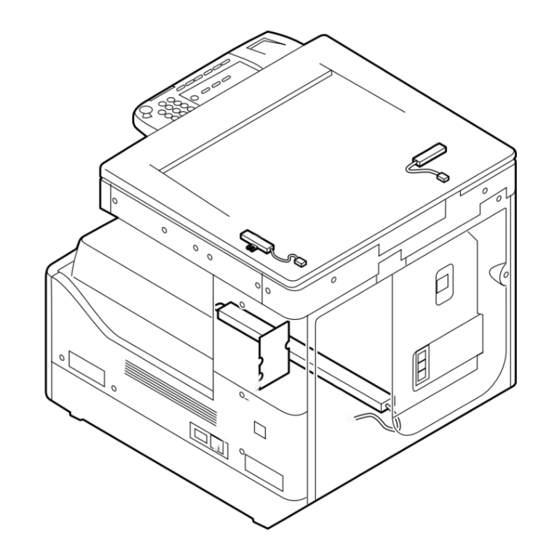
Chapter 1 1.2 Product Specifications 1.2.1 Names of Parts 1.2.1.1 External View (iR2020/iR2020J) 0011-1098 iR2020 / [14] [13] [12] [11] [15] [10] [16] [18] [17] F-1-10 Copyboard cover (*1) [10] Left door Reader front cover [11] Left cover (rear) Control panel [12] Reader left cover Delivery tray... -
Page 40: External View (Ir2020I)
Chapter 1 1.2.1.2 External View (iR2020i) 0012-6002 iR2020i [13] [14] [12] [11] [15] [10] [17] [16] F-1-11 DADF [10] Left door Reader front cover [11] Left cover (rear) Control panel [12] Reader left cover Delivery tray [13] Reader right cover Front cover [14] Reader rear cover... -
Page 41: External View (Ir2016/Ir2016J)
Chapter 1 1.2.1.3 External View (iR2016/iR2016J) 0011-1099 iR2016J / iR2016 [13] [12] [11] [10] [14] [16] [15] F-1-12 Copyboard cover (*1) Left door Reader front cover [10] Left cover (rear) Control panel [11] Reader left cover Delivery tray [12] Reader right cover Front cover [13] Reader erar cover... -
Page 42: External View (Ir2016I)
Chapter 1 1.2.1.4 External View (iR2016i) 0012-6003 iR2016i [12] [13] [11] [10] [14] [16] [15] F-1-13 DADF Left door Reader front cover [10] Left cover (rear) Control panel [11] Reader left cover Delivery tray [12] Reader right cover Front cover [13] Reader rear cover Cassette 1... - Page 43 Chapter 1 Pickup roller [17] Fixing film unit Feed roller [18] Delivery roller 1-17...
-
Page 44: Using The Machine
Chapter 1 1.2.2 Using the Machine 1.2.2.1 Turning On the Power Switch (iR2020/iR2020J/iR2016/iR2016J) 0011-1100 iR2016J / iR2016 / iR2020 / / iR2016i / iR2020i The machine possesses 2 power switches: main power switch and control power switch. Normally (i.e., unless the machine is in a sleep state), the machine will be supplied with power when you turn on its main power switch. -
Page 45: Turning On The Power Switch (Ir2020I/Ir2016I)
Chapter 1 1.2.2.2 Turning On the Power Switch (iR2020i/iR2016i) 0012-6004 iR2016i / iR2020i The machine possesses 2 power switches: main power switch and control power switch. Normally (i.e., unless the machine is in a sleep state), the machine will be supplied with power when you turn on its main power switch. -
Page 46: When Turning Off The Main Power Switch (Ir2020/Ir2020J/Ir2016/Ir2016J)
Chapter 1 1.2.2.3 When Turning Off the Main Power Switch (iR2020/iR2020J/iR2016/iR2016J) 0011-1101 iR2016J / iR2016 / iR2020 / / iR2016i / iR2020i <During printing or fax data transmission/reception> Be sure to operate the main power switch while the Processing/Data lamp on the control panel is not lit. (Turning off the main switch during printing or fax data transmission/reception can erase the data being processed.) F-1-17 <During downloading>... -
Page 47: When Turning Off The Main Power Switch (Ir2020I/Ir2016I)
Chapter 1 1.2.2.4 When Turning Off the Main Power Switch (iR2020i/iR2016i) 0012-6005 iR2016i / iR2020i <During printing or fax data transmission/reception> Be sure to operate the main power switch while the Processing/Data lamp on the control panel is not lit. (Turning off the main switch during printing or fax data transmission/reception can erase the data being processed.) F-1-19 <During downloading>... -
Page 48: Control Panel (Ir2020/Ir2020J/Ir2016/Ir2016J)
Chapter 1 1.2.2.5 Control Panel (iR2020/iR2020J/iR2016/iR2016J) 0011-1103 iR2016J / iR2016 / iR2020 / [10] [11] [12] [13] [14] [15] [31] [29] [27] [25] [23] [21] [19] [17] [30] [28] [26] [24] [22] [20] [18] [16] F-1-21 Paper select key [17] ID key Paper select indicator [18]... -
Page 49: Control Panel (Ir2020I/Ir2016I)
Chapter 1 1.2.2.6 Control Panel (iR2020i/iR2016i) 0012-6007 iR2016i / iR2020i [15] [12] [10] [16] [14] [13] [11] F-1-22 Touch Panel Display Start key COPY key [10] Clear key SEND key [11] Main power indicator Reset key [12] Log IN/Out key Control panel power switch [13] Error indicator Counter Check key... -
Page 50: Common Settings (Ir2020I/Ir2016I)
Chapter 1 Additional Functions Available Settings 12. DISPLAY LANGUAGE ENGLISH(*), FRENCH, SPANISH, GERMAN, ITALIAN, DUTCH, FINNISH, PORTUGUESE, NORWEGIAN, SWEDISH, DANISH, SLOVENE, CZECH, HUNGARIAN, RUSSIAN, TURKISH, GREEK, ESTONIAN, ROMANIAN, SLOVAK, CROATIAN, BULGARIAN, CATALAN, POLISH 13. ADF DIRTY ERROR ON(*), OFF 14. INIT. COMMON SET. OFF(*), ON *: Factory default 1.2.3.2 Common Settings (iR2020i/iR2016i) -
Page 51: Timer Settings (Ir2020I/Ir2016I)
Chapter 1 *: Factory default 1.2.3.4 Timer Settings (iR2020i/iR2016i) 0012-6020 iR2016i / iR2020i T-1-3 Item Settings(*1 Indicates the default setting.) Date & Time Settings Date and Time Setting (12 digit number) Time Zone Settings: GMT -12:00 to GMT +12:00; GMT -03:00*1 Daylight Saving Time Settings: On, Off*1 Auto Sleep Time On*1 3 to 30 minutes;... -
Page 52: Report Settings (Ir2020I/Ir2016I)
Chapter 1 1.2.3.8 Report Settings (iR2020i/iR2016i) 0012-6024 iR2016i / iR2020i T-1-5 Item Settings(*1 Indicates the default setting.) Settings TX Report: On, For Error Only*1, Off Report With TX Image: On*1, Off Activity Report Auto Print: On*1, Off Send/Receive Separate: On, Off*1 RX Report: On, For Error Only, Off*1 Print List Address Book List... -
Page 53: Timer Settings (Ir2020/Ir2020J/Ir2016/Ir2016J)
Chapter 1 Item Settings(*1 Indicates the default setting.) RAW Settings Use RAW, Use Bidirectional Use PASV Mode for FTP Use PASV Mode for FTP On/Off FTP Extension FTP Extension On/Off Use HTTP Use HTTP On/Off Port Number Settings LPD, RAW, HTTP, SMTP, Receive, POP3 Receive, FTP Sending, SMTP Sending, SNMP IP Address Range Settings On/Off*1 A maximum of 4 IP addresses can be stored. -
Page 54: Report Settings (Ir2020/Ir2020J/Ir2016/Ir2016J)
Chapter 1 Item Settings(*1 Indicates the default setting.) Auto Orientation On*1, Off Standard Settings Store, Initialize Initialize Copy Settings Yes, No 1.2.3.13 Report Settings (iR2020/iR2020J/iR2016/iR2016J) 0011-1228 iR2016J / iR2016 / iR2020 / Additional Functions Available Settings 1. SETTINGS TX REPORT: PRINT ERROR ONLY(*), OUTPUT YES, OUTPUT NO RX REPORT: OUTPUT NO(*), PRINT ERROR ONLY, OUTPUT YES ACTIVITY REPORT: AUTO PRINT (ON(*), OFF), TX/RX SEPARATE (OFF(*), ON) 2. -
Page 55: Printer Settings (Ir2020I/Ir2016I)
Chapter 1 Additional Functions Available Settings 1. TRANS. ROLR CLEAN Press [OK] to start cleaning. 2. DRUM CLEANING Press [OK] to start cleaning. 3. FIX. UNIT CLEANING START CLEANING, CLEAN PAPER PRT 4. FEEDER CLEANING Set 5 sheets in the optional feeder and press [OK]. 5. - Page 56 Chapter 1 Additional Functions Available Settings 4. MANAGE USER ID OFF(*), ON 5. NETWORK SETTINGS TCP/IP SETTINGS: IP ADDRESS AUTO. (OFF(*), ON; DHCP, BOOTP, RARP), IP ADDRESS, SUBNET MASK, GATEWAY ADDRESS, USE LPD (ON(*); PORT NO., OFF), RAW SETTINGS (ON(*); PORT NO., USE BIDIRECTIONAL, OFF), USB HTTP (ON(*);...
-
Page 57: Address Book Settings (Ir2020I/Ir2016I)
Chapter 1 1.2.3.18 Address Book Settings (iR2020i/iR2016i) 0012-6039 iR2016i / iR2020i T-1-10 Item Settings(*1 Indicates the default setting.) Register Address Register New Add Fax Number: 120 characters maximum Register Name: 16 characters maximum Option: Sending Speed, Long Distance, ECM TX E-mail E-mail Address: 120 characters maximum Register Name: 16 characters maximum... -
Page 58: Cleaning (Ir2020/Ir2020J/Ir2016/Ir2016J)
Chapter 1 1.2.4.2 Cleaning (iR2020/iR2020J/iR2016/iR2016J) 0011-0420 iR2016J / iR2016 / iR2020 / The parts that should be cleaned by the customer to maintain the design performance and the cleaning method are described below. The service engineer should instruct the customer to clean the machine at regular intervals (once a month). 1. -
Page 59: Cleaning (Ir2020I/Ir2016I)
Chapter 1 F-1-26 8) Using the left and right arrow keys, select "START CLEANING". 9) Press the OK key. Cleaning will start. 4. Cleaning the Transfer Roller If the reverse side of the printed paper is stained, the transfer roller can be dirty. If the reverse side of the printed paper is stained, clean the transfer roller in the user mode. -
Page 60: Safety
Chapter 1 MEMO: The time required for cleaning is about 100 seconds. 1) Press the Additional functions key to enter the user mode. 2) Select "Adjustment/Cleaning" on the touch panel. 3) Select "Fixing Unit Cleaning" and then press [Cleaning Sheet Print]. The cleaning pattern will be printed. 4) Open the manual feed tray. -
Page 61: Handling The Laser Unit (Ir2020/Ir2020J/Ir2016/Ir2016J)
Chapter 1 CANON 30-2, SHIMOMARUKO, 3-CHOME, OHTAKU, TOKYO, 146, JAPAN. MANUFACTURED: THIS PRODUCT CONFORMS WITH DHHS RADIATION PERFORMANCE STANDARD 21CFR CHAPTER 1 SUBCHAPTER J. F-1-31 1.2.5.3 Handling the Laser Unit (iR2020/iR2020J/iR2016/iR2016J) 0010-8955 iR2016J / iR2016 / iR2020 / The laser scanner unit emits invisible laser light inside it. If exposed to laser light, the human eye can irreparably be damaged. Never attempt to disassemble the laser scanner unit. -
Page 62: Safety Of Toner
Chapter 1 F-1-33 1.2.5.5 Safety of Toner 0010-8954 iR2016J / iR2016 / iR2020 / / iR2016i / iR2020i The machine's toner is a non-toxic material made of plastic, iron, and small amounts of dye. Do not throw toner into fire. It may cause explosion. Toner on Clothing or Skin 1. -
Page 63: Product Specifications
Toner type magnetic negative toner Original type sheet, book Maximum original size A3/LDR Original size detection function by reflection type sensor (iR2020 series only) Sleep mode Option See the system configuration chart. Operating environment 15 to 27.5 deg C (temperature range) -
Page 64: Function List
Chapter 1 Dimensions iR2020/iR2020J: 622 mm x 633.4 mm x 665.4 mm (WxDxH) iR2016/iR2016J: 622 mm x 633.4 mm x 580.4 mm (WxDxH) iR2020i: 622 mm x 668 mm x 757 mm (WxDxH) iR2016i: 622 mm x 668 mm x 672 mm (WxDxH) Weight iR2020/iR2020J: approx. -
Page 65: Printing Speed (Ir2020I)
Chapter 1 Paper size Single-sided Casette feed Manual feed Envelope Monarch COM10 ISO-B5 ISO-C5 Supplement: - The above copy speed does not change if magnification is changed. - The above copy speed does not change irrespective of whether paper is supplied from the upper/lower cassette, the manual feed tray, or from the cassette feeding module. -
Page 66: Printing Speed (Ir2016/Ir2016J)
Chapter 1 Paper size Single-sided Casette feed Manual feed Bond paper STMT STMTR LTRR Envelope Monarch COM10 ISO-B5 ISO-C5 Postcard Postcard Double postal card 4-plane post card T-1-14 Paper size Double-sided Casette feed Manual feed Plain paper STMT STMTR LTRR Supplement: - The above copy speed does not change irrespective of whether paper is supplied from the upper/lower cassette, the manual feed tray, or from the cassette feeding module. -
Page 67: Printing Speed (Ir2016I)
Chapter 1 T-1-15 Paper size Single-sided Cassette feed Manual feed Plain paper STMT STMTR LTRR Heavy paper 1/2 12(10) 12(10) (Heavy paper 3) 13(11) 13(11) 11(7) 12(10) 12(10) 9(6) 9(6) 10(8) 10(8) 8(6) 8(6) 8(7) 8(7) STMT 11(7) 11(7) STMTR 9(6) 12(10) 11(10) - Page 68 Chapter 1 T-1-16 Paper size Single-sided Casette feed Manual feed Plain paper STMT STMTR LTRR Heavy paper(81 to 12(10) 12(10) 105g/m2) 13(11) 13(11) (Heavy paper(106 10(7) to 128g/m2) 12(10) 12(10) 9(6) 9(6) 10(8) 10(8) 8(7) 8(7) STMT 11(7) 11(7) STMTR 10(7) 13(11) 12(10)
-
Page 69: Types Of Paper
Chapter 1 T-1-17 Paper size Double-sided Casette feed Manual feed Plain paper STMT STMTR LTRR Supplement: - The above copy speed does not change irrespective of whether paper is supplied from the upper/lower cassette, the manual feed tray, or from the cassette feeding module. - Page 70 Chapter 1 1-44...
-
Page 71: Chapter 2 Installation
Chapter 2 Installation... - Page 73 Contents Contents 2.1 Making Pre-Checks................................2-1 2.1.1 Selecting the Site of Installation ..............................2-1 2.1.2 Before Starting the Work (230V EUR) ............................2-1 2.1.3 Before Starting the Work (230V EUR) ............................2-3 2.2 Unpacking and Installation ............................2-5 2.2.1 Unpacking and Removing the Packaging Materials ........................2-5 2.2.2 Unpacking and Removing the Packaging Materials ........................
-
Page 75: Making Pre-Checks
Chapter 2 2.1 Making Pre-Checks 2.1.1 Selecting the Site of Installation 0011-1068 iR2016J / iR2016 / iR2020 / / iR2016i / iR2020i Select the site of installation against the following requirements; if possible, visit the user's before delivery of the machine: 1) There must be a power outlet properly grounded and rated as indicated (-/+10%) for exclusive use by the machine. - Page 76 Chapter 2 2) The machine weighs a maximum of about 46 kg. Be sure to work in a group of 2 persons when lifting it. 1-2 Checking the Contents Check to be sure that none of the following contents is missing: 11 17 Set the size detector lever to the Set the size detector lever to the...
- Page 77 Chapter 2 2.1.3 Before Starting the Work (230V EUR) 0012-6997 iR2016i / iR2020i 1-1 Points to Make Before Installation Be sure to go through the following before starting the work: 1) If you are installing the machine after moving it from a cold to warm location, be sure to leave the machine unpacked for at least 2 hours so that the machine is fully used to the site temperature, thus avoiding image faults caused by condensation.
- Page 78 Chapter 2 [13] [14] [12] [11] [15] [10] [17] [16] F-2-6 DADF [10] Left door Reader front cover [11] Left cover (rear) Control panel [12] Reader left cover Delivery tray [13] Reader right cover Front cover [14] Reader rear cover Cassette 1 [15] Rear cover...
-
Page 79: Unpacking And Installation
Chapter 2 2.2 Unpacking and Installation 2.2.1 Unpacking and Removing the Packaging Materials 0011-1070 iR2016J / iR2016 / iR2020 / 1) Unpack the machine and remove vinyl, cushioning materials, and tape. 2) Hold the handles [1] of the machine together with one or more persons and take it out. - Page 80 Chapter 2 F-2-13 F-2-10 6) Turn the developer pressure release lever [1] counterclockwise, and then 3) Open the packaging bag of the new drum unit, take the new drum out of close the left door [2]. it, and then remove packing tape. The drum unit for Asia/Oceania is provided with pressure release hooks [1].
-
Page 81: Installing The Toner Bottle
Chapter 2 2.2.4 Installing the Toner Bottle 5) Turn the toner cartridge in the direction of the arrow until it stops. 0011-1072 iR2016J / iR2016 / iR2020 / If the machine is installed in a low-temperature, low-humidity place, the im- age density may be slightly lower than usual on the first approx. - Page 82 Chapter 2 F-2-24 2) Open the front cover [1]. F-2-28 6) Close the front cover. F-2-25 3) Insert the toner bottle. F-2-29 <Going through the Developer Idling Mode> When installing the machine in a low-temperature, low-humidity environ- ment, go through the developer idling mode before installing the toner bottle in order to prevent the density from becoming low on the first approx.
-
Page 83: Setting The Cassettes
Chapter 2 2.2.6 Setting the Cassettes 0011-1073 iR2016J / iR2016 / iR2020 / / iR2016i / iR2020i 1) Holding the knob [1] at the center of the cassette, draw out the cassette [2] until it stops. F-2-33 5) Turn the paper trailing edge registration plate [1] to the left to remove it. Re-attach it to fit to the size of the paper to be loaded. -
Page 84: Attaching The Ferrite Core
Chapter 2 F-2-39 2.2.8 Attaching the Ferrite Core 0012-6451 iR2016i / iR2020i F-2-36 8) Affix the caution sheet printed in an appropriate language. 1) Attach the ferrite core [2] to the user's USB cable, and then connect the USB cable to the USB port of the host machine. To reduce noise, attach the ferrite core as close to the USB port of the host machine as possible. -
Page 85: Setting The Country/Region
Chapter 2 - Check the printed images at all preset magnifications. - Check whether the document is copied normally on the specified number of sheets. 2.2.10 Setting the Country/Region 0011-1077 iR2016J / iR2016 / iR2020 / 1) Press the following keys to display the service mode screen: Additional Functions Key >... -
Page 86: Setting The Date And Time
Chapter 2 2.2.13 Setting the Date and Time 0012-6455 iR2016i / iR2020i 1) Press key to display the user mode screen. 2) Select "TIMER SETTINGS" and then press the OK. 3) Select "DATE&TIME SETTING", and then press the OK. The set date and time appears. - Page 87 Chapter 2 If the machine supports a network feature, check the network connection fol- lowing the procedure below. 1) Press the following keys to display the service mode screen: Additional Functions Key > 2 Key > 8 Key > Additional Functions Key 2) Select "# REPORT"...
-
Page 88: Checking The Network Connection
Chapter 2 2.3.2 Checking the Network Connection 0012-7020 iR2016i / iR2020i If the machine supports a network feature, check the network connection fol- lowing the procedure below. 1) Press the following keys to display the service mode screen: > 2 Key > 8 Key > 2) Select "# REPORT"... -
Page 89: Flow Of Accessory Installation
Chapter 2 2.4 Flow of Accessory Installation 2.4.1 Flow of Accessary Installation 0012-6980 iR2016J / If you are going to install any accessory after installing the host machine, follow the following flow of work so that the work will become effective. Host machine installation Power supply kit installation Cassette feeding module installation... -
Page 90: Flow Of Accessary Installation
Chapter 2 2.4.2 Flow of Accessary Installation 0012-6981 iR2016 / iR2020 If you are going to install any accessory after installing the host machine, follow the following flow of work so that the work will become effective. Host machine installation Power supply kit installation (*1) Cassette feeding module installation Duplex unit installation... -
Page 91: Flow Of Accessary Installation
Chapter 2 2.4.3 Flow of Accessary Installation 0012-6982 iR2016i / iR2020i If you are going to install any accessory after installing the host machine, follow the following flow of work so that the work will become effective. Host machine installation Cassette feeding module installation Duplex unit installation (*1) Additional finisher tray installation... -
Page 92: Installing The Card Reader
Chapter 2 2.5 Installing the Card Reader 2.5.1 Points to Note 0011-1080 iR2016J / iR2016 / iR2020 / / iR2016i / iR2020i When installing the card reader, the card reader attachment-D1 is required. 2.5.2 Checking the Contents 0011-1081 iR2016J / iR2016 / iR2020 / / iR2016i / iR2020i <Card reader-E1>... -
Page 93: Installation Procedure
Chapter 2 Harness cover (base + lid) 3 pcs. Repeating harness B 1 pc. Edge saddle 1 pc. TP screw 2 pcs. Binding screw (M4x6) 4 pcs. 2.5.3 Installation Procedure 0011-1082 iR2016J / iR2016 / iR2020 / / iR2016i / iR2020i 1) Turn off the main power switch [1] of the host machine and disconnect the power plug [2] from the outlet. - Page 94 Chapter 2 When removing the harness [1] through the opening in the card reader mount, take care not to cut or damage it. F-2-55 MEMO: The removed card reader mount is no longer necessary. 5) Insert the card reader [2] harness and ground cable into the hole in the supplied card reader mount [1]. Using the screw [3] removed in step 1, secure the card reader to the card reader mount.
- Page 95 Chapter 2 F-2-58 8) Secure the repeating harness B [1] with the wire saddle [2]. F-2-59 9) Remove the two blind seals [1] from the reader left cover. F-2-60 10) Using the two supplied TP screws (M4x16), attach the card reader to the reader. When tightening the screws, take care not to damage the repeating harness B.
- Page 96 Chapter 2 F-2-62 Route the repeating wire B [1] as shown below. F-2-63 12) Using the supplied binding screw (M4x6), secure the card reader cover [2]. F-2-64 13) Affix the two supplied harness covers (bases) at the right rear of the machine with it aligned with the bottom line of the reader. F-2-65 14) Affix the supplied harness cover (base) [1] at the back of the machine with it aligned with the bottom line of the reader.
- Page 97 Chapter 2 F-2-66 15) Connect the connector of the repeating harness B [1] to the connector J317 [2] on the image processor PCB. F-2-67 16) Using the supplied binding screw (M4x6) [1], secure the repeating harness B clamp [2]. F-2-68 17) Using the three harness covers (lids) [2], secure the repeating harness B [1] to the harness covers (bases).
-
Page 98: Registering The Card Ids
Chapter 2 F-2-70 19) Attach the rear cover with the repeating harness B routed through the cut portion of the rear cover. F-2-71 2.5.4 Registering the Card IDs 0011-1083 iR2016J / iR2016 / iR2020 / After installing the card reader-E1, register the card numbers to be used in the service mode of the iR body. If they are not registered, cards will not be recognized when inserted. -
Page 99: Registering The Card Ids
Chapter 2 2.5.5 Registering the Card IDs 0012-7190 iR2016i / iR2020i After installing the card reader-E1, register the card numbers to be used in the service mode of the iR body. If they are not registered, cards will not be recognized when inserted. -
Page 100: Installing The Heater Pcb
Chapter 2 2.6 Installing the Heater PCB 2.6.1 Preparing the parts 0011-3362 iR2016J / iR2016 / iR2020 / / iR2016i / iR2020i 1) Prepare the following parts. F-2-74 Heater PCB unit 1 pc. Heater switch harness 1 pc. Cassette heater harness 1 pc. - Page 101 Chapter 2 F-2-75 1) Open the front cover [1]. F-2-76 2) Remove the four screws [1], and then detach the rear cover [2]. 3) Remove the five screws [3]. Remove the two hooks [4], and then detach the lower-right cover [5]. 4) Remove the screw [6], and then detach the upper-right cover [7].
-
Page 102: Installing The Heater Pcb
Chapter 2 F-2-78 6) Using a nipper or the like, cut out the face plate [2] (used to install a heater switch) on the lower-right cover [1]. F-2-79 2.6.3 Installing the Heater PCB 0011-3365 iR2016J / iR2016 / iR2020 / / iR2016i / iR2020i 1) Install the heater PCB unit [2] using the two supplied TP screws (M3x8) [1]. - Page 103 Chapter 2 F-2-80 3) Install the edge saddle (large) [1] and connect one heater switch harness [2] to the connector (J1901) on the heater PCB. Route the other harness [3] to the front of the host machine through the saddle. F-2-81 4) Install the edge saddle (small) [1] on the power supply unit at the front of the host machine, and then connect the header switch harness [2] (routed to the front of the host machine) to the connector (J15) on the power supply PCB through the edge saddle.
- Page 104 Chapter 2 F-2-82 5) Install the four clamps [1] on the back of the host machine. 6) Connect the cassette heater harness [2] to the connector (J1905) on the heater PCB unit, install the reuse band [3], and then pass the harness through the clamps installed in step 5).
- Page 105 Chapter 2 F-2-85 10) Install the delivery tray. (2 screws) When reinstalling the delivery tray, be careful not to damage the paper holder. 11) Attach the upper-right cover of the host machine. (1 screw) 12) Attach the lower-right cover of the host machine. (5 screws) 13) Attach the rear cover of the host machine.
-
Page 106: Installing The Reader Heater
Chapter 2 2.7 Installing the Reader Heater 2.7.1 Preparing the parts 0011-3368 iR2016J / iR2016 / iR2020 / / iR2016i / iR2020i Before installing, make sure the heater PCB has been installed. 1) Prepare the following parts. F-2-86 Reader heater 2 pcs. - Page 107 Chapter 2 F-2-87 1) Open the front cover [1]. F-2-88 2) Remove the four screws [1], and then detach the rear cover [2]. 3) Remove the five screws [3]. Remove the two hooks [4], and then detach the lower-right cover [5]. 4) Remove the screw [6], and then detach the upper-right cover [7].
- Page 108 Chapter 2 F-2-90 6) Remove the core [1] and the flexible cable holder [2] at the back of the host machine. Disconnect the two reader flexible cables [3]. 7) Disconnect the harness [4] from the four wire saddles [5]. 8) Remove the two screws [6], and then detach the flexible cable cover [7]. F-2-91 The reader flexible cables are stuck to the flexible cable cover, so do not pull the cover forcibly.
- Page 109 Chapter 2 F-2-92 10) Pass the heater harness [1] though the harness guide [2] with the clamp [3] of the heater harness aligned with the notch [4] in the harness guide. F-2-93 11) Remove the four screws [1], and then the metal plate [2]. 2-35...
-
Page 110: Removing Reader Components
Chapter 2 F-2-94 12) Secure the harness guide [1] to the rear bottom of the reader together with the heater harness [2]. 13) Connect the heater connector (right) [3]. 14) Install the wire saddle [4], and then pass the heater harness [2] through it. 15) Connect the heater connector (left) [5]. -
Page 111: Removing Parts At The Left Of The Reader
Chapter 2 F-2-96 2.7.4 Removing Parts at the Left of the Reader 0011-3376 iR2016J / iR2016 / iR2020 / / iR2016i / iR2020i The work procedure for removing the parts at the left of the reader differs between the machine with a copyboard cover and the machine with a DADF. Follow the appropriate procedure. - Page 112 Chapter 2 F-2-98 b. Machine with a DADF 1) Remove the two screws [1], and then detach the stream reading glass holder [2]. 2) Remove the stream reading glass [3]. F-2-99 Mount the stream reading glass with the notch [1] of the sheet material affixed to the glass is at the front left. F-2-100 3) Remove the screw [1], and then remove the jump board [2].
-
Page 113: Installing The Reader Heater
Chapter 2 F-2-101 4) Remove the screw [1], and then the stay [2]. F-2-102 2.7.5 Installing the Reader Heater 0011-3385 iR2016J / iR2016 / iR2020 / / iR2016i / iR2020i 1) Pull the front side [1] of the drive belt in the direction of the arrow to move the contact sensor [2] to the center Do not touch the top surface of the contact sensor. - Page 114 Chapter 2 F-2-104 4) Attach the heater cover [1] using a screw [2]. F-2-105 5) Install the reader heater [1] using a screw [2]. Connect the connector [3] of the heater. F-2-106 6) Attach the heater cover [1] using a screw [2]. 2-40...
- Page 115 Chapter 2 F-2-107 7) Reinstall the parts at the left of the reader. 8) Attach the front cover of the reader. (2 screws) 9) Install the copyboard glass. 10) Install the right glass holder of the reader. (2 screws) 11) Attach the rear left cover of the host machine. (3 screws) 12) Attach the upper-right cover of the host machine.
-
Page 116: Installing The Cassette Heater
Chapter 2 2.8 Installing the Cassette Heater 2.8.1 Preparing the parts 0011-3181 iR2016J / iR2016 / iR2020 / / iR2016i / iR2020i Before installing the cassette heater, make sure the heater PCB has been installed. 1) Prepare the following parts. F-2-108 Cassette heater 1 pc. - Page 117 Chapter 2 F-2-111 When installing the cassette heater unit, make sure that harness is not pinched. 2) Secure the cassette heater [2] using a screw [1]. 3) Connect one harness [3] to the cassette heater harness [4]. 4) Place the other harness [5] at the position shown below. Connect this connector to the heater of the cassette when connecting the cassette heater to the cassette at the second or lower stage.
- Page 118 Chapter 2 F-2-113 When installing the heater for the cassette at the second or lower stage, detach the rear cover of the cassette and follow the procedure mentioned in this procedural manual. 2-44...
-
Page 119: Installing The Control Card Cable
Chapter 2 2.9 Installing the Control Card Cable 2.9.1 Preparing the parts 0012-4187 iR2016J / iR2016 / iR2020 / / iR2016i / iR2020i 1) Prepare the following parts. F-2-118 5) Using a nipper, remove the precut portion [1] of the rear cover as shown below. - Page 120 Chapter 2 2-46...
-
Page 121: Chapter 3 Main Controller
Chapter 3 Main Controller... - Page 123 Contents Contents 3.1 Construction ...................................3-1 3.1.1 Construction and Mechanisms ..............................3-1 3.1.2 Construction and Mechanisms ..............................3-1 3.2 Construction of the Electrical Circuitry .........................3-2 3.2.1 Image Processor PCB .................................. 3-2 3.3 Image Processing ................................3-3 3.3.1 Overview of the Image Flow ............................... 3-3 3.3.2 Construction of the Image Processing Module ..........................
-
Page 125: Construction
Chapter 3 3.1 Construction 3.1.1 Construction and Mechanisms 0010-7009 iR2016J / iR2016 / iR2020 / The machine's main controller block consists of the following and has the following functions: T-3-1 Item Description Image Processor PCB Controls system operation, memory, printer unit output, image processing, printer unit image input processing, card printer unit interface, fax image processing, etc. -
Page 126: Construction Of The Electrical Circuitry
Chapter 3 Reader Unit Image Processor PCB USB port DC controller PCB Flash ROM Image memory (SDRAM) F-3-2 3.2 Construction of the Electrical Circuitry 3.2.1 Image Processor PCB 0010-6854 iR2016J / iR2016 / iR2020 / / iR2016i / iR2020i The following is a diagram showing the major control mechanisms of the Image Processor PCB according to connectors: J317 J320 J300... -
Page 127: Image Processing
Chapter 3 Connector Description J308 Reader ADF connection slot J309 Reader Book connection slot J310 Power supply connection slot J312 SERIAL PCB connection slot J314 DC controller PCB connection slot J315 SOFT ID PCB connection slot J316 SOFT counter PCB connection slot J317 New Card Reader connection slot J318... -
Page 128: Reader Unit Input Image Processing
Chapter 3 Reader Unit Reader controller PCB Reader unit input image processing block Image Processor PCB Processes the image data Printer unit output image read by the reader unit. processing block Processes image data for DC controller PCB output to the printer unit. SDRAM - image memory - program (temporary storage) -
Page 129: Compressio/ Extesion/ Editing Block
Chapter 3 Image processor PCB PDL image Reader image processing block processing block SDRAM Enlargement/ Compression reduction Expansion Rotation Integration to printer unit output image processing block F-3-7 3.3.5 Compressio/ Extesion/ Editing Block 0010-8691 iR2016J / Here, image data is processed for compression, extension, and editing. Image processor PCB Reader image processing block SDRAM... -
Page 130: Flow Of Image Data
Chapter 3 Image processor PCB Compression/expansion/editing block Binary density conversion Enlargement/reduction Smoothing To DC controller PCB F-3-9 3.4 Flow of Image Data 3.4.1 Flow of Image Data According to Copy Functions 0010-8689 iR2016J / iR2016 / iR2020 / / iR2016i / iR2020i The following is the flow of image data when the Copy Function is in use: Reader unit Image processor PCB... -
Page 131: Flow Of Image Data For The Fax Transmission
Chapter 3 Reader unit mage processor PCB Image processing block for reader unit SDRAM Data expansion USB1.1 Data rotation Resolution conversion Ethernet port (compression data) To network F-3-11 3.4.3 Flow of Image Data for the Fax Transmission 0010-8696 iR2016 / iR2020 / iR2016i / iR2020i The following is the flow of image data when the fax transmission function is in use: Reader unit Image processor PCB... -
Page 132: Flow Of Image Data For The Pdl Function
Chapter 3 Super G3 Fax Board Image processor PCB Image processing block for fax SDRAM Data rotation Data compression Data expansion Image processing block for printer unit DC controller PCB F-3-13 3.4.5 Flow of Image Data for the PDL Function 0010-8699 iR2016 / iR2020 / iR2016i / iR2020i The following is the flow of image data when the PDL function is in use:... -
Page 133: Parts Replacement Procedure
Chapter 3 3.5 Parts Replacement Procedure 3.5.1 Main Controller PCB 3.5.1.1 Removing the Rear Cover 0010-8701 iR2016J / iR2016 / iR2020 / / iR2016i / iR2020i 1) Remove the four screws [1], and then detach the rear cover [2]. F-3-18 3.5.1.5 Removing the LAN Cover 0010-8716 iR2016 / iR2020 / iR2016i / iR2020i... -
Page 134: Removing The Ip Cover
Chapter 3 1) Remove a connector [1] of IP-LAN cable and a cable clamp [2]. F-3-25 F-3-21 2) Release SOFT ID cable [1] from the cable clamp [2]. 3) Open a core [1]. F-3-22 4) Remove the two screws [1], and then detach the flexible cable guide [2]. F-3-26 3) Release a claw [1] of cable guide and detach the cable guide [2] upward. -
Page 135: Removing The Image Processor Pcb
Chapter 3 F-3-29 6) Remove the 10 screws [1], and then detach the IP cover [2]. F-3-32 3.5.1.9 Procedure after Replacing the Image Processor PCB (iR2020/iR2020J/iR2016/iR2016J) 0011-3396 iR2016J / iR2016 / iR2020 / If you have replaced the image processor PCB with a new one, perform the following operations: - Using the service support tool, download the latest firmware (System/ Boot). -
Page 136: Sdram
Chapter 3 After completion of automatic adjustment, "OK" is displayed. - Read position adjustment (Stream reading: Only when the ADF is installed) 1) Enter the service mode. Sequentially press the Additional functions key, 2 key, 8 key, and Additional functions key on the operation panel. 2) Press the arrow key on the touch panel to display "TEST MODE". -
Page 137: Chapter 4 Original Exposure System
Chapter 4 Original Exposure System... - Page 139 Contents Contents 4.1 Construction ...................................4-1 4.1.1 Specifications, Control Methods, and Functions (iR2020/iR2020J/iR2020i) ................4-1 4.1.2 Specifications, Control Methods, and Functions (iR2016/iR2016J/iR2016i) ................4-1 4.1.3 Major Components (iR2020/iR2020J/iR2020i)........................... 4-1 4.1.4 Major Components (iR2016/iR2016J/iR2016i)........................... 4-2 4.1.5 Control System Configuration (iR2020/iR2020J/iR2020i) ......................4-3 4.1.6 Control System Configuration (iR2016/iR2016J/iR2016i) ......................
- Page 140 Contents 4.4.3.3 Removing the Right Cover (Upper)................................4-20 4.4.3.4 Removing the Left Cover (Rear) .................................. 4-21 4.4.3.5 Removing the Reader Rear Cover ................................4-21 4.4.3.6 Removing the Scanner Motor ..................................4-21 4.4.4 Contact sensor.................................... 4-21 4.4.4.1 Removing the Rear Cover..................................... 4-21 4.4.4.2 Removing the Right Cover (Lower) ................................
-
Page 141: Construction
Chapter 4 4.1 Construction 4.1.1 Specifications, Control Methods, and Functions (iR2020/iR2020J/iR2020i) 0010-4242 iR2020 / / iR2020i Major specifications, control methods, and functions of the original exposure system are summarized below. T-4-1 Item Function/Method Exposure light source Original scan In BOOK mode: Original scan is performed by moving the contact image sensor (CIS). When ADF is used: Original stream reading is performed with the contact image sensor (CIS) fixed. -
Page 142: Major Components (Ir2016/Ir2016J/Ir2016I)
Chapter 4 [12] [11] [10] F-4-1 T-4-3 Component Function/Specification Copyboard cover open/close SR402 Photo interrupter: Detects the copyboard cover open/ sensor (Rear: SR402) close status. Starts detecting the original size when the copyboard cover angle is 30 deg. Reader controller PCB Controls drive of the reader unit and image processing. -
Page 143: Control System Configuration (Ir2020/Ir2020J/Ir2020I)
Chapter 4 Component Function/Specification Reader controller PCB Controls drive of the reader unit and image processing. Reader motor M401 Pulse motor: Controls drive of the carriage. Reader heater*1 Prevents condensation inside the original glass. Contact image sensor (CIS) Uses LEDs for indirect exposure (LED + Photoconductor) CISHP sensor SR401... -
Page 144: Reader Controller Pcb (Ir2020/Ir2020J/Ir2020I)
Chapter 4 [11] [10] F-4-4 [1] Printer main body (Connected to the image processor PCB) [2] Connected to ADF [3] Connected to the power supply PCB [4] Reader motor drive control [5] Reader motor (M401) [6] Reader controller PCB [7] Contact image sensor [8] Image signal [9] CISHP sensor (PS503) [10] Copyboard cover open/close sensor (Front: SR403) -
Page 145: Basic Sequence
Chapter 4 Jack No. Function J406 Connected to the contact image sensor (CIS) HP sensor. J407 Connected to the original sensor 1 and original sensor 2. J408 Connected to the contact image sensor (CIS). J409 Connected to the reader motor. J410 Supplies power to the ADF. -
Page 146: Basic Sequence After Depression Of Start Key (Book Mode, One Sheet Of Original)
Chapter 4 Main power switch SREADY STBY Reader motor (M401) CISHP sensor (SR401) Shading Shading position position : Forward movement : Backward movement F-4-7 CISHP sensor Shading Leading edge position of original 1. CIS position check F-4-8 4.2.2 Basic Sequence after Depression of Start Key (Book mode, One Sheet of original) 0010-4247 iR2016J / iR2016 / iR2020 / / iR2016i / iR2020i Black shading/White shading... -
Page 147: Various Control
Chapter 4 Black shading/White shading Start key STBY SCRW SCFW STBY Reader motor (M401) CISHP sensor (SR401) Shading Shading Stream reading Trailing edge position position position of original : Forward movement : Backward movement F-4-11 CS HP sensor Original glass reading start Stream reading Shading... -
Page 148: Reader Motor Control
Chapter 4 4.3.1.2 Reader Motor Control 0010-4250 iR2016J / iR2016 / iR2020 / / iR2016i / iR2020i The reader motor driver controls rotation/stop and rotational direction/speed of the reader motor based on the signals from IC2. Reader controller PCB 3.3V +24V RTP3APWN J409... -
Page 149: Analog Control Performed By The Cis (Ir2020/Ir2020J/Ir2016/Ir2016J)
Chapter 4 Image read line Light guide LED (R/G/B) Original glass Rod lens array Scan direction CMOS sensor array LED (R/G/B) Light guide Rod lens array Light guide F-4-16 4.3.2.2 Analog Control Performed by the CIS (iR2020/iR2020J/iR2016/iR2016J) 0010-4252 iR2016J / iR2016 / iR2020 / The flow of analog image processing performed by the contact image sensor (CIS) is as follows: The light reflected by the original is collected by the rod lens array. -
Page 150: Analog Control Performed By The Cis (Ir2020I/Ir2016I)
Chapter 4 4.3.2.3 Analog Control Performed by the CIS (iR2020i/iR2016i) 0012-6047 iR2016i / iR2020i The flow of analog image processing performed by the contact image sensor (CIS) is as follows: The light reflected by the original is collected by the rod lens array. - The light is received by the CMOS sensor array. -
Page 151: Outline Of Original Size Detection
Chapter 4 AB-Configration Horizontal scan direction Upper left corner Index plate of original Original sensor 3 Original sensor 4 Original sensor 1 Original sensor 2 Inch-Configration Horizontal scan direction Upper left corner of original Original sensor 3 Original sensor 5 STMT-R LTR-R Original sensor 1... -
Page 152: Dirt Sensor Control
Chapter 4 Original sensor 3 Original sensor 4 Original (A4R) Original sensor 1 Original sensor 2 Original sensor 3/4 Original sensor 1/2 F-4-22 4) The copyboard cover is closed (at an angle of more than 5 deg but less than 30 deg) Original sensor: Turns on and original size identification process 2 is performed. - Page 153 Chapter 4 Main power Start key switch WMUPR STBY SCAN SCAN Dust detection control Dust detection control Dust detection control F-4-26 [Description of Control] - At job end (Dust detection) The contact image sensor (CIS) checks the light reflected by the ADF platen roller surface at the read position for presence/absence of dust. After completion of a job, dust detection is performed maximum six times in 3 point of A, B and C.
-
Page 154: Image Processing
Chapter 4 Platen roller 0.5mm 0.5mm A B C Stream reading Lens glass Contact image sensor (CIS) F-4-28 4.3.6 Image Processing 4.3.6.1 Outline 0010-4258 iR2016J / iR2016 / iR2020 / / iR2016i / iR2020i Major specifications and functions of the image processing system are as follows: T-4-9 - CMOS sensor Number of lines: 1... -
Page 155: Cmos Sensor Drive
Chapter 4 Contact image sensor (CIS) CMOS sensor (1 line) Reader controller PCB Analog image signal CMOS sensor control signal CMOS sensor Gain drive control correction data Serial Analog image communication Target processing value Digital - Gain correction conversion image J309 - Offset correction Digital image... -
Page 156: Shading Correction
Chapter 4 4.3.6.7 Shading Correction 0010-4264 iR2016J / iR2016 / iR2020 / / iR2016i / iR2020i The machine performs shading correction for each scan. It measures the density of the standard white plate, and compares the measured value with the target value stored in the shading correction circuit to use the difference between the two as the shading correction value. -
Page 157: Parts Replacement Procedure
Chapter 4 4.4.1.2 Procedure after Replacing the Copyboard Glass (iR2020i/iR2016i) 4.4 Parts Replacement Procedure 0012-6054 iR2016i / iR2020i 4.4.1 Copyboard glass After replacing the copyboard glass, enter the correction values (X, Y, Z) of the standard white plate which are indicated on the back of the new copy- 4.4.1.1 Removing the Copyboard glass board glass in the service mode. -
Page 158: Removing The Right Cover (Lower)
Chapter 4 F-4-39 4.4.2.2 Removing the Right Cover (Lower) 0010-6090 iR2016J / iR2016 / iR2020 / / iR2016i / iR2020i F-4-42 1) Open the front cover. 4.4.2.5 Removing the Reader Rear Cover 2) Remove the five screws [1]. Remove the two hooks [2], and then detach 0010-6093 the right cover (lower) [3]. -
Page 159: Removing The Copyboard Glass
Chapter 4 F-4-48 4.4.2.7 Removing the Reader Controller PCB 0010-4300 iR2016J / iR2016 / iR2020 / / iR2016i / iR2020i F-4-45 4.4.2.6 Removing the Copyboard glass MEMO: This machine stores adjustment values in the image processor PCB, not the 0010-6094 iR2016J / iR2016 / iR2020 / / iR2016i / iR2020i reader controller PCB. -
Page 160: Scanner Motor
Chapter 4 F-4-52 6) Go to the back of the machine, and then disconnect the four connectors [1] from the reader controller PCB. 7) Remove the harness from the edge saddle/clamp [2]. 8) Remove the flexible cable holder [3], and then disconnect the two flexible F-4-55 cables [4]. -
Page 161: Removing The Left Cover (Rear)
Chapter 4 F-4-58 4.4.3.4 Removing the Left Cover (Rear) 0010-6098 iR2016J / iR2016 / iR2020 / / iR2016i / iR2020i F-4-61 1) Remove the three screws [1], and then detach the left cover (rear). When installing the ADF harness [4], fit the harness band [5] in the groove in the reader rear cover. -
Page 162: Removing The Right Cover (Lower)
Chapter 4 F-4-64 4.4.4.2 Removing the Right Cover (Lower) 0010-6101 iR2016J / iR2016 / iR2020 / / iR2016i / iR2020i F-4-67 1) Open the front cover. 4.4.4.5 Removing the Reader Rear Cover 2) Remove the five screws [1]. Remove the two hooks [2], and then detach 0010-6104 the right cover (lower) [3]. -
Page 163: Removing The Copyboard Glass
Chapter 4 F-4-73 4.4.4.7 Removing the Contact Image Sensor (CIS) 0010-4307 iR2016J / iR2016 / iR2020 / / iR2016i / iR2020i F-4-70 1) Pull the drive belt (front) [1] in the direction of the arrow to move the 4.4.4.6 Removing the Copyboard glass contact sensor [2] to the position shown below. -
Page 164: Procedure After Replacing The Cis (Ir2020I/Ir2016I)
Chapter 4 2) Using the arrow keys on the operation panel, display "TEST MODE". 3) Press the OK key. 4) Press the 2 key. "SCAN TEST" appears. 5) Press the 1 key. After completion of the above steps, contact sensor output correction will be performed and parameters will be set automatically. -
Page 165: Removing The Copyboard Cover Open/Close Sensor (Front/Rear)
Chapter 4 remove the copyboard glass [3]. F-4-85 F-4-82 When removing the copyboard glass, take care not to touch the When installing the ADF harness [4], fit the harness band [5] in the following: groove in the reader rear cover. - Glass surface - Standard white plate 5) Remove the four screws [1], and then detach the reader rear cover [2]. -
Page 166: Removing The Contact Sensor Hp Sensor
Chapter 4 F-4-88 - When removing the ADF reading glass, take care not to touch the glass surface. Dirt on these parts can show up as white/black lines in the image. If dirt is found, remove it with lint-free paper moistened with alcohol. - When installing the ADF reading glass, position the cut portion [1] of the ADF reading glass sheet at the front-left corner. -
Page 167: Removing The Original Sensor (Vertical Scan Direction) (Ir2020/Ir2020J/Ir2020I)
Chapter 4 F-4-95 4) Disconnect the connector [1], and then remove the harness from the edge saddle/clamp [2]. 5) Remove the three screws [3], and then remove the original sensor (vertical scan direction) [4] together with the mount. F-4-92 F-4-96 6) Disconnect the connector [1], and then remove the original sensor (vertical scan direction) [2]. -
Page 168: Reader Heater (Option)
Chapter 4 F-4-98 2) Disconnect the connector [1] from the reader controller PCB, and then F-4-101 remove the harness from the edge saddle [2]. 3) Remove the two screws [3], and then remove the original sensor [4] When removing the copyboard glass, take care not to touch the together with the mount. -
Page 169: Removing The Reader
Chapter 4 F-4-104 2) Remove the screw [1]. F-4-107 3) Disconnect the connector [2], disconnect the harness from the wire saddle [3], and then remove the reader heater (right) [4]. - When removing the ADF reading glass, take care not to touch the glass surface. - Page 170 Chapter 4 F-4-110 4) Remove the screw [1], and then detach the heater cover [2]. F-4-111 5) Disconnect the connector [1], remove the screw [2], and then remove the reader heater (left) [3]. F-4-112 4-30...
-
Page 171: Chapter 5 Laser Exposure
Chapter 5 Laser Exposure... - Page 173 Contents Contents 5.1 Construction ...................................5-1 5.1.1 Overview...................................... 5-1 5.1.2 Specifications and Control Mechanism ............................5-1 5.1.3 Specifications and Control Mechanism ............................5-1 5.1.4 Main Components ..................................5-1 5.1.5 Control System Configuration ..............................5-2 5.2 Various Controls ................................5-3 5.2.1 Controlling the Laser Activation Timing............................. 5-3 5.2.1.1 Laser Emission ON/OFF Control..................................5-3 5.2.1.2 Laser Emission ON/OFF Control..................................5-3 5.2.1.3 Horizontal Synchronization Control ................................5-4...
-
Page 175: Construction
Chapter 5 5.1 Construction 5.1.1 Overview 0010-9035 iR2016J / iR2016 / iR2020 / / iR2016i / iR2020i The laser scanner unit consists of a laser driver, scanner motor, and others. It is controlled by the signals from the DC controller PCB. The laser driver operates the laser diode to emit light in response to the laser control signals and video signals from the DC controller PCB. -
Page 176: Control System Configuration
Chapter 5 F-5-1 T-5-3 Name Function [1] Photoconductive drum Receives laser beams to form a latent image. [2] Laser mirror 1 (loop-back mirror) Reflects a laser beam toward laser mirror 2. [3] Laser mirror 2 (loop-back mirror) Reflects a laser beam toward the photoconductor drum. [4] BD PCB Generates a BD signal. -
Page 177: Various Controls
Chapter 5 DC Controller PCB Image Processor J206 J205 F-5-2 5.2 Various Controls 5.2.1 Controlling the Laser Activation Timing 5.2.1.1 Laser Emission ON/OFF Control 0010-7720 iR2016 / iR2020 / iR2016i / iR2020i The purpose of this control is to turn ON/OFF the laser diode (LD) in response to video signals. The DC controller PCB sends laser control signals (CNTRL0, CNTRL1, and CNTRL2), which are used to switch between laser driver operation modes, to the laser driver IC along with video signals (VDO1, /VDO1, VDO2, and /VDO2). -
Page 178: Horizontal Synchronization Control
Chapter 5 T-5-5 Laser control signal Laser Description status CTL2 CTL1 CTL0 Laser A Laser control OFF Laser beams can be emitted in response to video signals. APC over laser Forced stop of laser emission 5.2.1.3 Horizontal Synchronization Control 0010-7721 iR2016 / iR2020 / iR2016i / iR2020i The purpose of this control is to adjust the position where scanning starts in the horizontal direction (main scan direction) of the image with reference to the hori- zontal synchronization signal (/BD) sent from the BD sensor in the laser scanner. -
Page 179: Controlling The Laser Shutter
Chapter 5 DC Controller PCB J205 F-5-3 5.2.4 Controlling the Laser Shutter 5.2.4.1 Laser Shutter Control 0010-4807 iR2016J / iR2016 / iR2020 / / iR2016i / iR2020i When the drum unit is drawn out, the interlocked laser shutter moves down, shutting off the laser beam path. When opening of the front cover or left door is detected, the laser scanner motor and laser outputs turn off. - Page 180 Chapter 5 OPEN CLOSE F-5-4 Laser shutter control [1] Laser shutter [2] Laser mirror 1 [3] Laser mirror 2 [4] Polygonal mirror [5] Laser beam...
-
Page 181: Parts Replacement Procedure
Chapter 5 5.3 Parts Replacement Procedure 5.3.1 Laser Scanner Unit 5.3.1.1 Removing the Rear Cover 0010-6143 iR2016J / iR2016 / iR2020 / / iR2016i / iR2020i 1) Remove the four screws [1], and then detach the rear cover [2]. F-5-8 F-5-5 5.3.1.2 Removing the Right Cover (Lower) 0010-6175... -
Page 183: Chapter 6 Image Formation
Chapter 6 Image Formation... - Page 185 Contents Contents 6.1 Construction ...................................6-1 6.1.1 Specifications of Image Formation System ..........................6-1 6.1.2 Major Components of Image Formation System......................... 6-1 6.2 Image Formation Process...............................6-1 6.2.1 Image Formation Process................................6-1 6.3 Basic Sequence ................................6-2 6.3.1 Basic Sequence of Operation ............................... 6-2 6.4 Driving and Controlling the High-Voltage System .......................6-3 6.4.1 Outline......................................
-
Page 187: Construction
Chapter 6 6.1 Construction 6.1.1 Specifications of Image Formation System 0010-4265 iR2016J / iR2016 / iR2020 / / iR2016i / iR2020i T-6-1 Photosensitive drum Drum type OPC drum Drum diameter Cleaning mechanism Cleaning blade Processing speed 106.7mm/sec Primary charging Charging method Roller charging (AC + DC) ng roller diameter 14mm... -
Page 188: Basic Sequence
Chapter 6 The image formation process of this machine is composed of the following five blocks (7 steps): [1] Electrostatic latent image formation block Step 1: Primary charging (AC & Minus DC) Step 2: Laser exposure [2] Developing block Step 3: Developing (AC & Minus DC bias) [3] Transfer block Step 4: Transfer (Plus DC) Step 5: Separation (Minus DC) -
Page 189: Driving And Controlling The High-Voltage System
Chapter 6 Print command is received STBY INTR PRINT PRINT Main motor (M204) Scanner motor (M203) Primary charging AC bias Primary charging DC bias Developing AC bias Developing DC bias Transfer bias Static eliminator bias Fixing film bias F-6-4 [1] Between sheets - At the end of printing To prevent fogging of the drum, the developing DC bias is held higher than usual except during image formation. -
Page 190: Drum Unit
Chapter 6 High-voltage power DC controller supply PCB JP5/JP6 Fixing film bias J214 J100 circuit ASIC JP3/JP4 Primary bias circuit JP9/JP10 Static eliminator bias circuit Transfer bias circuit Developing bias JP7/JP8 circuit JP1/JP2 Remaining toner level detection circuit F-6-6 6.5 Drum Unit 6.5.1 Outline of the Drum Unit 6.5.1.1 Outline 0010-4275... -
Page 191: Developing Unit
Chapter 6 DC controller PCB High-voltage power supply PCB J214 Primary bias circuit J100 /PRDCPWM Compariso Primary DC bias voltage circuit detection circuit /PRDCFOT DC generation circuit JP3/JP4 Superimposition ASIC To primary /PRACFOT charging roller AC generation circuit /PRACON Comparison Primary AC bias current circuit detection circuit... -
Page 192: Toner Container
Chapter 6 DC controller High-voltage power supply PCB Developing bias circuit /DVDCPWM Comparison Developing DC bias ASIC circuit voltage detection circuit DC generation circuit /DVDCFOT JP7/JP8 Superimposition /DVACFOT To developing /DVACON AC generation circuit cylinder Developing AC bias current detection circuit TNRCHKD JP1/JP2 Remaining toner level... -
Page 193: Controlling The Transfer Bias
Chapter 6 F-6-12 6.8.2 Controlling the Transfer Bias 6.8.2.1 Transfer Roller Bias Control 0011-1657 iR2016J / iR2016 / iR2020 / / iR2016i / iR2020i A negative bias, sheet-to-sheet bias, or positive bias is applied to the transfer charging roller according to the type of sequence. The negative bias is applied at the prescribed timing to moves the toner from the transfer charging roller to the photosensitive drum for cleaning. -
Page 194: Photosensitive Drum Cleaning
Chapter 6 6.9 Photosensitive Drum Cleaning 6.9.1 Outline 0010-4292 iR2016J / iR2016 / iR2020 / / iR2016i / iR2020i Toner reaming on the photosensitive drum after image transfer is scraped by the photosensitive drum cleaner blade and is fed in the waste toner box. 6.9.2 Waste Toner Full Detection 0010-4294 iR2016J / iR2016 / iR2020 / / iR2016i / iR2020i... -
Page 195: Parts Replacement Procedure
Chapter 6 6.10 Parts Replacement Procedure 6.10.1 Drum Unit 6.10.1.1 Removing the Drum Unit 0010-6179 iR2016J / iR2016 / iR2020 / / iR2016i / iR2020i 1) Open the front cover [1]. 2) Turn the developing assembly locking lever [2] clockwise to open the left door [3]. -
Page 196: Precautions About Installation Of Developing Assembly
Chapter 6 6.10.2.7 Procedure after Replacing the Developing Assembly 0011-2541 iR2016J / iR2016 / iR2020 / / iR2016i / iR2020i <Going through the Developer Idling Mode> After replacing the developing assembly, go through the following steps in the developing assembly idle rotation mode before installing the toner car- tridge. -
Page 197: Chapter 7 Pickup/Feeding System
Chapter 7 Pickup/Feeding System... - Page 199 Contents Contents 7.1 Construction ...................................7-1 7.1.1 Specifications/Configuration/Operation Methods ........................7-1 7.1.2 Locations of Main Units ................................7-1 7.1.3 Roller Layout Drawing ................................7-2 7.1.4 Paper Path Drawing(Printer on its own) ............................7-2 7.1.5 Paper Path Drawing(Finisher-U1) ............................... 7-3 7.1.6 Paper Path Drawing(Duplex Unit-A1/Finisher-U1) ........................7-3 7.1.7 Paper Path Drawing(Duplex-A1)..............................
- Page 200 Contents 7.5.7.4 Removing the Multifeeder Pickup Roller ..............................7-13 7.5.8 Manual Feed Tray paper sensor..............................7-13 7.5.8.1 Removing the Drum Unit ..................................... 7-13 7.5.8.2 Removing the Transfer Registration Unit..............................7-13 7.5.8.3 Removing the Feed Guide .................................... 7-14 7.5.8.4 Removing the Multifeeder Paper Presence/Absence Sensor ........................7-14 7.5.9 Manual Feed Pickup Solenoid ..............................
-
Page 201: Construction
Chapter 7 7.1 Construction 7.1.1 Specifications/Configuration/Operation Methods 0010-4855 iR2016J / iR2016 / iR2020 / / iR2016i / iR2020i Functions and operation methods of the pickup/feeding system are as follows: T-7-1 Item Function/Operation method Pickup method Cassette Clow retard Multi manual feed tray Duplo separation Paper stack Cassette... -
Page 202: Roller Layout Drawing
Chapter 7 7.1.3 Roller Layout Drawing 0010-4859 iR2016J / iR2016 / iR2020 / / iR2016i / iR2020i The layout of the rollers used in the pickup/feeding system is shown below. [10] [11] [12] F-7-2 [1] Pickup roller [2] Cassette pickup roller [3] Feed roller 1 [4] Multi pickup roller [5] Registration roller... -
Page 203: Paper Path Drawing(Finisher-U1)
Chapter 7 7.1.5 Paper Path Drawing(Finisher-U1) 0011-1970 iR2016J / iR2016 / iR2020 / / iR2016i / iR2020i F-7-4 [1] Cassette pickup [2] Manual feed pickup [3] Finisher-U1(option) 7.1.6 Paper Path Drawing(Duplex Unit-A1/Finisher-U1) 0011-0974 iR2016J / iR2016 / iR2020 / / iR2016i / iR2020i F-7-5 [1] Cassette pickup [2] Manual feed pickup... -
Page 204: Paper Path Drawing(Duplex-A1/Inner 2Way Tray-E1)
Chapter 7 F-7-6 [1] Cassette pickup [2] Manual feed pickup [3] Both sides re-paper feed(option)*1 [4] Delivery from copy tray 1 *1 This comes standard with the iR2020i/iR2016i (for USA). 7.1.8 Paper Path Drawing(Duplex-A1/Inner 2Way Tray-E1) 0011-1969 iR2016J / iR2016 / iR2020 / / iR2016i / iR2020i F-7-7 [1] Cassette pickup [2] Manual feed pickup... -
Page 205: Sensor Layout Drawing
Chapter 7 F-7-8 [1] Cassette pickup [2] Manual feed pickup [3] Delivery from copy tray 1 [4] Delivery from copy tray 2(option) 7.1.10 Sensor Layout Drawing 0011-0894 iR2016J / iR2016 / iR2020 / / iR2016i / iR2020i The layout of the sensors used in the pickup/feeding system is shown below. F-7-9 [1] Cassette 1 paper presence/absence sensor (SR204) [2] Registration sensor (SR209) -
Page 206: Detecting Jams
Chapter 7 7.2 Detecting Jams 7.2.1 Delay Jams 7.2.1.1 Delay Jam in Pickup Assembly 0010-4883 iR2016J / iR2016 / iR2020 / / iR2016i / iR2020i Delay Jam in Pickup Assembly The registration sensor cannot detect the leading edge of paper within the jam detection time interval after paper pickup started. T-7-2 Sensor/Solenoid Registration sensor (SR209) -
Page 207: Cassette Pickup Operation
Chapter 7 ration, fixing, and delivery assemblies. F-7-10 7.3.2 Cassette Pickup Operation 0011-0268 iR2016J / iR2016 / iR2020 / / iR2016i / iR2020i Rotation of the pickup roller is controlled by the pickup roller drive gear, which transfers the drive power of the main motor (M204) to the pickup roller drive shaft, and the cassette pickup solenoid (SL202). -
Page 208: Cassette Paper Size Detection
Chapter 7 starts rotating. 4) When the pickup roller rotates once, the toothless portion of the pickup roller drive gear comes to the position of the relay gear and consequently drive power of the main motor is not transferred, stopping the rotation of pickup and feed rollers. 5) The picked up paper is fed to the registration roller through the vertical path roller. -
Page 209: Manual Feed Pickup Unit
Chapter 7 7.4 Manual Feed Pickup Unit 7.4.1 Overview 0011-0304 iR2016J / iR2016 / iR2020 / / iR2016i / iR2020i a. Multi Manual feed Pickup Control The manual feed pickup mechanism picks up sheets of paper in succession from the multi manual feed tray. The sheets of paper stacked in the tray are raised against the manual feed pickup roller by the inner plate. -
Page 210: Parts Replacement Procedure
Chapter 7 3) Disconnect the three connectors [3], and then remove the cassette pickup assembly [4]. 7.5 Parts Replacement Procedure 7.5.1 Pickup Roller 7.5.1.1 Removing the Cassette Paper Pickup Roller 0011-0655 iR2016J / iR2016 / iR2020 / / iR2016i / iR2020i 1) Remove the cassette. -
Page 211: Removing The Cassette Pickup Assembly
Chapter 7 F-7-22 F-7-25 7.5.4.2 Removing the Cassette Pickup Assembly 7.5.5 Cassette Paper Sensor 0011-2937 iR2016J / iR2016 / iR2020 / / iR2016i / iR2020i 7.5.5.1 Removing the Lower-left Cover 1) Detach the cassette rear cover. (2 screws) 0012-6066 iR2016J / iR2016 / iR2020 / / iR2016i / iR2020i 2) Remove the five screws [1] and one screw with toothed washer [2]. -
Page 212: Removing The Cassette Paper Presence/Absence Sensor
Chapter 7 F-7-28 7.5.5.3 Removing the Cassette Paper Presence/Absence Sensor 0011-0661 iR2016J / iR2016 / iR2020 / / iR2016i / iR2020i 1) Disconnect the connector [1], and then remove the cassette paper pres- ence/absence sensor [2]. F-7-31 Install the cassette pickup assembly with the ground plate [1] outside the side plate. -
Page 213: Removing The Transfer Registration Unit
Chapter 7 F-7-37 F-7-34 When installing the multifeeder pickup roller, pay attention to the orien- To prevent exposure to light, cover the drum with several sheets of copy tation. paper and place it in a safe place. Left-side axis: [1] Long Right-side axis: Short [2] Open the left door fully to prevent the damage to the drum unit 7.5.7.2 Removing the Transfer Registration Unit 0012-6072... -
Page 214: Removing The Feed Guide
Chapter 7 [2]. F-7-43 F-7-40 To prevent exposure to light, cover the drum with several sheets of copy 7.5.8.3 Removing the Feed Guide paper and place it in a safe place. 0011-0674 iR2016J / iR2016 / iR2020 / / iR2016i / iR2020i 1) Remove the two screws [1], and then remove the feed guide [2]. -
Page 215: Removing The Multifeeder Unit
Chapter 7 7.5.10 Registration Roller 7.5.10.1 Removing the Drum Unit 0011-2969 iR2016J / iR2016 / iR2020 / / iR2016i / iR2020i 1) Open the front cover [1]. 2) Turn the developer pressure release lever [2] clockwise, and then open the left door [3]. -
Page 216: Removing The Registration Clutch
Chapter 7 F-7-51 7.5.11.2 Removing the Registration Clutch F-7-54 0011-0666 iR2016J / iR2016 / iR2020 / / iR2016i / iR2020i 1) Disconnect the connector [1], and then remove the harness from the three To prevent exposure to light, cover the drum with several sheets of copy wire saddles [2]. -
Page 217: Removing The Separation Pad
Chapter 7 F-7-57 When installing the multifeeder pickup roller, pay attention to the orien- tation. Left-side axis: [1] Long Right-side axis: Short [2] F-7-58 7.5.13.5 Removing the Separation Pad 0011-0671 iR2016J / iR2016 / iR2020 / / iR2016i / iR2020i 1) I use a minus screwdriver and remove separation pad [1]. -
Page 219: Chapter 8 Fixing System
Chapter 8 Fixing System... - Page 221 Contents Contents 8.1 Construction ...................................8-1 8.1.1 Specifications, Control Mechanisms, and Functions ........................8-1 8.1.2 Major Components..................................8-2 8.2 Various Control Mechanisms............................8-3 8.2.1 Controlling the Speed of the Fixing Film ............................ 8-3 8.2.1.1 Controlling the Fixing Film Speed..................................8-3 8.2.2 Controlling the Fixing Film Temperature............................ 8-3 8.2.2.1 Outline..........................................8-3 8.2.2.2 Controlling the Fixing Film Temperature ...............................8-3 8.2.2.3 Target Temperatures by Mode ..................................8-4...
-
Page 223: Construction
Chapter 8 8.1 Construction 8.1.1 Specifications, Control Mechanisms, and Functions 0011-1113 iR2016J / iR2016 / iR2020 / / iR2016i / iR2020i T-8-1 Item Function/Method Fixing method by fixing film + pressure roller Fixing heater Unitary flat heater incorporating both main heater and sub heater Fixing temperature detection [1] Main thermistor (TH1): Temperature control and fault detection [2] Sub thermistor (TH2): Fault detection... -
Page 224: Major Components
Chapter 8 8.1.2 Major Components 0011-1106 iR2016J / iR2016 / iR2020 / / iR2016i / iR2020i M201 SR202 F-8-1 Inner delivery roller Pressure roller Fixing film speed sensor SR202 Fixing delivery sensor Fixing film unit M201 Fixing drive motor F-8-2 Fixing film speed sensor Thermo-switch (TP1) Sub thermistor (TH2) -
Page 225: Various Control Mechanisms
Chapter 8 8.2 Various Control Mechanisms 8.2.1 Controlling the Speed of the Fixing Film 8.2.1.1 Controlling the Fixing Film Speed 0011-2069 iR2016J / iR2016 / iR2020 / / iR2016i / iR2020i The rotation cycle is measured with reference to the mark provided at the end of the fixing film to rotate the fixing drive motor at the optimum speed, thus keeping the paper feed speed constant. -
Page 226: Target Temperatures By Mode
Chapter 8 8.2.2.3 Target Temperatures by Mode 0012-6048 iR2016J / iR2016 / iR2020 / / iR2016i / iR2020i This machine controls the fixing temperature according to the "media type" selected in the user mode and the "target temperature" set in the "special mode." The correspondence between each mode and target temperature is as follows: T-8-2 Fixing mode... -
Page 227: Protective Functions
Chapter 8 8.3 Protective Functions 8.3.1 Protective Functions 0011-2087 iR2016J / iR2016 / iR2020 / / iR2016i / iR2020i DC Controller PCB Power supply PCB Low voltage power +3.3V, +5.1V, +24V,+24VR supply circuit J215 Zero crossing ZEROX circuit Heater drive circuit J215 RLDRV Relay... - Page 228 Chapter 8 The temperature detected by the main and sub thermistors did not reach the prescribed temperature during startup control. E001-0000 ABNORMALLY HIGH TEMPERATURE (detected by main thermistor) The main thermistor detected an abnormally high temperature (250 deg C) during temperature control. E001-0001 ABNORMALLY HIGH TEMPERATURE (detected by sub thermistor) The sub thermistor detected an abnormally high temperature (295 deg C) during temperature control.
-
Page 229: Parts Replacement Procedure
Chapter 8 8.4 Parts Replacement Procedure 8.4.1 Fixing Unit 8.4.1.1 Removing the Drum Unit 0010-9892 iR2016J / iR2016 / iR2020 / / iR2016i / iR2020i 1) Open the front cover [1]. 2) Turn the developing assembly locking lever [2] clockwise to open the left door [3]. -
Page 230: Removing The Fixing Unit
Chapter 8 F-8-12 2) Remove the screw [1], and then detach the heater harness cover [2]. Disconnect the connector [3]. F-8-10 3) Lift the left door with both hands to release it from the door rotation shaft [1], and then remove the left door. F-8-13 3) Disconnect the two connectors [1], and then release the fixing unit harness from the wire saddle [2]. -
Page 231: Pressure Roller
Chapter 8 8.4.2 Pressure Roller 1) Remove the screw [1] securing the door support band. Remove the connector [2] and reusable band [3], and release the duplex unit harness 8.4.2.1 Removing the Drum Unit from the wire saddle [4]. 0010-9936 iR2016J / iR2016 / iR2020 / / iR2016i / iR2020i 1) Open the front cover [1]. -
Page 232: Removing The Fixing Unit
Chapter 8 F-8-24 4) Raise the delivery upper guide [1]. Remove the three screws [2], and then remove the fixing unit [3]. F-8-21 8.4.2.5 Removing the Fixing Unit 0010-9940 iR2016J / iR2016 / iR2020 / / iR2016i / iR2020i 1) Remove the two screws [1], and then detach the inner cover [2] at the upper front. - Page 233 Chapter 8 When installing the fixing pressure release lever, check that the rib [1] of the lever is inside the pressure block [2]. F-8-32 F-8-28 When installing the electrode plate [1], place it under the three claws [2] as 3) Release the fixing unit harness [2] from the wire saddle [1]. shown below.
-
Page 234: Removing The Pressure Roller
Chapter 8 spacer (R) [3] are pressed against the rib [4] of the flange cap. F-8-36 F-8-39 10) Remove the delivery roller unit [1], and then remove the fixing film unit [2]. F-8-37 9) Release the claw [1] of the pressure cam, remove the pressure cam [2] from the pressure shaft, and then pull out the pressure shaft [3] in the direction of the arrow. -
Page 235: Fixing Film
Chapter 8 F-8-46 F-8-43 8.4.3.3 Removing the Left Cover (Rear) 0010-9925 iR2016J / iR2016 / iR2020 / / iR2016i / iR2020i When installing the pressure roller, bring the ground plate [4] into contact with the roller shaft [5]. 1) Remove the three screws [1], and then detach the left cover (rear). F-8-44 8.4.3 Fixing Film F-8-47... -
Page 236: Removing The Fixing Unit
Chapter 8 F-8-51 2) Remove the screw [1], and then detach the heater harness cover [2]. Disconnect the connector [3]. F-8-49 3) Lift the left door with both hands to release it from the door rotation shaft [1], and then remove the left door. F-8-52 3) Disconnect the two connectors [1], and then release the fixing unit harness from the wire saddle [2]. -
Page 237: Removing The Fixing Film Unit
Chapter 8 8.4.3.6 Removing the Fixing Film Unit 0010-9928 iR2016J / iR2016 / iR2020 / / iR2016i / iR2020i 1) Release the hooks [1], and then remove the spur unit [2] by sliding it. F-8-59 5) Remove the two screws [1], and then remove the right side stay [1] and left side stay [2]. - Page 238 Chapter 8 F-8-63 8) Remove the two pressure springs [1], remove the pressure plate by turning it in the direction of the arrow. F-8-67 When installing the pressure cam, position it inside the bent portion [1] of the side plate as shown below. F-8-64 - When installing the pressure plate, check that the inner springs [1] are fit in place as shown below.
-
Page 239: Fixing Delivery Sensor
Chapter 8 8.4.4 Fixing Delivery Sensor 1) Remove the screw [1] securing the door support band. Remove the connector [2] and reusable band [3], and release the duplex unit harness 8.4.4.1 Removing the Drum Unit from the wire saddle [4]. 0010-9950 iR2016J / iR2016 / iR2020 / / iR2016i / iR2020i 1) Open the front cover [1]. -
Page 240: Removing The Fixing Unit
Chapter 8 F-8-79 4) Raise the delivery upper guide [1]. Remove the three screws [2], and then remove the fixing unit [3]. F-8-76 8.4.4.5 Removing the Fixing Unit 0010-9955 iR2016J / iR2016 / iR2020 / / iR2016i / iR2020i 1) Remove the two screws [1], and then detach the inner cover [2] at the upper front. -
Page 241: Fixing Film Sensor
Chapter 8 F-8-82 F-8-87 2) Remove the fixing unit harness [2] from the wire saddle [1] and harness guide. When installing the sensor holder, place the electrode plate [1] under the three claws. F-8-83 3) Remove the screw [1], and then remove the fixing paper guide [2]. F-8-88 8.4.5 Fixing Film Sensor 8.4.5.1 Removing the Drum Unit... -
Page 242: Removing The Left Cover (Rear)
Chapter 8 F-8-90 8.4.5.3 Removing the Left Cover (Rear) 0010-9919 iR2016J / iR2016 / iR2020 / / iR2016i / iR2020i 1) Remove the three screws [1], and then detach the left cover (rear). F-8-93 3) Lift the left door with both hands to release it from the door rotation shaft [1], and then remove the left door. -
Page 243: Removing The Fixing Film Sensor
Chapter 8 8.4.5.6 Removing the Fixing Film Sensor 0010-9922 iR2016J / iR2016 / iR2020 / / iR2016i / iR2020i 1) Disconnect the connector [1], release the two hooks [2], and then remove the film sensor [3]. F-8-95 2) Remove the screw [1], and then detach the heater harness cover [2]. Disconnect the connector [3]. -
Page 245: Chapter 9 External And Controls
Chapter 9 External and Controls... - Page 247 Contents Contents 9.1 Control Panel..................................9-1 9.1.1 Overview (iR2020/iR2020J/iR2016/iR2016J)..........................9-1 9.1.2 Overview (iR2020i/iR2016i) ............................... 9-1 9.2 Fans ....................................9-1 9.2.1 Overview (iR2020/iR2020J/iR2016/iR2016J)..........................9-1 9.2.2 Overview (iR2020i/iR2016i) ............................... 9-2 9.2.3 Fan Control ....................................9-2 9.3 Power Supply System ..............................9-3 9.3.1 Power Supply ....................................9-3 9.3.1.1 Outline (iR2020/iR2020J/iR2016/iR2016J)..............................9-3 9.3.1.2 Outline (iR2020i/iR2016i) ....................................9-3 9.3.1.3 Rated Output of the Power Supply PCB .................................9-4...
- Page 248 Contents 9.4.7.1 Removing the Rear Cover..................................... 9-14 9.4.7.2 Removing the Right Cover (Lower) ................................9-15 9.4.7.3 Removing the Delivery Tray ..................................9-15 9.4.7.4 Removing the Main Power Supply PCB ..............................9-15 9.4.7.5 Removing the HVT PCB ....................................9-15 9.4.8 Fixing Heat Discharge Fan ................................ 9-15 9.4.8.1 Removing the Fixing Heat Discharge Fan..............................
-
Page 249: Control Panel
Chapter 9 9.1 Control Panel 9.1.1 Overview (iR2020/iR2020J/iR2016/iR2016J) 0011-3750 iR2016J / iR2016 / iR2020 / The machine's control panel consists of the following PCBs, and is controlled by the ASIC of the image processor PCB. The indication on the LCD is in 2 lines (120 x 24 dots). Image Processor Cntrol Panel PCB Control Panel PCB... -
Page 250: Overview (Ir2020I/Ir2016I)
Chapter 9 F-9-3 9.2.2 Overview (iR2020i/iR2016i) 0012-6050 iR2016i / iR2020i This machine is provided with a fan to cool the fixing unit. F-9-4 9.2.3 Fan Control 0011-2096 iR2016J / iR2016 / iR2020 / / iR2016i / iR2020i The fan motor control circuit is shown below. DC Controller PCB +24V J219... -
Page 251: Power Supply System
Chapter 9 Fan Control Sequence Power switch ON/ Power switch OFF/ Copy start key ON Going out of sleep mode Going into sleep mode INTR STBY WMUPR PRINT PRINT LSTR STBY 30sec Heat Discharge Fan (FM1) Registration sensor (SR209) Fixing Drive Motor (M201) : Full speed (+24V) : Half speed (+16V) -
Page 252: Rated Output Of The Power Supply Pcb
Chapter 9 left door has opened. T-9-2 Part Name Function Power supply PCB Generates DC power from AC power. Option power supply PCB (option) Generates DC power from AC power for the options. Main power switch (SW1) Supplies AC power to the power supply PCB. Front cover switch (SW2) Detects opening/closing of the front cover and cuts off +24 VR. -
Page 253: Parts Replacement Procedure
Chapter 9 9.4 Parts Replacement Procedure 9.4.1 Main Drive Assembly 9.4.1.1 Removing the Drum Unit 0011-0050 iR2016J / iR2016 / iR2020 / / iR2016i / iR2020i 1) Open the front cover [1]. 2) Turn the developing assembly locking lever [2] clockwise to open the left door [3]. -
Page 254: Fixing Drive Assembly
Chapter 9 F-9-14 3) Pull out the handle [1] at the back of the machine, remove the screw [2], and then remove the stopper [3]. F-9-18 7) Remove the six screws [1], and then remove the main drive unit [2]. F-9-15 4) Disconnect the two connectors [1], and then remove the harness [2] from the wire saddle [3]. -
Page 255: Removing The Rear Cover
Chapter 9 1) Open the front cover [1]. 2) Turn the developing assembly locking lever [2] clockwise to open the left door [3]. 3) Draw out the drum unit [4]. F-9-21 - When attaching or detaching the drum unit, open the left door fully to pre- vent the damage to the drum unit. -
Page 256: Removing The Fixing Unit
Chapter 9 F-9-29 4) Raise the delivery upper guide [1]. Remove the three screws [2], and then remove the fixing unit [3]. F-9-26 9.4.2.5 Removing the Fixing Unit 0011-0613 iR2016J / iR2016 / iR2020 / / iR2016i / iR2020i 1) Remove the two screws [1], and then detach the inner cover [2] at the upper front. -
Page 257: Removing The Lan Cover
Chapter 9 F-9-32 9.4.2.8 Removing the LAN Cover F-9-35 0011-0617 3) Release a claw [1] of cable guide and detach the cable guide [2] upward. iR2016 / iR2020 / iR2016i / iR2020i 1) Remove the four screws [1], and then detach the LAN cover [2]. F-9-36 4) Open a core [1]. -
Page 258: Removing The Image Processor Pcb Mount
Chapter 9 F-9-42 4) Remove the two screws [1], and then detach the flexible cable guide [2]. F-9-39 9.4.2.10 Removing the IP Cover 0011-0619 iR2016J / 1) Release SOFT ID cable [1] from the cable clamp [2]. F-9-43 5) Remove the 10 screws [1], and then detach the IP cover [2]. F-9-40 2) Release a claw [1] of cable guide and detach the cable guide [2] upward. -
Page 259: Removing The Fixing Drive Unit
Chapter 9 F-9-47 9.4.2.12 Removing the Fixing Drive Unit 0011-0631 iR2016J / iR2016 / iR2020 / / iR2016i / iR2020i 1) Release the claw [1] on the gear cover, and then remove the gear cover [2] by sliding it in the direction of the arrow. F-9-45 2) Turn over the reader flexible cable cover [1], and then secure to the back of the reader temporarily using a screw [2]. -
Page 260: Power Supply Unit
Chapter 9 F-9-53 9.4.3.4 Removing the Main Power Supply PCB F-9-50 0010-9969 iR2016J / iR2016 / iR2020 / / iR2016i / iR2020i 9.4.3 Power Supply Unit 1) Remove the connector [1] and screw [2], and then remove the power supply PCB [3]. 9.4.3.1 Removing the Rear Cover 0010-9965 iR2016J / iR2016 / iR2020 / / iR2016i / iR2020i... -
Page 261: Removing The Operation Panel Unit (Ir2020I/Ir2016I)
Chapter 9 9.4.4.2 Removing the Operation Panel Unit (iR2020/ iR2020J/iR2016/iR2016J) 0010-9979 iR2016J / iR2016 / iR2020 / 1) Remove the two screw [1], and then detach the left cover [2] of the operation panel unit. F-9-59 F-9-57 2) Disconnect the flexible cable holder [1] and disconnect the connector [3] 2) Remove the flat cable [1] and two screws [2], and then remove the of the flexible cable [2] to remove the operation panel unit [4]. -
Page 262: Option Power Supply Pcb
Chapter 9 F-9-65 9.4.6.4 Removing the Option Power Supply PCB 0011-0416 iR2016J / iR2016 / iR2020 / / iR2016i / iR2020i 1) Disconnect the connector (J16) [1] on the power supply PCB. F-9-62 9.4.6 Option Power Supply PCB 9.4.6.1 Removing the Rear Cover 0011-0413 iR2016J / iR2016 / iR2020 / / iR2016i / iR2020i 1) Remove the four screws [1], and then detach the rear cover [2]. -
Page 263: Removing The Right Cover (Lower)
Chapter 9 9.4.7.2 Removing the Right Cover (Lower) 0010-9972 iR2016J / iR2016 / iR2020 / / iR2016i / iR2020i 1) Open the front cover. 2) Remove the five screws [1]. Remove the two hooks [2], and then detach the right cover (lower) [3]. F-9-72 9.4.7.5 Removing the HVT PCB 0010-9975... -
Page 264: Fan Filter
Chapter 9 F-9-78 9.4.9 Fan Filter 9.4.9.1 Removing the Fan Filter 0011-0418 iR2016J / iR2016 / iR2020 / / iR2016i / iR2020i 1) Open the left door until it stops. 2) Remove the four screws [1], and then remove the transfer/registration unit [2]. -
Page 265: Motor Of Main Drive Assembly
Chapter 9 F-9-81 F-9-84 5) Remove the fan filter [1] from the duct. 9.4.11 Fixing Driver Motor 9.4.11.1 Removing the Rear Cover 0011-0406 iR2016J / iR2016 / iR2020 / / iR2016i / iR2020i 1) Remove the four screws [1], and then detach the rear cover [2]. F-9-82 MEMO: When a duplex unit is used, first remove the duplex unit and next remove the... -
Page 266: Removing The Sdram
Chapter 9 F-9-87 F-9-90 2) Release SOFT ID cable [1] from the cable clamp [2]. 9.4.11.4 Removing the SDRAM 0011-0622 iR2016J / iR2016 / iR2020 / / iR2016i / iR2020i 1) Release two lock levers [1] in the direction of arrow [A] and remove SDRAM [2]. -
Page 267: Removing The Ip Cover
Chapter 9 F-9-94 6) Remove the 10 screws [1], and then detach the IP cover [2]. F-9-97 3) Open a core [1]. F-9-98 4) Remove the two screws [1], and then detach the flexible cable guide [2]. F-9-95 9.4.11.7 Removing the IP Cover 0011-0625 iR2016J / 1) Release SOFT ID cable [1] from the cable clamp [2]. -
Page 268: Removing The Fixing Unit Drive Motor
Chapter 9 1) Disconnect the two reader flexible cables [1]. Release the harness [2] from the wire saddles [3]. Remove the two screws [4], and then detach the flexible cable cover [5]. F-9-103 9.4.11.9 Removing the Fixing Unit Drive Motor 0011-0629 iR2016J / iR2016 / iR2020 / / iR2016i / iR2020i 1) Disconnect the connector [1], remove the two screws [2], and then remove... -
Page 269: Removing The Rear Cover
Chapter 9 9.4.12.2 Removing the Rear Cover MEMO: When a duplex unit (option) is installed, remove it before pulling out the 0010-9899 iR2016J / iR2016 / iR2020 / / iR2016i / iR2020i hinge shaft for each access. 1) Remove the four screws [1], and then detach the rear cover [2]. F-9-106 9.4.12.3 Removing the Left Cover (Rear) 0011-0612... -
Page 271: Chapter 10 Maintenance And Inspection
Chapter 10 Maintenance and Inspection... -
Page 273: Periodically Replaced Parts
Contents Contents 10.1 Periodically Replaced Parts ............................10-1 10.1.1 Overview....................................10-1 10.1.2 Reader Unit ....................................10-1 10.1.3 Printer Unit....................................10-1 10.2 Durables and Consumables ............................10-1 10.2.1 Overview....................................10-1 10.2.2 Reader Unit ....................................10-1 10.2.3 Printer Unit....................................10-1 10.3 Scheduled Servicing Basic Procedure........................10-2 10.3.1 Scheduled Servicing................................. -
Page 275: Periodically Replaced Parts
Chapter 10 10.1 Periodically Replaced Parts 10.1.1 Overview 0011-0421 iR2016J / iR2016 / iR2020 / / iR2016i / iR2020i The machine has parts that must be replaced on a periodical basis to ensure a specific level of functional performance. (The loss of the function of any of these parts will significantly affect the machine performance, regardless of the presence/absence of external changes or damage.) If possible, schedule the replacement so that it coincides with a scheduled service visit. -
Page 276: Scheduled Servicing Basic Procedure
Chapter 10 F-10-1 10.3 Scheduled Servicing Basic Procedure 10.3.1 Scheduled Servicing 0011-2842 iR2016J / iR2016 / iR2020 / / iR2016i / iR2020i The reader and printer unit does not have items that require scheduled servicing. Be sure to clean the copyboard glass and the ADF reading glass during every service visit. 10-2... -
Page 277: Chapter 11 Standards And Adjustments
Chapter 11 Standards and Adjustments... -
Page 279: Scanning System
Contents Contents 11.1 Scanning System ................................11-1 11.1.1 Procedure after Replacing the CIS (iR2020/iR2020J/iR2016/iR2016J) ................. 11-1 11.1.2 Procedure after Replacing the CIS (iR2020i/iR2016i) ......................11-1 11.1.3 Procedure after Replacing the Copyboard Glass (iR2020i/iR2016i)..................11-1 11.2 Image Formation System ............................11-1 11.2.1 Procedure after Replacing the Developing Assembly ......................11-1 11.3 Electrical Components ...............................11-1 11.3.1 Procedure after Replacing the Image Processor PCB (iR2020/iR2020J/iR2016/iR2016J)............. -
Page 281: Scanning System
Chapter 11 11.1 Scanning System Message: #PRINT SW 011 00000000 8) Position the cursor to Bit-1 (second from right) using the + or - key, and press the 1 key, and then confirm the following message: 11.1.1 Procedure after Replacing the CIS (iR2020/ Message: #PRINT SW 011 00000010 9) Press the OK key. -
Page 282: Procedure After Replacing The Usb Memory (Ir2020I/Ir2016I)
Chapter 11 ment of the reading position finishes and "OK" appears. 9) Open My Computer on the PC to check that the "Removal Disk" icon is displayed. 11) Write the user data (address_book.abk and user_data.dat) copied onto If automatic adjustment fails, "NG" appears. Perform the following pro- the Desktop as described in "a. - Page 283 Chapter 11 11-3...
-
Page 285: Chapter 12 Correcting Faulty Images
Chapter 12 Correcting Faulty Images... - Page 287 Contents Contents 12.1 Making lnitial Checks ..............................12-1 12.1.1 Site Environment ..................................12-1 12.1.2 Checking the Paper .................................. 12-1 12.1.3 Checking the Placement of Paper ............................12-1 12.1.4 Checking the Durables ................................12-1 12.1.5 Checking the Units and Functional Systems ........................... 12-1 12.1.6 Others .......................................
-
Page 289: Making Lnitial Checks
/ iR2016 / iR2020 / / iR2016i / iR2020i a. Be sure the paper being used is of a type recommended by Canon. b. Be sure that the paper is not moist. Try using paper fresh out of package. -
Page 290: Others
Chapter 12 - Check whether the main power switch and the power switch on the operation pane are turned on. - Check the power cables and signal cables of options are connected properly. - Check whether no fuse on PCBs is blown. - Check whether the user uses the machine properly. -
Page 291: Fan
Chapter 12 T-12-4 Symbol Part No. Reader controller PCB Error M401 FK2-1066 J409 M401 F-12-2 <Printer Unit> T-12-5 Symbol Name Function M201 Fixing motor Drives the fixing unit. M203 Polygon motor Drives the laser scanner. M204 Main motor Drives the main parts of the printer. T-12-6 Symbol Part No. -
Page 292: Sensor
Chapter 12 T-12-8 Symbol Part No. DC controller PCB Error FK2-1073 J219 E805 F-12-4 12.2.4 Sensor 12.2.4.1 List of Sensors 0011-2723 iR2016J / iR2016 / iR2020 / / iR2016i / iR2020i <Reader Unit> T-12-9 Symbol Name Function SR401 CIS HP sensor Detects the CIS home position. - Page 293 Chapter 12 SR407 SR408 SR406 SR404 SR403 SR402 SR405 SR401 CIS1 F-12-5 <Printer Unit> T-12-11 Symbol Name Function SR101 Fixing film speed sensor Detects the fixing film speed. SR202 Fixing delivery sensor Detects fixing delivery. SR203 No.1 delivery sensor Detects delivery. SR204 Cassette 1 paper sensor Detects presence/absence of cassette 1 paper.
-
Page 294: Switch
Chapter 12 SR207 SR203 TH1, TH2, TP1 SR208 SR101 SR209 SR204 SR202 SR206 F-12-6 12.2.5 Switch 12.2.5.1 List of Switches 0011-2724 iR2016J / iR2016 / iR2020 / / iR2016i / iR2020i <Reader Unit> The reader unit has no switch. <Printer Unit> T-12-14 Symbol Name... - Page 295 Chapter 12 T-12-16 Symbol Name Part No. Function Prevents dew condensation on the ADF Reader heater (left) reading glass. Prevents dew condensation on the Reader heater (right) copyboard glass. F-12-8 <Printer unit> T-12-17 Symbol Name Function Fixing main heater Used as the main heater for fixing. Fixing sub heater Used as the sub heater for fixing.
-
Page 296: Pcbs
Chapter 12 12.2.7 PCBs 12.2.7.1 List of PCBs 0011-2726 iR2016J / iR2016 / iR2020 / / iR2016i / iR2020i <Reader Unit> T-12-20 Symbol Name Part No. Function Reader controller PCB FM2-4019 controls the reader unit/ADF F-12-10 <Printer unit> T-12-21 Symbol Name Part No. - Page 297 Chapter 12 [10] [13] [12] [11] F-12-11 [14] [17] [15] [16] F-12-12 12-9...
-
Page 299: Chapter 13 Self Diagnosis
Chapter 13 Self Diagnosis... - Page 301 Contents Contents 13.1 Error Code Table................................13-1 13.1.1 List of Error Codes................................... 13-1 13.2 Error Code Details ..............................13-1 13.2.1 Error Code Details ................................... 13-1 13.3 Jam Code..................................13-3 13.3.1 Jam Codes (Related to Printer Unit) ............................13-3 13.3.2 Jam Codes (Related to Finisher) .............................. 13-3 13.3.3 Jam Codes (Related to ADF) ..............................
-
Page 303: Error Code Table
Chapter 13 13.1 Error Code Table 13.1.1 List of Error Codes 0011-2570 iR2016J / iR2016 / iR2020 / / iR2016i / iR2020i T-13-1 Detail Error Code Error Name/Explanation of Error Code E000 0000 Fixing temperature abnormal rise 0000 Fixing unit temperature rise detection (by main thermistor) E001 0001 Fixing unit temperature rise detection (by sub thermistor) - Page 304 Chapter 13 Display Detail Code Main Cause/Symptom Countermeasure Code E001 0000 Abnormally high temperature (detected by main thermistor) The main thermistor detected an - Check the connector of the fixing film unit. abnormally high temperature (240 deg - Replace the fixing film unit. C) during temperature control.
-
Page 305: Jam Code
Chapter 13 Display Detail Code Main Cause/Symptom Countermeasure Code E733 0000 Erroneous communication between controller and printer Cannot communicate with the printer - Check the connectors of the DC controller at startup. PCB and image processor PCB for normal connection. - Check the power supply of the printer (Check whether initialization is performed at startup). -
Page 306: Finisher Error Codes
Chapter 13 T-13-4 Code Name Sensor No. Description 0130 Delayed feed jam The inlet sensor is not turned on within the specified time after reception of a paper ejection signal from the host machine. 0231 Staying paper jam The inlet sensor is not turned off even if paper is fed by the specified distance after the leading edge of the paper from the host machine has passed through the sensor. - Page 307 Chapter 13 T-13-8 Display Detail Main Cause/Symptom Countermeasure code Code E500 0001 Finisher communication error Data communication could not be - Check the connectors of the finisher controller performed normally. It has been retried PCB and DC controller PCB for normal connection. three times in vain.
- Page 308 Chapter 13 Display Detail Main Cause/Symptom Countermeasure code Code E540 0001 - Standard tray shift motor or finisher controller PCB failure - Standard tray HP sensor failure - Standard tray clock sensor failure - Standard tray shift motor load failure The standard tray was moved but the - Check the connector of the standard tray HP paper surface was not detected.
- Page 309 Chapter 13 Display Detail Main Cause/Symptom Countermeasure code Code E542 0001 - Optional tray motor or finisher controller PCB failure - Optional tray HP sensor failure - Optional tray clock sensor failure - Optional tray shift motor load failure The optional tray was operated, but the - Check the connector of the optional tray HP paper surface was not detected.
-
Page 310: Fax Error Codes
Chapter 13 Display Detail Main Cause/Symptom Countermeasure code Code E584 0001 - Shutter drive motor or finisher controller PCB failure - Shutter open detection sensor failure - Shutter clutch failure - The shutter open sensor did not turn on - Check the connector of the shutter open sensor. when 1000 ms have lapsed since the - Check the connector of the shutter clutch. - Page 311 Chapter 13 Tx/Rx Description ##0106 [Rx] at time of reception, the procedural signal is received for 6 sec while in wait for the signal. ##0107 [Rx] at time of reception, the transmitting party cannot use fall-back. ##0109 [Tx] at time of transmission, a signal other than DIS, DTC, FTT, CFR, or CRP is received, and the procedural signal has been sent more than specified.
- Page 312 Chapter 13 Tx/Rx Description ##0770 [Tx] at time of ECM transmission, no meaningful signal is received after transmission of EOR-NULL, causing the procedural signal to be transmitted more than specified. ##0772 [Tx] at time of ECM transmission, DCN is received after transmission of EOR-NULL. ##0773 [Tx] at time of ECM transmission, the procedural signal has been transmitted more than...
-
Page 313: Chapter 14 Service Mode
Chapter 14 Service Mode... - Page 315 Contents Contents 14.1 Outline..................................14-1 14.1.1 Outline of Service Mode (iR2020/iR2020J/iR2016/iR2016J)....................14-1 14.1.2 Outline of Service Mode (iR2020i/iR2016i) ........................... 14-1 14.1.3 Using the Mode (iR2020/iR2020J/iR2016/iR2016J)....................... 14-2 14.1.4 Using the Mode (iR2020i/iR2016i) ............................14-2 14.2 Default settings ................................14-3 14.2.1 Service Mode Menus ................................14-3 14.3 Setting of Bit Switch (SSSW)............................14-8 14.3.1 Outline......................................
- Page 316 Contents 14.3.12 SSSW-SW34..................................14-13 14.3.12.1 List of Functions ..................................... 14-13 14.3.12.2 Detailed Discussions of Bit 0.................................. 14-13 14.3.12.3 Detailed Discussions of Bit 1.................................. 14-13 14.4 Setting of Menu Switch (Menu) ..........................14-13 14.4.1 Menu Switch Composition ..............................14-13 14.4.2 <No.005 NL equalizer> ................................. 14-13 14.4.3 <No.006 telephone line monitor>............................
- Page 317 Contents 14.6.26 <215: XYZ correction value (Z) of standard white plate> (iR2020i/iR2016i)..............14-22 14.7 Setting of Printer Functions (PRINTER) .........................14-22 14.7.1 Service Soft Switch Settings (PRINTER)..........................14-22 14.7.1.1 SSSW-SW05 ......................................14-22 14.7.1.1.1 List of Functions ....................................14-22 14.7.1.1.2 Detailed Discussions of Bit 7 ................................14-23 14.7.1.2 SSSW-SW14 ......................................14-23 14.7.1.2.1 List of Functions ....................................14-23 14.7.1.2.2 Detailed Discussions of Bit 0 ................................14-23...
- Page 318 Contents 14.14 Display of ROM Information (ROM) ........................14-35 14.14.1 ROM display..................................14-35 14.15 Test Mode (TEST)..............................14-35 14.15.1 Outline....................................14-35 14.15.2 Test Mode Menu List (iR2020/iR2020J/iR2016/iR2016J)....................14-35 14.15.3 Test Mode Menu List (iR2020i/iR2016i) ..........................14-37 14.15.4 D-RAM Test<(1) D-RAM TEST> ............................14-39 14.15.5 Scan Test ((2) SCAN TEST) ...............................
-
Page 319: Outline
Chapter 14 14.1 Outline 14.1.1 Outline of Service Mode (iR2020/iR2020J/iR2016/iR2016J) 0011-1237 iR2016J / iR2016 / iR2020 / The items that follow may be checked/set using the machine's service mode, which is designed the way the service mode used in fax machines is designed in terms of contents and operation. -
Page 320: Using The Mode (Ir2020I/Ir2016I)
Chapter 14 These setting items are for image adjustment in printer assembly and for special mode for the field-related measures. #NETWORK Do not use. #CODEC Do not use. #SYSTEM These are used for the import/export of user information through USB. #ACC Register the accessories. -
Page 321: Default Settings
Chapter 14 <Operation at the time of Bit SW> <Operation at the time of Parameter> 1) Selecting Service Mode 1) Selecting Service Mode Press the Additionalfunctions Press the Additionalfunctions key, 2key, 8key, Additional functions key, 2key, 8key, Additional functions key sequentially. key sequentially. - Page 322 Chapter 14 #MENU Initial setting Range of Function setting 01: - 04: not used ON/OFF NL equalizer setting 0: DIAL line monitor setting 1: SERVICEMAN [1] 2: SERVICEMAN [2] 3: OFF 0-15 transmission level setting 0: 3429 V.34 baud rate 1: 3200 2: 3000 3: 2800...
- Page 323 Chapter 14 #NCU Do not change. #FAX Not used. #SCAN Initial setting Range setting Explanation #SCAN SW SW1 00000000 Outputting an Image for ADF Squareness Adjsutment SW2 - SW50 Not used #SCAN 001: - 023: Not used NUMERIC 024: 300 to 450, one CIS scan position during ADF scanning.
- Page 324 Chapter 14 #PRINT Initial setting Range setting Explanation #PRINT SW SW01 - SW04 Not used SW05 10000000 Horizontal scanning priority record SW06 - SW13 Not used SW14 00000000 Special mode setting SW15 00000000 Delivery setting SW16 - SW50 Not used #PRINT 01: - 30: Not used...
- Page 325 Chapter 14 #ACC Item Initial setting Range of setting Function CARD 0 - 99999 Card reader installation setting CC-SPSW 0 or 1 Control card I/F support setting COIN 0 or 1 Coin vendor change setting CONTROL 0 or 1 Pinter output control setting at the time of support of control card I/F #COUNTER Item Function...
-
Page 326: Setting Of Bit Switch (Sssw)
Chapter 14 *1 Only for the iR2020i/iR2016 model. #ROM Item Function MAIN Use it to indicate the version of the ROM (SYSTEM) on the image processor PCB. MAIN2 Use it to indicate the version of the ROM (BOOT) on the image processor PCB. OPROM Use it to indicate the version of option ROM. -
Page 327: Detailed Discussions Of Bit 7
Chapter 14 Function not used not used not used not used not used tonal signal before CED signal transmission transmit do not transmit 14.3.3.2 Detailed Discussions of Bit 7 0011-1738 iR2016J / iR2016 / iR2020 / / iR2016i / iR2020i Use it to enable/disable transmission of a 1080-Hz tonal signal before transmission of the CED signal. - Page 328 Chapter 14 14.3.5 SSSW-SW05 14.3.5.1 List of Functions 0011-1745 iR2016J / iR2016 / iR2020 / / iR2016i / iR2020i T-14-4 Function not used Conversion from mm to inch (text mode) convert do not convert Conversion from mm to inch (text/photo mode) convert do not convert not used...
- Page 329 Chapter 14 14.3.7 SSSW-SW13 14.3.7.1 List of Functions 0011-1749 iR2016J / iR2016 / iR2020 / / iR2016i / iR2020i T-14-9 Function not used not used Convert "inch" into "mm" when transmitting the received convert do not convert image data not used not used not used not used...
- Page 330 Chapter 14 Select whether to use the V.8 protocol when called. If NO is selected, the V8 protocol is inhibited when called and the V.21 protocol is used. 14.3.9.4 Detailed Discussions of Bit 2 0011-1757 iR2016J / iR2016 / iR2020 / / iR2016i / iR2020i If ANSam signal is not received during transmission, select whether to use the V.8 protocol when the other fax machine declares the V.8 protocol in DIS signal.
-
Page 331: Menu Switch Composition
Chapter 14 If 'yes' is selected, the serial No. will be indicated. If 'no' is selected, on the other hand, the serial No. will not be indicated. 14.3.11.4 Detailed Discussions of Bit 2 0011-1764 iR2016J / iR2016 / iR2020 / / iR2016i / iR2020i Use it to specify whether B4 paper (Scan) should be counted as large-size paper. -
Page 332: Pseudo Rbt Signal Pattern Off Time Length (Long)
Chapter 14 ##103, ##107, ##114, ##201, ##790, ##793 14.4.3 <No.006 telephone line monitor> 0011-1771 iR2016J / iR2016 / iR2020 / / iR2016i / iR2020i Use it to s the telephone line monitor function: DIAL: generate the monitor sound of the telephone line using the speaker from the start of transmission to DIS. SERVICEMAN [1]: generate the monitor sound of the telephone line using the speaker from the start of communication to the end of it. -
Page 333: 002: Rtn Transmission Condition (1)><003: Rtn Transmission Condition (2)><004: Rtn Transmission Condition (3)
Chapter 14 Item Range of settings Display the type of soft counter 2 0 to 999 Display the type of soft counter 3 0 to 999 Display the type of soft counter 4 0 to 999 Display the type of soft counter 5 0 to 999 Display the type of soft counter 6 0 to 999... -
Page 334: Pseudo Rbt Transmission Level At Time Of Fax/Tel Switchover>
Chapter 14 Use it to set the CNG detention level for a fax/tel switchover. 14.5.12 <024: pseudo RBT transmission level at time of fax/tel switchover> 0011-1799 iR2016J / iR2016 / iR2020 / / iR2016i / iR2020i Use it to set the pseudo transmission level for a fax/tel switchover. 14.5.13 <025: Answering machine connection function signal detection time>... - Page 335 Chapter 14 Seri Counter type Print system Bk 1-sided L Bk 1-sided S Bk 2-sided L Bk 2-sided S Local Repo Local Repo Local Repo Local Repo copy print print copy print print copy print print copy print print print print print print...
- Page 336 Chapter 14 Seri Counter type Print system Bk 1-sided L Bk 1-sided S Bk 2-sided L Bk 2-sided S Local Repo Local Repo Local Repo Local Repo copy print print copy print print copy print print copy print print print print print print...
-
Page 337: Setting Of Bit Switch
Chapter 14 Serial Counter type Scan system No. on Bk 1-sided L Bk 1-sided S Bk 2-sided L Bk 2-sided S counter Total FileS FileS Total Total FileS Total check scan mail hare mail hare mail scan scan mail hare mail FileS mail... -
Page 338: 024:Cis Scan Position During Adf Scanning
Chapter 14 Function Default Setting range Unit 047: Vertical scan magnification correction (scanning 0-32 one unit=0.1% on ADF) 048: Horizontal scan magnification correction 0-32 one unit=0.1% (scanning on ADF) 049: - 053: Not used 054: Pickup motor speed correction (when the ADF is 0-32 one unit=0.1% used) -
Page 339: 042: Horizontal Scan Start Position Adjustment (When Scanning On A Document Fed From Adf)
Chapter 14 14.6.10 <042: Horizontal scan start position adjustment (when scanning on a document fed from ADF)> 0011-2017 iR2016J / iR2016 / iR2020 / / iR2016i / iR2020i Adjust the position at which horizontal scanning of a document fed from the ADF starts. The larger the adjustment value, the narrower the top margin of the image becomes. -
Page 340: 196: Shading Target Value (Red)
Chapter 14 1: FOOLSCAP 2: OFFICIO 3: E_OFFICIO 4: G_LTR_R 5: A_LTR_R 14.6.21 <196: Shading Target Value (Red)> 0011-3601 iR2016J / iR2016 / iR2020 / / iR2016i / iR2020i This is market-related measures taken to improve shadow images generated by a thick original such as a book or a folded or wrinkled original. When taking the measures, assign the same values for R, G, and B. -
Page 341: Sssw-Sw14
Chapter 14 T-14-18 Function not used not used not used not used not used not used not used priority on recording in sub scanning direction place do not place 14.7.1.1.2 Detailed Discussions of Bit 7 0011-1862 iR2016J / iR2016 / iR2020 / / iR2016i / iR2020i Use it to enable/disable placement of priority on recording in sub scanning direction. -
Page 342: Sssw-Sw15
Chapter 14 Select whether to enable or disable flicker reduction mode. Select "Enable" and enter a count to modify fusing temperature control to cancel fluorescent flicking during printing. Implementation of this mode would degrade the throughput. 14.7.1.2.7 Detailed Discussions of Bit 5 0011-1892 iR2016J / iR2016 / iR2020 / / iR2016i / iR2020i Select whether to enable or disable silent mode. -
Page 343: Target Fixing Temperature Adjustment (Cassette 3)>
Chapter 14 Function Default Setting range Target fixing temperature adjustment (multi) -30 to 0, one unit = 5 deg C Target fixing temperature adjustment (cassette 1) -30 to 0, one unit = 5 deg C Target fixing temperature adjustment (cassette 2) -30 to 0, one unit = 5 deg C Target fixing temperature adjustment (cassette 3) -30 to 0, one unit = 5 deg C... -
Page 344: 044: Target Fixing Temperature Adjustment (Cassette 4)
Chapter 14 14.7.2.15 <044: Target fixing temperature adjustment (cassette 4)> 0011-1917 iR2016J / iR2016 / iR2020 / / iR2016i / iR2020i Lower the fixing temperature from the target temperature setting to reduce the chances of fixing offsets and curled or stuck delivered sheets occurring with paper picked from cassette 4. -
Page 345: Display Of Counter Information (Counter)
Chapter 14 Item Explanation #ACC CARD Card reader installation setting Enter a card number to use. (0 to 9999. One hundred cards are registered with the department ID beginning from the input card number in sequence.) *1:1,000 cards if option ROM is mounted. When a card number is entered, the following kinds of management information are initialized: - Card name (department ID), beginning from the input card number. -
Page 346: Service Report (Report)
Chapter 14 - Counter clear on parts replacement Press the numeric keypad key 0 after displaying the counter for a part just replaced, and the counter will be cleared individually. 14.11 Service Report (REPORT) 14.11.1 Report Output 0011-1028 iR2016J / iR2016 / iR2020 / / iR2016i / iR2020i The table below lists the kinds of reports that are supported. - Page 347 Chapter 14 F-14-8 *1: TX, number of total pages transmission. *2: Total number of pages transmitted/received according to original size. *3: RX, number of total pages reception. *4: Total number of pages transmitted and received for each modem speed *5: Total number of pages transmitted/received in connection with different modem speeds (Standard, Fine, Super Fine, Ultra Fine). *6: Total number of pages transmitted and received for each coding method *7: Total number of pages transmitted and received in each mode *8: Total number of pages printed/scanned...
-
Page 348: Counter List
Chapter 14 2003 09/02 TUE 12:00 #1 LATEST #000 START TIME 09/02 10:00 OTHER PARTY 12345678 MAKER CODE 10001000 MACHINE CODE 0100001 00000000 RCV V.8 FRAME E0 81 85 D4 90 7E 00 00 SYMBOL RATE 3429 baud DATA RATE 28800 bps [V. - Page 349 Chapter 14 07/12/2005 13:07 FAX *************************************** *** JAM/ERR LOG REPORT *************************************** [1] [2] [3] [4] [5] [6] [8] [9] [10] 01 04/12 12:17 20:03 4 0012 000026 1 A4 20 04/12 12:17 20:03 4 0012 000026 1 A4 [1] [2] [3] [4] [5] 01 04/12 12:17 15:36 3 0010 0000 000691...
-
Page 350: Spec List
Chapter 14 Jam history description (JAM) Item Explanation Jam code Code Jam cause Host machine 0104 Pickup assembly delay jam 0208 Pickup assembly stationary jam 010c Delivery assembly jam 010e Second delivery assembly delivery delay jam 0210 Delivery stationary jam 0212 Second delivery assembly stationary jam 0214... -
Page 351: Service Label
Chapter 14 07/12/2005 13:07 FAX ***************************** *** SPEC REPORT ***************************** TYPE _ _ _ _ _ U. S. A LBP SPEED _ _ _ _ _ 20cpm TOTAL MEMORY _ _ _ _ _ 256MB MAIN _ _ _ _ _ WLaa-07-05 OPTION _ _ _ _ _... -
Page 352: Download (Download)
Chapter 14 #PRINT>#PRINT NUMERIC #SCAN>#SCAN NUMERIC FACTORY FACTORY #SCAN>#SCAN NUMERIC body No:BFDxxxxx F-14-12 14.12 Download (DOWNLOAD) 14.12.1 Download 0011-0992 iR2016J / iR2016 / iR2020 / / iR2016i / iR2020i The following parts of this unit can be upgraded by executing download mode using the service support tool (SST) (for more information, see the "Upgrading" section): Main unit - Flash ROM (system + boot) mounted on the image processor PCB... -
Page 353: Display Of Rom Information (Rom)
Chapter 14 14.14 Display of ROM Information (ROM) 14.14.1 ROM display 0011-0988 iR2016J / iR2016 / iR2020 / / iR2016i / iR2020i The table below lists the items of ROM display mode that are supported. T-14-26 Item Explanation MAIN Displays the version number of the ROM (SYSTEM) mounted on the image processor PCB. - Page 354 Chapter 14 Numerals enclosed in parentheses denote a numeric keypad key to be pressed each. Group Subgroup Item 1 Item 2 Item 3 Explanation (1) RELAY TEST [1] - [2] (1) RELAY TEST 1 NCU relay (and switch) ON/OFF test (2) RELAY TEST 2 230 V common NCU test (2) FREQ TEST [0] - [6]...
-
Page 355: Test Mode Menu List (Ir2020I/Ir2016I)
Chapter 14 Numerals enclosed in parentheses denote a numeric keypad key to be pressed each. Group Subgroup Item 1 Item 2 Item 3 Explanation (1) FUNCTION TEST G3 4800bps G3 4800 bps signal transmission test (3) 6-3 SENSOR [1] - [6] Sensor checks (1) SENSOR CHECK 0:NORMAL 1:LATCH (0) SENSOR NORMAL [0] - [2]... - Page 356 Chapter 14 Numerals enclosed in parentheses denote a numeric keypad key to be pressed each. Group Subgroup Item 1 Item 2 Item 3 Explanation (1) RELAY TEST [1] - [2] (1) RELAY TEST 1 NCU relay (and switch) ON/OFF test (2) RELAY TEST 2 230 V common NCU test (2) FREQ TEST [0] - [6]...
-
Page 357: D-Ram Test<(1) D-Ram Test
Chapter 14 Numerals enclosed in parentheses denote a numeric keypad key to be pressed each. Group Subgroup Item 1 Item 2 Item 3 Explanation (1) FUNCTION TEST G3 4800bps G3 4800 bps signal transmission test (3) 6-3 SENSOR [1] - [6] Sensor checks (1) SENSOR CHECK 0:NORMAL 1:LATCH (0) SENSOR NORMAL [0] - [2]... -
Page 358: Print Test ((3) Print Test)
Chapter 14 Scan test ((2) SCAN TEST) Press the numeric keypad key 2 on the test mode menu to select the CCD test. Press numeric keypad keys 1, 3 and 4 during the CCD test to carry out the individual tests described below. Numeric keypad key 1 Corrects the LED output of the contact sensor and sets its parameters automatically. - Page 359 Chapter 14 RELAY TEST1 OFF OFF OFF OFF OFF OFF [4] [5] F-14-15 Numeric keypad key 2 The input key and relay are shown below: RELAY TEST2 OFF OFF OFF OFF OFF OFF OFF [4] [5] F-14-16 The touch panel (LCD) is turned on or off in relation to the transmission of the relay operation signal as is operated on the keypad; for this reason, you cannot use the touch panel (LCD) to check a fault on a single relay.
-
Page 360: Function Test ((6) Function Test) (Ir2020/Ir2020J)
Chapter 14 Tonal signal reception test MODEM TEST OFF OFF OFF OFF OFF OFF changes from '0' to '1' in response to detection of a signal of 462 25 Hz. changes from '0' to '1' in response to detection of a signal of 1100 30 Hz. - Page 361 Chapter 14 6-3:SENOR [1] - [6] Press numeric keypad key 1. Press numeric keypad key 0. Press numeric keypad key 0. SENSOR CHECK SENSOR NORMAL CAS 0 REG 0 0:NORMAL 1:LATCH [0] - [2] DEL 0 0 MULTI 0 Select a sensor mode. CAS:Cassette 1 paper sensor (SR204): 0/Document presence, 1/Document absence 0: NORMAL REG:Registration sensor (SR209): 0/Document presence, 1/Document absence...
- Page 362 Chapter 14 Press numeric keypad key 4. REF xxx ANT xxx |ANT - LEF| xxx REF: Toner reference voltage (A/D value) ANT: Toner antenna voltage (A/D value) ANT - LEF: Differential voltage (A/D value) Press numeric keypad key 5. BSCT on BDOC[A3 ] BDSS3-0 [of of of of] BCST: Document platen cover sensor (SR402): On/Cover open, Of/Cover closed...
- Page 363 Chapter 14 Similar to the LCD display [M][Q] [O][R] [N][S] [U][P] [H] [G] F-14-21 Operation key test (2) correspondence diagram [5] [4] 01: [A] 11: [K] 02: [B] 12: [L] 03: [C] 13: [M] 04: [D] 14: [N] 05: [E] 15: [O] 06: [F] 16: [P]...
-
Page 364: Function Test ((6) Function Test) (Ir2016/Ir2016J)
Chapter 14 6 - 7 : O P E R A T I O N P A N E L LCD test Press the start key. All-H character display Press the start key. All-black display Press the start key. All-LED illumination LED lamp test Press the start key. - Page 365 Chapter 14 line connection terminal and speaker. Sensor test (6-3: SENSOR) This mode is used to verify the status of the unit sensors from the touch panel (LCD) indications. Press numeric keypad key 3 on the FUNCTION TEST menu to select the sensor test.
- Page 366 Chapter 14 Press numeric keypad key 4. REF xxx ANT xxx |ANT - LEF| xxx REF: Toner reference voltage (A/D value) ANT: Toner antenna voltage (A/D value) ANT - LEF: Differential voltage (A/D value) Press numeric keypad key 5. BSCT on BDOC[A3 ] BDSS3-0 [of of of of] BCST: Document platen cover sensor (SR402): On/Cover open, Of/Cover closed...
- Page 367 Chapter 14 Similar to the LCD display [M][Q] [O][R] [N][S] [U][P] [H] [G] F-14-27 Operation key test (2) correspondence diagram [5] [4] 01: [A] 11: [K] 02: [B] 12: [L] 03: [C] 13: [M] 04: [D] 14: [N] 05: [E] 15: [O] 06: [F] 16: [P]...
-
Page 368: Function Test ((6) Function Test) (Ir2020I)
Chapter 14 6 - 7 : O P E R A T I O N P A N E L LCD test Press the start key. All-H character display Press the start key. All-black display Press the start key. All-LED illumination LED lamp test Press the start key. - Page 369 Chapter 14 line connection terminal and speaker. Sensor test (6-3: SENSOR) This mode is used to verify the status of the unit sensors from the touch panel (LCD) indications. Press numeric keypad key 3 on the FUNCTION TEST menu to select the sensor test.
- Page 370 Chapter 14 Press numeric keypad key 4. REF xxx ANT xxx |ANT - LEF| xxx REF: Toner reference voltage (A/D value) ANT: Toner antenna voltage (A/D value) ANT - LEF: Differential voltage (A/D value) Press numeric keypad key 5. BSCT on BDOC[A3 ] BDSS3-0 [of of of of] BCST: Document platen cover sensor (SR402): On/Cover open, Of/Cover closed...
-
Page 371: Function Test ((6) Function Test) (Ir2016I)
Chapter 14 Press numeric keypad key 3 on the LINE DETECT menu to select test menu 3. When the CNG signal is detected on the telephone line connection terminal, the touch panel (LCD) display changes from OFF to ON, indicating the received frequency. The touch panel (LCD) displays the status of CML, CNG and FED detection, from left to right, with ON/OFF indications. - Page 372 Chapter 14 6-3:SENOR [1] - [6] Press numeric keypad key 1. Press numeric keypad key 0. Press numeric keypad key 0. SENSOR CHECK SENSOR NORMAL CAS 0 REG 0 0:NORMAL 1:LATCH [0] - [2] DEL 0 0 MULTI 0 Select a sensor mode. CAS:Cassette 1 paper sensor (SR204): 0/Document presence, 1/Document absence 0: NORMAL REG:Registration sensor (SR209): 0/Document presence, 1/Document absence...
- Page 373 Chapter 14 Press numeric keypad key 4. REF xxx ANT xxx |ANT - LEF| xxx REF: Toner reference voltage (A/D value) ANT: Toner antenna voltage (A/D value) ANT - LEF: Differential voltage (A/D value) Press numeric keypad key 5. BSCT on BDOC[A3 ] BDSS3-0 [of of of of] BCST: Document platen cover sensor (SR402): On/Cover open, Of/Cover closed...
-
Page 374: Roller Cleaning Mode ((0) Roller Clean)
Chapter 14 Press numeric keypad key 3 on the LINE DETECT menu to select test menu 3. When the CNG signal is detected on the telephone line connection terminal, the touch panel (LCD) display changes from OFF to ON, indicating the received frequency. The touch panel (LCD) displays the status of CML, CNG and FED detection, from left to right, with ON/OFF indications. -
Page 375: Chapter 15 Upgrading
Chapter 15 Upgrading... - Page 377 Contents Contents 15.1 Outline..................................15-1 15.1.1 Overview of Upgrade................................15-1 15.1.2 Overview of Upgrade................................15-1 15.1.3 Overview of Service Support Tool ............................15-1 15.1.4 Overview of Service Support Tool ............................15-1 15.2 Making Preparations ..............................15-2 15.2.1 Registering the System Software ............................. 15-2 15.2.2 Registering the System Software .............................
-
Page 379: Outline
Chapter 15 15.1 Outline 15.1.1 Overview of Upgrade 0011-1809 iR2016J / iR2016 / iR2020 / This machine and options can be upgraded by downloading system software programs from the personal computer (hereafter called as the PC) in which a service support tool (hereafter called SST) has been loaded. -
Page 380: Making Preparations
Chapter 15 Main unit Image processor PCB 16MB ROM USB cable Flash ROM J303 16MB ROM PCB System software Flash ROM RS232C straight cable USB Memory Downloader Flash Memory FY9-2034 Finisher-U1 Finisher controller PCB Flash ROM J918 F-15-2 When using the SST, select "#DOWNLOAD" in the service mode to place the main unit in the download mode. (The finisher need not enter the download mode.) 15.2 Making Preparations 15.2.1 Registering the System Software 0011-1866... - Page 381 Chapter 15 F-15-3 5) Select the drive in which the system CD is inserted, and then click the "SEARCH" button. F-15-4 6) A list of system software programs contained in the system CD is displayed. Uncheck the checkboxes of unnecessary folders and system software programs, and then click the "REGISTER"...
- Page 382 Chapter 15 F-15-5 7) When the system software program registration result appears, click the OK button. F-15-6 15.2.2 Registering the System Software 0012-7014 iR2016i / iR2020i System software programs to be downloaded need to be registered in the SST. The system software programs are registered with the names listed below. <Software Programs Preinstalled in Main Unit>...
- Page 383 Chapter 15 F-15-7 5) Select the drive in which the system CD is inserted, and then click the "SEARCH" button. F-15-8 6) A list of system software programs contained in the system CD is displayed. Uncheck the checkboxes of unnecessary folders and system software programs, and then click the "REGISTER"...
-
Page 384: Connection
Chapter 15 F-15-9 7) When the system software program registration result appears, click the OK button. F-15-10 15.2.3 Connection 0011-2632 iR2016J / iR2016 / iR2020 / / iR2016i / iR2020i 1) Turn off the main power switch of this machine, and then disconnect the cables connected to this machine. 2) Connect USB connector on the back of this machine to the PC using the USB cable [1]. -
Page 385: Downloading System Software
Chapter 15 15.3 Downloading System Software 15.3.1 Downloading System 15.3.1.1 Downloading Procedure 0011-2633 iR2016J / iR2016 / iR2020 / 1) Turn on the power switch of the PC and start SST. 2) When the power switch is turned on, the Found New hardware Wizard appears. Click "Cancel". F-15-12 3) Select "MFP"... - Page 386 Chapter 15 6) Press the following keys on the control panel to enter the service mode. Additional Functions Key > 2 Key > 8 Key > Additional Functions Key 7) Using the plus (+) or minus (-) key, select "#DOWNLOAD". 8) Press the OK key on the control panel to place the host machine in the downloading wait mode ("#DOWNLOAD CONNECTED"...
- Page 387 Chapter 15 F-15-17 12) Select the version of the system software to download from the list. Check that the selected version is displayed in "Selected Version", and then click the "START" button. F-15-18 13) When downloading starts, the progress of downloading is displayed by the progress bar. 15-9...
- Page 388 Chapter 15 F-15-19 14) While the received data is being written to the flash ROM after completion of downloading, the following screen is displayed: F-15-20 Never turn off the power switch of the machine while the data is being written to the flash ROM. If it becomes impossible to start this machine after turning its power switch off, the image processor PCB must be replaced.
- Page 389 Chapter 15 F-15-21 16) When the Selecting a Job screen appears, click "Return to Main Menu". F-15-22 17) Click the "OK" button to return to the menu screen of SST. 15-11...
-
Page 390: Downloading Procedure
Chapter 15 F-15-23 18) Click the "EXIT" button to terminate SST. F-15-24 19) Confirm the massage "ROM WRITE OK" indicated on the control panel of the host machine, and then turn off/on the main power switch. 15.3.1.2 Downloading Procedure 0012-7016 iR2016i / iR2020i 1) Turn on the power switch of the PC and start SST. - Page 391 Chapter 15 F-15-26 4) Double-click the "System" folder in "Model List" to check the system software version. Select "USB" in "Interface", and then click the "START" button. F-15-27 5) Turn on the power switch of the host machine. 6) Press the following keys on the control panel to enter the service mode. >...
- Page 392 Chapter 15 F-15-28 10) When connection is complete, the following screen appears. Click the OK button. F-15-29 11) Click "System Software Download" on the Selecting a Job screen. MEMO: This machine does not use the "Upload the Backup Data" and "Download the Backup Data" functions not displayed on the Selecting a Job screen. 15-14...
- Page 393 Chapter 15 F-15-30 12) Select the version of the system software to download from the list. Check that the selected version is displayed in "Selected Version", and then click the "START" button. F-15-31 13) When downloading starts, the progress of downloading is displayed by the progress bar. 15-15...
- Page 394 Chapter 15 F-15-32 14) While the received data is being written to the flash ROM after completion of downloading, the following screen is displayed: F-15-33 Never turn off the power switch of the machine while the data is being written to the flash ROM. If it becomes impossible to start this machine after turning its power switch off, the image processor PCB must be replaced.
- Page 395 Chapter 15 F-15-34 16) When the Selecting a Job screen appears, click "Return to Main Menu". F-15-35 17) Click the "OK" button to return to the menu screen of SST. 15-17...
-
Page 396: Downloading Rui, And Language
Chapter 15 F-15-36 17) If the other firmware is upgraded continuously, follow each downloading procedure. If the downloading is finished, click the "Exit" button and turn OFF/ON the main power switch. F-15-37 15.3.2 Downloading RUI, and Language 15.3.2.1 Downloading Procedure 0012-7017 iR2016i / iR2020i To download the language software, use the steps given for the system software. -
Page 397: Downloading The Pcl Software
Chapter 15 15.3.4.2 Downloading the PCL Software 0012-7018 iR2016i / iR2020i To download the software for 16MB ROM PCB of the extension slot, use the steps given for the system software. When selecting a download version on the following screen, be sure to select the version for 16MB ROM. This machine does not support the version for 32MB ROM. -
Page 399: Service Tools
Chapter 16 Service Tools... -
Page 401: Service Tools
Contents Contents 16.1 Service Tools................................16-1 16.1.1 Special Tools.................................... 16-1 16.1.2 Oils and Solvents ..................................16-1... -
Page 403: Service Tools
Chapter 16 16.1 Service Tools 16.1.1 Special Tools 0011-2844 iR2016J / iR2016 / iR2020 / / iR2016i / iR2020i In addition to the standard tools set, you will need the following special tools for servicing of the machine: T-16-1 Tool name Tool No. - Page 405 Jan 30 2006...
- Page 406 Download Free Service Manual And Resetter Printer at http://printer1.blogspot.com...
Need help?
Do you have a question about the iR2020 Series and is the answer not in the manual?
Questions and answers