Advertisement
Quick Links
Advertisement

Related Manuals for APRILIA CAPONORD 1200


Summary of Contents for APRILIA CAPONORD 1200
- Page 1 MANUALE STAZIONE DI SERVIZIO 2Q000020 CAPONORD 1200...
- Page 2 THE VALUE OF SERVICE As a result of continuous updates and specific technical training programmes for Aprilia products, only Aprilia Official Network mechanics know this vehicle fully and have the specific tools necessary to carry out maintenance and repair operations correctly.
- Page 3 This manual provides the main information to carry out regular maintenance operations on your vehicle. This manual is intended to aprilia Dealers and their qualified mechanics; several concepts have been deliberately omitted as they are considered unnecessary. As it is not possible to include complete mechanical notions in this manual, users should have basic mechanical knowledge or minimum knowledge about the procedures involved when repairing scooters.
- Page 4 Vehicle intactness The incomplete or non-observance of these regulations leads to the risk of serious damage to the vehicle and sometimes even the invalidity of the guarantee...
- Page 5 INDEX OF TOPICS CHAR HARACTERISTICS S-TOOLS PECIAL TOOLS MAIN AINTENANCE TROUBL ROUBLESHOOTING ELE SYS LECTRICAL SYSTEM ENG VE NGINE FROM VEHICLE NGINE P SUPP OWER SUPPLY SUSP USPENSIONS CHAS HASSIS BRAK SYS RAKING SYSTEM CLU SYS LUTCH SYSTEM COOL SYS OOLING SYSTEM BODYW ODYWORK...
- Page 7 INDEX OF TOPICS CHAR HARACTERISTICS...
- Page 8 CAPONORD 1200 Characteristics Rules Safety rules Carbon monoxide If you need to keep the engine running while working on the vehicle, please ensure that you do so in an open or very well ventilated area. Never run the engine in an enclosed area. If you do work in an enclosed area, make sure to use a fume extraction system.
- Page 9 CAPONORD 1200 Characteristics KEEP OUT OF THE REACH OF CHILDREN DO NOT REMOVE THE RADIATOR CAP WHEN THE ENGINE IS STILL HOT. THE COOLANT IS UNDER PRESSURE AND MAY CAUSE BURNS. Used engine oil and transmission oil CAUTION IT IS ADVISABLE TO WEAR PROTECTIVE IMPERMEABLE GLOVES WHEN SERVICING THE VE- HICLE.
- Page 10 REASSEMBLING COMPONENTS CAUTION BEARINGS MUST ROTATE FREELY, WITHOUT JAMMING AND/OR NOISE, OTHERWISE, THEY NEED TO BE REPLACED. • Only use ORIGINAL Aprilia SPARE PARTS. • Comply with lubricant and consumables use guidelines. • Lubricate parts (whenever possible) before reassembling them.
- Page 11 That is to permit the adequate adjustment of the pad friction material to the brake discs. AFTER THE SPECIFIED MILEAGE, TAKE YOUR VEHICLE TO AN Official Aprilia Dealer FOR THE CHECKS INDICATED IN THE "AFTER-RUN-IN" TABLE IN THE SCHEDULED MAINTENANCE SECTION TO AVOID INJURING YOURSELF, OTHERS AND /OR DAMAGING THE VEHICLE.
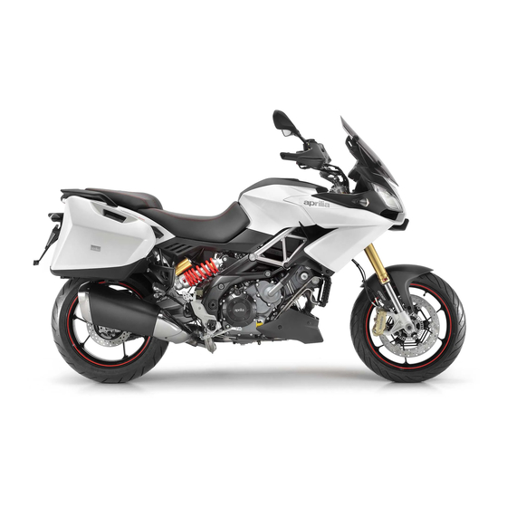
- Page 12 Max. height (fully extracted windshield) 1440 mm (56.69 in) Saddle height 870 mm (34.25 in) Wheelbase 1555 mm (61.22 in) Kerb weight (Caponord 1200) 251 kg (553.36 lb) Kerb weight (Caponord 1200 Travel Pack) 265 kg (584.22 lb) CHAR - 12...
- Page 13 CAPONORD 1200 Characteristics Specification Desc./Quantity Dry weight (without fuel) (Caponord 1200) 233 kg (513.68 lb) Dry weight (without fuel) (Caponord 1200 Travel Pack) 247 kg (544.54 lb) Engine NGINE Specification Desc./Quantity Model M558M Type 90° longitudinal V-twin, 4-stroke, 4 valves per cylinder, 2 over- head camshafts.
- Page 14 Steering inclination angle 24° Trail with suspension fully extended (without load) 128 mm (5.04 in) USPENSION Specification Desc./Quantity Front (Caponord 1200) Sachs telescopic "UPSIDE-DOWN" (upside-down stanchions) fork with full-adjustable stanchions with 43mm diameter (ad- CHAR - 14...
- Page 15 Sachs telescopic "UPSIDE-DOWN" (upside-down stanchions) fork with stanchions with 43mm diameter, hydraulic braking dynamic adjustment during extension and compression (semi- active Aprilia Dynamic Damping technology) on left stanchion; and of spring preload on right stanchion, manually adjustable Travel 170 mm (6.69 in)
- Page 16 CAPONORD 1200 Characteristics Specification Desc./Quantity Front tyre 120/70 ZR17" (58W) Front tyre pressure rider only: 2.4 bar (240 kPa) (34.81 PSI) rider + passenger: 2.5 bar (250 kPa) (36.26 PSI) Rear tyre 180/55 ZR17" (73W) Rear tyre pressure rider only: 2.6 bar (260 kPa) (37.71 PSI) rider + passenger: 2.8 bar (280 kPa) (40.61 PSI)
- Page 17 CAPONORD 1200 Characteristics RONT BRAKE PUMP pos. Description Type Quantity Torque Notes Brake pump fixing screws 10 ± 1,5 Nm (7.37 ± 1.10 lb CHAR - 17...
- Page 18 CAPONORD 1200 Characteristics ONTROLS HANDLEBAR pos. Description Type Quantity Torque Notes Upper U-bolt fixing screw M8x25 25 ± 3.75 Nm (18.44 ± 2.76 lb ft) Anti-vibration weight fastening screws 20 ± 3 Nm (14.75 ± 2.21 lb LUTCH CONTROL pos.
- Page 19 CAPONORD 1200 Characteristics NSTRUMENT SUPPORT Pos. Description Type Quantity Torque Notes Instrument panel to trellis fixing screws M8x25 25 ± 5 Nm (18.43 ± 3.68 lb OOLING SYSTEM pos. Description Type Quantity Torque Notes Electric fan fastener screw M4x45 3 Nm (2.21 lb ft)
- Page 20 CAPONORD 1200 Characteristics pos. Description Type Quantity Torque Notes Flanged TE screw fastening left Ra- M6x25 10 Nm (7.37 lb ft) diator to trellis Flanged TE screw fastening expan- M6x20 10 Nm (7.37 lb ft) sion tank OP FAIRING INDSHIELD Pos.
- Page 21 CAPONORD 1200 Characteristics UDGUARD Pos. Description Type Quantity Torque Notes Lug fixing screw M6x20 10 Nm (7.37 lb ft) Control unit support fixing screw M6x35 10 Nm (7.37 lb ft) Front with rear lug fixing screw 3.9x14 2 Nm (1.47 lb ft)
- Page 22 CAPONORD 1200 Characteristics RONT FAIRING Pos. Description Type Quantity Torque Notes Deflector fixing screw M5x12 6 Nm (4.42 lb ft) Deflector fixing screw M5x16 6 Nm (4.42 lb ft) Central part CHAR - 22...
- Page 23 CAPONORD 1200 Characteristics HROTTLE BODY pos. Description Type Quantity Torque Notes Intake union fastener screw 12 Nm (8.85 lb ft) Loctite 242 Map sensor fixing screw 5.5 Nm (4.05 lb ft) Injector fastener screw 12 Nm (8.85 lb ft) Loctite 242 Injection Throttle Body fastener 12 Nm (8.85 lb ft)
- Page 24 CAPONORD 1200 Characteristics IR FILTER BOX Pos. Description Type Quantity Torque Notes Cross head self-tapping screw fas- M5x20 3 Nm (2.21 lb ft) tening covers / filter box Cross head self-tapping screw fas- M5x20 3 Nm (2.21 lb ft) tening blow-by tank...
- Page 25 CAPONORD 1200 Characteristics ENTRE FRAME pos. Description Type Quantity Torque Notes Flanged nut fastening side panels to 80 Nm (59 lbf ft) engine RONT CHASSIS pos. Description Type Quantity Torque Notes TCEI screw fastening shock absorb- M10x30 50 Nm (36.88 lbf ft)
- Page 26 CAPONORD 1200 Characteristics UEL TANK Pos. Description Type Quantity Torque Notes Plastic ring nut 20 ± 3 Nm (14.75 ± 2.21 lb Level indicator fixing screws M6x16 3 ± 0.45 Nm (2.21 ± 0.33 lb Saddle fixing 3 ± 0.45 Nm (2.21 ± 0.33 lb...
- Page 27 CAPONORD 1200 Characteristics TAND pos. Description Type Quantity Torque Notes Fixing screw protection M6x16 5 ± 1 Nm (3.68 ± 0.74 lb ft) Plate fastening screws M8x30 25 ± 5 Nm (18.43 ± 3.68 lb Loctite 243 Stand screw 25 ± 5 Nm (18.43 ± 3.68 lb...
- Page 28 CAPONORD 1200 Characteristics EAR BRAKE PUMP pos. Description Type Quantity Torque Notes Rear brake lever pin 25 ± 3.75 Nm (18.44 ± 2.76 Loctite 243 lb ft) Microswitch fixing nuts 0.4 ± 0.08 Nm (0.29 ± 0.05 lb ft) Spring linking pin M5x7 6 ±...
- Page 29 CAPONORD 1200 Characteristics OOTRESTS pos. Description Type Quantity Torque Notes Rear brake pump fixing screws M6x20 10 ± 1.5 Nm (7.37 ± 1.11 lb Loctite 243 Footrest support fixing screws M8x40 30 ± 4.5 Nm (22.12 ± 3.31 Loctite 243...
- Page 30 CAPONORD 1200 Characteristics ANK COVER Pos. Description Type Quantity Torque Notes Covers fastening screws M5x9 3 ± 0.60 Nm (2.21 ± 0.44 lb ADDLE Pos. Description Type Quantity Torque Notes Saddle fixing screw M5x12 6 Nm (4.42 lb ft) CHAR - 30...
- Page 31 CAPONORD 1200 Characteristics ELMET COMPARTMENT Pos. Description Type Quantity Torque Notes Covers fastener screw M5x20 6 Nm (4.42 lb ft) Compartment fixing screw M5x12 6 Nm (4.42 lb ft) AIRINGS Pos. Description Type Quantity Torque Notes Fairing fastener screw M5x9 6 Nm (4.42 lb ft)
- Page 32 CAPONORD 1200 Characteristics Back side SYSTEM pos. Description Type Quantity Torque Notes ABS ECU fastener screw M6x25 10 Nm (7.37 lbf ft) Loctite 243 ABS ECU fastener nut 10 Nm (7.37 lbf ft) CHAR - 32...
- Page 33 CAPONORD 1200 Characteristics EAR SUSPENSION Pos. Description Type Quantity Torque Notes Upper TCEI mounting screw M10x50 50 Nm (36.88 lb ft) Lower TCEI mounting screw M10x80 50 Nm (36.88 lb ft) ADD Version EAR SUSPENSION A Pos. Description Type Quantity...
- Page 34 CAPONORD 1200 Characteristics EAR WHEEL pos. Description Type Quantity Torque Notes ● Fastening screws flexible coupling Rear wheel axle 120 ± 18 Nm (88.50 ± 13.27 lb ft) WINGARM pos. Description Type Quantity Torque Notes Swingarm Pin adjustment bushing 12 Nm (8.85 lb ft)
- Page 35 CAPONORD 1200 Characteristics pos. Description Type Quantity Torque Notes Swingarm pin ring nut 60 Nm (44.25 lb ft) Swingarm pin nut 90 Nm (66.38 lb ft) TPSI screw fastening rear stand M6x40 10 Nm (7.37 lb ft) bushing TBEI screw fastening chain guard to M5x9 6 Nm (4.42 lb ft)
- Page 36 CAPONORD 1200 Characteristics UGGAGE RACK Pos. Description Type Quantity Torque Notes Luggage rack screw 3.9x14 2 Nm (1.47 lb ft) Luggage rack cover screw M8x20 25 Nm (18.44 lb ft) Luggage rack fastener screw M8x25 25 Nm (18.44 lb ft)
- Page 37 CAPONORD 1200 Characteristics EAR BODYWORK Pos. Description Type Quantity Torque Notes Tail fairing fastener screw M5x12 6 Nm (4.42 lb ft) Panniers connection fixing screw License plate holder fastener screw 10 Nm (7.37 lb ft) EAR LIGHTS Pos. Description Type...
- Page 38 CAPONORD 1200 Characteristics Engine EAD COVER pos. Description Type Quantity Torque Notes Special screw for fastening head 9 Nm (6.64 lbf ft) cover Special screw for fastening head 9 Nm (6.64 lbf ft) cover Oil breather fastener screw 5.50 Nm (4.06 lbf ft) Spark plugs 10-12 Nm (7.38-8.85 lbf...
- Page 39 CAPONORD 1200 Characteristics pos. Description Type Quantity Torque Notes Water Temperature Sensor M12x1.5 22 Nm (16.22 lbf ft) Threaded plug for water sensor seat M12x1.5 10 Nm (7.38 lbf ft) Loctite Drise AL 506 Head stud bolt fastener nut - pre- M10x1.25...
- Page 40 CAPONORD 1200 Characteristics YLINDER pos. Description Type Quantity Torque Notes Chain tensioner fastener screw 13 Nm (9.59 lb ft) Cylinder plate fastener screw 7.84-9.81 Nm (5.78-7.23 lb ft) Chain tensioner adjustment screw 5.50 Nm (4.06 lb ft) CHAR - 40...
- Page 41 CAPONORD 1200 Characteristics TIMING SYSTEM pos. Description Type Quantity Torque Notes Camshaft gear fastener nut M15x1 90 Nm (66.38 lbf ft) Timing drive gear fastener screw M24x1.5 40 Nm (29.50 lbf ft) 3M SCOTCH GRIP 2353 Special screw for fastening mobile / 19 Nm (14.01 lbf ft)
- Page 42 CAPONORD 1200 Characteristics pos. Description Type Quantity Torque Notes Decompression device fixing screw torx M8 28.5 Nm (21.02 lbf ft) 3M SCOTCH GRIP 2353 Fastener screw 5.50 Nm (4.06 lbf ft) 3M SCOTCH GRIP 2353 RANKSHAFT pos. Description Type Quantity...
- Page 43 CAPONORD 1200 Characteristics IL PUMP pos. Description Type Quantity Torque Notes Oil drainage plug M16x1.5 19 Nm (14.01 lbf ft) Fastening oil sensor on clutch side 13 Nm (9.59 lbf ft) crankcase half Fastening oil filter union on clutch 20 Nm (14.75 lbf ft)
- Page 44 CAPONORD 1200 Characteristics EAR SELECTOR pos. Description Type Quantity Torque Notes Gear retainer pawl fastener screw 12 Nm (8.85 lb ft) Loctite dry loc 2040 Selector plate fastener screw 5.50 Nm (4.06 lb ft) 3M SCOTCH GRIP 2353 Screw fastening Desmodromic se- 20 Nm (14.75 lb ft)
- Page 45 CAPONORD 1200 Characteristics LUTCH COVER pos. Description Type Quantity Torque Notes Screw fastening Clutch Cover / inter- 13 Nm (9.59 lbf ft) mediate Clutch side cover Clutch fastener nut M24x1 170 Nm (125.38 lbf ft) Chamfer Fastening oil filler plug on Clutch cov- 2 Nm (1.48 lbf ft)
- Page 46 CAPONORD 1200 Characteristics LUTCH pos. Description Type Quantity Torque Notes Clutch spring fastener screw 11 Nm (8.11 lbf ft) ATER PUMP pos. Description Type Quantity Torque Notes Clutch side cover fastener screw 13 Nm (9.59 lbf ft) CHAR - 46...
- Page 47 CAPONORD 1200 Characteristics pos. Description Type Quantity Torque Notes Fastener screw for Pump Cover / 13 Nm (9.59 lbf ft) Clutch side cover Screw fastening Pump Cover / 13 Nm (9.59 lbf ft) Clutch Cover / clutch side crankcase half Nut fastening water pump drive gear 12 Nm (8.85 lbf ft)
- Page 48 CAPONORD 1200 Characteristics RANKCASE pos. Description Type Quantity Torque Notes Bearing retainer fastener screw 10 Nm (7.38 lbf ft) Loctite 270 Piston oil jet fastener screw 5.50 Nm (4.06 lbf ft) Loctite 270 Tapered plug for crankshaft main M8x1 15 Nm (11.06 lbf ft)
- Page 49 CAPONORD 1200 Characteristics RANKCASE pos. Description Type Quantity Torque Notes Special calibrated screw for gearbox M9x1 18 Nm (13.28 lbf ft) lubrication Screw fastening flywheel side / 13 Nm (9.59 lbf ft) clutch side crankcase halves Screw fastening flywheel side / 29 Nm (21.39 lbf ft)
- Page 50 CAPONORD 1200 Characteristics Crankcases are classified in two classes (1 or 2) depending on the diameter of the main bearing seat. The class is indicated on both crankcase halves, specifically, in the rear cylinder area on flywheel side crankcase halves and in the front cylinder area on clutch side crankcase halves.
- Page 51 CAPONORD 1200 Characteristics There are three crankshaft classes selectable for each bearing: • 4 - 5 - 6 for the flywheel side; • 7 - 8 - 9 for the clutch side; The class is stamped on the outer face of the crankshaft counterweight.
- Page 52 CAPONORD 1200 Characteristics RANKCASE CLASSES Specification Desc./Quantity Crankcase class A Centre-to-centre distance: 110.50 - 110.54 mm (4.3504 - 4.3519 in) Crankcase class B Centre-to-centre distance: 110.46 - 110.50 mm (4.3488 - 4.3504 in) See also Removing the flywheel cover Crankcase class (internal marking on second...
- Page 53 CAPONORD 1200 Characteristics Crankshaft class (crank pin) There are four different classes of crankshaft avail- able (0, 1, 2, 3), selected in relation to crank pin diameter. There are four different classes of crankshaft avail- able (E1, E2, ...) selectable in relation to connect- ing rod weight.
- Page 54 FUCHS TITAN SAF 1091 Fork oil (Caponord 1200) OJ RACING FORK OIL TYPE 01 Fork oil (Caponord 1200 Travel Pack) FUCHS TITAN SAF 1091 Actuator oil of the active rear single shock absorber (Caponord 1200 Travel Pack) AGIP MP GREASE...
- Page 55 INDEX OF TOPICS S-TOOLS PECIAL TOOLS...
- Page 56 CAPONORD 1200 Special tools PECIAL TOOLS Stores code Description 020709Y Engine support 020710Y Engine plate AP8140187 Engine support stand 020850Y Primary gear lock 020712Y Handle for Flywheel cover removal 020713Y Flywheel extractor S-TOOLS - 56...
- Page 57 CAPONORD 1200 Special tools Stores code Description 020714Y Dial gauge mounting 9100896 Clutch housing locking tool 020716Y Connecting rod locking 020894Y Pin snap ring fitting tool 020895Y Piston installation ring 020719Y Timing pin S-TOOLS - 57...
- Page 58 CAPONORD 1200 Special tools Stores code Description 020382Y Valve cotters removal tool 020896Y Bushing for valve removal 020720Y Timing tool 020376Y Adapter handle 020891Y Adapter 25 mm (0.98 in) 020362Y 12 mm guide S-TOOLS - 58...
- Page 59 CAPONORD 1200 Special tools Stores code Description 020724Y Gear control rod roller cage punch 020726Y Extractor for bushings 020727Y Punch for bushings 020884Y 46 mm wrench for steering ring nut 020193Y Gauge for oil pressure check AP8140612 Fuel pressure gauge...
- Page 60 CAPONORD 1200 Special tools Stores code Description AP8140199 Tool panel 8140426 Hooks for panel 020888Y Pliers for pre-fill pipe 020889Y Pumping member ring nut locking span- 020890Y Pumping member stanchion support rod 020922Y P.A.D.S. 020957Y Key for upper fork nut...
- Page 61 CAPONORD 1200 Special tools Stores code Description 020958Y Fork cartridge protection AP8140149 Protection for fitting operations AP8140189 Oil seal fitting tool for Ø 43 mm (1.69 in) orifices AP8140146 Weight S-TOOLS - 61...
- Page 62 INDEX OF TOPICS MAIN AINTENANCE...
- Page 63 Correct maintenance is fundamental for ensuring the longevity of your vehicle and maintaining optimum function and performance. To this end, Aprilia offers a set of checks and maintenance services (at the owner's expense), that are summarised in the table shown on the following page. Any minor faults must be reported without delay to an Authorised Aprilia Dealer or Sub-Dealer without waiting until the next scheduled service to solve it.
- Page 64 Fault warning light on instru- ment panel (4) Fuel lines (3) Clutch wear Brake pad wear Labour time - Caponord 1200 (minutes) Labour time - Caponord 1200 ADD (minutes) Spark plug At regular intervals, remove the spark plug and clean off any carbon deposits or replace as required.
- Page 65 CAPONORD 1200 Maintenance • Working on the left side of the vehicle, unscrew and remove the screw. • Turn the radiator forwards to act on the coils. • Unscrew and remove the two screws fixing coils to head cover. •...
- Page 66 CAPONORD 1200 Maintenance See also Fuel tank • Check the gap between the electrodes with a feeler gauge. CAUTION DO NOT ATTEMPT TO READJUST THE ELECTRODE GAP. The gap between the electrodes should be 0.6 - 0.7 mm (0.023 - 0.027 in) Wear limit is achieved when the gap for one of the two electrodes rea- ches 1.0 mm (0.039 in)
- Page 67 CAPONORD 1200 Maintenance Engine oil Check Check the engine oil level frequently. NOTE CARRY OUT MAINTENANCE OPERATIONS AT HALF THE INTERVALS SPECIFIED IF THE VE- HICLE IS USED IN PARTICULAR RAINY OR DUSTY CONDITIONS, OFF ROAD OR FOR TRACK USE.
- Page 68 CAPONORD 1200 Maintenance HOT OIL IS MORE FLUID AND WILL DRAIN OUT MORE EASILY AND COMPLETELY; IDEAL TEMPERATURE IS REACHED AFTER THE ENGINE HAS RUN FOR ABOUT TWENTY MINUTES. OIL BECOMES VERY HOT WHEN THE ENGINE IS HOT; BE CAREFUL NOT TO GET BURNED WHEN CARRYING OUT THE OPERATIONS DESCRIBED BELOW.
- Page 69 CAPONORD 1200 Maintenance • Unscrew and remove the cap to drain out the engine oil. • Unscrew and remove the engine oil fil- ter. • Fit a new engine oil filter. • Add engine oil up to the correct level.
- Page 70 CAPONORD 1200 Maintenance • Unscrew and remove the four screws. • Remove the air-box cover. • Remove the filtering element. Checking the valve clearance The following operation can be carried out also with the engine fitted on the vehicle. •...
- Page 71 CAPONORD 1200 Maintenance Removing the head cover • Remove the bowl tappets and the ad- justment shims using a magnet. NOTE GREASE THE BOWL TAPPETS AND THE ADJUSTMENT SHIMS PROPERLY EACH TIME THEY ARE REMOVED. • Replace calibrated pads with a pad thick enough to correct the valve clear- ance previously detected.
- Page 72 CAPONORD 1200 Maintenance • Apply THREEBOND on the head cover perimeter along the gasket housing. • Apply THREEBOND on the head in the areas indicated in the figure. MAIN - 72...
- Page 73 INDEX OF TOPICS TROUBL ROUBLESHOOTING...
- Page 74 CAPONORD 1200 Troubleshooting Engine TROUBL - 74...
- Page 75 INDEX OF TOPICS ELE SYS LECTRICAL SYSTEM...
- Page 76 CAPONORD 1200 Electrical system LECTRICAL SYSTEM pos. Description Type Quantity Torque Notes Coil fixing screw 5.50 Nm (4.06 lbf ft) TE screw fastening regulator to M6x30 10 Nm (7.37 lbf ft) frame Screw fastening ECU to filter box 3 Nm (2.21 lbf ft)
- Page 77 CAPONORD 1200 Electrical system • No.1 Main Cable Harness. • No.1 License Plate Cable Harness. • No. 25 Large plastic clamp (4.5x280). • No. 9 Small plastic clamp (2.5x160). • No. 4 Rubber clamp (long). • No. 5 Rubber clamp (short).
- Page 78 CAPONORD 1200 Electrical system 8. Fuel Pump Connector. 9. Key and aerial key connector (check correct passage). 10.RH and LH light switch connectors, front stop switch, clutch switch, MAP sensor front fork (with rubber plug well inserted), CDCi front fork.
- Page 79 CAPONORD 1200 Electrical system 40.Check the positioning of the horn and make sure that the mufflers are not stuck on the flap, check the presence of the clamp retaining the horn's cables. 41.Check the GAP between the tone wheel and the ABS sensors (it must be between 0.5 and 2mm).
- Page 80 CAPONORD 1200 Electrical system key: 1. MULTIPLE CONNECTORS ELE SYS - 80...
- Page 81 CAPONORD 1200 Electrical system 2. FRONT LEFT TURN INDICATOR 3. FRONT HEADLAMP 4. FRONT RIGHT TURN INDICATOR 5. HIGH BEAM LIGHTS RELAY 6. LIGHT RELAY 7. LEFT LIGHT SWITCH 8. HORN 9. BLUEDASH PRE-INSTALLATION 10. INSTRUMENT PANEL 11. HEATED HANDGRIPS (WHERE PROVIDED) 12.
- Page 82 72. FRONT MAP SENSOR 73. REAR MAP SENSOR 74. WATER TEMPERATURE SENSOR 75. SECONDARY FUSES 77. FRONT INJECTOR 2 (SYNERJET/EXTERNAL) 78. REAR INJECTOR 2 (SYNERJET/EXTERNAL) 80. BLUEDASH (IF FITTED) 81. FOG LIGHT LED (IF FITTED) CAPONORD 1200 TRAVEL PACK ELE SYS - 82...
- Page 83 CAPONORD 1200 Electrical system key: 1. MULTIPLE CONNECTORS ELE SYS - 83...
- Page 84 CAPONORD 1200 Electrical system 2. FRONT LEFT TURN INDICATOR 3. FRONT HEADLAMP 4. FRONT RIGHT TURN INDICATOR 5. HIGH BEAM LIGHTS RELAY 6. LIGHT RELAY 7. LEFT LIGHT SWITCH 8. HORN 9. BLUEDASH PRE-INSTALLATION 10. INSTRUMENT PANEL 11. HEATED HANDGRIPS (WHERE PROVIDED) 12.
- Page 85 CAPONORD 1200 Electrical system 40. MAIN FUSE 1 41. BATTERY 42. ELECTRIC FANS 43. ELECTRIC FANS RELAY 44. USB PORT 45. ECU DIAGNOSIS 46. AUXILIARY INJECTION RELAY 47. PRIMARY INJECTION RELAY 48. FUEL RESERVE SENSOR 1 (NTC) 49. FUEL RESERVE SENSOR 2 (LEVEL) 50.
- Page 86 CAPONORD 1200 Electrical system 78. REAR INJECTOR 2 (SYNERJET/EXTERNAL) 80. BLUEDASH (IF FITTED) 81. FOG LIGHT LED (IF FITTED) Colour key: Ar Orange Az Sky blue B Blue Bi White G Yellow Gr Grey M Brown N Black R Red...
- Page 87 CAPONORD 1200 Electrical system the connector (i.e., all terminals aligned at the same depth) and terminal integrity (i.e., that termi- nals are not loose, open/bent, etc.). For connec- tors whose terminals are not visible (e.g. Marelli control unit) use a metal cable of suitable diameter...
- Page 88 CAPONORD 1200 Electrical system Immobiliser System components Function detects the transponder code in the key and sends it to the instrument panel Level in electrical circuit diagram: Immobilizer Location: • on the vehicle: in the ignition switch as- sembly •...
- Page 89 CAPONORD 1200 Electrical system disconnected, check that there is not voltage at the circuit ends: if there is voltage, restore the cable harness. Error code B0006 (INSIDE ERROR) There is a fault in the instrument panel. Troubleshooting Replace the instrument panel.
- Page 90 CAPONORD 1200 Electrical system Check the mapping of the control unit and reset the vehicle configuration. OIL SENSOR Error code B0001 (OIL SENSOR FAILURE) Oil motor low pressure alarm: This alarm occurs when the engine is off and the pressure of the engine oil is low. If during the following OFF-ON key switching, the fault is not immediately detected, the error is no longer displayed.
- Page 91 CAPONORD 1200 Electrical system Check the cable harness of the CAN line. ENGINE TEMPERATURE Error code B0010 (ENGINE OVERTEMPERATURE) Error cause Engine temperature > 115 °C. Troubleshooting The error is no longer displayed when the temperature falls below 113 °C. If the error continues to be displayed also with low engine temperature, the failure is probably in the sensor that is shortcircuited or in the cable harness: perform the diagnosis by connecting to the engine control unit.
- Page 92 CAPONORD 1200 Electrical system stage "1" (pin 1-2), stage "2" (pin 1-3), stage "3" (pin 2-3). • Take the measurement; The correct value is determined by the value measured for each stage in which from time to time the resistance of the tester wires is subtracted, obtained by touching the two lugs.
- Page 93 CAPONORD 1200 Electrical system ESISTANCE MEASUREMENT Winding stage Ambient temperature (ohm) Afterwards heat stabilisation (ohm) Stage 1 0.15 - 0.20 0.18 - 0.23 Stage 2 0.15 - 0.20 0.18 - 0.23 Stage 3 0.15 - 0.20 0.18 - 0.23 Empty voltage •...
- Page 94 CAPONORD 1200 Electrical system OLD SHORT CIRCUIT CURRENT 2000 4000 6000 8000 RMS DC current (Arms) (average of the 3 stage 26 - 31 26 - 31 26 - 31 26 - 31 currents) Voltage on battery poles with engine speed always between 3000 - 5000 RPM •...
- Page 95 CAPONORD 1200 Electrical system • shorted to positive / open circuit, shorted to negative. Error cause • If shorted to positive: excessive voltage has been detected at PIN 58; if the circuit is open, shorted to negative: voltage equal to zero has been detected.
- Page 96 5 - Coils, petrol pump, injectors (15 A) 6 - Low beam/high beam light logic (15 A) 7 - Fans (15 A). 8 - VCU positive live (15 A) (only Caponord 1200 Travel Pack) Spare fuses (7.5 - 10 - 15 A)
- Page 97 CAPONORD 1200 Electrical system Control unit • Unscrew and remove the control unit cover screws. ELE SYS - 97...
- Page 98 CAPONORD 1200 Electrical system • Unscrew and remove the control unit fixing screw. • Slide off the control unit from the mountings and remove it from the ve- hicle. NOTE DURING THE REFITTING, PAY PARTICULAR ATTENTION TO FIX THE CONTROL UNIT IN THE MOUNTINGS.
- Page 99 CAPONORD 1200 Electrical system it controls the Ride by wire system, the injection/ignition, the system safety checks and the self-diagnosis function Level in electrical circuit diagram: Each level in which the main component involves the control unit Location: • on the vehicle: above the filter box •...
- Page 100 CAPONORD 1200 Electrical system DIAGNOSTICS INSTRUMENT: PARAMETERS • Engine revs (rpm) • Front throttle position (pot. 1) (°) ELE SYS - 100...
- Page 101 CAPONORD 1200 Electrical system • Rear throttle position (pot. 1) (°) • Front throttle position correction (°) • Rear throttle position correction (°) • Front lambda probe tension (mV) • Rear lambda probe tension (mV) • Correction front cylinder value (%) •...
- Page 102 CAPONORD 1200 Electrical system • Rear cylinder injection time (ms) • Nominal idle speed (rpm) • Vehicle speed (km/h) • Front wheel speed (km/h) • Rear wheel circumference (mm) • Final drive gear ratio CAUTION BEFORE CARRYING OUT ANY TROUBLESHOOTING, CAREFULLY READ THE GENERAL TROU- BLESHOOTING CONCEPTS FOR ELECTRICAL DEVICES AT THE BEGINNING OF THE CHECK AND CONTROL SECTION IN THE ELECTRICAL SYSTEM CHAPTER.
- Page 103 • Slightly twisted/Choked/Fully twisted Rpm sensor signals panel • Synchronized/Partially synchronized/Not synchronized Button + (during ATC setting) • Pressed/Released Button - (during ATC setting) • Pressed/Released ATC (Aprilia Traction Control) • Present/Not present Exhaust butterfly valve ELE SYS - 103...
- Page 104 CAPONORD 1200 Electrical system • Indeterminate / Search / Self-cleaning / Operation / Failure / Home position search Performing ATC (on bend) • Present/Not present AQS (Aprilia Quick Shift) • Present/Not present • Present/Not present Front brake lever • Pulled/Released rear brake pedal •...
- Page 105 CAPONORD 1200 Electrical system • Front cylinder side coil • Internal rear cylinder injector • Internal front cylinder injector • External front cylinder injector • External rear cylinder injector • Deleting stored errors • Freezes and saves the parameter and states values •...
- Page 106 CAPONORD 1200 Electrical system • short circuit to positive/ short circuit to negative / open circuit Error cause • If shorted to positive: excessive voltage has been detected at PIN 31. If shorted to negative: no voltage has been detected. If the circuit is open: an interruption has been detected Troubleshooting •...
- Page 107 CAPONORD 1200 Electrical system • Handle self-learning • Throttle self-learning with diagnostics instrument • EEPROM reset • Saved data file download • Saved data file deletion • Vehicle configuration • Exhaust valve (step 1) - Acquire home position • Exhaust valve (step 2) - Self-learning...
- Page 108 CAPONORD 1200 Electrical system DIAGNOSTICS INSTRUMENT:PARAMETERS • Battery voltage (V) • Tension potentiometer at the exhaust butterfly valve (mV) • Rotary sensor trace 1 (mV) • Rotary sensor trace 2 (mV) • Pressure sensor (mBar) • Temperature sensor (°C) •...
- Page 109 CAPONORD 1200 Electrical system • Travel limits not acquired / Manual / Automatic / Fault Exhaust butterfly valve automatic • Indeterminate / Seek / Verify / Adjustment / Fault / Zero Front Suspension Valve • Operation / Constant Current Fault / Zero Current Fault Rear suspension valve •...
- Page 110 CAPONORD 1200 Electrical system • The VCU memory was deleted following an unforeseen lack of supply; all stored data have been lost, such as the travel limits of the exhaust valve, of the shock absorber preload, or the idle position of the rotary potentiometer.
- Page 111 CAPONORD 1200 Electrical system • too high/too low Error cause • If too high: too high a voltage has been detected at PIN 42. If too low: too low a voltage has been detected at PIN 42. The instrument panel does not indicate the presence of this error even in the ATT status.
- Page 112 CAPONORD 1200 Electrical system • PIN 1- Ground connection (white) • PIN 2 - Power supply voltage/Output signal (white/brown) DIAGNOSIS INSTRUMENT Parameters: Speed (km/h) - Vehicle speed. ELECTRICAL ERRORS Speed sensor 5D90 electric malfunction: Electrical fault in sensor or cable harness.
- Page 113 CAPONORD 1200 Electrical system Troubleshooting: Check that the speed sensor and the tone wheel are installed. If they are not, install them. If they are, check the speed sensor retainer. If it is not OK, restore it. If it is, check if the tone wheel has the correct number of teeth or if it is dirty, deformed or wrongly fixed.
- Page 114 CAPONORD 1200 Electrical system restore them. If there is, PIN 2 of the sensor on the cable harness side, with the sensor disconnected and key set to ON, must have 12V voltage approximately: if there is no voltage, check PIN 2 for continuity with the vehicle ground connection: if it is grounded, restore the cable harness.
- Page 115 CAPONORD 1200 Electrical system OK, check that the tyre pressure is the correct one. If it is not OK, restore it; if it is OK, replace the speed sensor. Engine rpm sensor ENGINE SPEED SENSOR Function It informs crankshaft position and speed to the Marelli control unit.
- Page 116 CAPONORD 1200 Electrical system CARRY OUT THE TESTS FROM THE SENSOR CONNECTOR TO THE SENSOR. IF NOT OK, RE- STORE THE CABLE HARNESS/REPLACE THE SENSOR. IF OK, PERFORM THE TEST FROM PIN 20 AND 35 OF THE MARELLI CONTROL UNIT ENGINE CONNECTOR.
- Page 117 CAPONORD 1200 Electrical system The two throttle cables (opening and closing) actuate on a scroll mounted on a shaft which is sent back to its home position by a return spring. On the shaft covers there are 2 double track potentiometers (4 control tracks) by means of which the torque demand is read (and checked).
- Page 118 CAPONORD 1200 Electrical system • Example value with key ON: 3560 mV • Example value with engine on: - Voltage value of the rear potentiometer track C White rear connector throttle grip position sensor - track D • Example value with key ON: 3555 mV •...
- Page 119 CAPONORD 1200 Electrical system cated by the diagnostics instrument: if the voltage does not vary, there is a short circuit in the cable wiring; replace the throttle grip sensor if the voltage drops to zero. • if the circuit is open, shorted to negative: check the throttle grip sensor connector and the Marelli control unit connector.
- Page 120 CAPONORD 1200 Electrical system • If shorted to positive: excessive voltage has been detected at PIN 23 of the ENGINE con- nector. If the circuit is open, shorted to negative: voltage equal to zero has been detected at PIN 23 of the ENGINE connector Troubleshooting •...
- Page 121 CAPONORD 1200 Electrical system that is not functioning properly: if there is continuity, replace the control unit; if not, restore the wiring DIAGNOSTICS INSTRUMENT: LOGIC ERRORS Blue front connector throttle grip position (tracks A-B) P0154 • inconsistent signal Error cause •...
- Page 122 CAPONORD 1200 Electrical system RESET PROCEDURE • If Marelli control unit or its mapping are replaced or if you carry out control unit EEPROM zero setting or if you replace the throttle grip sensor, it is necessary to carry out the Handle...
- Page 123 CAPONORD 1200 Electrical system Front Cylinder Intake Pressure • Example value with key ON: 1004 mbar • Example value with engine on: 715 mbar • NOTE: pressure read by the front sensor Rear Cylinder Intake Pressure • Example value with key ON: 1003 mbar •...
- Page 124 CAPONORD 1200 Electrical system the key to OFF and check continuity between the ENGINE connector PIN 25 and the sensor connector PIN 1: if not OK, restore the cable harness; if OK, replace the control unit; if there is 5V voltage at PIN 1, and with key set to ON, check the continuity to ground of the sensor connector PIN 3: if not OK, restore the cable harness;...
- Page 125 CAPONORD 1200 Electrical system connector PIN 3 is a few tenths of an Ohm; If it is above that value, restore cable harness. Replace the sensor if it is correct. rear cylinder air pressure sensor P0108 • signal not valid.
- Page 126 CAPONORD 1200 Electrical system • A substantial difference between the estimated pressure and the measured pressure has been detected (for example, the hole for pressure reading is clogged or sensor screw is loose). Troubleshooting • Check the conditions of the intake manifold and cleanliness of the hole for reading the pres- sure: there is an evident defect in the intake and pressure reading systems.
- Page 127 CAPONORD 1200 Electrical system Engine temperature sensor Function It tells the engine temperature to the control unit to improve its performance and to calculate the en- gine friction for a better estimation of the generated torque. Operation / Operating principle NTC type sensor (resistance sensor, inversely variable with temperature).
- Page 128 CAPONORD 1200 Electrical system • Example value with engine on: 25° C • The temperature value is stored during engine start-up. With key ON, value -40°C is read. CAUTION BEFORE CARRYING OUT ANY TROUBLESHOOTING, CAREFULLY READ THE GENERAL TROU- BLESHOOTING CONCEPTS FOR ELECTRICAL DEVICES AT THE BEGINNING OF THE CHECK AND CONTROL SECTION IN THE ELECTRICAL SYSTEM CHAPTER.
- Page 129 CAPONORD 1200 Electrical system • Check the sensor connector and the ENGINE connector of the Marelli control unit. NOTES No error is detected if the sensor does not work correctly or the control unit connector or sensor terminals are rusty: then use the diagnostics instrument to check if the temperature indicated is the same as the engine temperature.
- Page 130 CAPONORD 1200 Electrical system Value drawn from the signal read without taking into account any recovery: the value in the exam- ple refers to an open circuit CAUTION BEFORE CARRYING OUT ANY TROUBLESHOOTING, CAREFULLY READ THE GENERAL TROUBLESHOOTING CONCEPTS FOR ELECTRICAL DEVICES AT THE BEGIN- NING OF THE CHECK AND CONTROL SECTION IN THE ELECTRICAL SYSTEM CHAPTER.
- Page 131 CAPONORD 1200 Electrical system in order to work properly, it should reach a high operating temperature: that is why there is a heating circuit inside. Level in electrical circuit diagram: Lambda probe FRONT CYLINDER LAMBDA PROBE Location: • on the vehicle: exhaust end behind the rear head •...
- Page 132 CAPONORD 1200 Electrical system Lambda sensor correction • Example value with key ON: 1.00 mV • Example value with engine on: 0.90 - 1.10mV In closed loop, the value must be close to 1.00 (values not within the 0.90 - 1.10 interval indicate a fault): for example, value 0.75 corresponds to +25% with respect to the reference injection time;...
- Page 133 CAPONORD 1200 Electrical system • shorted to positive: with key set to ON, disconnect the sensor connector and measure PIN 1 voltage on the cable harness side (grey cable): if there is voltage (5 or 12 V), restore the cable harness; if there is not, replace the lambda probe.
- Page 134 CAPONORD 1200 Electrical system • short circuit to positive/ open circuit, short circuit to negative Error cause • If shorted to positive: excessive voltage has been detected at PIN 44 of the ENGINE con- nector. If the circuit is open, shorted to negative: voltage equal to zero has been detected at PIN 44 of the ENGINE connector.
- Page 135 CAPONORD 1200 Electrical system Function To supply the correct amount of petrol at the right timing. Operation / Operating principle Injector coil is excited for the petrol passage to open. The external injectors (Synerject) are always working, whereas the internal ones (Marelli, aka "high- pressure"...
- Page 136 CAPONORD 1200 Electrical system Electrical specifications: • internal injectors (Marelli): 14.8 Ω ± 5% (at ambient temp.) • external injectors (Synerject): 12.0 Ω ± 5% (at ambient temp.) Pin out: 1. Fuel system 2. Negative from control unit DIAGNOSTICS INSTRUMENT:PARAMETERS Front cylinder injection time •...
- Page 137 CAPONORD 1200 Electrical system relay and injector activation. The continuity of the wiring is necessary for correct activation: no error indications are displayed in case of lack of activation. Internal rear cylinder injector • The auxiliary injection relay (No. 46 in the wiring diagram, placed in the front relay box, left side;...
- Page 138 CAPONORD 1200 Electrical system • If shorted to negative: disconnect the injector connector, set the key to ON and check if there is a ground connection on the white/green cable: if there is connection, restore the cable harness. If there is no connection, replace the injector.
- Page 139 CAPONORD 1200 Electrical system • If the circuit is open: check the connector on the component and the Marelli control unit connector: if not OK, restore. If OK, check cable continuity between the ENGINE PIN 53 and component PIN 2 and restore the cable harness.
- Page 140 CAPONORD 1200 Electrical system Electrical characteristics: PIN 1-2: 0.5 - 1 ohm; PIN 3-4: you do not need to measure the component electrical resistance since it works correctly with suitable supply from the instrument panel only. Check correct operation as follows: connect in series a bulb of approxi- mately 2 W: it should turn on if the tank is in reserve, otherwise, it remains off.
- Page 141 CAPONORD 1200 Electrical system Marelli control unit: if not OK, restore; if OK, check continuity of cable harness (Brown/Black cable) Coil Coils key: 1. Front cylinder central coil 2. Front cylinder side coil 3. Rear cylinder central coil 4. Rear cylinder side coil...
- Page 142 CAPONORD 1200 Electrical system 0.7 - 0.9 Ω at ambient temperature Pin out: 1. Power supply + Vbatt 2. Secondary circuit to ground 3. Activation from control unit DIAGNOSTICS INSTRUMENT:PARAMETERS Example value with key ON: Current ignition advance. Example value with engine on: Indicates the cylinder advance where combustion will take place.
- Page 143 CAPONORD 1200 Electrical system • shorted to positive / shorted to negative, open circuit. Error cause • If shorted to positive: excessive voltage has been detected at PIN 28 of the ENGINE con- nector. If the circuit is open, shorted to negative: voltage equal to zero has been detected at PIN 28 of the ENGINE connector.
- Page 144 CAPONORD 1200 Electrical system • If shorted to positive: excessive voltage has been detected at PIN 2 of the ENGINE con- nector. If the circuit is open, shorted to negative: voltage equal to zero has been detected at PIN 2 of the ENGINE connector.
- Page 145 CAPONORD 1200 Electrical system Throttle body Function Sends to the injection control unit the throttle po- sition and activates the throttle according to the control unit Operation / Operating principle All the unit internal components (potentiometer and electric motor) are contactless; therefore, no electrical diagnosis is possible for the throttle body, but for the circuits connected to it only.
- Page 146 CAPONORD 1200 Electrical system • Example value with key ON: 5.5° • Example value with engine at idle: 2.1° With key set to ON, the throttle is kept in position by the springs (around 5 -7°). After the engine starts up at idle, the throttle is kept close to the mechanical minimum (above or equal to 0.5°).
- Page 147 CAPONORD 1200 Electrical system Rear throttle Potentiometer 2 (voltage) • Example value with key ON: 4226 mV • Example value with engine on: 4372 mV Key to throttle connectors figure: • A - Front cylinder throttle connector • B - Rear cylinder throttle connector Front cylinder throttle Limp Home position •...
- Page 148 CAPONORD 1200 Electrical system Indicates whether the self-acquisition process through the diagnosis instrument has/has not been car- ried out: if it has been carried out once, will always be carried out unless EEPROM control unit zero setting is carried out...
- Page 149 CAPONORD 1200 Electrical system there is power (+5 V) at the throttle body connector PIN 2, and that PIN 6 is connected to ground. If both are correct, replace the throttle body potentiometer 1 sensor, rear throttle position P0125 •...
- Page 150 CAPONORD 1200 Electrical system • short circuit to positive / short circuit to negative / open circuit, overvoltage, excessive internal temperature. Error cause • If shorted to positive: excessive voltage has been detected at PIN 29 - 41. If shorted to negative: no voltage has been detected.
- Page 151 CAPONORD 1200 Electrical system throttle body connector and control unit connector and check if there is cables continuity; if there is no continuity, restore the cable harness. If there is continuity, with the throttle body connector connected, check that the resistance, from the throttle control unit connector, between PIN 3 and 15 is within 1 and 2.5 Ohm;...
- Page 152 CAPONORD 1200 Electrical system • Potentiometer 1 and potentiometer 2 do not show a logical value: the sum of the two voltages should be constant. The cause may be a malfunction in one of the two sensors or an ab-...
- Page 153 CAPONORD 1200 Electrical system • Potentiometer 1 and potentiometer 2 do not show a logical value: the sum of the two voltages should be constant. The cause may be a malfunction in one of the two sensors or an ab-...
- Page 154 CAPONORD 1200 Electrical system • A correct throttle rotation cannot be detected given low ambient and engine temperatures: some ice may have formed in the duct (at each key ON). The instrument panel does not indicate the presence of this error even in the ATT status Troubleshooting •...
- Page 155 CAPONORD 1200 Electrical system • Check if the throttle body and the intake duct are clean. If OK, replace the throttle body Rear throttle minimum mechanical position self-acquisition P0182 • failed test Error cause • Position of the throttle stop not within the expected field (at each key ON) Troubleshooting •...
- Page 156 CAPONORD 1200 Electrical system ENGINE IS STARTED, THE ACTIVATION IS NOT COMPLETED AND THE STOP LIGHTS DO NOT TURN ON. EVERY 150 KEY-ONs, HOWEVER, THE THROTTLE VALVES ARE FORCED TO ACTI- VATION. IF START-UP IS ATTEMPTED DURING THIS ACTIVATION (WHICH REQUIRES 3 SEC- ONDS), THE ENGINE WILL NOT START.
- Page 157 CAPONORD 1200 Electrical system Neutral sensor Function It tells the gear position to the control unit, from the 1st gear to the 6th gear, and if the gear is neutral or riding. Operation / Operating principle The sensor has 2 circuits: one to indicate the en-...
- Page 158 CAPONORD 1200 Electrical system DIAGNOSTICS INSTRUMENT: ELECTRICAL ERRORS Gear sensor P0461 • shorted to positive or open circuit / shorted to negative. Error cause • If the circuit is open, shorted to positive: excessive voltage has been detected at PIN 72. If shorted to negative: voltage equal to zero has been detected at PIN 72.
- Page 159 CAPONORD 1200 Electrical system 1. Ground connection 2. Voltage 12V Electrical specifications: • Side Stand Up: closed circuit (continu- ity) • Side Stand Down: open circuit (infinite resistance) CAUTION BEFORE CARRYING OUT ANY TROUBLESHOOTING, CAREFULLY READ THE GENERAL TROUBLESHOOTING CONCEPTS FOR ELECTRICAL DEVICES AT THE BEGIN- NING OF THE CHECK AND CONTROL SECTION IN THE ELECTRICAL SYSTEM CHAPTER.
- Page 160 CAPONORD 1200 Electrical system Electrical specifications: • Sensor in vertical position: open circuit (resistance: 62 kOhm) • Sensor inverted: closed circuit (con- tinuity) Pin out: 1. Voltage 5V 2. Ground connection 3. Signal CAUTION BEFORE CARRYING OUT ANY TROUBLESHOOTING, CAREFULLY READ THE GENERAL TROUBLESHOOTING...
- Page 161 CAPONORD 1200 Electrical system Electric fan circuit Function Radiator fan and coolant - Operation Operation / Operating principle When the control unit detects a temperature of ap- prox. 102 °C, it closes the fan control relay pickup circuit to ground...
- Page 162 CAPONORD 1200 Electrical system • short circuit to positive/ short circuit to negative / open circuit Error cause • If shorted to positive: excessive voltage has been detected at PIN 61 of the VEHICLE con- nector. If shorted to negative: no voltage has been detected. If the circuit is open: 5V voltage has been detected.
- Page 163 CAPONORD 1200 Electrical system Pin out: 1 blue/green cable: ground connection 2 yellow/red cable: 5 V CAUTION BEFORE CARRYING OUT ANY TROUBLESHOOTING, CAREFULLY READ THE GENERAL TROUBLESHOOTING CONCEPTS FOR ELECTRICAL DEVICES AT THE BEGIN- NING OF THE CHECK AND CONTROL SECTION IN THE ELECTRICAL SYSTEM CHAPTER.
- Page 164 With bike stopped and in neutral the valve stays closed, regardless of rpm. Level in electrical circuit diagram: Exhaust valve control unit - Caponord 1200 VCU (Vehicle Control Unit) control unit - Caponord 1200 Travel Pack Location: •...
- Page 165 CAPONORD 1200 Electrical system DIAGNOSTICS INSTRUMENT: ADJUSTMENTS Exhaust valve - Zero position search • After having pressed the enter button for the zero position search, shut off the vehicle and leave the keys in OFF, even in the event that the instruments indicate the opposite.
- Page 166 CAPONORD 1200 Electrical system • excessive time / search not performed, wrong stroke Error cause • If time is excessive: failed memorisation of the travel limit positions of the valve. The EVC control unit is not able to record the valve's travel limits: possible interruption of the circuit.
- Page 167 PIN 2 of the component: if the insulation is not present, restore the cabling, otherwise replace the component. CAPONORD 1200 TRAVEL PACK VCU ERRORS Error control output exhaust valve Status Flag active C1613 Error cause •...
- Page 168 CAPONORD 1200 Electrical system between PIN 5 valve - PIN L2 VCU. If the cable harness is not damaged, replace the com- ponent. Error potentiometer exhaust valve shortcircuit C1707 Error cause • An excessive or null tension has been detected on PIN B4 VCU.
- Page 169 CAPONORD 1200 Electrical system - 3rd gear: 50 - 100 km/h; - 4th gear: 60 - 120 km/h; - 5th gear: 65 - 160 km/h; - 6th gear: 70 - 180 km/h. Once the desired speed is reached, the system...
- Page 170 CAPONORD 1200 Electrical system • Connector: under the dashboard cov- Pin out: M/N - Ground Gr - Signal (WHERE DIAGNOSIS IS AVAILABLE) DIAGNOSTICS INSTRUMENT: ELECTRICAL ERRORS VCU ERRORS Error Cruise Control ON/OFF button shortcircuit C1401 Error cause • A shortcircuit on PIN A4 or on PIN F4 of the VCU connector has been detected.
- Page 171 CAPONORD 1200 Electrical system Brake switch (WHERE DIAGNOSIS IS AVAILABLE) Function Communicate the braking phase to the VCU con- trol unit. Operation / Operating principle On the basis of the condition of the brake lever (pulled/released) the switch communicates the status to the VCU control unit.
- Page 172 Operation / Operating principle The system, by means of the VCU control unit (Vehicle Control Unit), measures in real time the energy transmitted to Caponord 1200 (damping of the shock absorber) from the roughness of the ELE SYS - 172...
- Page 173 CAPONORD 1200 Electrical system road surface and it adapts the calibration of the suspension in real time in order to maximise com- fort and keep the correct setup of the motorbike. Level in electrical circuit diagram: VCU (Vehicle Control Unit) control unit Location: •...
- Page 174 The system, by means of the VCU control unit (Vehicle Control Unit), measures in real time the energy transmitted to Caponord 1200 (damping of the shock absorber) from the roughness of the road surface and it adapts the calibration of the suspension in real time in order to maximise com- fort and keep the correct setup of the motorbike.
- Page 175 CAPONORD 1200 Electrical system Pin out: 1. Supply from VCU 2. Output 1 3. - 4. Supply from VCU 5. Output 2 6. - 7. Ground from VCU 8. Ground from VCU DIAGNOSTICS INSTRUMENT: ADJUSTMENTS Rotary sensor reset • When the motorbike comes off the assembly line, a setup measurement (in mm) is set (height from the ground) that the system recognises as reference position.
- Page 176 CAPONORD 1200 Electrical system • If shortcircuit: disconnect the connector of the rotary sensor and check its insulation from ground and supply system of PIN 5: if the insulation is not present, restore the cabling, otherwise replace the sensor. •...
- Page 177 CAPONORD 1200 Electrical system not met (speed and constant setup), it acts on the preload until it reaches the ideal setup. If the system has already reached the ideal posi- tion, it will make no further adjustments. Level in electrical circuit diagram:...
- Page 178 CAPONORD 1200 Electrical system • Check the preload motor because it is likely to be mechanically locked, otherwise replace the motor. Error preload motor control open circuit C1621 Error cause • An interruption of the circuit has been detected. Troubleshooting •...
- Page 179 PIN 2 motor - PIN M1 VCU. If all the above-mentioned tests have a positive out- come, replace the motor. Connectors EVC (EXHAUST VALVE CONTROL UNIT) (CAPONORD 1200) EVC pin out key: A1. Exhaust valve engine "B" A2. CAN L line A3.
- Page 180 C5. Power ground connection 1 C6. Power ground connection 2 C7. Power ground connection 3 C8. - VCU (VEHICLE CONTROL UNIT) (CAPONORD 1200 TRAVEL PACK) VCU pin out key: A1. Battery supply A2. Pump engine encoder 1 A3. Front pressure sensor A4.
- Page 181 CAPONORD 1200 Electrical system B1:. Front solenoid valve positive B2:. Pump engine encoder 2 B3:. Rotary sensor signal 1 B4:. Exhaust valve potentiometer signal C1. Front solenoid valve negative C2. Front stop switch C3. Rotary sensor signal 2 C4. - D1.
- Page 182 CAPONORD 1200 Electrical system Engine pinout key: Rear cylinder side spark plug coil control output PIN 1 Front cylinder side spark plug coil control output PIN 2 Rear throttle motor output (+) PIN 3 Analogue ground connection 2 PIN 4...
- Page 183 CAPONORD 1200 Electrical system Track C hand grip input PIN 23 Front cylinder intake pressure sensor input PIN 24 Reference voltage output + 5 V: tracks A-C, front throttle and pressure sensor PIN 25/51 Reference voltage output + 5V: tracks B-D and rear throttle PIN 26...
- Page 184 CAPONORD 1200 Electrical system Vehicle pinout key: Front cylinder 1 injector control output PIN 53 Clutch sensor input PIN 56 Analogue ground connection 2 PIN 57 "Start engine" switch input PIN 58 Electric fan relay control output PIN 61 Reference voltage output + 5V: tracks B-D and rear throttle PIN 63...
- Page 185 CAPONORD 1200 Electrical system Dashboard Grey-bodied instrument panel pinout key: 1. Live supply ELE SYS - 185...
- Page 186 CAPONORD 1200 Electrical system 2. RH indicator switch 3. - 4. High beam warning light 5. - 6. Signal SELECT 3 (ENTER) 7. Signal SELECT 2 (DOWN) 8. Signal SELECT 1 (UP) 9. Fuel reserve warning light 10. Fuel level signal 11.
- Page 187 CAPONORD 1200 Electrical system 22. Power from battery 3 23. - 24. Signal aerial "B" 25. Signal aerial "A" 26. CAN H line 27. CAN L line 28. ABS warning light 29. Sensors analogue ground connection 1 30. Sensors analogue ground connection 2 31.
- Page 188 CAPONORD 1200 Electrical system ABS control unit pin out key: 1. Power ground connection 1 2. Power ground connection 2 3. Vehicle speed signal 4. Live supply 5. CAN H line 6. CAN L line 7. - 8. ABS warning light 9.
- Page 189 CAPONORD 1200 Electrical system • Communication speed: messages travel at a speed of 250 kbps (data arrive at nodes every 20 ms, i.e. 50 times/second). CAN PROTOCOL (CONT. NETWORK AREA) The communication protocol is CSMA/CD (Carrier Sense Multiple Access w/ Collision Detection).
- Page 190 CAPONORD 1200 Electrical system • Replace the Marelli control unit. CAN line without signals U1602 • Bus Off. Error cause • No communication on CAN line (PIN 66 and/or PIN 80): problem on the whole network (for example, battery cut-off or short circuited or shorted to ground).
- Page 191 Example: if the bike has an ABS system the correct state that should be found in the diagnostics instrument device status screen will be: Aprilia Traction Control present. In the event of a bike with ABS system present and indication of the diagnostics instrument of: Aprilia Traction Control not present, update the control unit.
- Page 192 CAPONORD 1200 Electrical system Error cause • The VCU does not receive the signal from the ABS control unit. Troubleshooting • Check the continuity of the cable between PIN K2 VCU - PIN 6 ABS control unit and between PIN J2 VCU - PIN 5 ABS control unit. The error is automatically memorised when the com- munication between the two control units is restored.
- Page 193 CAPONORD 1200 Electrical system VCU - PIN 26 instrument panel (black connector). Check also the insulation of the two cables between themselves, from supply and ground. ELE SYS - 193...
- Page 194 INDEX OF TOPICS ENG VE NGINE FROM VEHICLE...
- Page 195 CAPONORD 1200 Engine from vehicle RONT CHASSIS pos. Description Type Quantity Torque Notes TCEI screw fastening shock absorb- M10x30 50 Nm (36.88 lbf ft) er counterplate to RH frame bracket Flanged nut fastening Trellis to frame 80 Nm (59 lbf ft)
- Page 196 CAPONORD 1200 Engine from vehicle ENTRE FRAME pos. Description Type Quantity Torque Notes Flanged nut fastening side panels to 80 Nm (59 lbf ft) engine ENGINE pos. Description Type Quantity Torque Notes Flanged TE screw fastening pinion M10x1.25 50 Nm (36.88 lbf ft)
- Page 197 CAPONORD 1200 Engine from vehicle pos. Description Type Quantity Torque Notes TCEI screw fastening Pin to gearbox M6x16 12 Nm (8.85 lbf ft) lever and Gearbox Lever to knurled shaft LH lock nut for ball joint 10 Nm (7.37 lbf ft) RH lock nut for ball joint 10 Nm (7.37 lbf ft)
- Page 198 CAPONORD 1200 Engine from vehicle • Slide out bushing and O-ring from gearbox secondary shaft. • Disengage the spring. • Unscrew and remove the three nuts from the front exhaust manifold ENG VE - 198...
- Page 199 CAPONORD 1200 Engine from vehicle • Disengage the spring joining the cen- tral exhaust manifold to the rear ex- haust manifold. • Remove the front exhaust manifold, moving the central exhaust manifold. • Unscrew and remove the catalytic con- verter mounting screw •...
- Page 200 CAPONORD 1200 Engine from vehicle • Unscrew and remove the three screws. • Remove the clutch control cylinder. • Lock the plunger using a clamp. • Undo and remove the two screws and remove the pinion protection case. • Unscrew and remove the two clutch support screws.
- Page 201 CAPONORD 1200 Engine from vehicle • Disconnect the side stand sensor con- nector. • Disconnect the gear in neutral sensor connector. • Slacken the gearing chain tension. • Unscrew and remove the screw; col- lect the washer and the spacer.
- Page 202 CAPONORD 1200 Engine from vehicle • Loosen the screw and slide off the gear transmission connecting rod keeping it linked to the gear shift lever through the rod. Removing the engine from the vehicle • Carry out the operations described un- der Vehicle preparation.
- Page 203 CAPONORD 1200 Engine from vehicle • Unscrew and remove the rear coil fix- ing screws. • Slide out the rear coils. • Slide off the rear top pin and collect the washer. • Remove the two spacers. The thinner spacer is on the right.
- Page 204 CAPONORD 1200 Engine from vehicle • Slide off the rear bottom pin and collect the washer. • Remove the bottom spacer on the right side. • Slide off the front pin and collect the washer. • Remove the bottom spacer on the right side.
- Page 205 CAPONORD 1200 Engine from vehicle • Unscrew and remove the screw. • Release the ground points. • Unscrew and remove the two screws of the ECU. • Move the ECU aside but keep it connected to the wiring harness. •...
- Page 206 CAPONORD 1200 Engine from vehicle • Lift the throttle body but keep it con- nected to the wiring harness. • Disconnect the engine temperature sensor from the front cylinder. • Disconnect the alternator connectors. ENG VE - 206...
- Page 207 CAPONORD 1200 Engine from vehicle • Disconnect the throttle body and fasten it using an elastic band. • Unscrew and remove the screws, slid- ing out the front coils. • Lower the engine and take it out of the chassis.
- Page 208 CAPONORD 1200 Engine from vehicle • Working on the right side, insert the three bolts with their washers. • Working on the right side, place the spacers on the three bolts between the engine block and the chassis. CAUTION THE SPACERS HAVE DIFFERENT SIZES. REFIT THEM IN THE SAME WAY THEY WERE BEFORE BEING REMOVED.
- Page 209 CAPONORD 1200 Engine from vehicle See also Vehicle preparation Adjusting ENG VE - 209...
- Page 210 INDEX OF TOPICS NGINE...
- Page 211 CAPONORD 1200 Engine • Use the special plate to duly support the engine during the servicing opera- tions. CAUTION TAKE PARTICULAR CARE TO ENSURE THAT THE EN- GINE AND ENGINE MOUNTING ARE STABLE AND EN- SURE THAT THE ENGINE IS SECURELY FASTENED TO THE MOUNTING PLATE.
- Page 212 CAPONORD 1200 Engine 8. Complete transmission gear shaft 9. Forks 10.Fork shaft 11.Gear selector 12.Fork shaft 13.Fork 14.Gear selector drum 15.M8x1.25 threaded pin 16.Selector locking plate 17.Complete main gear shaft 18.TE flanged screw, M6x15 19.Complete index lever 20.Spring 21.Nut 22.Threaded pin...
- Page 213 CAPONORD 1200 Engine 2. 2nd gear on primary Z=17 3. 3rd - 4th gear on secondary Z=20/22 4. 5th gear on primary Z=23 5. 6th gear on primary Z=24 6. Thrust washer 7. Circlip 8. Thrust washer 9. Thrust washer 10.Circlip...
- Page 214 CAPONORD 1200 Engine See also Splitting the crankcase halves • Slide off the desmodromic drum con- trol. • Remove the three gear selection forks. CAUTION THE MAIN SHAFT FORK IS SMALLER THAN THOSE OF THE SECONDARY SHAFT. ALL THE SECONDARY SHAFT FORKS ARE THE SAME SIZE.
- Page 215 CAPONORD 1200 Engine • Carefully rotate the engine support. • Carefully slide off the whole gear unit. • Repeat the removal operations but in reverse order. ENG - 215...
- Page 216 CAPONORD 1200 Engine Gear selector EAR SELECTOR pos. Description Type Quantity Torque Notes Gear retainer pawl fastener screw 12 Nm (8.85 lb ft) Loctite dry loc 2040 Selector plate fastener screw 5.50 Nm (4.06 lb ft) 3M SCOTCH GRIP 2353 Screw fastening Desmodromic se- 20 Nm (14.75 lb ft)
- Page 217 CAPONORD 1200 Engine Disassembling the clutch Collect the washer. NOTE REPLACE THE WASHER ON EVERY SERVICING • Heat the screws of the gearbox selec- tor mounting plate. • Unscrew and remove the three screws fastening the gearbox selector mount- ing plate.
- Page 218 CAPONORD 1200 Engine Checking the gear selector Selector spring In the position shown, ensure that the gap between spring ends is +/- 0.4 mm (0.016 in), compared to the same gap measured at the corresponding teeth. Pawl Make sure that both pawl tips run free, without...
- Page 219 CAPONORD 1200 Engine Gearbox Selector Shaft Removal • Place the left hand crankcase in a press and extract the roller cage with the specific tool. NOTE REPEAT THE SAME OPERATION FOR THE RIGHT HAND CRANKCASE HALF. Specific tooling 020724Y Gear control rod roller cage punch INSTALLATION •...
- Page 220 CAPONORD 1200 Engine Removing the starter motor • Disconnect the starter motor power supply cable. • Unscrew and remove the two screws and remove the starter motor. ENG - 220...
- Page 221 CAPONORD 1200 Engine Generator side GNITION pos. Description Type Quantity Torque Notes Spark plug 11 Nm (8.11 lb ft) Freewheel Ring fastener screw 14 Nm (10.33 lb ft) 3M SCOTCH GRIP 2353 Screw fixing rotor - Crankshaft - (12 M12x1.25 130 Nm (95.88 lb ft)
- Page 222 CAPONORD 1200 Engine Removing the flywheel cover • Remove the flywheel cover inspection cap. • Unscrew and remove the ten screws. • Remove the flywheel cover using the specific tool. Specific tooling 020712Y Handle for Flywheel cover removal • Collect the gasket and the two dowel pins.
- Page 223 CAPONORD 1200 Engine Removing the flywheel cover components • Remove the two pick-up fixing screws. • Remove the three stator fixing screws. CAUTION THE PICK-UP AND STATOR SHALL BE REMOVED SIMUL- TANEOUSLY AS THEY ARE PART OF THE SAME ELEC- TRICAL BRANCH.
- Page 224 CAPONORD 1200 Engine • Screw the anticlockwise bolt of the special tool on the external body. • Keeping the external body blocked and gripping the key, screw the anticlock- wise bolt so as to remove the flywheel from the crankshaft.
- Page 225 CAPONORD 1200 Engine • Collect the crankshaft woodruff key. Freewheel removal • Remove the flywheel. • Remove the freewheel gear. • Heat the magneto flywheel with the specific heater. • Unscrew and remove the six screws. • Remove the bearing retainer and bear- ing from the magneto flywheel.
- Page 226 CAPONORD 1200 Engine Installing the flywheel • Insert the woodruff key on the crank- shaft. • Insert the start-up transmission gear after applying a layer of grease. • Insert the flywheel on the crankshaft. • Screw the screw together with the washer but without tightening.
- Page 227 CAPONORD 1200 Engine Specific tooling 020713Y Flywheel extractor • Place the retention plate. • Tighten the screw. Clutch side ATER PUMP pos. Description Type Quantity Torque Notes Clutch side cover fastener screw 13 Nm (9.59 lbf ft) Fastener screw for Pump Cover / 13 Nm (9.59 lbf ft)
- Page 228 CAPONORD 1200 Engine pos. Description Type Quantity Torque Notes Water pump support plug M6x10 6.5 Nm (4.79 lbf ft) 3M SCOTCH GRIP 2353 • Unscrew and remove the thirteen screws in a cross pattern (the two screws also retaining the water pump cover are longer than the other eleven ones).
- Page 229 CAPONORD 1200 Engine Removing the clutch cover LUTCH COVER pos. Description Type Quantity Torque Notes Screw fastening Clutch Cover / inter- 13 Nm (9.59 lbf ft) mediate Clutch side cover Clutch fastener nut M24x1 170 Nm (125.38 lbf ft) Chamfer Fastening oil filler plug on Clutch cov- 2 Nm (1.48 lbf ft)
- Page 230 CAPONORD 1200 Engine Removing the clutch cover alone is only recom- mended when replacing the clutch plates. When removing the entire clutch assembly, removing the clutch side cover is recommended. However, removing the entire clutch assembly is possible by removing the clutch cover alone. In this case, proceed as follows: •...
- Page 231 CAPONORD 1200 Engine • Remove the clutch-side cover. • Unscrew and remove the six screws by loosening them 1/4 of a turn at a time; operate in stages and diagonally, and retrieve the washers and the clutch springs. • Remove the thrust plate, the plates and belleville washer.
- Page 232 CAPONORD 1200 Engine • Remove the clutch control rod. • Fasten the clutch housing using the specific tool. Specific tooling 9100896 Clutch housing locking tool • Unscrew and remove the clutch hub nut. • Remove the washer to be chamfered.
- Page 233 CAPONORD 1200 Engine • Remove the clutch hub. • Collect the washer between the clutch hub and the housing. • Collect the clutch housing. • Collect the spacer and the needle bearings. ENG - 233...
- Page 234 CAPONORD 1200 Engine • Collect the special shim featuring two thicknesses. Checking the clutch plates • Lay the friction discs and steel discs on a level surface and check them for cracks and potential distortions. Maximum distortion allowed: 0.20 mm (0.0079 •...
- Page 235 CAPONORD 1200 Engine Checking the clutch housing • Remove the clutch bell. • Remove the seeger ring. • Remove the oil pump control gear. UPON REFITTING, THE GEAR COLLAR MUST ALWAYS BE FACING THE CLUTCH BELL. • Remove the rotation locking pin from the oil pump control gear.
- Page 236 CAPONORD 1200 Engine Checking the pusher plate Check the thrust plate and the bearing for damage and wear. If necessary, replace the parts. Checking the clutch hub Check the clutch hub for damage and wear that may result in clutch irregular operation. If neces- sary, replace the bell.
- Page 237 CAPONORD 1200 Engine Assembling the clutch • Fit the shim washer. • Fit the needle bearing and the spacer. • Fit the clutch housing. • Make sure that the oil pump control drive gear of the clutch housing engag- es correctly with the oil pump driven gear.
- Page 238 CAPONORD 1200 Engine • Position the clutch hub. • Fit the clutch-side cover. • Check that the measurement has not changed compared with the one car- ried out upon removal; tighten the clutch nut afterwards. If the projection has changed, rotate the crankshaft to...
- Page 239 CAPONORD 1200 Engine • Insert the cupped ring (1). CAUTION BE CAREFUL WITH THE CUPPED RING FITTING SIDE; THE RING CONE SHALL BE DIRECTED TOWARDS THE ENGINE. • Fit the lathed driven disc (2). • Fit the nitrided steel disc (3).
- Page 240 CAPONORD 1200 Engine Installing the clutch cover CLUTCH-SIDE COVER OIL SEAL INSTALLATION • For controlled driving of the oil seal, take a 0.5 mm (0.020 in) thick washer, having an inside diameter of 12 mm (0.47 in) and outside diameter of 20 mm (0.79 in).
- Page 241 CAPONORD 1200 Engine Heads EAD COVER pos. Description Type Quantity Torque Notes Special screw for fastening head 9 Nm (6.64 lbf ft) cover Special screw for fastening head 9 Nm (6.64 lbf ft) cover Oil breather fastener screw 5.50 Nm (4.06 lbf ft) Spark plugs 10-12 Nm (7.38-8.85 lbf...
- Page 242 CAPONORD 1200 Engine pos. Description Type Quantity Torque Notes Water Temperature Sensor M12x1.5 22 Nm (16.22 lbf ft) Threaded plug for water sensor seat M12x1.5 10 Nm (7.38 lbf ft) Loctite Drise AL 506 Head stud bolt fastener nut - pre- M10x1.25...
- Page 243 CAPONORD 1200 Engine HEAD COVER FITTING • Installation operations apply to both head covers. • Ensure gasket is in good conditions. If required, change it and use a gasket having the same features. • Fit the cover. • Fit the rubber blocks in their seats.
- Page 244 CAPONORD 1200 Engine • Remove the cap from flywheel cover. • Turn the crankshaft until the front cyl- inder piston reaches the TDC (com- bustion). • Unscrew and remove the eight cam tower screws working in a diagonal se- quence and in stages.
- Page 245 CAPONORD 1200 Engine • Remove the decompression device housing. • Remove the counterweight and de- compression device with the relevant spring. • To refit, engage spring on decompres- sion device and preload it by one turn. • Install the counterweight and engage the preloaded device to it.
- Page 246 CAPONORD 1200 Engine Front head removal • Remove the clutch assembly. • Unscrew and remove the screw and collect the washer and the internal spring. • Unscrew and remove the two screws. • Remove the chain tensioner and col- lect the gasket.
- Page 247 CAPONORD 1200 Engine • Unscrew and remove the chain inter- mediate gear pin. • Pay attention to avoid damaging the O- ring. • Remove the primary gear following the explanation given on crankcase open- ing. • Remove the mobile chain slider.
- Page 248 CAPONORD 1200 Engine • Unscrew and remove the external screw on the flywheel side. • Unscrew and remove the three bottom head fixing nuts. • Unscrew and remove the four nuts, proceeding in stages and in a diagonal pattern. ENG - 248...
- Page 249 CAPONORD 1200 Engine • Slide head off the stud bolts. • Remove the gasket between the head and the cylinder. • Rimuovere il pattino catena fisso. Front head check • Using a round scraper, clean off any carbon deposits in the combustion chamber.
- Page 250 CAPONORD 1200 Engine Removing camshafts • Remove the head cover. • Unscrew and remove the two screws. • Remove the coolant fitting. See also Head cover removal • Remove the cap from flywheel cover. • Rotate the crankshaft until the rear cyl- inder piston reaches the TDC.
- Page 251 CAPONORD 1200 Engine • Remove the camshafts with the gears. Inspecting camshafts CAMSHAFT TOOTHED WHEEL CHECK • Check that the camshaft gear works properly: if it is damaged or does not move smoothly, replace the timing chain and the camshaft gear.
- Page 252 CAPONORD 1200 Engine • Remove the counterweight and de- compression device with the relevant spring. • To refit, engage spring on decompres- sion device and preload it by one turn. • Install the counterweight and engage the preloaded device to it.
- Page 253 CAPONORD 1200 Engine • Unscrew and remove the two screws. • Remove the chain tensioner and col- lect the gasket. • Remove the camshafts with the gears. See also Removing camshafts Magneto flywheel removal • Unscrew and remove the two chain slider screws.
- Page 254 CAPONORD 1200 Engine • Remove the primary gear following the explanation given on crankcase open- ing. • Remove the intermediate gear with chain. NOTE IT IS ADVISABLE TO MARK THE CHAIN IN ORDER TO EN- SURE THAT THE INITIAL DIRECTION OF ROTATION IS MAINTAINED.
- Page 255 CAPONORD 1200 Engine • Unscrew and remove the three bottom head fixing nuts. • Unscrew and remove the four nuts, proceeding in stages and in a diagonal pattern. • Slide head off the stud bolts. • Remove the gasket between the head and the cylinder.
- Page 256 CAPONORD 1200 Engine • Remove the fixed chain slider. NOTE ON REASSEMBLY, PERFECTLY CLEAN THE MATING SURFACE OF THE SPECIAL SCREW RETAINING THE IDLE GEAR AND THE THREE TIMING GEARS AND RE- PLACE THE ALUMINIUM WASHER. Rear head check •...
- Page 257 CAPONORD 1200 Engine • Compress the valve springs with the specific wrench and with the spring compressing tool. Specific tooling 020382Y Tool for removing valve cotters fitted with part 012 020896Y Bushing for valve removal • Remove the cotters using a magnet.
- Page 258 CAPONORD 1200 Engine • Remove the valves. Valve check CAUTION REPLACE THE VALVES ONE AT A TIME. DO NOT MIX THE COMPONENTS. EACH VALVE MUST BE INSERTED INTO ITS SEAT, WHICH IS MARKED PRIOR TO REMOVAL. VALVE STEM DEVIATION Lift up the valve approx. 10 mm (0.39 in) from its seat.
- Page 259 CAPONORD 1200 Engine Support the valve with two "V" blocks as shown and check the run-out with a dial gauge. If the run-out exceeds the specified limit, replace the valve. Characteristic Valve stem run-out 0.05 mm (0.0020 in) Position the dial gauge at a right angle to the valve head face and measure the eccentricity.
- Page 260 CAPONORD 1200 Engine Timing TIMING SYSTEM pos. Description Type Quantity Torque Notes Camshaft gear fastener nut M15x1 90 Nm (66.38 lbf ft) Timing drive gear fastener screw M24x1.5 40 Nm (29.50 lbf ft) 3M SCOTCH GRIP 2353 Special screw for fastening mobile / 19 Nm (14.01 lbf ft)
- Page 261 CAPONORD 1200 Engine pos. Description Type Quantity Torque Notes Camshaft retainer plate fastener torx M5 8.5 Nm (6.26 lbf ft) 3M SCOTCH GRIP screw 2353 Decompression device fixing screw torx M8 28.5 Nm (21.02 lbf ft) 3M SCOTCH GRIP 2353 Fastener screw 5.50 Nm (4.06 lbf ft)
- Page 262 CAPONORD 1200 Engine • Fit tool on crankshaft matching the fly- wheel key. • Tighten the screw on the crankshaft. • Turn crankshaft until the tool "V" is positioned at the front cylinder. • Tighten the two pins of the tool.
- Page 263 CAPONORD 1200 Engine Locking torques (N*m) Nut fixing camshaft gears (pre-tightening) - M15x1 (4) 30 Nm (22.13 lb ft) • Remove the two pins. • Unscrew and remove the eight fixing screws and remove the cam tower. • Remove both camshafts, lock them on...
- Page 264 CAPONORD 1200 Engine 020720Y Timing tool Cylinder-piston assembly YLINDER pos. Description Type Quantity Torque Notes Chain tensioner fastener screw 13 Nm (9.59 lb ft) Cylinder plate fastener screw 7.84-9.81 Nm (5.78-7.23 lb ft) Chain tensioner adjustment screw 5.50 Nm (4.06 lb ft) Removing the cylinder •...
- Page 265 CAPONORD 1200 Engine See also Front head removal Rear head removal Disassembling the piston • Remove the cylinder. • Take out the pin locking ring. • Lock the connecting rod using the spe- cific tool. • Slide out the pin, using the assembly tool pin, and remove the piston.
- Page 266 CAPONORD 1200 Engine • Lock the connecting rod using circlips. FOR SAFETY REASONS COVER THE CRANKCASE WITH A CLEAN CLOTH SO THAT THE PARTS DO NOT FALL IN- TO THE CRANKCASE. See also Removing the cylinder head Removing the cylinder •...
- Page 267 CAPONORD 1200 Engine Checking the cylinder • All seal surfaces must be clean and flat. • Make sure all threads are in proper conditions. • Check cylinder sliding surface for signs of friction and scratches. Also check the seal sur- faces for damages.
- Page 268 CAPONORD 1200 Engine PISTON RINGS • Clean off any carbon deposits from the grooves in the piston rings and from the rings themselves. • Measure the piston ring side clearance and replace the piston and the piston rings all together if not complying with specifications.
- Page 269 CAPONORD 1200 Engine • Check for cracks on the piston and for compression on the piston sliding surface (seizing); Replace the piston if required. CAUTION SMALL STRIATIONS ON THE PISTON LINER ARE ADMISSIBLE. • Measure the pin outside diameter (a) and if not complying with specifica- tions, replace the pin.
- Page 270 CAPONORD 1200 Engine DISTRIBUTE Loctite 270 (high-strength) ON THE THREAD AND SCREW THE STUD BOLT ON THE CRANKCASE UNTIL THEY PROTRUDE BY 137 mm (5.39 in), THEN MAKE SURE THE Loctite HAS SET. • The piston rings are different and must be installed with the marking at the top.
- Page 271 CAPONORD 1200 Engine See also Selecting the base gasket • Remove the tool and fully push cylinder on the stud bolts. Selecting the base gasket • Temporarily, fit the piston to the cylinder, without base or head gasket. ENG - 271...
- Page 272 CAPONORD 1200 Engine • Fit a dial gauge on the specific tool. • Set the dial gauge to zero on a refer- ence surface with a medium preload, e.g. 5 mm (0.2 in). Keeping the zero setting, fit the tool on the cylinder and lock it with two nuts (10 Nm - 7.38 lb ft)
- Page 273 CAPONORD 1200 Engine Crankcase - crankshaft RANKCASE pos. Description Type Quantity Torque Notes Bearing retainer fastener screw 10 Nm (7.38 lbf ft) Loctite 270 Piston oil jet fastener screw 5.50 Nm (4.06 lbf ft) Loctite 242 Tapered plug for crankshaft main M8x1 15 Nm (11.06 lbf ft)
- Page 274 CAPONORD 1200 Engine RANKCASE pos. Description Type Quantity Torque Notes Engine speed sensor fixing screw 13 Nm (9.59 lbf ft) Loctite 243 Screw fastening flywheel side / 13 Nm (9.59 lbf ft) clutch side crankcase halves Screw fastening flywheel side / 29 Nm (21.39 lbf ft)
- Page 275 CAPONORD 1200 Engine • Remove the oil filter. • Using a heating gun, heat the area shown in the figure then remove the crankshaft gear with a commercially available extractor. See also Disassembling the clutch Magneto flywheel removal • Remove the head-cylinder assem- blies.
- Page 276 CAPONORD 1200 Engine • Collect the O-ring. See also Removing the cylinder • Unscrew and remove the selector drum fastener screw. • Unscrew and remove the nine flywheel side M8 screws. • Unscrew and remove the eleven fly- wheel side M6 screws.
- Page 277 CAPONORD 1200 Engine • Unscrew and remove the two engine support nuts. • Open the crankcase halves. Removing the crankshaft RANKSHAFT pos. Description Type Quantity Torque Notes Crankshaft primary gear fastener nut M24x1.5 300 Nm (221.27 lbf ft) Anticlockwise nut...
- Page 278 CAPONORD 1200 Engine pos. Description Type Quantity Torque Notes Connecting rod screw 15 + 30 Nm (11.06 + Lubricate the 22.13 lbf ft) + 50° ± 2°, threads before tight- final control torque 65 - ening 78 Nm (47.94 - 57.53 lbf •...
- Page 279 CAPONORD 1200 Engine CHECK THE ENGINE OIL FILTER O-RING. LUBRICATION CHECK • Working on both crankcase halves, re- move and thoroughly clean the nozzle that lubricates the piston crown. REPLACE THE SPRAY NOZZLE O-RING IF NECESSARY. • Replace the O-Rings on oil ducts.
- Page 280 CAPONORD 1200 Engine Inspecting the crankshaft components Crankshaft axial clearance check • The shaft axial clearance on the crank- case should be checked with a dial gauge mounted on the specific dial gauge support. • The clearance should be between 0.1 - 0.26 mm (0.0039 - 0.0102 in).
- Page 281 CAPONORD 1200 Engine Installing • The orientation of the semi-bushings must match the specifications indica- ted in the drawing as closely as possi- ble. NOTE WHEN REPLACING THE SEMI-BUSHINGS ALONE, THE NEW COMPONENTS MUST BE THE SAME COLOUR AS THE REMOVED COMPONENTS. IF THE COLOUR OF THE...
- Page 282 CAPONORD 1200 Engine Refitting the crankcase halves • Fit the strum box, if previously re- moved. • Tighten the two strum box fixing screws. • Turn the engine support into horizontal position. • Place the left crankcase half on the engine support, fitting it on the engine support plate pins.
- Page 283 CAPONORD 1200 Engine • Tighten the two fixing pins. • Rotate the engine and the engine support into vertical position. • Working on the left side, place the elev- en M6 screws fixing the crankcase. • Working on the left side, place the nine M8 screws fixing the crankcase.
- Page 284 CAPONORD 1200 Engine • Tighten the two screws fixing the se- lector drum. • Fit a new O-ring in the seat. • Position the gear sensor and screw the two fixing screws. • Refit both head-cylinder assemblies. • Position the crankshaft gear.
- Page 285 CAPONORD 1200 Engine • Fit the special tool, tightly fastening the three screws securing the tool onto the crankcase. Specific tooling 020850Y Primary gear lock • Position the water pump drive gear, the washer and crankshaft fastener nut and tighten it to the specified torque.
- Page 286 CAPONORD 1200 Engine Lubrication IL RADIATOR pos. Description Type Quantity Torque Notes Fastening nipple to oil radiator M16x1.5 20 ± 3 Nm (14.75 ± 2.21 lb Oil radiator tubes fastening M16x1.5 15 ± 2.25 Nm (11,06 ± 1.66 lb ft) Fastening nipple to engine M16x1.5...
- Page 287 CAPONORD 1200 Engine Oil pump IL PUMP pos. Description Type Quantity Torque Notes Oil drainage plug M16x1.5 19 Nm (14.01 lbf ft) Fastening oil sensor on clutch side 13 Nm (9.59 lbf ft) crankcase half Fastening oil filter union on clutch 20 Nm (14.75 lbf ft)
- Page 288 CAPONORD 1200 Engine • By means of a calliper spanner lock out gear rotation and loosen the nut to re- move it. See also Disassembling the clutch • Collect the washer. • Collect the gear. • Collect the spacer. ENG - 288...
- Page 289 CAPONORD 1200 Engine • Unscrew and remove the two nuts fix- ing the protection. • Collect the protection. • Remove the oil pump. Inspection • Undo and remove the two fixing screws. • Using a thickness gauge check clear- ance between rotor and stator and re- place the rotor / stator unit if necessary.
- Page 290 CAPONORD 1200 Engine • Slide off the shaft with the cover. • Collect the lock pin from the shaft. • Remove the oil pump rotor. • Remove the oil pump stator. CAUTION CHECK THAT THE ROTOR AND STATOR ARE NOT DAM- AGED (NO EVIDENT ABRASIONS, SCORES OR ANY OTH- ER MARKS).
- Page 291 CAPONORD 1200 Engine Installing NOTE PAY ATTENTION TO ALIGN THE REFERENCES ON STA- TOR AND ROTOR DURING INSTALLATION AND CHECK CLEARANCE WITH A FEELER GAUGE. IF REQUIRED, REPLACE THE STATOR / ROTOR UNIT. • Fit the oil pump. • Fit the protection and tighten the two retaining screws.
- Page 292 CAPONORD 1200 Engine • Fit the spacer. • Fit the gear. • Place the washer. • By means of a calliper spanner lock out gear rotation and tighten the retaining nut. ENG - 292...
- Page 293 CAPONORD 1200 Engine • Bend the chamfering tongue. • Refit the clutch. See also Assembling the clutch Blow-by The Blow By system allows for oil vapours to be recycled. The law requires that these gas and oil vapours cannot be released into the atmosphere for environmental reasons. Therefore, there are sys- tems for the recirculation of these gas-oil vapours inside the intake ducts to burn them in the subsequent active phases of the engine.
- Page 294 INDEX OF TOPICS P SUPP OWER SUPPLY...
- Page 295 CAPONORD 1200 Power supply Fuel pump Injection P SUPP - 295...
- Page 296 INDEX OF TOPICS SUSP USPENSIONS...
- Page 297 CAPONORD 1200 Suspensions Front RONT WHEEL pos. Description Type Quantity Torque Notes Wheel axle 80 ± 12 Nm (59 ± 8.85 lb ft) Removing the front wheel • Hold the vehicle front part. • Unscrew the screws fixing the front pli- ers and slide them off the disc.
- Page 298 CAPONORD 1200 Suspensions • Remove the wheel axle fixing nut. • Retrieve the sealing washer. • Loosen the screws on the wheel axle clamps. • Tap the wheel axle slightly with a rubber mallet so that the hole on the opposite side is exposed.
- Page 299 CAPONORD 1200 Suspensions Checking the front wheel FRONT WHEEL BEARINGS Carry out the check with the bearings fitted on the wheel. CHECK THAT ALL PARTS ARE IN GOOD CONDITION, ESPECIALLY THOSE LISTED AS FOL- LOWS. ROTATION CHECK • Manually rotate the inside ring of each bearing. Rotation must be constant, smooth and noiseless.
- Page 300 CAPONORD 1200 Suspensions • Using a dial gauge, check that the ra- dial (A) and the axial (B) eccentricities of the rim do not exceed the limit value. An excessive eccentricity is usually caused by worn or damaged bearings. Replace the rim if, after replacing the bearings, the value is not within the specified limit.
- Page 301 CAPONORD 1200 Suspensions Front fork RONT FORK Pos. Description Type Quantity Torque Notes TEFL screw (fasten onto Fork Hubs) M6x40 10 Nm (7.37 lb ft) Screw (Pumping member pin fixing 30 Nm (22.13 lb ft) to the stem base) Upper cover 20 Nm (14.75 lb ft)
- Page 302 CAPONORD 1200 Suspensions RONT FORK Pos. Description Type Quantity Torque Notes Sensor upper cover screw M6x20 10 Nm (7.37 lb ft) Sensor lower cover screw M6x12 10 Nm (7.37 lb ft) Screw (Pumping member pin fixing 30 Nm (22.13 lb ft)
- Page 303 CAPONORD 1200 Suspensions TEERING Pos. Description Type Quantity Torque Notes Headstock ring nut - pre-tightening M25x1 60 Nm (44.25 lb ft) Unscrew after pre- tightening Headstock ring nut - tightening M25x1 50 +/- 5 Nm (36.88 +/- 3.69 lb ft)
- Page 304 CAPONORD 1200 Suspensions • Undo and remove the sensor base fix- ing screw located above the fork. • Disconnect the connector. • Remove the cable guide, making sure that you do not damage the cable itself. At this point the stem can be removed from the plate.
- Page 305 Specific tooling 020957Y Key for upper fork nut NOTE THE OPERATIONS REPORTED BELOW ARE VALID FOR BOTH CAPONORD 1200 STANCHIONS, AND THE RH STANCHION OF CAPONORD 1200 aDD VERSION. • Put the stem upright and using the ap- propriate tool fasten the stem in the vice.
- Page 306 CAPONORD 1200 Suspensions • Using the specific tool, fixed to the pre- loading pipe, compress the spring. • Insert a spanner in the lock nut of the cover. Specific tooling 020888Y Pliers for pre-fill pipe • Unscrew the cap and remove it.
- Page 307 CAPONORD 1200 Suspensions • Remove the spring paying attention to drain the oil correctly. • Drain the oil into a container of suitable capacity to collect fluids. DO NOT DISPOSE OF OIL INTO THE ENVIRONMENT. DISPOSE OF ENGINE OIL IN A SEALED CONTAINER AND TAKE IT TO YOUR SUPPLIER OR TO THE NEAREST USED OIL COLLECTION CENTRE.
- Page 308 CAPONORD 1200 Suspensions • Remove the retainer ring. • Take out the sleeve from the stem using the stem as a hammer puller. • Remove the fixed bushing (1), the movable bushing (2), the ring (3) and the oil seal (4) from the stem.
- Page 309 CAPONORD 1200 Suspensions • Remove the pumping member pin. THE FOLLOWING PROCEDURE APPLIES TO aDD VERSION OF THE LH STEM. • Using the appropriate tool fasten the stem in the vice. • Undo completely the sleeve cap using the special tool.
- Page 310 CAPONORD 1200 Suspensions • Unscrew and remove the bottom screw and collect the washer. • Remove the pumping member pin. • Slide off the dust scraper from the sleeve using a screwdriver as a lever. • During this operation, pay attention not to damage the sleeve rim.
- Page 311 CAPONORD 1200 Suspensions • Remove the fixed bushing (1), the movable bushing (2), the ring (3) and the oil seal (4) from the stem. • remove the ring and the dust guard. THE FOLLOWING PROCEDURE APPLIES TO THE ADD VERSION.
- Page 312 CAPONORD 1200 Suspensions NOTE DURING THE ASSEMBLY PHASE REMEMBER TO REPLACE THE CABLE GUIDE WITH A NEW ONE. WARNING DURING THE REASSEMBLY PHASE TIGHTEN THE RING NUT (2) AND THE SLEEVE (3) TO THE TORQUE 20 Nm (14.75 lb ft) •...
- Page 313 CAPONORD 1200 Suspensions A BENT STEM SHOULD NEVER BE STRAIGHTENED BECAUSE ITS STRUCTURE WOULD BE WEAKENED AND USING THE VEHICLE MAY BECOME DANGEROUS. Characteristic Bending limit: 0.2 mm (0.00787 in) Sleeve Check that there are no damages and/or cracks; otherwise, replace it.
- Page 314 • O-Ring on the cap. Reassembling the fork NOTE THE OPERATIONS REPORTED BELOW ARE VALID FOR BOTH CAPONORD 1200 STANCHIONS, AND THE RH STANCHION OF CAPONORD 1200 aDD VERSION. • Lock the stem in a vice without dam- aging the surface.
- Page 315 CAPONORD 1200 Suspensions • Fit the ring, the movable bushing and, after removing the tape, fit the fixed bushing. • Fit the sleeve on the stem and set the oil seal into position with the aid of the specific tool.
- Page 316 CAPONORD 1200 Suspensions • Fit the dust gaiter with the specific tool. Specific tooling AP8140189 Oil seal fitting tool for Ø 43 mm (1.69 in) orifices AP8140146 Weight • Insert the pumping member pin in the stem. • Using a hook spanner lock the pump-...
- Page 317 CAPONORD 1200 Suspensions • Refill the fork with oil according to the prescribed quantity. • Fit the spring. CAUTION BE CAREFUL WHEN INSERTING THE SPRING SINCE THE COMPRESSED SPIRAL PART MUST BE PLACED DOWN- WARDS. See also Filling oil •...
- Page 318 CAPONORD 1200 Suspensions • Tighten the nut as much as possible. • Insert the cover and tighten until it stops. • Remove the specific tools. • Screw the cover in the sleeve to the prescribed torque. THE FOLLOWING PROCEDURE APPLIES TO THE ADD VERSION.
- Page 319 CAPONORD 1200 Suspensions • With the key hold, turn the spring clock- wise until the ring nut is fully uncovered and manually tighten the ring nut against the cap. • Insert the key on the ring nut seat. • Using a wrench and the special tool, tighten the cap and the ring nut to the prescribed torque.
- Page 320 CAPONORD 1200 Suspensions • Install first the dust scraper (1), then the oil seal (2), the ring (3) and the movable bushing. • When inserting the above listed ele- ments, pay attention not to damage them passing over the hole on the stem.
- Page 321 CAPONORD 1200 Suspensions • Insert the retainer ring in its position. • Fit the dust gaiter with the specific tool. Specific tooling AP8140189 Oil seal fitting tool for Ø 43 mm (1.69 in) orifices AP8140146 Weight • Fit the pumping member inside the stem, paying attention that it is placed inside the seat of the stem.
- Page 322 CAPONORD 1200 Suspensions • Pour part of the fork oil into the sleeve. • Wait some minutes until the oil fills all the ducts. • Pour the remaining oil. • Pump out oil a few times. • Measure the air gap between the oil level and the rim.
- Page 323 CAPONORD 1200 Suspensions Steering bearing TEERING Pos. Description Type Quantity Torque Notes Headstock ring nut - pre-tightening M25x1 60 Nm (44.25 lb ft) Unscrew after pre- tightening Headstock ring nut - tightening M25x1 50 +/- 5 Nm (36.88 +/- 3.69 lb ft)
- Page 324 CAPONORD 1200 Suspensions • Unscrew and remove the U-bolt four fixing screws. • Remove the U-bolt. • Remove the handlebar and place it paying attention that oil in the clutch and front brake tanks does not spill out. • Unscrew and remove the upper plug from steering yoke pin and collect the washer.
- Page 325 CAPONORD 1200 Suspensions • Straighten the safety plate (1) on the counter-lock ring (2) and remove it from steering yoke pin. • Take the suitable tool for working on the steering ring nuts. • Loosen the counter-lock ring (2) and remove it together with the rubber spacer (3) from the steering yoke pin.
- Page 326 CAPONORD 1200 Suspensions • Fit the entire fork upper plate, adjusting with short taps with a rubber hammer • Fit the washer and tighten the upper plug to the specified tightening torque. STEERING UPPER PLATE pos. Description Type Quantity Torque...
- Page 327 CAPONORD 1200 Suspensions Assembling • Grease the lower and upper bearing rollers • Prefit the shim, dust gaiter and lower bearing on the steering yoke as shown in the figure. Recommended products AGIP MP GREASE Grease for bearings, joints, couplings and linkages...
- Page 328 CAPONORD 1200 Suspensions • Fit the specific upper seal ring with the lip placed upwards and the surface with the words downwards. • Fit it on the pin and place it on the upper rim of the headstock. • Finish inserting, until the stop, with the teflon buffer and rubber hammer.
- Page 329 CAPONORD 1200 Suspensions Rear EAR WHEEL pos. Description Type Quantity Torque Notes ● Fastening screws flexible coupling Rear wheel axle 120 ± 18 Nm (88.50 ± 13.27 lb ft) Removing the rear wheel • Place the vehicle on its rear service stand.
- Page 330 CAPONORD 1200 Suspensions CAUTION RIMUOVERE IL SENSORE VELOCITA' PRIMA DI PROCEDERE CON LA RIMOZIONE DELLA RUOTA POSTERIORE EVITANDO QUINDI DI DANNEGGIARLO • Fully slacken the gearing chain ten- sion. • Make the wheel move forward and re- lease the gearing chain from the sprocket.
- Page 331 CAPONORD 1200 Suspensions • Collect the rear wheel spacer. • Working from the left side, unscrew and remove the five nuts and remove the sprocket and the bolts. • Unscrew and remove the five screws and remove the anti-vibration buffer holder.
- Page 332 CAPONORD 1200 Suspensions • Replace both wheel bearings. ALWAYS REPLACE BOTH BEARINGS. ALWAYS REPLACE THE BEARINGS WITH OTHERS OF THE SAME TYPE. • Check the radial and axial clearance. Axial clearance: a minimum axial clearance is allowed. Radial clearance: none.
- Page 333 CAPONORD 1200 Suspensions Shock absorbers EAR SUSPENSION Pos. Description Type Quantity Torque Notes Upper TCEI mounting screw M10x50 50 Nm (36.88 lb ft) Lower TCEI mounting screw M10x80 50 Nm (36.88 lb ft) ADD Version SUSP - 333...
- Page 334 CAPONORD 1200 Suspensions EAR SUSPENSION A Pos. Description Type Quantity Torque Notes Upper TCEI mounting screw M10x50 50 Nm (36.88 lb ft) Lower TCEI mounting screw M10x80 50 Nm (36.88 lb ft) Removing THE FOLLOWING PROCEDURE APPLIES TO THE ADD VERSION •...
- Page 335 CAPONORD 1200 Suspensions • Disconnect the shock absorber valve. • When removing the shock absorber pay attention to the electric motor, it must be removed from the frame taking care not to damage it. Revision • Disconnect the cabling from the sup-...
- Page 336 CAPONORD 1200 Suspensions • After removing the two fastening screws of the support bracket, remove • Put the shock absorber in the special tool for the spring compression CAUTION MAKE SURE NOT TO DAMAGE THE CABLE HARNESS AND THE TUBE BETWEEN THE MOTOR AND THE SHOCK ABSORBER •...
- Page 337 CAPONORD 1200 Suspensions • Discharge the spring and remove the suspension from the specific tool • Remove the lock plate of the spring making sure not to damage the cable harness • Remove the spring making sure not to damage the cable harness BLEEDING •...
- Page 338 CAPONORD 1200 Suspensions • Insert and tighten the special joint • Connect the tube for the oil bleeding/ filling to the joint • Connect the tube for the oil bleeding/ filling to the tool • After the bleeding and the oil filling re- move the tube from the joints •...
- Page 339 INDEX OF TOPICS CHAS HASSIS...
- Page 340 CAPONORD 1200 Chassis Swinging arm WINGARM pos. Description Type Quantity Torque Notes Swingarm Pin adjustment bushing 12 Nm (8.85 lb ft) Swingarm pin ring nut 60 Nm (44.25 lb ft) Swingarm pin nut 90 Nm (66.38 lb ft) TPSI screw fastening rear stand M6x40 10 Nm (7.37 lb ft)
- Page 341 CAPONORD 1200 Chassis • Cut the clamp. • Slide off the rear calliper holding plate, keeping it linked to the brake pipe. CAUTION DO NOT ACTUATE ON THE REAR BRAKE LEVER AFTER REMOVING THE WHEEL. OTHERWISE, THE CALLIPER PLUNGERS COULD GO OUT OF THEIR SEAT, RESULTING IN BRAKE FLUID LEAKAGE.
- Page 342 CAPONORD 1200 Chassis • Working from the left side, unscrew and remove the nut and collect the washer. REMOVAL SHOULD BE CARRIED OUT WITH UTMOST CAUTION. SUPPORT THE SWINGARM FROM THE FRONT TO AVOID ACCIDENTAL FALLS. PLACE A WOODEN SUPPORT UNDER THE FRONT PART OF THE REAR SWINGARM TO PREVENT IT FROM LOW- ERING AND TO KEEP IT UPRIGHT.
- Page 343 CAPONORD 1200 Chassis • Move the vehicle forward so as to check vertical oscillation of the chain in other positions too. clearance should remain constant at all wheel rotation phases. • If clearance is uniform but over 30 mm (1.18 in) or below 25 mm (0.98 in), ad- justment is necessary.
- Page 344 CAPONORD 1200 Chassis IF THE CHAIN ROLLERS ARE DAMAGED, THE PINS ARE LOOSE AND/OR THE SEAL RINGS ARE MISSING OR DAMAGED, THE WHOLE CHAIN UNIT (PINION, SPROCKET AND CHAIN) SHOULD BE REPLACED. LUBRICATE THE CHAIN ON A REGULAR BASIS, PARTICULARLY IF YOU DETECT DRY OR RUSTY PARTS.
- Page 345 CAPONORD 1200 Chassis pos. Description Type Quantity Torque Notes Stand screw 25 ± 5 Nm (18.43 ± 3.68 lb Loctite 243 Stand nut M10x1.25 25 ± 5 Nm (18.43 ± 3.68 lb Loctite 243 Centre stand WHERE CONTEMPLATED • Working on the left side, unscrew and remove the central stand fixing screw.
- Page 346 CAPONORD 1200 Chassis • Remove the centre stand. Side stand • Remove the gearshift lever first. • Disconnect the stand sensor. • Unscrew and remove the three fixing screws. • Remove the side stand. CHAS - 346...
- Page 347 CAPONORD 1200 Chassis Exhaust XHAUST pos. Description Type Quantity Torque Notes Fixing screw protection M6x16 5 ± 1 Nm (3.68 ± 0.74 lb ft) Removing the tail pipe • Unscrew and remove the two exhaust valve motor fixing screws. •...
- Page 348 CAPONORD 1200 Chassis • Unscrew and remove the three ex- haust end cover fixing screws. • Remove the cover. • Unscrew and remove the two fixing screws. • Remove the exhaust end. Removing the catalytic converter • Remove the exhaust end first.
- Page 349 CAPONORD 1200 Chassis • Remove the catalytic converter. See also Removing the tail pipe Removing the exhaust manifold • Disengage the spring. • Unscrew and remove the three nuts from the front and rear exhaust mani- fold CHAS - 349...
- Page 350 CAPONORD 1200 Chassis • Disengage the spring joining the rear exhaust manifold and the catalytic con- verter. • Disconnect the front and rear lambda probe. • Remove the exhaust manifolds. Removing the lambda sensor • To remove the lambda probe refer to exhaust end removal.
- Page 351 CAPONORD 1200 Chassis Engine oil cooler • Remove the fairing lug. • Drain the engine oil. • Remove both side fairings. • Working on the right side, unscrew the two oil pipes. • Disconnect the horn connectors. See also Side body panels •...
- Page 352 CAPONORD 1200 Chassis • Remove the seeger ring and slide off the pin. • Remove the oil radiator together with support and horn. CHAS - 352...
- Page 353 INDEX OF TOPICS BRAK SYS RAKING SYSTEM...
- Page 354 CAPONORD 1200 Braking system Interventions rules CAUTION THE FRONT BRAKE DISC SHAPE DOES NOT CHANGE THE OPERATING AND MAINTENANCE SPECIFICATIONS OF THE SYSTEM. SYSTEM pos. Description Type Quantity Torque Notes ABS ECU fastener screw M6x25 10 Nm (7.37 lbf ft)
- Page 355 CAPONORD 1200 Braking system Key: 1. ABS ECU control unit 2. Front ABS sensor 3. Rear ABS sensor 4. Battery 5. Main fuse 6. ECU 7. Instrument panel 8. K line (diagnosis) 9. Key 10.ABS control unit fuse ABS ECU control unit pin configuration •...
- Page 356 CAPONORD 1200 Braking system • PIN 13 - F_GND - Front ABS sensor ground connection • PIN 14 - F_SIG - Front ABS sensor signal • PIN 15 - PCC2 - Vehicle identification ground connection • PIN 16 - ISO_K - K line (diagnosis) •...
- Page 357 CAPONORD 1200 Braking system Operating diagram ABS functional diagram key 1. Front system circuit 2. Front brake pump 3. Front brake lever 4. Rear system circuit BRAK SYS - 357...
- Page 358 CAPONORD 1200 Braking system 5. Rear brake pump 6. Rear brake pedal control 7. ABS control unit 8. Rear brake calliper 9. Front calliper (2 callipers) 10.Front brake circuit intake solenoid valve (normally open) 11.Humidifier 12.Rear brake circuit intake solenoid valve (normally open) 13.Rear brake exhaust circuit solenoid valve (normally closed)
- Page 359 CAPONORD 1200 Braking system D - Pressure restored: by opening the inlet valve (10-12) momentarily, the pressure of the callipers (8-9) is increased until maximum deceleration is reached. Then, the system gives the control over the braking back to the rider.
- Page 360 CAPONORD 1200 Braking system - the ABS system intervenes by releasing pressure from the calliper until the wheel turns again at the same speed of the other wheel; it is not possible to brake for an instant. - if the speed difference lasts long, the system may detect an error and deactivates the ABS system.
- Page 361 CAPONORD 1200 Braking system SYSTEM WILL ONLY BE ACTIVE IF THE WARNING LIGHT GOES OFF) NOTE WHEN THE BIKE'S PANEL IS OFF AND WHEN TURNING IT ON THE NEXT TIME THE ABS SYSTEM IS STILL ACTIVE, REGARDLESS OF WHAT WAS SET PREVIOUSLY.
- Page 362 CAPONORD 1200 Braking system • the ABS warning light ABS keeps flashing ABS FAULTS - GUIDE TO THE DIAGNOSIS 1. ABS WARNING LIGHT ON 2. CONNECT P.A.D.S. DOES P.A.D.S. COMMUNICATES? (NO, go to 3; YES, go to 4) 3. PERFORM THESE CHECKS: •...
- Page 363 ECU also requires a CAN message from the injection ECU in order to determine vehicle ID. NOTE: the "X" in the table identifies the connector pin is grounded. * - CAPONORD 1200 and all motorcycles equipped with ABS control units connected via CAN line PARAMETERS screen page...
- Page 364 CAPONORD 1200 Braking system Characteristic Value/example Unit of Notes measure ment Battery voltage 11.9 ACTIVATION screen page This screen page is used to delete errors in the control unit memory and to activate some systems controlled by the control unit.
- Page 365 CAPONORD 1200 Braking system ERRORS screen page This screen page shows potential errors detected in the vehicle (ATT) or stored in the control unit (MEM) and it allows to check error clearing (STO). ERRORS Characteristic Value/example Unit of Notes measure...
- Page 366 The identification can be read in the INFO ECU screen page in the line: Vehicle code. NOTE: the "X" in the table identifies the connector pin is grounded. * - CAPONORD 1200 and all motorcycles equipped with ABS control units connected via CAN line BRAK SYS - 366...
- Page 367 CAPONORD 1200 Braking system Modulator MODULATOR REMOVAL • Remove the fairing lug. • Release clamp (1) and disconnect con- nector (2). • By unscrewing the nuts, remove and plug the brake oil pipes following this sequence: (3) - (4) - (6) - (5).
- Page 368 CAPONORD 1200 Braking system Rear brake calliper EAR BRAKE pos. Description Type Quantity Torque Notes Rear brake lever pin 10 Nm (7.37 lbf ft) Loctite 243 Flanged TE screw fastening pump to M6x16 10 Nm (7.37 lbf ft) footrest mounting...
- Page 369 CAPONORD 1200 Braking system Front brake calliper RONT BRAKE pos. Description Type Quantity Torque Notes Union with breather (fixing pipe to M10x1 25 Nm (18.44 lbf ft) callipers) TEFL screw (Fixing calliper to fork M10x1.25 50 Nm (36.88 lbf ft)
- Page 370 CAPONORD 1200 Braking system Removal • Remove the cotter pin. • Remove the pin by sliding it back- wards. • Extract one pad at a time. CAUTION AFTER REMOVING THE PADS, DO NOT OPERATE THE BRAKE LEVER OR THE CALLIPER PLUNGERS COULD GO OUT OF THEIR SEATS RESULTING IN BRAKE FLUID LEAKS.
- Page 371 CAPONORD 1200 Braking system BLEED SYSTEM AFTER BRAKE PUMP RE- PLACEMENT PRELIMINARY OPERATIONS • Install the new brake pump. • Connect the reservoir to the brake pump. • Connect the brake pipe to the pump line coupling. • Fill the reservoir with new DOT4 brake fluid.
- Page 372 CAPONORD 1200 Braking system • Detach the bleed hoses and close the bleed screws again to the correct tight- ening torque. • Check the stroke and the sensitivity of both the lever and the brake pedal. NOTE: IF AFTER BLEEDING, THE STROKE OF...
- Page 373 CAPONORD 1200 Braking system tective caps of the braking circuit un- ions and connect the respective pipes. Once all the braking circuits have been con- nected, remove the protective caps from the braking pump unions and connect the braking pump pipes to the ABS control unit.
- Page 374 CAPONORD 1200 Braking system • Remove the cap of the reservoir and fill it with the new DOT 4 brake fluid up to the reference "MAX". • Reinstall the cap. BRAKING SYSTEM BLEEDING (only the new calliper) CAUTION PERFORM THE REGULAR BRAKING SYSTEM BLEED, AS DESCRIBED AT THE BEGINNING OF THE CHAPTER.
- Page 375 CAPONORD 1200 Braking system Changing the brake fluid BRAKE FLUID REPLACEMENT VEHICLE PREPARATION • Connect the bleeding unit to the reser- voir of the braking system. Max. filling pressure to be applied to the sys- tem= 3 bar (300 kPa - 43.51 PSI).
- Page 376 CAPONORD 1200 Braking system Front brake pump RONT BRAKE PUMP pos. Description Type Quantity Torque Notes Brake pump fixing screws 10 ± 1,5 Nm (7.37 ± 1.10 lb BRAK SYS - 376...
- Page 377 CAPONORD 1200 Braking system Rear brake pump EAR BRAKE PUMP pos. Description Type Quantity Torque Notes Rear brake lever pin 25 ± 3.75 Nm (18.44 ± 2.76 Loctite 243 lb ft) Microswitch fixing nuts 0.4 ± 0.08 Nm (0.29 ± 0.05...
- Page 378 INDEX OF TOPICS CLU SYS LUTCH SYSTEM...
- Page 379 CAPONORD 1200 Clutch system LUTCH CONTROL pos. Description Type Quantity Torque Notes Clutch pump fixing screws 10 ± 1,5 Nm (7.37 ± 1.10 lb Throttle control fixing screws 10 Nm (7.37 lb ft) CLU SYS - 379...
- Page 380 INDEX OF TOPICS COOL SYS OOLING SYSTEM...
- Page 381 CAPONORD 1200 Cooling system Circuit diagram OOLING SYSTEM pos. Description Type Quantity Torque Notes Electric fan fastener screw M4x45 3 Nm (2.21 lb ft) Flanged TE screw fastening left Ra- M6x25 10 Nm (7.37 lb ft) diator to trellis Flanged TE screw fastening expan- M6x20 10 Nm (7.37 lb ft)
- Page 382 CAPONORD 1200 Cooling system • Unscrew and remove the three nuts on the opposite side, collecting the wash- ers. • Remove the electric fan collecting the spacers. • From the front side, collect the screws and dished washers. See also...
- Page 383 CAPONORD 1200 Cooling system • Slide off the sleeve and empty the sys- tem completely. CAUTION SHOULD GREASE BE NOTED IN THE WATER THIS IS TO BE CONSIDERED NORMAL BECAUSE DURING THE AS- SEMBLY PHASE OF THE WATER PUMP SIGNIFICANT LU- BRICATION OF THE SAME IS REQUIRED IN ORDER TO PREVENT DAMAGE.
- Page 384 CAPONORD 1200 Cooling system Removal COVER REMOVAL • Drain off the cooling circuit completely. • Unscrew and remove the five water pump cover fixing screws. • Release the clamp. See also Coolant replacement • Remove the water pump cover. PUMP ROTOR REMOVAL •...
- Page 385 CAPONORD 1200 Cooling system COMPLETE H2O PUMP REMOVAL • Remove the clutch cover. • Unscrew and remove the three H2O pump fixing screws. • Remove the H2O pump and slide off the drive chain. NOTE REPLACE THE O-RINGS ON REASSEMBLY Removing the radiator •...
- Page 386 CAPONORD 1200 Cooling system Coolant replacement • Release the clamp retaining the breather pipe to radiator. NOTE UPON REFITTING, ALWAYS REPLACE WITH A NEW CLAMP. • Operating from the right side, unscrew and remove the radiator upper screw. • Disconnect the left electric fan.
- Page 387 CAPONORD 1200 Cooling system • Lower radiator and disconnect the right electric fan. • Remove the radiator with the expan- sion tank. • To install the radiator, follow the operations explained above but in reverse order, and re- place all the clamps removed.
- Page 388 INDEX OF TOPICS BODYW ODYWORK...
- Page 389 CAPONORD 1200 Bodywork OP FAIRING INDSHIELD Pos. Description Type Quantity Torque Notes Windshield on support fastener M6x18 10 Nm (7.37 lb ft) screw Bracket retainer screw M6x25 10 Nm (7.37 lb ft) RONT FAIRING Pos. Description Type Quantity Torque Notes...
- Page 390 CAPONORD 1200 Bodywork Pos. Description Type Quantity Torque Notes Deflector fixing screw M5x16 6 Nm (4.42 lb ft) UDGUARD Pos. Description Type Quantity Torque Notes Lug fixing screw M6x20 10 Nm (7.37 lb ft) Control unit support fixing screw M6x35 10 Nm (7.37 lb ft)
- Page 391 CAPONORD 1200 Bodywork ANK COVER Pos. Description Type Quantity Torque Notes Covers fastening screws M5x9 3 ± 0.60 Nm (2.21 ± 0.44 lb AIRINGS Pos. Description Type Quantity Torque Notes Fairing fastener screw M5x9 6 Nm (4.42 lb ft) BODYW - 391...
- Page 392 CAPONORD 1200 Bodywork Pos. Description Type Quantity Torque Notes Fairing fastener screw M5x16 6 Nm (4.42 lb ft) ADDLE Pos. Description Type Quantity Torque Notes Saddle fixing screw M5x12 6 Nm (4.42 lb ft) BODYW - 392...
- Page 393 CAPONORD 1200 Bodywork ELMET COMPARTMENT Pos. Description Type Quantity Torque Notes Covers fastener screw M5x20 6 Nm (4.42 lb ft) Compartment fixing screw M5x12 6 Nm (4.42 lb ft) UGGAGE RACK Pos. Description Type Quantity Torque Notes Luggage rack screw 3.9x14...
- Page 394 CAPONORD 1200 Bodywork EAR BODYWORK Pos. Description Type Quantity Torque Notes Tail fairing fastener screw M5x12 6 Nm (4.42 lb ft) Panniers connection fixing screw License plate holder fastener screw 10 Nm (7.37 lb ft) BODYW - 394...
- Page 395 CAPONORD 1200 Bodywork EAR MUDGUARD Pos. Description Type Quantity Torque Notes Mudguard fixing screws on wheel adjustment 10 ± 2 Nm (7.37 ± 1.47 lb Loctite 243 EAR LIGHTS Pos. Description Type Quantity Torque Notes Turn indicator fixing screw M5x16 6 Nm (4.42 lb ft)
- Page 396 CAPONORD 1200 Bodywork OCKS Pos. Description Type Quantity Torque Notes Switch fastener shear head Manual screw TE screw fastening saddle lock / bat- M6x25 10 Nm (7.37 lb ft) To reuse: Loctite tery compartment to saddle mount- BODYW - 396...
- Page 397 CAPONORD 1200 Bodywork OOTRESTS Pos. Description Type Quantity Torque Notes Upper screw fastening passenger M8x35 25 Nm (18.44 lb ft) Loct. 243 footrests to frame side panels Lower TCEI screw fastening passen- M8x35 25 Nm (18.44 lb ft) Loct. 243...
- Page 398 CAPONORD 1200 Bodywork UEL TANK Pos. Description Type Quantity Torque Notes Plastic ring nut 20 ± 3 Nm (14.75 ± 2.21 lb Level indicator fixing screws M6x16 3 ± 0.45 Nm (2.21 ± 0.33 lb Saddle fixing 3 ± 0.45 Nm (2.21 ± 0.33 lb...
- Page 399 CAPONORD 1200 Bodywork ANK COVER Pos. Description Type Quantity Torque Notes Covers fastening screws M5x9 3 ± 0.60 Nm (2.21 ± 0.44 lb NSTRUMENT SUPPORT Pos. Description Type Quantity Torque Notes Instrument panel to trellis fixing screws M8x25 25 ± 5 Nm (18.43 ± 3.68 lb Seat •...
- Page 400 CAPONORD 1200 Bodywork • Unscrew and remove the front saddle fixing screw. • Remove the front saddle. Instrument panel • Loosen the two fastening screws. • Remove the dashboard upper cover. BODYW - 400...
- Page 401 CAPONORD 1200 Bodywork • Remove the two screws fastening the lower cover of the dashboard. • Remove the cover. • Disconnect the connector. • Remove the instrument panel. Headlight assy. • The following procedure refers to one single part of the dashboard, but is val- id for both.
- Page 402 CAPONORD 1200 Bodywork • Unscrew and remove the upper screw of the left dashboard. • Remove the dashboard. • Unscrew and remove the two fixing screws of the central dashboard. • Unscrew and remove the screw in the lower part of the light unit.
- Page 403 CAPONORD 1200 Bodywork • Undo and remove the light unit lower screw. • Unscrew and remove the screw in the lower part of the light unit. • Remove the headlight assembly. Taillight assy. • Remove the tail fairing and license plate holder first.
- Page 404 CAPONORD 1200 Bodywork Footrest RIGHT FOOTREST • Unscrew and remove the upper screw (1). • Unscrew and remove the two outer screws (2). • Remove the right footrest • Unscrew and remove both rear brake pump internal fixing screws. LEFT FOOTREST •...
- Page 405 CAPONORD 1200 Bodywork Side fairings • The following procedure refers to one single fairing, but is valid for both. • Remove the rear expansion cap. • Remove the front expansion cap. • Release the fairing from its fasteners. BODYW - 405...
- Page 406 CAPONORD 1200 Bodywork • Remove the fairing. • For the left side fairing, the cable of the saddle lock must be removed. License plate holder • Unscrew and remove the two fixing screws. • Remove the access cap, unscrew and remove the lower mounting screw.
- Page 407 CAPONORD 1200 Bodywork • Disconnect the connectors and re- move the license plate support. Air box • Remove the air filter box cover. • Remove the four screws. • Remove the two intake ducts. See also Air filter BODYW - 407...
- Page 408 CAPONORD 1200 Bodywork • Cut the ties. • Disconnect the air temperature sensor. • Remove the two clamps from the blow- by system. • Remove the air filter box. BODYW - 408...
- Page 409 CAPONORD 1200 Bodywork Splash guard • Operating from both sides, unscrew and remove the four fixing screws. • Remove the rear splash guard. Fuel tank Before accessing the tank (1), the side covers (2), the central cover (3) and the tank cap (4) must be removed.
- Page 410 CAPONORD 1200 Bodywork • Unscrew and remove the rear fixing screw. • Unscrew and remove the front fixing screw. • Remove the three expansion caps on the inside of the fairing. BODYW - 410...
- Page 411 CAPONORD 1200 Bodywork • Remove the internal upper expansion cap. • Undo and remove the front screw. • Remove the expansion cap placed on the side part of the fairing, near the turn indicator. • Disconnect the turn indicator connec- tor.
- Page 412 CAPONORD 1200 Bodywork • Undo and remove the six fixing screws of the central cover of the tank. • Unscrew and remove the four fixing screws of the tank cap. • Remove the tank cap. • Remove the tank central cover.
- Page 413 CAPONORD 1200 Bodywork • Undo and remove the two mounting fixing screws. • Disconnect the level sensor. • Working from both sides, disconnect both breather pipes. BODYW - 413...
- Page 414 CAPONORD 1200 Bodywork • Unscrew and remove the two fixing screws that connect the tank to the un- derfairing. • Disconnect the fuel pump connector. • Disconnect the fuel pipe from the pump. • Remove the tank. Rear • Remove the lock and turn the key an- ticlockwise.
- Page 415 CAPONORD 1200 Bodywork • Remove the case. • Repeat the operation for the case on the opposite side. Rear grab rail • Remove the plastic that covers the handgrip central fixing screw. • Unscrew and remove the five rear fix- ing screws.
- Page 416 CAPONORD 1200 Bodywork • Unscrew and remove the two front fix- ing screws. • Unscrew and remove the two central fixing screws. • Disconnect the saddle lock by undoing the two screws. • Remove the handgrip. BODYW - 416...
- Page 417 CAPONORD 1200 Bodywork Windscreen • Unscrew and remove the four fixing screws of the top fairing. • Remove the windshield. Instrument cluster support • Undo and remove the two instrument panel support fixing screws. • Remove the instrument panel paying attention to the cable harness.
- Page 418 CAPONORD 1200 Bodywork Radiator cover • Undo and remove the three fixing screws of the expansion tank. • Remove the expansion tank. • Unscrew and remove the screw indi- cated in the figure. • Disconnect the connector of the ADD management control unit •...
- Page 419 CAPONORD 1200 Bodywork • Disconnect the indicated connector. • Unscrew and remove the left fairing lug fixing screw. • Unscrew and remove the left fairing lug rear fixing screw. • Unscrew and remove the front fairing lug fixing screw. BODYW - 419...
- Page 420 CAPONORD 1200 Bodywork • Remove the left fairing lug. • Unscrew and remove the two right fair- ing lug fixing screws. • Remove the right fairing lug. • Undo and remove the two upper fixing screws of the right duct bulkhead.
- Page 421 CAPONORD 1200 Bodywork • Unscrew and remove the lower fixing screw of the right duct bulkhead. • Remove the right duct bulkhead. • Undo and remove the fairing lug lower screw. • Unscrew and remove the fixing screw of the left part of the fairing lug.
- Page 422 CAPONORD 1200 Bodywork • Undo and remove the fixing screw of the oil radiator support. • Undo and remove the fairing lug lower screw. • Undo the two upper fixing screws of the fairing lug. • Undo the radiator fixing screw.
- Page 423 CAPONORD 1200 Bodywork • Undo and remove the stud bolt. • Disconnect the radiator pipe. • Remove the expansion caps. • Separate the two radiators and remove the radiator protection. BODYW - 423...
- Page 424 CAPONORD 1200 Bodywork Battery • Undo and remove the four fixing screws of the battery cover. • Remove the battery cover. • Disconnect the battery and remove it. BODYW - 424...
- Page 425 CAPONORD 1200 Bodywork Tail guard • Remove the side panniers support by unscrewing the two fastening screws. • Remove the two expansion caps. • Undo and remove the six fixing screws (1). BODYW - 425...
- Page 426 CAPONORD 1200 Bodywork • Remove the rear handgrip and the li- cense plate support. • Remove the tail fairing. See also Rear grab rail License plate holder Side air deflectors • Undo and remove the upper screw. • Unscrew and remove the front screw placed near the radiator.
- Page 427 CAPONORD 1200 Bodywork • Unscrew and remove the rear screw. • Remove the duct. INSIDE FAIRING The following procedure refers to one single fair- ing, but is valid for both. • Cut and remove the clamp. • Remove the relay indicated in the fig- ure.
- Page 428 CAPONORD 1200 Bodywork • Disconnect the voltage regulator. • Cut and remove the clamp. • Release the cables. BODYW - 428...
- Page 429 CAPONORD 1200 Bodywork • Remove the relay box. • Cut and remove the clamp. • Remove the inside fairing. BODYW - 429...
- Page 430 INDEX OF TOPICS...
- Page 431 PRE DE DELIVERY...
- Page 432 CAPONORD 1200 Pre-delivery Carry out the listed checks before delivering the motorcycle. WARNING HANDLE FUEL WITH CARE. Aesthetic inspection - Paintwork - Fitting of Plastic Parts - Scratches - Dirt Tightening torques inspection - Safety fasteners: front and rear suspension unit...
- Page 433 CAPONORD 1200 Pre-delivery - Through the diagnosis tool, check that the last mapping version is present in the control unit/s and, if required, program the control unit/s again: consult the technical service website to know about available upgrades and details regarding the operation.
- Page 434 CAPONORD 1200 Pre-delivery - Response to throttle control - Stability when accelerating and braking - Front and rear brake efficiency - Front and rear suspension efficiency - Abnormal noise Static test Static check after test drive: - Restarting when warmed up...
- Page 435 CAPONORD 1200 Pre-delivery • Remove the TCEI M6 X 50 screw which fastens the antivibration weight. • Fit the rubber ring in the hand guards. • Position and fasten the top screw en- suring to insert the bushing between the hand guard and the handlebar fas- tening point.
- Page 436 CAPONORD 1200 Pre-delivery • Place the hand guards fastening them on the sides using TCEI M6 X 50 screw being careful when inserting the bush- ing. PRE DE - 436...
- Page 437 ABS: 187, 354, 362 Air filter: 69, 407 Air temperature sensor: 129 Battery: 91, 110, 424 Brake: 171, 368, 369, 375–377 Brake calliper: 368, 369 Brake fluid: 375 Brake pads: 369 Brake pump: 376, 377 Bulbs: Bushings: CAN line: 188 Catalytic converter: 348 Centre stand: 345 Chain: 14, 261, 342...
- Page 438 Fuel pump: 139, 295 Fuses: 96 Gearbox selector: 219 Handlebar: 300 Head cover: 71, 242, 243, 250 Headlight: 401 Helmet compartment: Identification: 12 Instrument panel: 400 Intake pressure sensor: 122 License plate holder: 403, 406, 426 Luggage rack: Magneto flywheel: 223, 225, 253, 275 Maintenance: 9, 63 Maintenance Table: Mudguard:...
- Page 439 Tyres: 15 Warning lights: Water pump: 383 Wiring diagram: 79...
Need help?
Do you have a question about the CAPONORD 1200 and is the answer not in the manual?
Questions and answers