Eaton DS7 Manual
Hide thumbs
Also See for DS7:
- User manual ,
- Instructional leaflet (8 pages) ,
- Instructional leaflet (8 pages)
Table of Contents
Advertisement
Quick Links
Advertisement
Table of Contents

Related Manuals for Eaton DS7


Summary of Contents for Eaton DS7
- Page 1 Manual 09/16 MN03901001Z-EN Soft starter...
- Page 2 2012, edition date 07/12 edition 2013, edition date 09/13 edition 2016, edition date 09/16 See revision protocol in the “About this manual“ chapter © 2010 by Eaton Industries GmbH, 53105 Bonn Authors: Rainer Günzel, Jörg Randermann, Philipp Hergarten, Mustafa Akel Redaction: René...
- Page 3 Danger! Dangerous electrical voltage! Before commencing the installation • Disconnect the power supply of the device. • Wherever faults in the automation system may cause damage to persons or property, external measures must • Ensure that devices cannot be accidentally retriggered. be implemented to ensure a safe operating state in the event of a fault or malfunction (for example, by means of •...
-
Page 5: Table Of Contents
Protection..................36 2.6.1 Type 1 coordination..............36 2.6.2 Type 2 coordination..............36 Residual current circuit-breaker (RCD) ......... 37 motor protection ................38 DS7-SWD and PKE motor-protective circuit-breakers....39 2.10 Cables, contactors, line filters ............40 DS7 Soft starter 09/16 MN03901001Z-EN www.eaton.com... - Page 6 Block diagrams................90 Insulation test ................91 Operation..................93 Checklist for commissioning............93 Commissioning ................95 Extended functionality ..............96 Potentiometer settings ..............98 4.4.1 How the potentiometers work............. 98 4.4.2 Examples ..................102 DS7 Soft starter 09/16 MN03901001Z-EN www.eaton.com...
- Page 7 Rotation direction reversal with soft stop ramp ......135 7.3.5 Compact motor starter with maintenance switch......137 7.3.6 DS7 soft starter and NZM circuit-breaker with emergency-stop function to IEC/EN 60204 and VDE 0113 Part 1 ......138 7.3.7 Bypass circuit for emergency operation........139 7.3.8...
- Page 8 Cyclic data..................159 8.9.4 Cyclic data via PROFIBUS-DP ............185 8.9.5 acyclic data................... 185 8.9.6 Acyclic parameter channel for DS7-SWD soft starter....198 8.9.7 Data types..................202 8.9.8 Acyclic data via PROFIBUS-DP: DS7 ........... 208 8.9.9 Acyclic data via PROFIBUS-DP: PKE..........210 8.10...
-
Page 9: About This Manual
The details apply to the indicated hardware and software versions. The manual describes all construction sizes of the DS7 series soft starters. Differences and special characteristics of each rating level and construction size are listed accordingly. -
Page 10: Sources
The chapter “SmartWire-DT” is intended for automation technicians and engineers. Detailed knowledge of the field bus systems used is presumed. In addition you should be familiar with the handling of the SmartWire-DT system. DS7 Soft starter 09/16 MN03901001Z-EN www.eaton.com... -
Page 11: Writing Conventions
Warns of the possibility of hazardous situations that could result in serious injury or even death. DANGER Warns of hazardous situations that result in serious injury or death. 0.5.3 Tips → Indicates useful tips. DS7 Soft starter 09/16 MN03901001Z-EN www.eaton.com... -
Page 12: Abbreviations
Example: 120 V → 115 V, 240 V → 230 V, 480 V → 460 V. The wide tolerance range of the DS7 soft starters allows for voltage drops of 10% and a voltage drop of additional 4 %, as well as an excess voltage of 10 % that are permissible in consumer supply networks. -
Page 13: Units Of Measurement
-17.222 °C (T × 9/5 + 32 Rotational speed Revolutions per minute 1 rpm 1 min Weight pound 1 lb 0.4536 kg 2.205 Flow rate cubic feed per minute 1 cfm 1.698 m /min 0.5889 DS7 Soft starter 09/16 MN03901001Z-EN www.eaton.com... - Page 14 0 About this Manual 0.8 Units of measurement DS7 Soft starter 09/16 MN03901001Z-EN www.eaton.com...
-
Page 15: Device Series Ds7
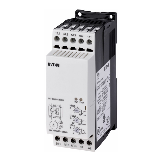
1 Device series DS7 1.1 Front View 1 Device series DS7 1.1 Front View The following two devices are used as examples of the DS7 series: • DS7-340SX032N0-N (left) – without SmartWire-DT interface • DS7-34DSX032N0-D (right) with SmartWire-DT interface Figure 1:... -
Page 16: System Overview
1 Device series DS7 1.3 System overview 1.3 System overview The following figure shows a DS7 soft starter together with (optional) accessories. ① ② ③ SWD 4-8S F2-5 SW D4- 8SF 2 SW D4- 8SF 2 + 15V ④ ⑤... -
Page 17: Description
1 Device series DS7 1.4 Description 1.4 Description 1.4.1 DS7-340…, DS7-342… The following drawing shows a DS7 soft starter (without SmartWire-DT) of size 2. ① ⑧ ② ⑦ ⑥ ③ ⑤ ④ Figure 3: Description of the DS7-34…-N soft starter... -
Page 18: Ds7-34D
1 Device series DS7 1.4 Description 1.4.2 DS7-34D… The following drawing shows a DS7-34D… soft starter with a SmartWire-DT connection (hereafter referred to with the abbreviation DS7-SWD) of size 2. ① ⑫ ② ⑪ ③ ⑩ ⑨ ⑧ ⑦ ④... -
Page 19: Key To Part Numbers
1 Device series DS7 1.5 Key to part numbers 1.5 Key to part numbers The soft starters of the DS7 series are assigned part numbers according to the following key to part numbers: DS7 - 3 Explanation Instance: N = no option... - Page 20 Control voltage and Control signals: 2 = 120/230 V AC Mains supply voltage: 4 = 400 V (200 - 480 V) Supply phases: 3 = three-phase incoming unit Soft starter series: Drives motor starter, Generation 7 DS7 Soft starter 09/16 MN03901001Z-EN www.eaton.com...
-
Page 21: Checking The Delivery
The DS7 series soft starter are carefully packed and prepared for shipment. These devices should only be shipped in their original packaging with suitable transportation materials. - Page 22 1 Device series DS7 1.6 Checking the Delivery The part no. on the nameplate indicates the specific DS7 soft starter version corresponding to the unit. In the figure below, the following letters are used to provide the following information: •...
-
Page 23: Technical Data
2) IEC: Mains voltage = Motor voltage (at load) 230 V, 400 V 3) Reduced overload current acc. to UL 508C 4) Mains voltage 208 V / 240 V / 480 V ↔ motor voltage 200 V / 230 V / 460 V DS7 Soft starter 09/16 MN03901001Z-EN www.eaton.com... - Page 24 4) Mains voltage 208 V / 240 V ↔ motor voltage 200 V / 230 V → When using single-phase AC motors, the rated operational current will depend on the system frequency and the capacitor being used. Example: 240 V, 50/60 Hz, 1.5/2.1 A 1300/1350 rpm, 5.0 μF CAP DS7 Soft starter 09/16 MN03901001Z-EN www.eaton.com...
-
Page 25: General Data
5 with size 3, size 4 Relay depending on variant 1 with size 1 (non-isolated) 2 with size 2, 3, 4 (potential-free) 2 at DS7 without SWD (DS7-340…, DS7-342…) 3 at DS7 without SWD (DS7-34D…) DS7 Soft starter 09/16 MN03901001Z-EN www.eaton.com... -
Page 26: Device Version
1.7.3 Device version DS7 soft starters are classified in accordance with IEC 60947-4-2:2011, Table 1 (Functional possibilities of semiconductor motor control devices). The soft starters belonging to the DS7 series correspond to device version 1. Figure 8: Semi-conductor – Motor – Controlgear 1.7.4 Permissible environmental conditions... -
Page 27: Maintenance And Inspection
Motor cable According to manufacturer specifications, no later than 5 years DS7 soft starters are not designed in such a way as to allow for the replacement or repair of their individual components or sub-assemblies. DS7 Soft starter 09/16 MN03901001Z-EN www.eaton.com... -
Page 28: Storage
Conditions Eaton Industries GmbH. Hotline After Sales Service +49 (0) 180 5 223822 (de, en) AfterSalesEGBonn@eaton.com 1.12 Disposal The soft starters of the DS7 series can be disposed of as electronic scrap in accordance with national regulations. DS7 Soft starter 09/16 MN03901001Z-EN www.eaton.com... -
Page 29: Selection Criteria
In the case of single-phase AC motors (→ page 20), the selection must be based on the mains voltage (= the motor’s rated operating voltage) and the rated motor current for the specific line frequency. DS7 Soft starter 09/16 MN03901001Z-EN www.eaton.com... -
Page 30: Function
1 Device series DS7 1.14 Function 1.14 Function DS7 soft starters use phase control for controlling the voltage of the supply network smoothly from an adjustable start value up to 100 % of the rated value U . This voltage control enables the inrush current of a three-phase asynchronous motor to be limited and its starting torque to be considerably reduced. - Page 31 = Rated speed at the operating point ① = adjustable current limitation When used together with a PKE motor-protective circuit-breaker and a SmartWire-DT connection, size 1 and size 2 DS7-34D…-D soft starters can also be used to start motors with current limiting ①. 0.25 0.75...
- Page 32 1 Device series DS7 1.14 Function The mechanical apparatus of a drive unit controlled with a DS7 soft starter are therefore accelerated very smoothly. This has a positive effect on the lifespan, operating behavior and operating processes, and prevents any adverse effects such as •...
- Page 33 1 Device series DS7 1.14 Function As well as the time-controlled startup of a motor, the DS7 soft starter also enables a time-controlled reduction of the motor voltage and thus a controlled stopping of the motor. This type of stop function is primarily used for pumps in order to prevent pressure waves (water impact).
- Page 34 Eaton (Moeller) for phase control (PCT/EP00/12938, 19.12.2000) prevents DC components and ensures optimum startup behavior. This control is integrated in the DS7 soft starters and is active during the start (t-Start) and stop ramp (t-Stop). DS7 Soft starter 09/16 MN03901001Z-EN www.eaton.com...
- Page 35 New process from Eaton (Moeller): Asymmetrical control without DC components → With single-phase connected three-phase motors with capacitors (Steinmetz circuit), system conditions always cause an elliptical rotating field which cannot be completely compensated by the asymmetrical trigger control. DS7 Soft starter 09/16 MN03901001Z-EN www.eaton.com...
- Page 36 1 Device series DS7 1.14 Function DS7 Soft starter 09/16 MN03901001Z-EN www.eaton.com...
-
Page 37: Engineering
The relevant procedure is described in the manual MN03902001Z-EN (“Design of soft soft starters”) and applies generally to all Eaton soft starters. The necessary key data of the DS7 soft starter series that is also required for this design (rated operational current, overload capacity, root mean square current at nominal switching frequency) is provided in the Appendix in the technical data. -
Page 38: Emc Compliance
The IEC EN 60947-4-2 product standards allows for the limit value classes and measurement methods of the IEC/CISPR11 or EN 55011 standard. No other measures are required on the DS7 soft starter for the limitation of interference emission in accordance with EN 55011 limit value class A (industrial environment). -
Page 39: Power Connection
At the output of the soft starter (terminals 2T1, 4T2, 6T3) you must not • Connect any capacitive load (e.g. phase compensation capacitors), • Connect several soft starters in parallel, • Feed a mains voltage or a voltage from a variable frequency drive or other voltage source. DS7 Soft starter 09/16 MN03901001Z-EN www.eaton.com... -
Page 40: Emergency Switching Off
In addition to the safety devices for type 1 coordination, superfast semiconductor fuses are required for type 2 coordination. These fuses will protect the thyristors in the DS7 soft starter from damage in the event of a short-circuit on the output terminals (2T1, 4T2, 6T3 motor connections). -
Page 41: Residual Current Circuit-Breaker (Rcd)
They prevent dangerous and fatal injuries caused by electrical accidents and also serve as fire prevention. Size 1 and 2 soft starters of the DS7 series have no connection to the earth potential (PE). In size 3 and 4, the DS7 soft starters have an exposed heat sink which must be connected with the earth potential (PE). -
Page 42: Motor Protection
Thermistor, PTC or semiconductor contactor protection in the motor winding with external signalling relay (EMT) → The combination of the motor protection variants ①, ② or ③ with the temperature monitoring variant ④ is also called full motor protection. DS7 Soft starter 09/16 MN03901001Z-EN www.eaton.com... -
Page 43: Ds7-Swd And Pke Motor-Protective Circuit-Breakers
Protecting the DS7 soft starter against overload • adjustable current limitation, • ZMR overload relay function (in the event of an overload, the DS7 soft starter will switch off the load, instead of the PKE motor-protective circuit-breaker doing so) •... -
Page 44: Cables, Contactors, Line Filters
PKE trip block. If the DS7-SWD soft starter is connected to a SmartWire-DT network, the DS7-SWD soft starter will transmit the data for the PKE trip block (currents) to a higher-level main controller (PLC). 2.10 Cables, contactors, line filters The cables used must meet the requirements of locally applicable regulations at the site of installation. -
Page 45: Motor Connection
4 kW motor output in a delta circuit (400/690 V). Do not connect three-phase motors with starpoint-earthing (star circuit) or motors with a neutral conductor connection to DS7 soft starters (see fig. 23), as one phase is always connected directly to mains voltage and will heat up the motor excessively. -
Page 46: Connection And Phase Sequence
Figure 24: Operating direction with view on motor shaft Mains Input 1L1, 3L2, 5L3 2T1, 4T2, 6T3 Output Motor Figure 25: Connection and direction in which power flows in DS7 soft starters DS7 Soft starter 09/16 MN03901001Z-EN www.eaton.com... -
Page 47: Delta Connection
2 Engineering 2.11 Motor connection For clockwise rotation, connect the motor and the DS7 soft starter to each other as follows: Table 9: Connection of Soft starters and motor Supply system Soft starter input Soft starter output Motor (Mains) (Input) -
Page 48: Actuation Of Resistive Loads
2 Engineering 2.11 Motor connection 2.11.4 Actuation of resistive loads DS7 soft starters can also be used to drive resistive loads (example: electrical heating elements). Q1 = Cable and cable protection Q21 = Soft starter I > I > I >... -
Page 49: Connection Of Ac Motors
2 Engineering 2.11 Motor connection 2.11.5 Connection of AC motors AC motors can also be operated with the DS7 soft starters series. Only the version of the three-phase asynchronous motor with a capacitor (Steinmetz circuit) is considered suitable for industrial use. -
Page 50: Long Motor Supply Cables
2.11.7 Parallel motor connection Several motors can be connected in parallel at the output of the DS7 soft starter. This does not, however, allow the behavior of the individual motors to be controlled. It must be taken into account that an even run-up of all motors cannot be ensured. -
Page 51: Connecting Motors
(approx. 6 to 8 times the rated motor current) and the current for the remaining motors. Otherwise, an overload will occur and the soft starter may be destroyed in the worst case. DS7 Soft starter 09/16 MN03901001Z-EN www.eaton.com... -
Page 52: Cascade Circuit
2 Engineering 2.11 Motor connection 2.11.9 Cascade circuit The DS7 soft starters can be used to start several motors in sequence. This requires the observance of a specific switching sequence (→ section 7, “Connection examples”). → When starting several motors with one soft starter the thermal load of the soft starter (starting frequency, current load) must be taken into account. -
Page 53: Bypass Circuit
(capacitors)! This would damage the soft starter. 2.11.11 Bypass circuit → Devices of the DS7-34… series are already equipped with integrated bypass contacts. An external bypass is therefore not required. 2.11.12 Bypass circuit for emergency operation In pump applications there is a frequent requirement for the bypass contactor to provide facility for emergency operation. - Page 54 Q31 = Motor contactor F3 = Semiconductor fuse for type 2 coordination, in addition to Q1 M1 = Motor Figure 32: Power section – example: DS7 ≧ 41 A with bypass emergency operation DS7 Soft starter 09/16 MN03901001Z-EN www.eaton.com...
-
Page 55: Repair And Maintenance Switch
This prevents voltage from being applied and the motor from being started by accident during repair and maintenance work. The DS7 soft starter has a two-phase circuit with semiconductor elements in the power section, one phase is always connected through directly. DANGER ... - Page 56 2 Engineering 2.11 Motor connection I > I > I > Start/Stopp Figure 34: Connecting example of the DS7 soft starter (FS3, FS4) with a maintenance/manual override switch for the safe isolation for motor connection DS7 Soft starter 09/16 MN03901001Z-EN www.eaton.com...
-
Page 57: Loading Conditions
2.12 Loading conditions 2.12 Loading conditions DS7 soft starters are designed for a standard duty cycle as defined for AC-53a in product standard IEC/EN 60947-2-1. This means: 3-fold overcurrent for 5 seconds with a duty factor of 75 % and 10 starts per hour. -
Page 58: Different Overload Current
The example shown here is a 30 kW motor (400 V, 55 A) with an assigned DS7-34xSX055… soft starter (55 A, rated operational current = motor current). The maximum starting current of 165 A (I ) can be achieved for 5 s at 10 starts per hour (overload factor X = 3). - Page 59 200 A = 165 A Figure 36: Overload current X = 3 with DS7-34xSX055… soft starter If a higher overload current (e.g. X ~ 5) is required, the start conditions stated here require a DS7-34xSX100… (100 A) soft starter. The I value here is 300 A for 5 s at 10 starts per hour.
-
Page 60: Configuration Options Of Ds7
DILM12-XMCP/T or The number of starts per ZB…12/ZB32… hour must be multiplied by + DS7-FAN-032 (fan) the factor 4, i.e. 1, 10, 20 → 4, 40, 80 → Example V. (page 58) DS7 Soft starter 09/16 MN03901001Z-EN www.eaton.com... -
Page 61: Design With Different Load Cycles
2.13 Design with different load cycles 2.13 Design with different load cycles The DS7 soft starter is designed for a standard load cycle in accordance with AC-53a of the IEC/EN 60947-2-1 product standard. This means: 3-fold overcurrent for 5 seconds with a duty factor of 75 % and 10 starts per hour. -
Page 62: Example Of Other Load Cycles
15 s 10 s 18 A 27 A 36 A 45 A III. Combination of xStart components without device fan The overload curve of the DS7-34xSX007 soft starter applies to DS7-34xSX009…. 30 s 10/h 25 s 20/h 20 s 15 s... - Page 63 = 5 s and X = 3 a maximum of four starts per hour are permissible here. → The overload curves of the individual DS7 soft starter variants are listed in the Appendix on page 219. DS7 Soft starter 09/16 MN03901001Z-EN www.eaton.com...
- Page 64 2 Engineering 2.15 Example of other load cycles DS7 Soft starter 09/16 MN03901001Z-EN www.eaton.com...
-
Page 65: Installation
IL03902004Z: For size 2 devices (16 – 32 A device current) • IL03902005Z: For size 3 and 4 devices (41 - 200 A device current) 3.2 Mounting positions The maximum permissible angle of inclination for all soft starters of the DS7 is 30°. F 30˚ F 30˚... -
Page 66: Flush Mounting In Control Panel
Improper handling or use of the wrong tools may cause damage to the soft starter. The Soft starter DS7 is only designed for use as built-in device. Take sufficient counter measures in the case of: •... -
Page 67: Increased Cooling
(K) of temperature rise after +40 °C with device fan (DS7-FAN-…) 3.3.1 Increased cooling Cooling air circulation on the DS7 soft starter can be improved by using an optional DS7-FAN-… device fan This makes the following possible: •... - Page 68 3.3 Flush mounting in control panel 3.3.1.1 DS7-FAN-032 device fan The optional DS7-FAN-032 device can be fitted on the rear of the soft starter sizes 1 and 2 (i.e. devices up to 32 A). Figure 40: Fitting the fan (basic principle) To do this, open the mounting space in the enclosure.
- Page 69 When inserting the device fan, make sure not to damage the fan’s plug connections (pins) or connection cables. To mount the DS7-FAN-032 device fan, place it on the bottom edge of the housing (plug connectors at the top left) and fully insert without the use of force.
- Page 70 3.3 Flush mounting in control panel 3.3.1.2 Device fan DS7-FAN-100 / DS7-FAN-200 The optional DS7-FAN-100 and DS7-FAN-200 fans are mounted on the back of the DS7 soft starter. They are fastened onto the heat sink using four screws. Figure 44: Fitting the fan (basic principle) 2 Nm (17.7 lb-in)
- Page 71 Figure 48: Remove the cover → The blanking plate can not be refitted. If you remove the device fan, make sure to cover the plug connection with a suitable material (by masking it with electrical tape, for example). DS7 Soft starter 09/16 MN03901001Z-EN www.eaton.com...
- Page 72 (pins) or connection cables. → The device fan is temperature-controlled, always runs during ramp times (t-Start, t-Stop), and will continue to run until the heat sink cools down again. The fan is then automatically switched off. DS7 Soft starter 09/16 MN03901001Z-EN www.eaton.com...
-
Page 73: Mounting Instructions (Bg 1 And Bg 2)
→ An installation clearance of 25 mm must be maintained in front of size 1 and size 2 (up to 32 A) DS7 soft starters. A top and bottom clearance of 75 mm each is required. If the clearances are smaller, derating will be necessary or it will be necessary to use the optional DS7-FAN-032 fan. - Page 74 3.3 Flush mounting in control panel 3.3.2.2 Fitting on mounting plate The DS7 soft starters are screwed onto the switch cabinet wall (mounting plate). The control signal terminals and the operator control and display elements must face the front. The screw fixing is completed with at least two diagonally arranged flat head screws.
- Page 75 3 Installation 3.3 Flush mounting in control panel 3.3.2.3 Surface mounting on mounting rail Place the DS7 soft starter onto the mounting rail from above [1], push down [2] and let it snap into position. Removing it requires using a little force from...
- Page 76 ③ Figure 55: Mounting of size 1 devices (up to 12 A) The size 1 DS7 soft starter (up to 12 A) can be connected directly to a PKZ or PKE motor-protective circuit-breaker. This electronic motor-starter combination can be mounted directly on a mounting plate, a mounting rail or on busbar adapter.
- Page 77 3 Nm ① Figure 56: Mounting of size 2 devices (up to 32 A) • PKZM0-XM32DE electric contact module for connecting a DS7 soft starter directly to a = ① PKZ or PKE motor-protective circuit-breaker • optional, variant 1: PKZM0-XC45L/2 top-hat rail adapter = ②...
-
Page 78: Mounting Instructions (Size 3 And 4)
3.3.3.1 Free surrounding areas With sizes 3 and 4 (41 to 200 A), a mounting clearance of 5 mm to the front of the DS7 soft starter must be maintained. A top and bottom clearance of 75 mm each is required. - Page 79 ≧ 35 mm (3.38“) 3.3.3.2 Fitting on mounting plate The DS7 soft starters in sizes 3 and 4 must be screw fastened vertically on a heat conductive non-combustible mounting plate. The control signal terminals and the operating and indication elements must face the front.
- Page 80 → The drilling dimensions will be different when using optional device fan DS7-FAN-100 or DS7-FAN-200. Refer to the dimension drawings on page 232. Figure 60: Fitting on mounting plate, DS7 soft starter (sizes 3 and 4) Part no. inch lb-in DS7-34…SX041N0...
-
Page 81: Electrical Installation
DANGER Before connecting the DS7 soft starter’s power terminals to voltage for the first time, the control voltage needs to be applied in order to ensure that the internal bypass contacts will open. -
Page 82: Connection To Power Section
PE → PE For frame size 1, the PZD2 motor connection can optionally be implemented with a DILM12-XMCP/T motor outgoer plug. 5.3 mm (0.21’’) Figure 61: Pluggable motor connection for size 1 DS7 Soft starter 09/16 MN03901001Z-EN www.eaton.com... - Page 83 DS7…135… 2 x 9 x 0.8 mm - 10 x 16 x 0.8 mm 10 x 0.63 x 0.03 inch DS7…160… 1.6 - 8 9 -16 0.006 - 0.31 0.87 0.35 - 0.63 DS7…200… DS7 Soft starter 09/16 MN03901001Z-EN www.eaton.com...
-
Page 84: Connection In Control Section
0.6 x 3.5 3.54 2 x 0.5 - 1.0 2 x 0.5 - 0.75 2 x 21 - 20 0.24 0.6 x 3.5 3.54 DS7…135… DS7…160… DS7…200… Figure 62: Example for size 3 and 4 DS7 Soft starter 09/16 MN03901001Z-EN www.eaton.com... - Page 85 460/480 V AC 460/480 V AC Figure 63: Laying control cables a Power cable L1, L2, L3, U, V, W b Control cables: +U , -U , +A1, -A2, EN, 13, 14, 23, 24 DS7 Soft starter 09/16 MN03901001Z-EN www.eaton.com...
-
Page 86: Connection To Smartwire-Dt
3.4.3.1 PKE32-COM communication cable To connect a PKE motor-protective circuit-breaker (sizes 1 and 2 only) with a PKE-XTU(W)A-… trip block to a DS7-SWD soft starter (size 1 or size 2), you will need a PKE32-COM communications cable. This cable will serve as a communication link between the DS7-SWD soft starter and the PKE-XTU(W)A-…... - Page 87 In order to connect a PKE motor-protective circuit-breaker with a PKE32-COM communication cable, the following additional installation steps for the DS7-SWD soft starter are required on top of the standard installation procedure (→ figures 55 and 56): ▶ Remove the empty module on the PKE basic device.
- Page 88 3 Installation 3.4 Electrical Installation ▶ Remove the communication interface cover on the DS7-SWD soft starter (please lift the cover!) and connect the PKE32-COM communication cable. ▶ Put the communication interface cover back in place. DS7 Soft starter 09/16 MN03901001Z-EN www.eaton.com...
-
Page 89: Functions Of Control Signal Terminals
✓ Control input start/stop (positive pole) Same voltage level as +U Low level: 0 - 3 V; High level: 4.6 – +U Current drain: DS7-340…: 1.6 mA at 24 V DS7-342…: 4 mA at 230 V ✓ ✓ ✓ ✓... -
Page 90: Control Section Power Supply
3 Installation 3.4 Electrical Installation 3.4.5 Control section power supply The control section in the DS7 soft starter can be powered with the following voltages using terminals +U (sizes 2, 3, and 4) or +U /-A2 (size 1): • 24 V DC/AC at DS7-340…... -
Page 91: Relay Contacts
3 Installation 3.4 Electrical Installation 3.4.8 Relay contacts The soft starters of the DS7 series are provided with one or two relays with an N/O contact depending on the current range. The relays are galvanically isolated from the power section. - Page 92 Ready for operation b operation → Soft starters DS7 of the size 1 (up to 12 A) have no RUN / READY relay. The TOR relay in this size has different terminal designations and has the same reference potential (-A2) as the control voltage.
-
Page 93: Relay Contacts - Connection Examples
+A1 -A2 +A1 -A2 ① ① ② DS7-340…: 24 V AC DS7-340…: 24 V DC DS7-342…: 120 - 230 V AC Size 2 (16 - 32 A) – Isolated relay contacts RUN/READY +A1 -A2 13 ① ② ③ DS7-340…: 24 V AC L (+) DS7-342…: 120 - 230 V AC... -
Page 94: Block Diagrams
The number and arrangement of the control terminals in the individual sizes vary according to the power. Size 1 (4 – 12 A) Size 2 (16 – 32 A) Size 3 and 4 (41 – 200 A) Figure 69: Block diagrams DS7 Soft starter 09/16 MN03901001Z-EN www.eaton.com... -
Page 95: Insulation Test
3 Installation 3.6 Insulation test 3.6 Insulation test The soft starters of the DS7 series are tested, delivered and require no additional testing. CAUTION On the control signal and the connection terminals of the soft starter, no leakage resistance tests are to be performed with an insulation tester. - Page 96 3 Installation 3.6 Insulation test DS7 Soft starter 09/16 MN03901001Z-EN www.eaton.com...
-
Page 97: Operation
4 Operation 4.1 Checklist for commissioning 4 Operation 4.1 Checklist for commissioning Before commissioning the DS7 soft starter, make sure to check the following (using the check list): No. Activity Note Installation and wiring completed as specified in the relevant instructional leaflets (→... - Page 98 Control voltage U must match the relevant voltage specifications for the DS7 soft starter (see nameplate specifications). DS7-SWD The SmartWire-DT address for the DS7-SWD soft starter will be assigned automatically by the gateway when the configuration button is pressed. DANGER ...
-
Page 99: Commissioning
4.2 Commissioning 4.2 Commissioning The factory settings for DS7-34… soft starters are configured in such a way as to allow a suitably rated 4-pole standard motor to be run in typical soft starter applications without the need for any additional adjustments. -
Page 100: Extended Functionality
About 65 % (do not select the maximum or the minimum value) If the potentiometers are set to settings other than the ones shown above, the DS7 soft starter will keep its configuration, i.e., the relay function and phase sequence detection function will keep behaving the same way as the last time before the device was switched off. - Page 101 Possible reasons for this include: • The functionality was not configured fast enough (i.e., within the 2-second configuration period). • The configuration steps were not carried out with the required precision. • t-Start and U-Start were adjusted simultaneously. DS7 Soft starter 09/16 MN03901001Z-EN www.eaton.com...
-
Page 102: Potentiometer Settings
U-Start, t-Start, and t-Stop respectively. Aside from these potentiometer settings, no additional settings or prompts are required in order to run the soft starters. When using DS7-SWD soft starters, these potentiometer settings can be adjusted by means of parameters. →... - Page 103 In this case, the t-Start setting must be reduced in such a way that any unnecessary motor heating will be avoided. → Excessively short start times may lead to the internal relay being overloaded. DS7 Soft starter 09/16 MN03901001Z-EN www.eaton.com...
- Page 104 With stop ramp (+A1 = OFF, t-Stop > 0) b Without stop ramp (+A1 0 OFF, t-Stop = 0 s) or via control signal terminal EN (in the case of sizes 3 and 4) or via SmartWire-DT with t-Stop = 0 DS7 Soft starter 09/16 MN03901001Z-EN www.eaton.com...
- Page 105 In the case of size 3 and size 4 devices without SmartWire-DT, the EN (Enable) signal must remain on without change. For devices with SmartWire-DT → chapter 8, “SmartWire-DT”. NOTICE Excessively short ramp times may lead to the relay being overloaded! DS7 Soft starter 09/16 MN03901001Z-EN www.eaton.com...
-
Page 106: Examples
U-Start (%) t-Start (s) t-Stop (s) t-Start [s] U-Start [%] t-Stop [s] Application example J l 0 Low flywheel mass Conveyor belt with loose belt Roller conveyers Centrifugal pump Fan general (building) with belt drive DS7 Soft starter 09/16 MN03901001Z-EN www.eaton.com... - Page 107 Figure 74: Recommended settings per application → When using DS7-SWD soft starters, these settings can be adjusted using parameters (PNU) (→ section 8.9.5.2, “Acyclic DS7 soft starter data”, page 186. DS7 Soft starter 09/16 MN03901001Z-EN www.eaton.com...
-
Page 108: Commissioning Instructions
If there will be frequent starts during normal operation, the soft starter may have to be oversized under certain circumstances and/or optional fan DS7-FAN… may have to be used. For more information, refer to the “Technical data” appendix. -
Page 109: Start The Motor
One phase to the motor is internally bridged, which means that a supply phase is still directly present at the motor even when it is switched off. Danger in the event of contact! DS7 Soft starter 09/16 MN03901001Z-EN www.eaton.com... -
Page 110: Led Indicators
4 Operation 4.8 LED indicators 4.8 LED indicators The RUN and Error LEDs are used to indicate the DS7 soft starter’s operating state. The shades of gray below have the following meanings in the following table: = Green RUN LED... - Page 111 LED indicator modes. → When control voltage U is switched on, the DS7 soft starter starts an initialization routine. During this phase, both LEDs (RUN, Error) may light up simultaneously for a short time. DS7 Soft starter 09/16 MN03901001Z-EN www.eaton.com...
- Page 112 The actual acceleration time will depend on the load and the motor, and even with the same identical t-Start setting may result in different times if the loads change. DS7 Soft starter 09/16 MN03901001Z-EN www.eaton.com...
-
Page 113: Operating State Signals
4 Operation 4.8 LED indicators 4.8.1 Operating state signals The DS7 soft starter’s operating states are indicated on the basic device by means of two LEDs (RUN, Error): • RUN = Operating signal (green) • Error = fault message (red) -
Page 114: Signals In Ds7-34D
4.8.2 Signals in DS7-34D…-D In conjunction with SmartWire-DT, the RUN and Error LEDs are used to output the following signals in devices belonging to series DS7-34D…-D (in addition to → section 4.8.1, “Operating state signals”): Table 19: LED signals in DS7-34D…-D... -
Page 115: Messages In The Event Of Faults
Thyristor fault Failure of one or several thyristors in the power section Phase failure Phase fault in the mains voltage (L1, L2, L3) Bypass fault (Relay contact faulty) Fault in the control voltage (U DS7 Soft starter 09/16 MN03901001Z-EN www.eaton.com... -
Page 116: Error Messages
860.21 860.20 860.22 L3 Error Figure 77: Error messages → In the case of DS7-34D…-D devices, error messages will be transmitted individually and with additional information via the SWD connection (→ chapter 8, “SmartWire-DT”). DS7 Soft starter 09/16 MN03901001Z-EN www.eaton.com... - Page 117 Heat up the room or control panel and monitor (860.2) – only sizes 3 and 4 when EN is activated the temperature Phase sequence error Incorrect phase sequence The power supply phases are Swap the phases (860.22) connected in the wrong sequence. DS7 Soft starter 09/16 MN03901001Z-EN www.eaton.com...
- Page 118 (mains supply voltage). Proper operation can only be ensured within the permissible limits of 50/60 Hz ± 5 %. DS7 Soft starter 09/16 MN03901001Z-EN www.eaton.com...
-
Page 119: Diagnostics
5 Diagnostics → The housing of the DS7 soft starter does not have to be opened for diagnostics and fault detection tasks. The design of the soft starter does not allow for it to be opened, and this may cause lasting damage to the housing. -
Page 120: Motor Consuming Too Much Current
Certain error messages can be acknowledged during operation if • The control signal on terminal +A1 is switched off and then back on • The corresponding bits are set again if SmartWire-DT-based control is being used DS7 Soft starter 09/16 MN03901001Z-EN www.eaton.com... -
Page 121: Parameterization
DS7 soft starters (DS7-34D…-D) are described in → chapter 8, “SmartWire-DT”. 6.2 Default settings of the basic device The soft starters of the DS7 series are factory set so that no settings are required for standard applications. The most important default settings are listed below. - Page 122 6 Parameterization 6.2 Default settings of the basic device DS7 Soft starter 09/16 MN03901001Z-EN www.eaton.com...
-
Page 123: Connection Examples
24 V AC/DC, 120/230 V AC (–) U Figure 78: Standard connection without soft stop L1, L2, L3 + A1 T1, T2, T3 Start (13/14) t-Start Figure 79: Flow diagram - without soft stop DS7 Soft starter 09/16 MN03901001Z-EN www.eaton.com... -
Page 124: Connection With Soft Stop Ramp
24 V AC/DC, 120/230 V AC (–) U Figure 80: Standard connection with Soft stop L1, L2, L3 (Start/Stop) T1, T2, T3 Start (13/14) t-Stop t-Start Figure 81: Flow diagram – with soft stop DS7 Soft starter 09/16 MN03901001Z-EN www.eaton.com... -
Page 125: Standard Connection With Upstream Mains Contactor And Soft Stop Ramp
Standard connection with mains contactor L01/L+ ① Control section for the mains contactor Q11 During operation, the deactivation via S1 causes an uncontrolled stop of the motor. ① L00/L- Figure 83: Control section with mains contactor DS7 Soft starter 09/16 MN03901001Z-EN www.eaton.com... -
Page 126: Simple Change Of Rotation
When in the R position (FWD), S3 will use contact 23/24 to apply the enable signal ① to the DS7 soft starter (+A1 control signal terminal). The rotation is reversed with S3 via the zero position (off) to position L (REV). -
Page 127: Rotation Direction Reversal With Soft Stop Ramp
> t-Stop Figure 87: Control section Bidirectional operation → The control voltages (+U ) of the DS7 soft starter and the contactor control must have the same potential: 24 V DC/AC or 120/230 V AC DS7 Soft starter 09/16 MN03901001Z-EN www.eaton.com... -
Page 128: Reversing The Direction Of Rotation With Msc-R
L (+) ③ 1.53 1.54 ① REV II ① Assembled control station FWD I ② Reversing starter ③ Standard auxiliary contact ② t > t-Stop N (-) Figure 89: Control section bidirectional operation with ramp DS7 Soft starter 09/16 MN03901001Z-EN www.eaton.com... - Page 129 RUN signal. The reset time must be greater than the stop time (t-Stop) set on the DS7 soft starter. Switching to the other operating direction is only possible after the value set here has elapsed. The soft stop is also active here after an emergency-stop command.
-
Page 130: Connection For Ac Motor
(example for ① : DILM7 + DILM12-XP1) Q21 = Soft starter - A2 + A1 S3 = Start/stop-switch (+) U 24 V AC/DC, 120/230 V AC (–) U Figure 90: AC motor in Steinmetz circuit DS7 Soft starter 09/16 MN03901001Z-EN www.eaton.com... -
Page 131: Size 2 (16 - 32 A)
24 V AC/DC, 120/230 V AC (–) U Figure 91: Standard connection without soft stop L1, L2, L3 + A1 (23/24) T1, T2, T3 Start (13/14) t-Start Figure 92: Flow diagram – without soft stop DS7 Soft starter 09/16 MN03901001Z-EN www.eaton.com... -
Page 132: Connection With Soft Stop Ramp
24 V AC/DC, 120/230 V AC (–) U Figure 93: Standard connection with soft stop L1, L2, L3 (Start/Stop) (23/24) T1, T2, T3 Start (13/14) t-Stop t-Start Figure 94: Flow diagram – with soft stop DS7 Soft starter 09/16 MN03901001Z-EN www.eaton.com... -
Page 133: Standard Connection With Upstream Mains Contactor And Soft Stop Ramp
During operation, the deactivation via S1 causes an uncontrolled stop of the motor. ① S1 = Off S2 = On S3 = Soft stop S4 = start L00/L- Figure 96: Control section with mains contactor DS7 Soft starter 09/16 MN03901001Z-EN www.eaton.com... -
Page 134: Rotation Direction Reversal With Soft Stop Ramp
Q12 = mains contactor REV (anticlockwise rotating field) F3 = optional semiconductor fuse for type 2 coordination in addition to Q1 (+) U 24 V AC/DC, 120/230 V AC (–) U Figure 97: Rotation direction reversal with ramp DS7 Soft starter 09/16 MN03901001Z-EN www.eaton.com... - Page 135 Control section bidirectional operation The RUN relay (Q21:23/24) only enables the rotation direction change (phase change) after the soft stop time (t-Stop) has elapsed. The soft stop is also active here after an emergency-stop command. DS7 Soft starter 09/16 MN03901001Z-EN www.eaton.com...
-
Page 136: Size 3 And 4 (41 - 200 A)
24 V AC/DC, 120/230 V AC (–) U Figure 99: Standard connection without soft stop L1, L2, L3 + A1 (23/24) T1, T2, T3 Start (13/14) t-Start Figure 100: Flow diagram – without soft stop DS7 Soft starter 09/16 MN03901001Z-EN www.eaton.com... -
Page 137: Connection With Soft Start Ramp
(–) U Figure 101: Standard connection with Soft stop L1, L2, L3 Q1, EN (Start/Stop) (23/24) T1, T2, T3 Start (13/14) t - Start t - Stop Figure 102: Flow diagram – with soft stop DS7 Soft starter 09/16 MN03901001Z-EN www.eaton.com... -
Page 138: Standard Connection With Upstream Mains Contactor And Soft Stop Ramp
① The RUN relay (Q21:23/24) monitors the switching operation (no undefined operating state). S1 = Off S2 = On S3 = Soft stop S4 = start L00/L- Figure 104: Control section with mains contactor DS7 Soft starter 09/16 MN03901001Z-EN www.eaton.com... -
Page 139: Rotation Direction Reversal With Soft Stop Ramp
Q12 = mains contactor REV (anticlockwise rotating field) F3 - Optional semiconductor fuse for type 2 coordination, in addition to Q1 (+) U 24 V AC/DC, 120/230 V AC (–) U Figure 105: Rotation direction reversal with ramp DS7 Soft starter 09/16 MN03901001Z-EN www.eaton.com... - Page 140 ② without Soft stop The RUN relay (Q21:23/24) only enables the rotation direction change (phase change) after the soft stop time (t-Stop) has elapsed. The soft stop is also active here after an emergency-stop command. DS7 Soft starter 09/16 MN03901001Z-EN www.eaton.com...
-
Page 141: Compact Motor Starter With Maintenance Switch
Q21 = DS7 soft starter Q32 = Maintenance switch (local) F3 = optional semiconductor fuse for type 2 coordination (in addition to Q1) M1 = Three-phase motor Start/Stopp Figure 107: Motor starter with repair/maintenance switch DS7 Soft starter 09/16 MN03901001Z-EN www.eaton.com... -
Page 142: Ds7 Soft Starter And Nzm Circuit-Breaker With Emergency-Stop Function To Iec/En 60204 And Vde 0113 Part 1
7 Connection examples 7.3 Size 3 and 4 (41 – 200 A) 7.3.6 DS7 soft starter and NZM circuit-breaker with emergency-stop function to IEC/EN 60204 and VDE 0113 Part 1 = EMERGENCY SWITCHING OFF Q1 = Cable and motor protection ①... -
Page 143: Bypass Circuit For Emergency Operation
7.3 Size 3 and 4 (41 – 200 A) 7.3.7 Bypass circuit for emergency operation → Devices of the DS7-34… series are equipped with integrated bypass contacts. External bypass contacts are therefore not required for standard operation. In pump applications the bypass circuit is often required to provide emergency operation capability. - Page 144 M1 = Motor Figure 110: Power section with bypass emergency operation – (pump operation) → The control system shown here can also be used for the DS7 soft starters in size 2 (16 - 32 A). DS7 Soft starter 09/16 MN03901001Z-EN www.eaton.com...
-
Page 145: Starting Several Motors Sequentially With A Soft Starter
(i.e. the soft starter must be designed with an accordingly higher load cycle). → Due to the thermal design of the DS7 soft starters, we recommend the use of an (optional) fan when using a DS7 series device for starting several motors. - Page 146 Mn = Motor (1, 2, n) → The control system shown here can also be used for the DS7 soft starters in size 2 (16 to 32 A). → The “thermal motor protection” (Q13, Q23, Qn3) can also be ensured with current transformer-operated overload relays (see →...
- Page 147 K(n-1)2 Q(n-1)1 L00/L- Figure 113: Actuation, motor cascade, part 2 a Motor 1 b Motor 2 c Motor n The N/C contact S3 is required if motors also have to be switched off individually. DS7 Soft starter 09/16 MN03901001Z-EN www.eaton.com...
- Page 148 7 Connection examples 7.3 Size 3 and 4 (41 – 200 A) DS7 Soft starter 09/16 MN03901001Z-EN www.eaton.com...
-
Page 149: Smartwire-Dt
SmartWire-DT, and their parameters can be configured via SmartWire-DT as well. Depending on the specific model and field of application, DS7-SWD soft starters can be combined and operated together with an NZM circuit- breaker, a PKZ motor-protective circuit-breaker, or a PKE electronic motor- protective circuit-breaker as a safety device. -
Page 150: Profiles For Ds7-Swd
DS7-SWD PKE3 PKE profile 3, start/stop bit for DS7 DS7-SWD PKE1-8Bit PKE profile 1, control data for the DS7 in one extra byte (command) at the end of the frame DS7-SWD PKE2-8Bit PKE profile 2, control data for the DS7 in one extra byte (command) -
Page 151: Abbreviations
SmartWire-DT 8.5 SmartWire-DT response time The DS7-SWD soft starter’s response time on a SmartWire-DT system is about 150 ms. When there are two stations, the response time will increase by about 50 ms; when there are 50, by about 400 ms. -
Page 152: Interoperability
Windows 2000 (SP 4), Windows XP, Windows Vista (32-bit) or Windows 7 and relieves you of the planning work required for an SWD topology. DS7-SWD soft starters can be used in SWD-Assist version V 1.60 and higher. DS7 Soft starter 09/16 MN03901001Z-EN www.eaton.com... -
Page 153: Part Numbers
DS7-34DSX200N0-D 8.8 Replacing soft starters If you replace a DS7-SWD soft starter in a supply system, you will have to press the configuration button after replacing it and switching on the voltage. This ensures that the new soft starter is assigned a network address. -
Page 154: Programming
SmartWire-DT system. The number of cyclic data is variable and is defined with the aid of profiles. DS7-SWD soft starters (with or without a PKE motor-protective circuit- breaker) are designed in such a way as to match the following profiles and meet the following standards: •... - Page 155 8.9.2.1 Local – State diagram for sizes 1 and 2 If a size 1 or 2 DS7-SWD soft starter is used with PNU 928.0 = 0, the state diagram shown below will apply. The transition from S3 to S4 is automatic.
- Page 156 8.9.2.4 Network – State diagram for profiles 1, 2, 3 If profile 1, 2 or 3 (DS7 as Contactor) is used with PNU 928.0 = 1, the state diagram shown below will apply. The transition from S3 to S4 is automatic.
- Page 157 Bit 3 = 1; Bit 4 = 0 Top of Ramp Ramp Down Bit 0 = 0 (EN_Set) S4.4: TOR Operation Bit 3 = 1; Bit 4 = 1 Figure 120: State diagram: Network – S4 (profiles 4, 5, 6, 10) DS7 Soft starter 09/16 MN03901001Z-EN www.eaton.com...
- Page 158 Bit 0 = 0 Bit 2 = 0 (EN_Op) (EN_Op) (OnOff) (OnOff) (Off3) S4: Operation Bit 0, 1, 2 = 1; Bit 6 = 0 Figure 121: State diagram: Network (profiles 7, 8, 9, 11) DS7 Soft starter 09/16 MN03901001Z-EN www.eaton.com...
- Page 159 Bit 4 = 1 (EN_Ramp) and Bit 5 = 1 (Freeze) and S4.5: TOR Operation Bit 6 = 0 (EN_Set) Bit 8, 10 = 1 Figure 122: State diagram: Network – S4 (profiles 7, 8, 9, 11) DS7 Soft starter 09/16 MN03901001Z-EN www.eaton.com...
- Page 160 8 SmartWire-DT 8.9 Programming 8.9.2.10 General state diagram: Profiles: 1, 2, 3 The state diagram shown below is used in profiles 1, 2 and 3 (DS7 as contactor). The transition from S3 to S4 is automatic. S3: Switched On EN_Op = 1...
- Page 161 Bit 0 = 0 Bit 2 = 0 (EN_Op) (EN_Op) (OnOff) (OnOff) (Off3) S4: Operation Bit 0, 1, 2 = 1; Bit 6 = 0 Figure 127: General state diagram (profiles 7, 8, 9, 11) DS7 Soft starter 09/16 MN03901001Z-EN www.eaton.com...
- Page 162 Bit 4 = 1 (EN_Ramp) and Bit 5 = 1 (Freeze) and S4.5: TOR Operation Bit 6 = 0 (EN_Set) Bit 8, 10 = 1 Figure 128: S4: Operation (profile 7, 8, 9, 11) DS7 Soft starter 09/16 MN03901001Z-EN www.eaton.com...
-
Page 163: Cyclic Data
Profile 11 (Long): DS7-SWD PD 2x16 Bit = Word Profile 11 will be set by default. When using profiles 10 and 11, a DS7-SWD soft starter > 32 A can also be used optionally with an upstream NZM as a safety device. - Page 164 8 SmartWire-DT 8.9 Programming DS7 Soft starter 09/16 MN03901001Z-EN www.eaton.com...
- Page 165 PKZ or an NZM as a safety device. → For additional information on how to connect a DS7-SWD to a PKE motor-protective circuit-breaker with a trip block, consult manual MN05006001Z-EN, “SmartWire-DT Modules.” 8.9.3.2 Inputs (status) profiles 1, 2, 3 Profiles 1, 2, and 3 have a maximum of five input bytes and one output byte.
- Page 166 → section , “Motor current [%] PKE (I_REL)”, page 165 Byte 3: Thermal motor image [%] Data bit Designation Meaning Notes motor image [%] 0 - 7 Thermal → section , “Thermal motor map on PKE (TH)”, page 166 DS7 Soft starter 09/16 MN03901001Z-EN www.eaton.com...
- Page 167 3 - 5 CLASS set PKE time lag Value [hex] time-lag class Time Class 5 146.2 s Class 10 292.5 s Class 15 438.7 s Class 20 585.0 s test 6, 7 – Not used DS7 Soft starter 09/16 MN03901001Z-EN www.eaton.com...
- Page 168 Test position on PKE-XTUA → PKE motor-protective circuit-breaker has switched off Overload with activated ZMR function → The DS7-SWD soft starter has switched off The value of the thermal motor map (TH) is still greater than 100% after the unit is switched off.
- Page 169 DS7-SWD soft starter: • Profiles 1, 2, 3: The DS7-SWD soft starter will be stopped. After the PKE motor-protective circuit-breaker is switched back on, the soft starter can be switched back on with the DS7 start/stop 1 command.
- Page 170 8.9.3.3 Selecting a profile The appropriate profile can be selected by the user. • A PKE will be installed upstream of the DS7-SWD unit – motor starter compatibility: If only a simple start/stop command is required, any of the three PKE profiles can be chosen based on the desired PKE functionality (→...
- Page 171 4 - 7 – Not used → Faults can be acknowledged by changing the value of the DS7 Start/Stop bit from 1 to 0. Remote tripping function for PKE (R_TRIP) In a combination of motor-protective circuit-breaker PKE and soft starter...
- Page 172 8 SmartWire-DT 8.9 Programming The remote tripping function is activated by output byte 0, bit 1 (R_TRIP). Soft starter DS7-SWD stops and input byte 1 bits 4 to 6 (trip indication) continually indicates a remote tripping. Overload relay function (ZMR)
- Page 173 It can be acknowledged by switching the DS7-SWD soft starter or by changing the ZMR operating mode: • For profiles 1 to 3: By setting bit 0 (DS7 start/stop) in output byte 0 to 0 (stop) • For profiles 4 to 6: By setting bit 0 (EN_Set) in output byte +1 (Short) to 0 (deactivate setpoint value) •...
- Page 174 8 SmartWire-DT 8.9 Programming 110% 100% Figure 129: Acknowledgement of manual ZMR operating mode by “DS7 OFF” command a Thermal motor image b Switching command for soft starter DS7-SWD c Switching state of soft starter DS7 d ACKR bit field status e Trip indication: Overload with activated ZMR function DS7 Soft starter 09/16 MN03901001Z-EN www.eaton.com...
- Page 175 Figure 130: Acknowledgement of manual ZMR operating mode by changing the ZMR mode a Thermal motor image b ZMR M/A bit field status c Switching command for soft starter DS7-SWD d Switching state of soft starter DS7 e ACKR bit field status...
- Page 176 8.9 Programming ZMR function (ZMR_HA): “Automatic” mode When in “automatic” ZMR mode, the DS7-SWD soft starter will be ready to be switched on immediately after the thermal motor image falls below the 100 % mark. “Automatic” ZMR mode is activated by setting the ZMR M/A output bit (output byte 0, bit 3).
- Page 177 Input bytes are mapped as follows on SmartWire-DT. Profiles 4, 5, and 6 correspond to profiles 1 to 3, but with an added status byte: Profile 4 = Profile 1 (2 bytes) + DS7 status (1 byte) Table 32: Profiles 4 to 6: input bytes Byte...
- Page 178 Operation released: 0: Stop (immediate disconnection of the output) 1: Operation FaultAck Fault Acknowledge 0: Do not acknowledge current fault 1: Acknowledge current fault (rising edge: 0 → 1) 4 - 7 – Not used DS7 Soft starter 09/16 MN03901001Z-EN www.eaton.com...
- Page 179 Load as a percentage (utilization %): LB: Low Byte / HB: High Byte 0 - FFFF ≙ ±200 % / 0x4000 ≙ ±100 % 1) Bit 11 will only be activated if parameter 681.0 is set to 1. DS7 Soft starter 09/16 MN03901001Z-EN www.eaton.com...
- Page 180 S5 (Switching Off). After this, a quick stop or coast stop will follow; then a change to state S1. 8.9.3.8 current limitation Profiles 7, 8, 9 , and 11 can be used for current limitation with the DS7-SWD soft starter. Following is a description explaining how you can use this current limitation function on DS7-SWD units.
- Page 181 ExtFault External Fault If the bit is set, the DS7 will stop with a selected PNU 840 function. The behavior is the same as if there were a change from 1 → 0 in the Enable signal, with the exception that the DS7 soft starter will switch to the Error status (input bytes n + 4: bit 3).
- Page 182 1: Top of start ramp reached Current limit: 0: Current limit not reached 1: Current limit reached 6, 7 – Not used 1) Bit 5 will only be activated if parameter 681.0 is set to 1. DS7 Soft starter 09/16 MN03901001Z-EN www.eaton.com...
- Page 183 0: Do not acknowledge current fault 1: Acknowledge current fault (rising edge: 0 → 1) 4 - 7 – Not used 0 - 7 – Not used Byte 1 is only needed for internal SmartWire-DT-specific functions. DS7 Soft starter 09/16 MN03901001Z-EN www.eaton.com...
- Page 184 DS7 run, power part active 0: Stop (power section inactive) 1: Operation (power section active) Ctl_Req Control requested to PLC Is set if PNU 928.0 = 1. 0: Not ready for remote control 1: Ready for remote control DS7 Soft starter 09/16 MN03901001Z-EN www.eaton.com...
- Page 185 100 %. The one being transmitted to the DS7 soft starter will be scaled within a range of 0 to 800 % (corresponding to 0x00 to 0xFFFF): 100 % ≙ 0x2000...
- Page 186 8 SmartWire-DT 8.9 Programming Example Basic requirements: • DS7 soft starter: rated motor current = 55 A • Motor: rated motor current = 41 A • Current measurement with measuring range of 0 - 400 A Calculation: • Writing to PNU 290.0 with I = 41 A •...
- Page 187 Not used ExtFault External Fault If the bit is set, the DS7-SWD stops with a selected PNU 840 function. The behavior is the same as for a transition of the Enable signal from 1 to 0, except that soft starter DS7-SWD switches to Error state (input bytes n + 4: bit 3).
- Page 188 8 SmartWire-DT 8.9 Programming DS7 Soft starter 09/16 MN03901001Z-EN www.eaton.com...
-
Page 189: Cyclic Data Via Profibus-Dp
8.9.5.1 Introduction Acylic communications are used to read and write parameters and diagnostics from and to the DS7-SWD soft starter and, optionally, the PKE motor-protective circuit-breaker; they can take place at the same time as cyclic data is being transferred. This means that acyclic communications are independent from the selected profile. - Page 190 8 SmartWire-DT 8.9 Programming 8.9.5.2 Acyclic DS7 soft starter data The following table lists the various available parameters (PNUs). These parameters are transmitted via the parameter channel described in the following section. Access Designation Data type Meaning Value range User...
- Page 191 If the PKE does not deliver any current, but PNU 681.0 = 1 and the DS7-SWD is running, the DIAG2 bit will be set and, in profiles 4 to 11, the WARN bit will be set as well.
- Page 192 (RUN) PowerOnTime Mains voltage counter: 0 - (2 - 1) – Counts how long mains voltage (L1, L2, L3) is applied at the DS7- SWD soft starter SupplyOnTime Supply duration counter: 0 - (2 - 1) –...
- Page 193 A phase loss can only be detected while the ramp is active in the controlled phases. Once the unit stops or TOR is reached, the DS7- SWD soft starter will not be able to detect phase failures. When TOR is reached, the soft starter will continue running.
- Page 194 : ElectronicsOverTemp (Overtemperature Electronic) : ThyristorOverTemp (Overtemperature, thyristor (I : SupplyVoltageFault (Supply voltage error) : ThyristorFault (Thyristor error) : BypassDefective (Bypass is defective) : PhaseLoss (phase failure) : CommunicationFault (erroneous communication) : ExternalFault (external fault) DS7 Soft starter 09/16 MN03901001Z-EN www.eaton.com...
- Page 195 0 - 65535 Fault numbers, listed Unsigned16 0 - 65535 chronologically Unsigned16 0 - 65535 Unsigned16 0 - 65535 Unsigned16 0 - 65535 Unsigned16 0 - 65535 Unsigned16 0 - 65535 OldestFaultNumber Unsigned16 0 - 65535 DS7 Soft starter 09/16 MN03901001Z-EN www.eaton.com...
- Page 196 0 - 65535 reserved Unsigned16 0 - 65535 Manufacturer Specific Unsigned16 0 - 65535 FactorySettings Unsigned16 Resets all parameters to their 0; 1 default setting. SaveParameters Unsigned16 Stores all parameters in internal 0; 1 memory. DS7 Soft starter 09/16 MN03901001Z-EN www.eaton.com...
- Page 197 In these cases, the fault counter can help determine which fault occurred first. DS7-SWD does not support any subsequent fault analyses. DS7 Soft starter 09/16 MN03901001Z-EN www.eaton.com...
- Page 198 Having Fire mode enabled will pose a risk of serious injury, death, and property damage, as it will no longer be possible to control the soft starter and the soft starter will remain active. DS7 Soft starter 09/16 MN03901001Z-EN www.eaton.com...
- Page 199 If parameter PNU 928 is set to 0 (WE1), it will be possible to control the device using the terminals (the device will then behave like a DS7 soft starter without a SmartWire-DT connection). It will continue to be possible to read data via SmartWire-DT.
- Page 200 8.9.5.3 cycle time SmartWire-DT will require a certain amount of time in order to transmit data to the DS7-SWD soft starter. Likewise, the DS7-SWD soft starter will require a certain amount of time in order to perform the corresponding commands.
- Page 201 8.9 Programming 8.9.5.4 Acyclic PKE motor-protective circuit-breaker data In addition to cyclic input and output bytes, the DS7-SWD soft starter makes it possible to read the following acyclic PKE data. The parameter channel described in the following section is not required for transmitting the data.
-
Page 202: Acyclic Parameter Channel For Ds7-Swd Soft Starter
PLC’s application, will poll the DS7 with read requests. The DS7 will acknowledge the read requests negatively (error: state conflict) until the read response is completed and the DS7 can send a response (read job: with data / write request: without data). - Page 203 Unique identification for a request/response pair for the master. The master can increment the identification number for each new request in the application. It will be echoed by the DS7-SWD soft starter after this. - FF (i.e. 1 - 255...
- Page 204 In this case, the number of bytes is variable (13, 14, or 16) and will depend on the selected format. The valid formats (byte 10) for the DS7-SWD soft starter from PROFIdrive profile are marked in the following table: DS7 Soft starter 09/16 MN03901001Z-EN www.eaton.com...
- Page 205 Unsigned8 Unsigned16 Unsigned32 OctetString TimeDifference Additional Zero Byte Word Double word Error Profile-specific N2 Normalized value (16 Bit) V2 Bit sequence T2 Time constant (16 Bit) T4 Time constant (32 Bit) D2 Time constant DS7 Soft starter 09/16 MN03901001Z-EN www.eaton.com...
-
Page 206: Data Types
There are special data types defined for PROFIdrive communications: PROFIdrive-specific and standard data types. 8.9.7.1 PROFIdrive specific TimeDifference (13 The value used by the DS7-SWD soft starter for TimeDifference is stored in the Sampling Time (PNU 962) parameter. Data type Code... - Page 207 0 ≦ i ≦ 32767 x T (16 Bit) T2 Time constant 0 ≦ i ≦ 4294967295 x T (32 Bit) → For more detailed information on the data types, refer to the following as well: IEC 61158-5: 2003 DS7 Soft starter 09/16 MN03901001Z-EN www.eaton.com...
- Page 208 SmartWire-DT write response. The following SmartWire-DT write responses are possible: • SWD write response(+) – Without data or errors if the DS7 soft starter has understood the SmartWire-DT write request • SWD write request(-) – Error. If an error has occurred, the write response will contain an error.
- Page 209 Error Number Fault Number: 00 - 23 The following table lists the PROFIdrive profile’s parameter channel errors. The various errors that are possible when using a DS7-SWD soft starter are marked („DS7-SWD“ column). Table 41: Parameter channel errors with PROFIdrive Faultnumber...
- Page 210 Response too long for parameter The length of the current response manager exceeds the parameter manager’s parameter processing capacity Multiple parameter access not Is not supported. ✓ permissible …-64 reserved – 65-FF manufacturer specific – DS7 Soft starter 09/16 MN03901001Z-EN www.eaton.com...
- Page 211 8 SmartWire-DT 8.9 Programming SmartWire-DT read response(+) – Without data As soon as the DS7-SWD soft starter has completed the response for a write job, it will send a SmartWire-DT read response(+) – without data. Byte Designation Description Request Reference...
-
Page 212: Acyclic Data Via Profibus-Dp: Ds7
Acyclic communications with a slave via PROFIBUS-DP can basically be established by a Class 1 master and a Class 2 master simultaneously. This means that the DS7-SWD soft starter will need to handle acyclic requests and responses from/to both masters. - Page 213 XDPMV1_WRITE when using a PROFIBUS-DP master. → For more information, see → section 8.9.6, “Acyclic parameter channel for DS7-SWD soft starter”, page 198. 8.9.8.5 SmartWire-DT read response(-) – Error This section shows the various possible device-specific errors that can occur during communications via the acyclic parameter channel with PROFIBUS-DP.
-
Page 214: Acyclic Data Via Profibus-Dp: Pke
47, which is used to address the DS7-SWD soft starter’s PROFIdrive objects. 8.9.9.3 Protocol The DS7-SWD soft starter is used to map the protocol in such a way that it is also possible to access the PKE motor-protective circuit-breaker acyclically via SmartWire-DT. -
Page 215: Smartwire-Dt Diagnostics
9, 11). 8.10.1 Basic SWD Diagnostics A pending diagnostic message from the DS7-SWD soft starter will be signalled as a collective diagnostic in the cyclic profile with input byte 0, bit 4 (DIAG). A device response, if any, will be described in the advanced diagnostics. -
Page 216: Advanced Smartwire-Dt Diagnostics
• Fix the fault and acknowledge the error message Diagnostic alarm 15 If the 1-0-A switch does not assume a clear position for longer than 4 seconds, the DS7-SWD soft starter will be switched off and generate the following error messages: • DIAG, •... -
Page 217: Profidrive Diagnostics
(i.e., errors or warnings). Faults (ERR) can be acknowledged as follows: • Profiles 1, 2 and 3: DS7 Start/Stop 1 → 0 • Profiles 4 to 11: FaultAck = 1 Warnings (WARN) cannot be acknowledged, since they are simply messages without a response (from the DS7-SWD soft starter). -
Page 218: Smartwire-Dt Diagnostic Leds
If the “Diagnostics” message appears, input byte 0, bit 4 (DIAG) will be set to 1 as well. The message has the following meaning: • Profiles 1 to 9: There is an advanced diagnostic alarm for soft starter DS7 or motor-protective circuit-breaker PKE. •... -
Page 219: Appendix
• Gost-R Markings • CE marking for LVD (Low-Voltage Directive) • EMC (Electromagnetic compatibility - EMC Directive) UL certification All sizes of soft starters from the DS7 series are now UL certified: Certificate Number 20120406-E251034 Report Reference E251034-20110330 Issue Date... -
Page 220: Specific Technical Data
DC operated V DC 0 - +3 0 - +3 AC operated V AC 0 - +3 0 - 28 Pick-up time DC operated AC operated Drop out delay DC operated AC operated ∼0 DS7 Soft starter 09/16 MN03901001Z-EN www.eaton.com... -
Page 221: Terminal Capacity, Control Cables, Actuating Circuit
Actuating circuit Relay outputs Number 1 (TOR) 2 (TOR, 2 (TOR, 2 (TOR, RUN/READY) RUN/READY) RUN/READY) Max. voltage range V AC/DC Max. load current 1) Does not apply for soft starter DS7 with SmartWire-DT (DS7-…-D). DS7 Soft starter 09/16 MN03901001Z-EN www.eaton.com... -
Page 222: Heat Dissipation Pv
Depending on the ramp time set and the current limitation, this current can be present for several seconds. The resulting heat dissipation must in this case be allowed for in the housing design. DS7 Soft starter 09/16 MN03901001Z-EN www.eaton.com... -
Page 223: Conversion To Other Load Cycles
15 s 10 s 10 s 24 A 48 A 72 A 96 A 120 A 32 A 64 A 96 A 128 A 160 A Figure 137:Current overload curves, Stand-alone setup without fan DS7 Soft starter 09/16 MN03901001Z-EN www.eaton.com... - Page 224 700 A 800 A 200 A 300 A 400 A 500 A 600 A 250 A 350 A 450 A 550 A 650 A 750 A Figure 138:Current overload curves, Stand-alone setup without fan DS7 Soft starter 09/16 MN03901001Z-EN www.eaton.com...
-
Page 225: Accessories
1 and 2 coordination. Auto-protected range – back-up fuse is not required. 2) + CL-PKZ0 = required current limiter 3) Wiring set PKZM0-XDM required 4) For DS7-34xSX200N0-…, only the following applies: I ≦ 80 kA The following two tables, 48 and 49, provide additional information on the high-speed semiconductor fuses. - Page 226 If possible, install semiconductor fuses in the immediate vicinity of the soft starter (short connection cables). → Semiconductor fuses must be installed on all three phases (L1, L2, L3). → Each fuse-link requires a fuse base. DS7 Soft starter 09/16 MN03901001Z-EN www.eaton.com...
-
Page 227: Protection, Overload Relay, Optional Mains Contactor
For other switching cycles (operating frequency, overcurrent, overcurrent time, duty factor), this value changes and must be modified accordingly. 3) (+CL-PKZ0) = optional current limiter 4) The ZB12 or ZB32 overload relay can be fitted directly to a DS7 soft starter. → Further information on the overload relays is provided in the Eaton “Main Industrial Catalog 2010”... -
Page 228: System Accessories
Eaton online catalog at: http://www.eaton.de/EN/EatonDE/ProdukteundLoesungen/Electrical/ Kundensupport/index.htm → Customer support → Catalogues → Online Catalogue • Wiring kit Used to connect a size 1 DS7 soft starter directly to a PKZ or PKE motor-protective circuit-breaker. PKZM0-XDM12 (283149) for use with: DS7-34…SX004… DS7-34…SX007… DS7-34…SX009… DS7-34…SX012…... - Page 229 • Spacers Spacers for NZM1 and NZM2 (when using size 3 or 4 DS7 soft starters) make it possible to quickly and cost-effectively pull up the circuit-breakers to the soft starters’ connection height and to ensure uninterrupted thermal air circulation via the heat sink.
- Page 230 IP2X protection against finger contact for box terminal For size 4 DS7 soft starters for box terminals; used to increase the protection against contact to IP2X. Protection when reaching into the cable connection area with the connection of cables in the box terminal.
-
Page 231: Device Fans
9 Appendix 9.5 accessories 9.5.4 Device fans Using a DS7-FAN-… device fan with the DS7 soft starter makes the following possible: • Increasing the duty cycle • Operation at higher ambient air temperatures • Increasing the start time (t-Start) •... -
Page 232: Dimensions
…012… 4 x M4 95 mm (3.74”) 35 mm (1.38”) 45 mm (1.77”) Figure 139:Dimension drawing DS7 without SWD – Size 1 (up to 12 A) 4 x M4 95 mm (3.74”) 35 mm (1.38”) 103 mm (4.05”) 45 mm (1.77”) Figure 140:Dimension drawing DS7 with SWD –... - Page 233 …032… 4 x M4 118 mm (4.65”) 35 mm (1.38”) 45 mm (1.77”) Figure 141:Dimension drawing for DS7 without SWD – Size 2 (16 - 32 A) 2 x M4 118 mm (4.65”) 35 mm (1.38”) 126 mm (4.96”) 45 mm (1.77”) Figure 142:Dimension drawing for DS7 with SWD –...
- Page 234 (0.89") 35 mm PE 22.5 mm (5.47") (3.66") 139 mm 93 mm Figure 143:Dimension drawing for DS7 without SWD – Size 3 (41 - 100 A) 30 mm 30 mm (1.18”) (1.18”) PE 156 mm (6.14”) 22.5 mm (0.89”)
- Page 235 (2.07") 15 mm 52.5 mm PE (7.01") (4.25") 108 mm 178 mm Figure 145:Dimension drawing DS7 without SWD – Size 4 (135 – 200 A) 35 mm 35 mm (1.38”) (1.38”) 195 mm (7.68”) 15 mm PE (0.59”) (0.59”)
- Page 236 9 Appendix 9.6 Dimensions Device fan DS7-FAN-… DS7-FAN-100 DS7-FAN-200 DS7 Soft starter 09/16 MN03901001Z-EN www.eaton.com...
-
Page 237: Index
..... . 56 ......211 DS7 Soft starter 09/16 MN03901001Z-EN www.eaton.com... - Page 238 Motor load ....... 33 DS7 Soft starter 09/16 MN03901001Z-EN www.eaton.com...
- Page 239 ..72 PKE32-COM ......82, 146 DS7 Soft starter 09/16 MN03901001Z-EN www.eaton.com...
- Page 240 Start time ....... . 99 DS7 Soft starter 09/16 MN03901001Z-EN www.eaton.com...
Need help?
Do you have a question about the DS7 and is the answer not in the manual?
Questions and answers