Eaton DS7 Series, DS7-342SX004N0-N, DS7-340SX004N0-N Manual
- Manual (240 pages) ,
- Instructional leaflet (8 pages) ,
- Instructional leaflet (8 pages)
Advertisement
Introduction
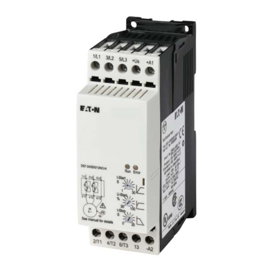
Eaton's DS7 solid-state soft start controller is an electronic, self-contained panel- or enclosuremounted motor soft-starting device. It provides three-phase induction motors with a smooth start, both mechanically and electrically. The DS7 line uses four silicon-controlled rectifiers (SCRs) that are connected in a full wave-power bridge on two phases. The voltage and current applied to the motor are controlled by varying the SCR conduction period. This, in turn, controls the torque developed by the motor. After the motor reaches speed, a bypass relay is energized to bypass the SCRs. The DS7 is designed to fulfill the industrial service requirements of applications such as chiller starters, pump panels, and machine tools. This device meets all relevant specifications set forth by UL 508, IEC 60947-4-2, CE, C-Tick, and CSA.
This leaflet covers basic installation and setup. No publication can take into account every possible situation. If you require further assistance with any aspect of this product or a particular application, contact Eaton.
Inspection
General
Upon receipt of the unit, verify that the catalog number and unit options stated on the shipping container match those stated on the order/ purchase form.
Inspect the equipment upon delivery. Report any carton damage to the carrier prior to accepting the delivery. Have this information noted on the freight bill. Eaton is not responsible for damage incurred in shipping.
Unpacking
Remove all packing material from the unit. Be sure to remove all packing material from the lug location.
Check the unit for any signs of shipping damage. If damage to the product is found after unpacking, report it to the freight company. Retain the packing materials for the carrier to review.
Verify that the unit's catalog number and options match those stated on the order/purchase form.
Storage
It is recommended that the unit be stored in its original shipping box/crate until it is to be installed.
The unit should be stored in a location where:
- The ambient temperature is between –13° to 140°F (–25° to 55°C)
- The relative humidity is between 0% and 95%, noncondensing
- The environment is dry, clean, and noncorrosive
- The unit will not be subjected to high shock or vibration conditions
Mounting instructions
The DS7 solid-state soft start controller is easy to mount. It does not require any special tools. To aid you with panel layout, refer to the dimension drawings shown in Figure 1. Drill and tap holes per mounting hole/slot locations as shown. To mount the unit, use all the hardware specified in Table 1 of this leaflet. Tighten to the specified torque.
Figure 1. 4 to 12 ampere models


HIGH VOLTAGE
HAZARDOUS VOLTAGE CAN CAUSE ELECTRIC SHOCK AND BURNS. TO AVOID SHOCK HAZARD, DISCONNECT ALL POWER TO THE CONTROLLER, MOTOR, OR OTHER CONTROL DEVICES BEFORE ANY WORK IS PERFORMED ON THIS EQUIPMENT. FAILURE TO DO SO WILL RESULT IN PERSONAL INJURY, DEATH, OR SUBSTANTIAL PROPERTY DAMAGE.
DO NOT APPLY A DISCONNECT DEVICE ON THE OUTPUT OF THE DS7 SOFT START CONTROLLER UNLESS A MEANS TO TURN OFF THE DEVICE WHEN DISCONNECT SWITCH IS OPEN IS UTILIZED. OPENING THE DISCONNECT WHILE THE SOFT START CONTROLLER IS OPERATING MAY CAUSE A MALFUNCTION. CLOSING THE DISCONNECT SWITCH WHILE THE SOFT START CONTROLLER IS OPERATING WILL RESULT IN POTENTIAL EQUIPMENT DAMAGE AND PERSONNEL HAZARD.
Table 1. Mounting hardware and torque specifications
| Screw Size + Flat and Lock Washer | Quantity | Torque Requirements | Unit Weight Lbs (kg) |
| M4 | 4 | 10 lb-in (1.2 Nm) | 0.8 (0.35) |
Table 2. Environmental requirements
| Description | Requirement |
| Operating temperature | 32° to 104°F (0° to 40°C) up to 140°F (60°C) with derating of 1% of rated current per Kelvin |
| Storage temperature | 13° to 140°F (–25° to 60°C ) |
| Elevation | Up to 1000m; up to 2000m with derating of 1% rated current for each 100m |
| Humidity | Functional to 95% noncondensing |
| Operating orientation | Less than 30 degrees from horizontal |
| Minimum clearance— Upper and lower | 2.165 in (55 mm) to a wall, 0.984 in (25 mm) to an upper and lower NZM1 (size 1), 1.378 in (35 mm) to an NZM2 (size 2), consult documentation of the breaker used (ionization emissions) |
| Minimum clearance—sides | 0.0 in (0 mm) |
| Minimum clearance—face | 0.198 in (5 mm) |
| Shock resistance | 8g for 11 ms in any direction |
| Vibration resistance | 2M2 EN 60721-3-2: 10g (3.5 mm amplitude, 9 to 200 Hz) |
| Environment | Suitable for installation in a pollution Degree 2 environment |
| Emissions | The device is suitable for use in industrial environments in accordance with EN 55011/22 Class A |
Power wiring
Using the wiring diagram in Figure 2 and Table 3 as guides, connect the line and motor wiring in accordance with appropriate local and national codes.
Note: To provide optimum motor protection, the line and motor power wiring should be tightly bundled and run perpendicular to the orientation of the DS7. Soft start controller to motor cable length is not to exceed 325 ft (100m).
Figure 2. Power wiring diagram

Table 3. Power wire sizing and torque requirements
| Wire Size | Torque | Wire Strip Length |
| 18–10 AWG | 10.62 lb-in | 10 mm |
| 2 x 21–20 AWG | 10.62 lb-in | 10 mm |
HAZARDOUS VOLTAGE. WILL CAUSE DEATH OR SERIOUS INJURY.
HAZARDOUS VOLTAGE IS PRESENT IN THE OFF/STOP STATUS OF THE SOFT START CONTROLLER WHEN THE LINE VOLTAGE IS ENERGIZED.
Product selection—horsepower ratings
Please refer to Application Note AP03901006E for additional information on proper size selection.
Table 4. 10 second ramp, one start per hour, 300% current limit at 40°C

Table 5. 10 second ramp, one start per hour, 400% current limit at 40°C

Product selection—kW ratings according to IEC 60947-4-2
Please refer to Application Note AP03901006E for additional information on proper size selection.
Table 6. 10 second ramp, one start per hour, 300% current limit at 40°C

Table 7. 10 second ramp, one start per hour, 400% current limit at 40°C

Notes
- Actual motor FLAs vary. Verify these devices cover the motor specific FLA.
- Selections are based on motor FLA value at 480V.
- Not to be used with 230V.
- 24 Vac/Vdc device.
- 120/230 Vac device.
Control wiring
A minimum of 18 AWG should be used between the control power source and the soft start controller terminals.
Terminal connections are to be secured to a torque value of 10.62 lb-in.
Control wiring is connected to the DS7 soft start controller on the front of the unit. Use the wiring diagrams in Figure 3, Figure 4, and the sizing/torque information in Table 9 as guides
Figure 3. Direct start control wiring without soft stop

Figure 4. Direct start control wiring with soft stop

Figure 5. Start and stop ramp functions

Table 8. Terminal designations
| Terminal | Description |
| –U s | Control ground or circuit common |
| +U s | Power of AC load |
| –A2 | Common with –U s |
| +A1 | Run command |
| 13 | Top of ramp contacts—NO |
Table 9. DS7 terminal control block wiring
| Name | Block Designation | Input | Connections |
| Circuit common | –U s | Common | Control ground or circuit common |
| Power | +U s | 24 Vac/Vdc/120–230 Vac maintained | Plus DC power or AC load |
| –A2 | –A2 | Control power common | Common with –U s |
| +A1 | +A1 | 24 Vac/Vdc/120–230 Vac maintained | Run command |
| Relay | 13 | NO contact rated at 250 Vac, 3A resistive, 1A inductive | Top of ramp signal— in bypass |
Control power requirements
The AC control power for your DS7 soft start controller must meet or exceed the following requirements:
- Minimum supply current:
- 20 mA
- 30 mA (with optional fan)
- 100 mA (with optional fan, in bypass)
- Peak current requirement = 250 mA for 50 ms
Operations
- 24 Vac/Vdc, 110/230 Vac control voltage is applied to terminal Us
- Line voltage is applied to the starter by closing the mains contactor
- The soft start controller issues a RUN command by applying 24 Vac/Vdc, 110/230 Vac to terminal +A1. Contacts 13 and –A2 will close when the end of the ramp time is reached (TOR)
Note: Bypass relays close at the end of ramp time + ~0.18 seconds. It is important to correctly set the ramp time, so the bypass relays will close within 5 seconds after the motor has achieved rated RPM.
- To remove the RUN command, remove control voltage from terminal +A1
- If ramp STOP time is set to a value greater than 0 seconds, a RAMP STOP will be performed
Adjusting the soft start controller parameters
There are three adjustments to the DS7 soft start controller:
- t-Start = ramp time
- u-Start = initial voltage (torque)
- t-Stop = stop ramp time
Table 10. DS7 parameters
| Application | t-Start | t-Stop | u-Start | Breakaway Torque | Remarks |
| Crusher, empty at start | 20s | — | 56% | 75% | Possible high inertia |
| Conveyor, horizontal, loaded | 25s | 30s | 76% | 150% | — |
| Conveyor, horizontal, unloaded | 25s | 30s | 48% | 50% | — |
| Chiller | 5s | — | 37% | 25% | — |
| Piston compressor, unloaded | 10s | — | 64% | 100% | — |
| Circular saw | 20s | — | 48% | 50% | Possible high inertia |
| Ball mill | 20s | — | 48% | 50% | Eccentric load |
| Mixer, liquids | 10s | — | 37% | 40% | — |
| Mixer, dry materials | 15s | — | 56% | 75% | — |
| Pump, piston | 25s | 30s | 82% | 175% | Possible high starting torque |
| Pump, centrifugal | 10s | 30s | 37% | 25% | — |
| Escalator | 10s | — | 48% | 50% | — |
| Rotary compressor, unloaded | 20s | — | 42% | 35% | — |
| Agitator | 15s | — | 42% | 35% | — |
| Feed screw | 20s | — | 82% | 175% | Possible high starting torque |
| Press, flywheel | 25s | — | 76% | 150% | Possible high starting torque |
| Drier, rotating | 20s | — | 64% | 100% | — |
| Blower, axial fan, flaps open | 30s | — | 37% | 25% | — |
| Blower, centrifugal fan, valve open | 30s | — | 35% | 20% | — |
LED operation and troubleshooting
The operation, warning, and fault status of the controller may be determined by observing the pattern of LED illuminations. Only one condition may exist at any one time, with fault indications taking priority over others.
As conditions change, LED status will also change.
For example, during the initialization stage, the RED and GREEN LED's will flash alternately. When initialization is complete and the Enable signal is present, the GREEN LED will then flash one time per second and the RED LED will be off.
Table 11. LED operations/warning indications

In the event of a motor stop due to a trip condition by the soft start controller, the FAULT status LED will be illuminated (flashing). In this case, one or more conditions found in Table 12 may have occurred.
Tables 13, 14 and 15 may be used for evaluation or troubleshooting and contain additional information on operations and operating conditions.
Table 12. LED fault indications

Table 13. Normal operation indications

Table 14. Warning indications
| Status | LED | Condition | Action |
| Start without enable | GREEN—1x/s, pulse 1/2s RED—1x/s, pulse 1/2s simultaneous | RUN command is issued without a signal at the Enable terminal. | Apply Enable signal at terminal EN. |
| Note: Thermal memory calculation is based on previous run conditions, not current potentiometer settings. | |||
| Overtemperature for next start | GREEN—1x/s, pulse 1/2s RED—1x/s, pulse 1/2s alternating | Thermal memory too high to attempt a start. | Delay RUN command. Reduce number of starts per hour. Increase frame size of soft start controller |
| Note: Thermal memory if the soft start controller calculates that the SCRs will be subject to overtemperature conditions during another start attempt. Thermal memory calculation is based on previous run conditions, not current potentiometer settings. | |||
| Potentiometer not effective, network operation | GREEN 1x/s, pulse 1/2s + 1x/s, pulse 1/8s RED—Off | RUN parameter potentiometers cannot be adjusted. | The soft start controller is connected to a control network. |
| Note: The values of the potentiometers on the face of the controller are not recognized when the soft start controller is connected to a network. | |||
Table 15. Fault indications
| Status | LED | Condition | Action |
| Overtemperature, SCR (I2t) | GREEN – 2x/s, pulse 1/8s RED—1x/s, pulse 1/2s simultaneous | Operating temperature of an SCR has been exceeded. | Allow controller to cool. Reduce operating load. |
| Note: Provide additional cooling to the enclosure if this fault is consistent with normal operation. Also consider increasing to a larger size soft start controller with a higher current rating. | |||
| Overtemperature, electronic | GREEN—Continuous RED—1x/s, pulse 1/2s | Temperature of the printed circuit board has been exceeded. | Reduce operating temperature of the controller. Install cooling fans. |
| Note: Additional cooling may be provided with optional fans to reduce temperature inside the enclosure. If not mounted inside an enclosure, move the controller to an optimum location to reduce operating temperatures. | |||
| Over/under temperature, heat sink | GREEN—Continuous RED—Continuous | Temperature of the SCR heat sink is not within operating specifications. | Reduce operating temperature. Increase operating temperature. |
| Note: Indication is the same for either high or low temperature. Note operating temperature of the environment. An infrared temperature device may be used on the face of the soft start controller to determine if the fault condition is either high or low temperature. | |||
| Thyristor defective | GREEN—Off RED—Continuous | SCR is shorted. SCR is open. | Inspect controller for shorted SCR. Inspect controller for open SCR. |
| Note: In troubleshooting this condition, please note that one phase is a pass through connection and will indicate very low resistance when measured with test equipment. A shorted SCR will also indicate a very low resistance. Prior to replacing the soft start controller, verify that the respective bypass relay is not stuck or welded in the closed position. Normal; thyristor resistance is greater than 10k ohms, measured from line to load with all external devices disconnected from the controller. | |||
| Phase failure | GREEN—Off RED—1x/s, pulse 1/2s | One or more of the line phases is missing. | Restore missing phases. Close isolation contactors if installed. |
| Note: Phase failure is not detected on the pass thru phase. | |||
| Bypass defective | GREEN—1x/s, pulse 1/2s RED—Off | Bypass relay closed prior to RUN command after initialization is complete. Bypass relay fails to close at the end of ramp time. | Inspect phases for evidence of closed bypass relay. Inspect phases for evidence of failed relay (voltage drop). |
| Note: Verify that the relay operates properly when TOR is achieved. Verify that the relay contacts are open when the controller has completed the initialization period. | |||
| Supply voltage faulty | GREEN—4x/s, pulse 1/8s RED—1x/s, pulse 1/2s simultaneous | Control power voltage is not within operating specifications (high or low). | Verify correct voltage. Correct excessive voltage drop condition. Verify the CPT is sized correctly and output voltage is correct. |
| Note: Inspect supply voltage for proper level and stability. Verify that CPT is of sufficient capacity and that it is operating properly. | |||
Service
For additional information on this product, please call Eaton's Technical Resource Center at (877) 386-2273 or visit our Web site at www.eaton.com.
Service and repair is available from Eaton or several factory authorized regional service centers. Please contact Eaton's Product Integrity Center at (800) 345-0434 for the location nearest to you.
For field service or start-up assistance 24 hours a day, 7 days a week, please call (800) 498-2678.
Eaton Corporation
Electrical Sector 1111 Superior Ave.
Cleveland, OH 44114
United States
877-ETN-CARE (877-386-2273)
Eaton.com
Documents / ResourcesDownload manual
Here you can download full pdf version of manual, it may contain additional safety instructions, warranty information, FCC rules, etc.
Download Eaton DS7 Series, DS7-342SX004N0-N, DS7-340SX004N0-N Manual
Advertisement


Need help?
Do you have a question about the DS7 Series and is the answer not in the manual?
Questions and answers