Keysight n9020a Service Manual
Mxa signal analyzer
Hide thumbs
Also See for n9020a:
- Measurement manual (225 pages) ,
- Manual (119 pages) ,
- Security features and document of volatility (77 pages)
Table of Contents
Advertisement
Quick Links
Download this manual
See also:
Manual
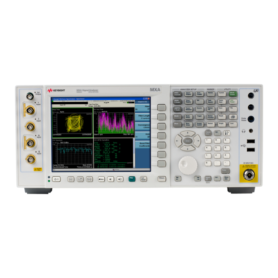
Keysight X-Series Signal Analyzers
N9020A MXA Signal Analyzer
This manual provides documentation for the following Analyzers:
N9020A Option 503 (20 Hz – 3.6 GHz)
N9020A Option 508 (20 Hz – 8.4 GHz)
N9020A Option 513 (20 Hz – 13.6 GHz)
N9020A Option 526 (20 Hz – 26.5 GHz)
Notice: This document contains references to Agilent.
Please note that Agilent's Test and Measurement
business has become Keysight Technologies. For
more information, go to www.keysight.com.
Service Guide
Advertisement
Table of Contents
Troubleshooting

Related Manuals for Keysight n9020a


Summary of Contents for Keysight n9020a
- Page 1 Keysight X-Series Signal Analyzers N9020A MXA Signal Analyzer This manual provides documentation for the following Analyzers: N9020A Option 503 (20 Hz – 3.6 GHz) N9020A Option 508 (20 Hz – 8.4 GHz) N9020A Option 513 (20 Hz – 13.6 GHz) N9020A Option 526 (20 Hz –...
-
Page 2: Safety Notices
DOCUMENT OR ANY INFORMATION A WARNING notice denotes a hazard. CONTAINED HEREIN. SHOULD It calls attention to an operating KEYSIGHT AND THE USER HAVE A procedure, practice, or the like that, SEPARATE WRITTEN AGREEMENT if not correctly performed or adhered... - Page 3 To receive the latest updates by email, subscribe to Keysight Email Updates at the following URL: http://www.keysight.com/find/MyKeysight Information on preventing analyzer damage can be found at: www.keysight.com/find/PreventingInstrumentRepair Is your product software up-to-date? Periodically, Keysight releases software updates to fix known defects and incorporate product enhancements. To search for software updates for your product, go to the Keysight Technical Support website at: http://www.keysight.com/find/techsupport...
-
Page 5: Table Of Contents
Keysight MXA Signal Analyzer Overview ........ - Page 6 Contents Fan(s) Are Not Operating ..............55 No Agilent Splash Screen Displayed .
- Page 7 Contents What You Will Find in This Chapter ............. 137 RF Section Description .
- Page 8 Contents A3 Digital IF Troubleshooting ............. . 265 ≥...
- Page 9 Contents (Cover On) ................. 322 A7 Midplane Description .
- Page 10 Contents LO Band Lock ................357 LO Control .
- Page 11 Contents without Option B85, B1A, or B1X) ............487 Removal (Serial Prefix ≥...
- Page 12 Contents 16. Functional Tests Functional Test Versus Performance Verification ..............599 Before Performing a Functional Test .
-
Page 13: Overview
What You Will Find in This Chapter This chapter provides overview information on your spectrum analyzer. The following sections are found in this chapter: Keysight MXA Signal Analyzer Overview on page 14 Instrument Option Descriptions on page 15 Signal Analyzer Accessories on page 16... -
Page 14: Keysight Mxa Signal Analyzer Overview
If customer requirements should change or expand, post sale upgrades can be purchased at any time. Many upgrades require a license key, which is obtained using the Keysight licensing process. If the Keysight Delivery Option is ordered, the entitlement certificate will be emailed to the customer the same day and the license key can be generated and installed in the MXA Signal Analyzer within minutes. -
Page 15: Instrument Option Descriptions
In order to find out all the requirements about installing an upgrade into the analyzer, refer to http://www.keysight.com/find/mxa_upgrades Description information of Option BBA, Analog Baseband IQ Inputs can be found on page 333. -
Page 16: Signal Analyzer Accessories
Signal Analyzer Accessories Signal Analyzer Accessories A number of accessories are available from Keysight Technologies to help you configure your analyzer for your specific applications. They can be ordered through your local Keysight Sales and Service Office and are listed below. -
Page 17: 50 Ohm Load
909D: DC to 26.5 GHz 50 Ohm/75 Ohm Minimum Loss Pad The Keysight 11852B is a low VSWR minimum loss pad that allows you to make measurements on 75 Ohm devices using an analyzer with a 50 Ohm input. It is effective over a frequency range of dc to 2 GHz. -
Page 18: Rf And Transient Limiters
Overview Signal Analyzer Accessories — The Keysight 85905A CATV 75 ohm preamplifier provides a minimum of 18 dB gain from 45 MHz to 1 GHz. (Power is supplied by the probe power output of the analyzer.) — The 11909A low noise preamplifier provides a minimum of 32 dB gain from 9 kHz to 1 GHz and a typical noise figure of 1.8 dB. -
Page 19: Before You Start Troubleshooting
Overview Before You Start Troubleshooting Before You Start Troubleshooting Before troubleshooting, complete the following tasks: — Familiarize yourself with the safety symbols marked on the instrument and read the general safety considerations in the front of this guide. — Read the ESD information below. —... - Page 20 Overview Before You Start Troubleshooting Any interruption of the protective conductor inside or outside of the product is likely to make the product dangerous. Intentional interruption is prohibited. Always use the three-prong ac power cord supplied with this product. Failure CAUTION to ensure adequate earth grounding by not using this cord may cause product damage.
-
Page 21: Esd Information
Overview ESD Information ESD Information Protection from Electrostatic Discharge Electrostatic discharge (ESD) can damage or destroy electronic components. All work on electronic assemblies should be performed at a static-safe workstation. Figure 1-1 shows an example of a static-safe workstation using two types of ESD protection: —... -
Page 22: Handling Of Electronic Components And Esd
Overview ESD Information Handling of Electronic Components and ESD The possibility of unseen damage caused by ESD is present whenever components are transported, stored, or used. The risk of ESD damage can be greatly reduced by paying close attention to how all components are handled. —... -
Page 23: Service Equipment You Will Need
— Front End Controller Troubleshooting Kit — USB Keyboard and Mouse — USB Storage Device — Test Equipment Calibration Application Software Information regarding the Keysight X-Series Signal Analyzer Calibration Application Software can be found at the following web site: www.keysight.com/find/calibrationsoftware... -
Page 24: Front End Controller Troubleshooting Kit
The Front End Troubleshooting kit lower level items can be purchased individually or as a complete kit with instructions. The complete listing of kit components, descriptions, and part numbers can be found below. Keysight Part Keysight Part Number Notes Front End Troubleshooting kit N9020-60005... -
Page 25: Usb Keyboard And Mouse
Most any size of storage device can be used, as the size of the file to be backed up is not much larger than a few megabytes. An optional 512 MB device can be ordered along with an instrument as N9020A-EFM, as an upgrade as N9020AK-EFM, or by using the part number 1819-0195. -
Page 26: Required Test Equipment List
Only the recommended and alternate equipment is compatible with the performance verification testing. Some tests can use various models of a particular equipment type. The “Recommended Keysight Model” is the preferred equipment. However, the “Alternative Keysight Model” is an acceptable substitute. - Page 27 Overview Service Equipment You Will Need Table 1-1 Required Test Equipment Instrument Critical Specifications Recommended Al ternative Model Model Ultra Low Noise Phase Noise (dBc/Hz) for 1 GHz tone and these Wenzel P, T Reference Frequency offsets: Associates Inc. Source 100 Hz −104 dBc/Hz Ultra Low Noise (required for testing PXA...
- Page 28 Overview Service Equipment You Will Need Table 1-1 Required Test Equipment Instrument Critical Specifications Recommended Al ternative Model Model Power Meter Dual Channel N1914A E4419A/B A, P Instrumentation Accuracy: ± 0.5% N1912A Power Reference Accuracy: ± 0.6% Compatible with 8480 series power sensors dB relative mode RF Power Sensor Frequency Range: 100 kHz to 3.6 GHz...
- Page 29 Instrument Critical Specifications Recommended Al ternative Model Model Standards Frequency Standard Frequency: 10 MHz Symmetricom Keysight 5061B, A, P 5071A 5071A −10 Accuracy: < ±1 e10 50 MHz, Frequency Drift: < 2.5 kHz Z5602A −25 dBm Calibrator Typical VSWR: 1.06:1 Opt H51 Output Power Variation: ±.004 dB...
- Page 30 Overview Service Equipment You Will Need Table 1-1 Required Test Equipment Instrument Critical Specifications Recommended Al ternative Model Model 10 dB Frequency: 50 MHz to 19.5 GHz 8493C A, P Fixed Attenuator Loss: 10 dB (nominal) (Option 010) VSWR: 321.4 MHz to 8 GHz: ≤ 1.1:1 8 GHz to 12.4 GHz: ≤...
- Page 31 Overview Service Equipment You Will Need Table 1-1 Required Test Equipment Instrument Critical Specifications Recommended Al ternative Model Model Directional Bridge Frequency Range: 50 MHz to 3 GHz 86205A Directivity: 50 MHz to 2 GHz:40 dB 2 GHz to 3 GHz: 30 dB VSWR: ≤...
- Page 32 Overview Service Equipment You Will Need Table 1-1 Required Test Equipment Instrument Critical Specifications Recommended Al ternative Model Model Filters 50 MHz Low Pass Cutoff Frequency: 50 MHz Telonic Berkeley 0955-0306 Rejection at 65 MHz: > 40 dB TLA 50-5AB2 Rejection at 75 MHz: >...
- Page 33 Shipped with the 8485A for adapting to the 08485-60005 A, P Power Reference. Only to be used for power sensor cal. Type-N Tee 1250-0559 Optional Equipment 10 MHz Distribution Symmetricom Keysight 5087A A, P Amplifier 5087B (only needed when using the 10 MHz Distribution Amplifier Setup)
- Page 34 Test uncertainty analysis. Lower cal factor uncertainties will translate to wider test margins. f. When ordering a new STD or CFT Power Sensor from Keysight to be used with the N7800A series applications, order with Option 1A7. The 1A7 option provides an ISO17025 calibration and includes calibration data.
- Page 35 Overview Service Equipment You Will Need h. 8491A Option H33 is a fixed attenuator which has been characterized to have a VSWR ≤ 1.05:1 at 50 MHz. A VSWR of 1.05:1 is recommended to test Input Attenuator Switching Uncertainty, Display Scale Fidelity, and Absolute Amplitude Accuracy performance tests.
- Page 36 Overview Service Equipment You Will Need Step Attenuator Loss Characterization The step attenuator combination should have each attenuator setting characterized by a metrology lab at 50 MHz. The following tables show which sections of the 10 dB and 1 dB step attenuators are utilized for each attenuator setting.
- Page 37 Overview Service Equipment You Will Need Table 1-3 10 dB Step Attenuator Nominal Attenuation Attenuator Section Allowable Uncertainty (dB) (dB) (10 dB) (20 dB) (40 dB) (40 dB) < 0.035 < 0.040 a. TME requires that Section 3 be characterized.
-
Page 38: After An Instrument Repair
After an Instrument Repair If any instrument assemblies have been repaired or replaced, perform the related adjustments and performance verification tests. These tests are done using the N7814A Keysight X-Series Signal Analyzer Calibration Application Software. Refer to Chapter 15, “Post-Repair Procedures”... -
Page 39: Contacting Keysight Technologies
Keysight office listed in Table 1-4. In any correspondence or telephone conversations, refer to the instrument by its model number (N9020A) and full serial number (ex. MY49250887). With this information, the Keysight representative can quickly determine whether your unit is still within its warranty period. - Page 40 Overview Contacting Keysight Technologies Table 1-4 Contacting Keysight Online assistance: www.keysight.com/find/contactus Americas Country Phone Number Canada (877) 894 4414 Brazil 55 11 3351 7010 Mexico 001 800 254 2440 United States 1 800 829-4444 Asia Pacific Country Phone Number Australia...
- Page 41 Overview Contacting Keysight Technologies Europe and Middle Country Phone Number Luxembourg +32 800 58580 Netherlands 0800 0233200 Russia 8800 5009286 Spain 0800 000154 Swedan 0200 882255 Switzerland 0800 805353 Opt. 1 (DE) Opt. 2 (FR) Opt. 3 (IT) United Kingdom...
-
Page 42: Instrument Serial Numbers
Instrument Serial Numbers Keysight makes frequent improvements to its products enhancing performance, usability, or reliability. Keysight service personnel have access to complete records of design changes to each type of instrument, based on the instrument’s serial number and option designation. -
Page 43: How To Return Your Instrument For Service
How to Return Your Instrument for Service How to Return Your Instrument for Service Service Order Number If an instrument is being returned to Keysight for servicing, the phone numbers are mentioned in Table 1-4, “Contacting Keysight,” on page 40. In order for Keysight to expedite the repair please be as specific as possible about the nature of the failure. -
Page 44: Other Packaging
Overview How to Return Your Instrument for Service Other Packaging Instrument damage can result from using packaging materials other than CAUTION those specified. Never use styrene pellets in any shape as packaging materials. They do not adequately cushion the equipment or prevent it from shifting in the carton. -
Page 45: Boot Up And Initialization Troubleshooting
Keysight X-Series Signal Analyzers N9020A MXA Signal Analyzer Service Guide Boot Up and Initialization Troubleshooting What You Will Find in This Chapter This chapter provides information that is useful when starting to troubleshoot a spectrum analyzer. It includes procedures for troubleshooting common failures and provides information on isolating problems in the analyzer. -
Page 46: Check The Basics
Boot Up and Initialization Troubleshooting Check the Basics Check the Basics Before calling Keysight Technologies or returning the instrument for service, please make the following checks: 1. Is there power at the power outlet? At the power receptacle on the instrument? 2. -
Page 47: Instrument Boot Up Process
Boot Up and Initialization Troubleshooting Instrument Boot Up Process Instrument Boot Up Process This section describes the signal analyzer boot up process from initial AC power to a normal analyzer sweep. The boot process time from start to finish will take 3 to 4 minutes. This boot time will vary slightly depending on the analyzer hardware configuration, installed options and the number of measurement applications. -
Page 48: Typical Instrument Boot-Up Process Flow
Boot Up and Initialization Troubleshooting Instrument Boot Up Process Typical instrument boot-up process flow 1. Plug in the AC power cord from a known good AC power source into the rear panel of the analyzer. 2. The yellow standby LED illuminates on the analyzer front panel to the left-hand side of the On/Off button. - Page 49 9. By default, the initialization process of the MXA Spectrum Analyzer application begins loading. The N9020A MXA Signal Analyzer screen appears. The screen remains for slightly over 1 minute. If any of the initializing processes do not complete, refer to the “Initializations Did Not...
- Page 50 Boot Up and Initialization Troubleshooting Instrument Boot Up Process 11.If any of the initial alignments fail, check the alignment history for troubleshooting hints. The instrument alignment history can be found at: E:\AlignDataStorage\AlignmentHistory.txt Look for any failed status for the various internal hardware items listed in this file.
-
Page 51: Potential Problems During Boot Process
Boot Up and Initialization Troubleshooting Potential Problems During Boot Process Potential Problems During Boot Process This section describes potential problems that may occur if there is an internal hardware issue that prohibits the MXA from completing a full boot up to the spectrum analyzer application. - Page 52 Boot Up and Initialization Troubleshooting Potential Problems During Boot Process All DC power supplies come from the A6 Power Supply assembly. However, NOTE the most convenient measurement location for all the DC supplies is the A7 Midplane. All power supply LED's are accessible once the instrument cover has been removed.
-
Page 53: Green Power On Led Does Not Illuminate
Boot Up and Initialization Troubleshooting Potential Problems During Boot Process Green Power On LED Does Not Illuminate Control of the green front panel Power On LED comes from the A4 CPU board assembly. This signal is routed through the A7 Midplane board and is then buffered on the A8 Motherboard before being sent to the A1A2 Front Panel Interface board through W1. - Page 54 Boot Up and Initialization Troubleshooting Potential Problems During Boot Process Figure 2-4 A7 Midplane Board - R867 5. While monitoring the voltage at R867, turn the instrument power on by pressing the front panel On/Off button. Does the voltage at R867 measure 0 VDC? If yes: Proceed to step...
-
Page 55: Fan(S) Are Not Operating
Boot Up and Initialization Troubleshooting Potential Problems During Boot Process Fan(s) Are Not Operating Control of the instrument fans comes from the A6 Power Supply assembly. This signal is routed from the A6 Power Supply through the A7 Midplane board, where there is a test point and LED to monitor the level, and is then routed to the A8 Motherboard where it is filtered before being sent to the Fans. - Page 56 Boot Up and Initialization Troubleshooting Potential Problems During Boot Process Before replacing the power supply, verify the midplane and motherboard NOTE interconnects are mechanically secure. Figure 2-5 A7 Midplane Board - Fan LED 6. With the instrument turned off, and the AC power cord removed, remove the Fan Assembly including unplugging both fans from the A8 Motherboard.
-
Page 57: No Agilent Splash Screen Displayed
Boot Up and Initialization Troubleshooting Potential Problems During Boot Process No Agilent Splash Screen Displayed (Black background with white “Agilent Technologies” text) A problem of not displaying the Agilent splash screen could be caused by many different things. It could be due to a down power supply, a processor hardware problem, an instrument boot-up process error, a display section failure, etc. -
Page 58: Instrument Hangs At The Agilent Splash Screen
Boot Up and Initialization Troubleshooting Potential Problems During Boot Process Instrument Hangs at the Agilent Splash Screen A problem of the instrument hanging at the Agilent splash screen could be caused by many different things. It could be due to a down power supply, a processor hardware problem, an instrument boot-up process error, etc. -
Page 59: Instrument Cannot Completely Load Or Run The Operating System
Boot Up and Initialization Troubleshooting Potential Problems During Boot Process Instrument Cannot Completely Load or Run the Operating System A problem of the instrument not loading the operating system can be caused by a few different things. It could be due to a down power supply, a processor hardware problem, an instrument boot-up process error, corrupt hard drive, etc. -
Page 60: Verify Lcd Backlight Functionality
Boot Up and Initialization Troubleshooting Potential Problems During Boot Process Verify LCD Backlight Functionality There are two backlights within the LCD assembly, one across the top and one across the bottom. If only one of the backlights has burnt out, the other will still function. - Page 61 Boot Up and Initialization Troubleshooting Potential Problems During Boot Process 6. Refer to Figure 2-6, verify that the +12D VDC power supply is on. Figure 2-6 A7 Midplane Board +12D LED Is the +12D backlight supply voltage LED on? If yes: Proceed to step If no:...
- Page 62 Boot Up and Initialization Troubleshooting Potential Problems During Boot Process Figure 2-7 A1A2 Front Panel Interface Board LCD Backlight Inverter Control Voltages Table 2-1 Expected Backlight Inverter Control Voltage Levels Signal Expected Vol tage Brightness Control 0 to 3 VDC Inverter Enable >6 VDC Inverter Supply...
-
Page 63: Verify Video Signal Path Integrity
Boot Up and Initialization Troubleshooting Potential Problems During Boot Process 10.Are all of the 3 voltage levels within their expected ranges? If yes: Replace the A1A4 LCD Inverter or DC-DC Converter board. If no: Replace the A1A2 Front Panel Interface board. Verify Video Signal Path Integrity The video controller is located on the A4 Processor assembly and is routed to the front panel LCD through a few interconnections. -
Page 64: Fails An Initial Alignment
Boot Up and Initialization Troubleshooting Potential Problems During Boot Process If there is a problem with any of these initializations not completing or causing an error message to be displayed refer to the instrument Event Log. This can be accessed by using an external USB keyboard and mouse and selecting Start, Run, enter Eventvwr.exe, and select OK. - Page 65 Boot Up and Initialization Troubleshooting Potential Problems During Boot Process Table 2-2 Initial Alignments Alignment Description Most Probable Related Hard ware Hard ware Failure AIF LC Wide Prefilter Passband Tuning A2 Analog IF Algorithm Adjusts the LC prefilter centering with the prefilter BW set to about 1.12 MHz.
- Page 66 Boot Up and Initialization Troubleshooting Potential Problems During Boot Process Table 2-2 Initial Alignments Alignment Description Most Probable Related Hard ware Hard ware Failure AIF Step Gain Algorithm A2 Analog IF Measures the relative gain of the IF for high gain (10 dB) versus the low gain (0 dB) paths.
- Page 67 Boot Up and Initialization Troubleshooting Potential Problems During Boot Process Table 2-2 Initial Alignments Alignment Description Most Probable Related Hard ware Hard ware Failure Narrow Band Step Cal Ad justment Alignment Alignment signal Algorithm originates on A3 D-IF, then goes through A16 Recalled adjustment from calibration file.
- Page 68 Boot Up and Initialization Troubleshooting Potential Problems During Boot Process Table 2-2 Initial Alignments Alignment Description Most Probable Related Hard ware Hard ware Failure Low Band Elec Atten Path System Gain A13 Front End 50 MHz calibrator on A16 Algorithm Reference.
- Page 69 Boot Up and Initialization Troubleshooting Potential Problems During Boot Process Table 2-2 Initial Alignments Alignment Description Most Probable Related Hard ware Hard ware Failure WBDIF Pulse Stretcher Alignment Algorithm A26 WBDIF (Option B85, B1A, or B1X) DC Offset Alignment Algorithm A19 BBIQ Main (Option BBA) A18 BBIQ Interface...
-
Page 70: Signal Level Verification
Boot Up and Initialization Troubleshooting Signal Level Verification Signal Level Verification Signal Level Problem with Input Frequencies < 3.6 GHz Measure the 50 MHz RF calibrator signal level by pressing Input/Output, RF Calibrator, 50 MHz. Now press Freq, 50 MHz, SPAN, 1 MHz, Peak Search. If the analyzer is functioning correctly in low band, the 50 MHz calibrator level should be −25 dBm ±... -
Page 71: Signal Level Problem With Input Frequencies > 3.6 Ghz
Boot Up and Initialization Troubleshooting Signal Level Verification Signal Level Problem with Input Frequencies > 3.6 GHz Measure the 4.8 GHz RF calibrator signal level by pressing Input/Output, {RF Calibrator}, 4.8 GHz. Now press Freq, 4.8 GHz, SPAN, 1 MHz, Peak Search. If the analyzer is functioning correctly in high band, the 4.8 GHz calibrator level should be −28 dBm ±... - Page 72 Boot Up and Initialization Troubleshooting Signal Level Verification...
-
Page 73: Instrument Messages
Keysight X-Series Signal Analyzers N9020A MXA Signal Analyzer Service Guide Instrument Messages Introduction The Error and Status messaging system of the instrument reports events and conditions in a consistent fashion, as well as logging and reporting event history. Event vs. Condition Messages —... -
Page 74: Event And Condition Categories
Instrument Messages Introduction Event and Condition Categories The three categories of severity are described below, for both Events and Conditions. Errors Error messages appear when a requested operation has failed. (For example, “Detector not available”, “File not saved”.) Error messages are often generated during remote operation when an invalid programming command has been entered. -
Page 75: Event Message Format
Instrument Messages Introduction Ad visories Advisory messages tell the front panel user some useful information. (For example, “File saved successfully” or “Measuring the fundamental”.) Advisory messages appear in the Status Panel at the bottom of the display. The message remains until you press a key, or another message is displayed in its place. -
Page 76: Event Queues
Instrument Messages Introduction Figure 3-2 Error Message Example Event Queues There are several different event queues that are viewed/queried and managed separately. Note that Conditions are logged in the queues as pairs of events: a “Detected” event and a corresponding “Cleared” event. Table 3-1 Event Queue Types Front Panel Status... - Page 77 Instrument Messages Introduction Table 3-2 Characteristics of the Event Queues Characteristic Front-Panel Status Front-Panel History Remote Interfaces (GPIB/LAN) Circular (rotating). Circular (rotating). Linear, first-in/first-out. Overflow Handling Drops oldest error as new Drops oldest error as new Replaces newest error with: error comes in.
-
Page 78: Advisory Messages
Instrument Messages Advisory Messages Advisory Messages An advisory is simply a message that lets you know something useful; for example “File saved successfully” or “Measuring fundamental.” Operation completion and running status indications are common types of advisories. Advisories have no number and are not logged in the error queue. Advisories include gray-out “settings conflict”... - Page 79 Instrument Messages Advisory Messages Message Description/Correction Information When freq points being measured are above 3.6 GHz and a calibration has been Cal Invalid: meas freq successfully performed, and the number of points are changed, the new points are pt(s) > 3.6GHz are > required to be within 50 MHz of the current cal points or the preselector optimize 50MHz from existing Cal frequencies become inaccurate and the whole cal needs to be invalidated.
- Page 80 Instrument Messages Advisory Messages Message Description/Correction Information The demodulated burst type has not been found in the originally demodulated slot Frequency Hopping location within the frame enabled, waiting for valid burst The frequency context parameter has been changed either by the user or the Frequency menu has system.
- Page 81 <port> The Keysight Smart Noise Source has been connected and the application is Reading SNS data… reading the device EEPROM data. Please wait until complete before continuing A file recall (open/load) was successfully completed...
- Page 82 Instrument Messages Advisory Messages Message Description/Correction Information The Double Side Band measurement requires careful setup to obtain valid results. Refer to online help for Please refer to the manuals for help with this setup assistance with DSB measurements The selected timeslot is not on. (Timeslot is referenced to the trigger point) Requested timeslot number is not present.
- Page 83 Instrument Messages Advisory Messages Message Description/Correction Information Sync is RF Ampl (not Training Sequence). Bits are not accurate. The trace saving operation was successful Trace file saved. When in Gate View you use Gate View Sweep Time, rather than Sweep Time, to Use Gate View Sweep Time control the Gate View window in the Gate menu.
-
Page 84: Event Messages
Instrument Messages Event Messages Event Messages Event messages are displayed in the MSG area in the bottom left of the instrument display. Event messages and message numbers are defined by the SCPI standard. In the X-Series, sub-messages are often attached to add additional information, to help you better understand the event being reported. -
Page 85: 800, Operation Complete Event
Instrument Messages Event Messages –800, Operation Complete Event Err# Message Verbose/Correction Information –800 The instrument has completed all selected pending operations in accordance Operation complete with the IEEE 488.2, 12.5.2 synchronization protocol –700, Request Control Event Err# Message Verbose/Correction Information –700 The instrument requested to become the active IEEE 4881 Request control... -
Page 86: -300 To -399, Device-Specific Errors
Verbose/Correction Information –300 An instrument error occurred and the exact problem cannot be specifically Device-specific error identified. Report this error to the nearest Keysight Technologies sales or service office –310 An internal system-type error has occurred. The exact problem cannot be System error;... - Page 87 Instrument Messages Event Messages Err# Message Verbose/Correction Information –310 Signal source at given IP address is not responding / IP does not belong to a System Error; No source. Check IP address and network connection supported source found –310 Signal source at given IP address is not responding / IP does not belong to a System Error;...
- Page 88 There was a problem with instrument remote communications. The exact Communication error problem cannot be specifically identified –360 The Keysight Smart Noise Source connected to the instrument has failed to be Communication error; read by the application. Please disconnect and reconnect the SNS. If this SNS data read continues to fail, then the SNS may have had its EEPROM corrupted or another failure.
-
Page 89: -221 Settings Conflict Errors
Instrument Messages Event Messages –221 Settings Conflict Errors This is one of the errors in the standard SCPI error range –200 to –299. For all other errors in this range, see “–200 to –299, Execution Errors” on page 101. Err# Message Verbose/Correction Information –221... - Page 90 Instrument Messages Event Messages Err# Message Verbose/Correction Information –221 You must be in Tracking Source mode to use the Cal functions under Settings conflict; Normalize. Press Source, Source Mode and set it to Tracking Cal only available when Source Mode is Tracking –221 The cal ENR table has no values in it, and hence the cal cannot be performed.
- Page 91 Instrument Messages Event Messages Err# Message Verbose/Correction Information –221 The resulting trace data (from doing a trace math function) cannot be put into Settings conflict; the any of the traces that are being used by the math operation Destination trace for Trace Math cannot be a trace operand –221...
- Page 92 Instrument Messages Event Messages Err# Message Verbose/Correction Information –221 You have selected a feature that the selected source does not support Settings conflict; Feature not supported for selected source –221 Some functionality is not available when certain Inputs are selected. For Settings conflict;...
- Page 93 Instrument Messages Event Messages Err# Message Verbose/Correction Information –221 The electronic attenuator does not function above 3.6 GHz, so if you have Settings conflict; that attenuator enabled, you cannot change the center frequency so that Freq > 3.6 GHz frequencies above 3.6 GHz are displayed/measured unavailable while electronic attenuator enabled...
- Page 94 Instrument Messages Event Messages Err# Message Verbose/Correction Information –221 The Gate functions are unavailable when Source Mode is Tracking with an Settings conflict; external source. This is because the Gate circuitry is used to sync the external Gate not available source with external Tracking Source...
- Page 95 Instrument Messages Event Messages Err# Message Verbose/Correction Information –221 The marker count function cannot be used while you have gating turned on Settings conflict; Marker Count is not available when Gate –221 If a Marker is a Fixed type marker, the marker's value does not change from Settings conflict;...
- Page 96 Instrument Messages Event Messages Err# Message Verbose/Correction Information –221 These special units only apply when you are doing antenna measurements, Settings conflict; so you must have a correction that includes Antenna Units enabled Must apply Amplitude Correction to make this unit available –221 Optimize Preselector can only be performed on frequencies in high band, Settings conflict;...
- Page 97 Instrument Messages Event Messages Err# Message Verbose/Correction Information –221 SCPI only message. This parameter is only available when the Freq mode is Settings conflict; set to Swept. Change the Freq Mode to Swept Param only available when Frequency Mode is Swept –221 SCPI only message.
- Page 98 Instrument Messages Event Messages Err# Message Verbose/Correction Information –221 Signal Track is not available when you have selected Zero Span. So if Zero Settings conflict; Span is entered while in Signal Track is On, Signal Track is turned off Signal Track is turned off when Zero Span is selected –221...
- Page 99 Instrument Messages Event Messages Err# Message Verbose/Correction Information –221 This is an override that turns off many of the annotations. This is available as a Settings conflict; security feature System Display Settings, Annotation is Off –221 Meas Setup, ENR, Tcold The Tcold value set under needs to be lower Settings conflict;...
- Page 100 Instrument Messages Event Messages Err# Message Verbose/Correction Information –221 The Auto Scan Time/Meas Time are not available when Scan Type =Stepped Settings Scan conflict;Auto Scan Time/Meas Time do not apply in Stepped Scan Type. –221 The Auto Scan Time/Meas Time are not available when Scan Type =Stepped Settings Scan conflict;Auto Scan...
-
Page 101: -200 To -299, Execution Errors
Instrument Messages Event Messages Err# Message Verbose/Correction Information –221 Max of Total range points is 400000. Reduce Scan Points or increase Step Settings Size in order to turn on that range conflict;Range <0> is turned off as total range points > 40001 –221 If the frequency range is set above 1GHz, you cannot change to RF Input 2 Settings conflict;RF... - Page 102 Instrument Messages Event Messages Err# Message Verbose/Correction Information –200 Marker Zoom is not available as it has reached full zoom At Full Zoom –200 A program execution error has occurred. The exact problem cannot be Execution Error specifically identified –200 The entered channel/carrier frequency is not within the range of your current Execution error;...
- Page 103 Instrument Messages Event Messages Err# Message Verbose/Correction Information –200 The trace file may have been created by another version of the Phase Noise Execution error; personality, which uses a different trace format that is incompatible with the Trace file created by version you are running.
- Page 104 Instrument Messages Event Messages Err# Message Verbose/Correction Information –214 The trigger source for the initiation of a measurement is set to GET, and the Trigger deadlock following measurement query was received. The measurement cannot be started until a GET is received, but the GET would cause an INTERRUPTED error –215 The arm source for the initiation of a measurement is set to GET and the...
- Page 105 Instrument Messages Event Messages Err# Message Verbose/Correction Information –224 The list parameters have a maximum allowed length. You are trying to set a Illegal parameter length longer than the maximum value; Exceeding the max list length –224 The gated FFT function is not available if you have selected the swept type of Illegal parameter sweep.
- Page 106 Instrument Messages Event Messages Err# Message Verbose/Correction Information –224 You tried to turn on a measurement that is not available in the current mode Illegal parameter value; Measurement not available –224 You cannot set AC coupling in this instrument Illegal parameter value;This instrument is always DC coupled –224...
- Page 107 Instrument Messages Event Messages Err# Message Verbose/Correction Information –233 A legal data element was found but could not be used because the version of Invalid version the data is incorrect. For example, state data changes as new instrument features are added, so old state files may not work in an instrument with a newer version of software –240 A legal program command or query could not be executed because of a...
- Page 108 Instrument Messages Event Messages Err# Message Verbose/Correction Information –250 The system cannot find the path specified Mass storage error; Directory not found –250 The load trace operation could not be completed, as the input file was not in Mass storage error; the expected format.
- Page 109 Instrument Messages Event Messages Err# Message Verbose/Correction Information –250 Attempt to recall a register with nothing in it Mass storage error; Register <number> empty –250 The process cannot access the file because it is being used by another process Mass storage error; Sharing violation –250 You must have a Spectrogram on the screen before you can save it.
- Page 110 Instrument Messages Event Messages Err# Message Verbose/Correction Information –260 An error was found with an expression type of data element. The exact problem Expression error cannot be specifically identified –261 An expression that has legal syntax could not be executed because of a math Math error in error.
- Page 111 Instrument Messages Event Messages Err# Message Verbose/Correction Information –292 Referenced name does not exist –293 Referenced name already exists –294 Indicates that the type or structure of a memory item is inadequate Incompatible type...
-
Page 112: -100 To -199, Command Errors
Instrument Messages Event Messages –100 to –199, Command Errors Err# Message Verbose/Correction Information –100 There is a problem with the command. The exact problem cannot be Command error specifically identified –101 An invalid character was found in part of the command Invalid character –102 An unrecognized command or data type was found, for example a string was... - Page 113 Instrument Messages Event Messages Err# Message Verbose/Correction Information –130 A problem was found in a suffix (units). The exact problem cannot be Suffix error specifically identified –131 There is a syntax problem with the suffix. You need to use the suffix (units) that Invalid suffix are allowed by this command –134...
-
Page 114: Error
Instrument Messages Event Messages Err# Message Verbose/Correction Information –183 Indicates that the program message unit sequence, sent with a *DDT or *DMC Invalid inside macro command, is syntactically invalid definition –184 Indicates that a command inside the macro definition had the wrong number or Macro parameter error type of parameters 0 Error... -
Page 115: Condition Messages
Instrument Messages Condition Messages Condition Messages Condition messages are displayed in the STATUS message area in the bottom right of the display. Condition messages are classified as either “Errors” or “Warnings.” In the tables in this section, an E in the Error or Warning column means that an error is displayed on the front panel and sent out to SCPI when this condition is detected. - Page 116 Instrument Messages Condition Messages Err# Bit in Message Error or More Information status Warning register unused unused unused unused unused unused unused unused unused Condition Errors 36 to 64, Calibration Needed or Failed This series of errors corresponds to the bits in the STATus:QUEStionable:CALibration register.
- Page 117 Instrument Messages Condition Messages Thus, the summary bits cannot be used to determine the current state of a lower level condition bit; only the state and history of the lower level event bits. This register is itself summarized as bit 8 of the STATus:QUEStionable register, as described in the section “Condition Errors 601 to 699, Error Summaries”...
- Page 118 Instrument Messages Condition Messages Condition Errors 65 to 92, Calibration Needed (Extended) This series of errors corresponds to the bits in the STATus:QUEStionable:CALibration:EXTended:NEEDed sub-register. The second column in the table below shows the corresponding bit in that register. An event with the error number shown in the table means the condition has been detected.
- Page 119 Instrument Messages Condition Messages Condition Errors 67 to 95, Calibration Failure (Extended) This series of errors corresponds to the bits in the STATus:QUEStionable:CALibration:EXTended:FAILure sub-register. The second column in the table shows the corresponding bit in that register. An event with the error number shown in the table means the condition has been detected.
-
Page 120: Condition Errors 101 To 199, Measurement Integrity
Instrument Messages Condition Messages Condition Errors 101 to 199, Measurement Integrity This series of errors corresponds to the bits in the STATus:QUEStionable:INTegrity register. The second column in the table shows the corresponding bit in that register. An event with the error number shown in the table means the condition has been detected. - Page 121 Instrument Messages Condition Messages Err# Bit in Message Error or More Information status Warning register The current measurement does not support I/Q No Result; Meas invalid input; switch to the RF or another input or with I/Q inputs select a different measurement unused status bit This bit is the summary bit for the...
- Page 122 Instrument Messages Condition Messages Err# Bit in Message Error or More Information status Warning register Meas Error Memory Error A shortage of free memory related to longer Memory Error;Shorten capture intervals has occurred. The capture interval measurement is aborted and all results return invalid values I/O Error No IP address entered for external source and...
-
Page 123: Condition Errors 201 To 299, Signal Integrity
Instrument Messages Condition Messages Err# Bit in Message Error or More Information status Warning register The user has manually set the Analog Output Settings Alert; Analog Out under the Input/Output menu to a setting that settings conflict conflicts with the current measurement. There will be no output on the Analog Out port until this conflict is resolved. - Page 124 Instrument Messages Condition Messages For example, error 207 indicates a Burst Not Found condition has been detected, error 1207 indicates that failure has been cleared. This register is summarized as bit 0 of the STATus:QUEStionable:INTegrity register, as described in the section “Condition Errors 101 to 199, Measurement Integrity”...
- Page 125 Instrument Messages Condition Messages Err# Bit in Message Error or More Information status Warning register The selected timeslot does not contain the expected Burst not burst. found;with selected Time Slot Timing Error The pilot burst used for time reference is not active. Timing Error:No time ref pilot burst...
- Page 126 Instrument Messages Condition Messages Err# Bit in Message Error or More Information status Warning register This error is normally generated because of one of the Demod Error following reasons: 1. There is no carrier signal. 2. Walsh channels other than the pilot are active.
-
Page 127: Condition Errors 301 To 399, Uncalibrated Integrity
Instrument Messages Condition Messages Err# Bit in Message Error or More Information status Warning register No sub-frame or only part of one sub-frame is detected. Demod Error;No full subframe found Multiplexed Data Demod Bits are not generated even Demod Error;Muxed though Data channel is selected, because all 16 data bits not found code channels are not active... - Page 128 Instrument Messages Condition Messages An event with the error number shown in the table means the condition has been detected. When the condition is cleared, an event with the error number plus 1000 is generated. These error numbers can be viewed in the Show Errors screen, along with the DETECTED and CLEARED indicators.
- Page 129 Instrument Messages Condition Messages Err# Bit in Message Error or More Information status Warning register The existing user cal has been invalidated for one User Cal; Cal of the following reasons: invalidated Frequency: Setting the frequency outside the current valid user cal set (for example: If the current sweep range is 2 to 3GHz, then setting the start frequency to 1.9 GHz will invalidate the current user cal.
- Page 130 Instrument Messages Condition Messages Err# Bit in Message Error or More Information status Warning register The measurement RBW has been changed since User Cal; Adjusted the last calibration (~CAL) for new RBW Calibration One or more calibration or measurement Calibration; ENR frequency points exceed the currently loaded Cal table extrapolated or Meas ENR Table frequency ranges.
-
Page 131: Condition Errors 401 To 499, Power
Instrument Messages Condition Messages Condition Errors 401 to 499, Power This series of errors corresponds to the bits in the STATus:QUEStionable:POWer register. The second column in the table shows the corresponding bit in that register. An event with the error number shown in the table means the condition has been detected. - Page 132 Instrument Messages Condition Messages An event with the error number shown in the table means the condition has been detected. When the condition is cleared, an event with the error number plus 1000 is generated. These error numbers can be viewed in the Show Errors screen, along with the DETECTED and CLEARED indicators.
-
Page 133: Condition Errors 601 To 699, Error Summaries
Instrument Messages Condition Messages Condition Errors 601 to 699, Error Summaries This series of errors corresponds to the bits in the STATus:QUEStionable register, read with a STATus:QUEStionable? event query or a STATus:QUEStionable:CONDition? query. The second column in the table shows the corresponding bit in the status register. -
Page 134: Condition Errors 701 To 799, Operation
Instrument Messages Condition Messages Err# Bit in Message Error or More Information status Warning register status bit This bit is the summary bit for the Integrity only STATus:QUEStionable:INTegrity sub-register. unused unused unused unused unused Condition Errors 701 to 799, Operation This series of errors corresponds to the bits in the STATus:OPERation register, which can be read with a STATus:OPERation? event query or a STATus:OPERation:CONDition? query. -
Page 135: Condition Errors 801 To 899, Temperature
Instrument Messages Condition Messages Err# Bit in Message Error or More Information status Warning register unused status bit Paused only status bit The “Source Sweeping” bit is used to indicate Source Sweeping only various conditions, depending on the Mode of operation: In the List Sequencer mode, it is used to indicate that the sequencer is running... - Page 136 Instrument Messages Condition Messages Err# Bit in Message Error or More Information status Warning register unused unused unused unused unused unused unused unused unused unused unused unused unused unused...
-
Page 137: Rf Section Troubleshooting
Keysight X-Series Signal Analyzers N9020A MXA Signal Analyzer Service Guide RF Section Troubleshooting What You Will Find in This Chapter The following information is found in this chapter: 1. Theory of operation of the RF section 2. Isolating the cause of an hardware problem by verifying the functionality of assemblies in the RF section signal path. -
Page 138: Rf Section Description
RF Section Description Purpose This section covers only those optional frequency ranges listed below for the N9020A, Signal Analyzer. — Option 503, 3.6 GHz Frequency Range — Option 508, 8.4 GHz Frequency Range — Option 513, 13.6 GHz Frequency Range —... - Page 139 RF Section Troubleshooting RF Section Description The RF section is comprised of the following major assemblies: — A9 Input Attenuator A — A10 Input Attenuator B — A11 Low Band Switch Assembly — A12 YTF Preselector — A14 L.O. Synthesizer Assembly —...
- Page 140 RF Section Troubleshooting RF Section Description 1. RF input frequencies < 3600 MHz route through the low band path. Refer Chapter 11, “Block Diagrams” for details. The RF input signal level can be optimized by either Input Attenuator A or Input Attenuator B.
- Page 141 RF Section Troubleshooting RF Section Description 3. RF input frequencies from 13.6 GHz to 26.5 GHz go through high band path #2. Refer to Chapter 11, “Block Diagrams” for details. This signal level can be optimized by either Input Attenuator A or Input Attenuator B.
-
Page 142: Rf Section Theory Of Operation
RF Section Troubleshooting RF Section Description RF Section Theory of Operation A9 Input Attenuator A This assembly has two 2 dB attenuator sections, a DC block and a cal signal input port. With the DC block switched in (AC coupled mode), the low end minimum frequency range increases from 20 Hz to 10 MHz due to capacitive effects. - Page 143 RF Section Troubleshooting RF Section Description A14 L.O. Synthesizer Assembly The L.O. Synthesizer Assembly provides the 1st L.O. power that is required for the A13 RF Front End Assembly. The 1st L.O. has a frequency range from 3.80 to 8.70 GHz. Harmonics of the 1st L.O. are used to down convert RF input signals up to 26.5 GHz.
- Page 144 RF Section Troubleshooting RF Section Description A13 RF Front End Assembly This assembly is a self-contained microcircuit that is repaired at the assembly level. See Figure 4-1. Figure 4-1 A13 RF Front End Assembly View from Front Panel (Option EXM only) This assembly contains the following circuits: —...
- Page 145 RF Section Troubleshooting RF Section Description — External Mixing Diplexer (units with Option EXM only) Table 4-3 A13 RF Front End Signals Signal Name Description From RF Input 20 Hz to 3.59 GHz RF Input A11J2, Low Band Switch A13J2 Microwave Input 3.6 GHz to 26.5 GHz YTF Output or SW1...
-
Page 146: Troubleshooting
RF Section Troubleshooting Troubleshooting Troubleshooting Quick Check to Verify the Low Band Signal Path The analyzer has an internal 50 MHz amplitude reference signal that is used to verify the low band path. Refer to Chapter 11, “Block Diagrams” for details. Equipment needed: Functioning Spectrum Analyzer Cables &... - Page 147 RF Section Troubleshooting Troubleshooting Disconnect the W15 or W36 cable from A13J7 on the RF Front End Assembly (1) 322.5 MHz output. See Figure 4-2. Figure 4-2 W15 or W36 Location...
- Page 148 RF Section Troubleshooting Troubleshooting Connect A13J7 output to a functioning spectrum analyzer and verify the 322.5 MHz intermediate frequency is measuring −28.5 ± 3 dB using the same analyzer settings as in Figure 4-3. Figure 4-3 322.5 MHz Intermediate Frequency If this power level is correct the RF assembly from the A9 50 MHz Reference signal input port to A13J7, 322.5 MHz I.F.
- Page 149 RF Section Troubleshooting Troubleshooting If this power level is incorrect, the following assemblies need to be verified in the order listed using the 50 MHz internal calibrator signal. Be sure the 50 MHz calibrator is turned on Input/Output, RF Calibrator, 50 MHz when verifying the performance.
- Page 150 RF Section Troubleshooting Troubleshooting Figure 4-4 Remove the Side Chassis...
-
Page 151: Troubleshooting A Low Band Problem
RF Section Troubleshooting Troubleshooting Troubleshooting a Low Band Problem 1. Reference Assembly Verification Remove cable W19 from A9 Input Attenuator A (1) and measure the 50 MHz calibrator signal on the cable end with a functioning Spectrum Analyzer. Refer Figure 4-5. - Page 152 RF Section Troubleshooting Troubleshooting If the Reference assembly calibrator is functioning properly the 50 MHz calibrator signal will measure 50 MHz at −25 dBm ± 3 dB. See Figure 4-6. If this level is incorrect, the Reference assembly is most likely defective. Reconnect W19 at A9 Input Attenuator A.
- Page 153 RF Section Troubleshooting Troubleshooting 2. L.O. Synthesizer Assembly Verification Press the following keys on the analyzer: FREQ (Channel), 1 GHz SPAN (X Scale) Zero Span Refer to Figure 4-7. Disconnect cable W4 at A14J740 of the L.O. Synthesizer Assembly (1). Figure 4-7 W4 and W6 Location...
- Page 154 RF Section Troubleshooting Troubleshooting Connect the functioning Spectrum Analyzer and appropriate high frequency cable and connector to A14J740. Adjust the functioning Spectrum Analyzer to measure a signal at 6122.5 MHz at +16 dBm ± 4 dB as seen in Figure 4-8.
- Page 155 RF Section Troubleshooting Troubleshooting If this power level is incorrect remove W6 at A14J200. Refer to Figure 4-7. Adjust the functioning spectrum analyzer to measure a signal at 4.800 GHz at +4.5 dBm ± 2 dB. See Figure 4-9. Figure 4-9 4.800 GHz Signal at A14J200 If this power level is incorrect, the most probable cause is the A16 Reference Assembly.
- Page 156 RF Section Troubleshooting Troubleshooting 3. Front End Control Assembly Verification Verifying the Front End Control Assembly requires the RF Front End Troubleshooting board E4410-60115 or kit number N9020-60005. The kit includes the troubleshooting board and associated interconnect cables. The troubleshooting board and cables will help verify the control logic from this assembly to Input Attenuator A, Input Attenuator B, Low Band Switch, YTF Preselector, (Optional) Low Band Preamplifier, (Optional) High Band Preamplifier, (Optional) Electronic Attenuator and the RF Front End Assembly.
- Page 157 RF Section Troubleshooting Troubleshooting Figure 4-10 RF Front End Troubleshooting Board Figure 4-11 RF Front End Troubleshooting Board...
- Page 158 RF Section Troubleshooting Troubleshooting — Turn the instrument on and allow it to complete its full boot up process to the signal analyzer application. — Turn Auto Align off by pressing System, Alignments, Auto Align, Off on the analyzer. Resistors on the board can get very hot. CAUTION —...
- Page 159 RF Section Troubleshooting Troubleshooting Figure 4-12 Front End Troubleshooting Board Attenuation LEDs...
- Page 160 RF Section Troubleshooting Troubleshooting When the input attenuation is changed from 0 dB to 2 dB, the 2 dB Step LED DS15 should illuminate. When the input attenuation is changed from 2 dB to 4 dB, DS15 and DS16 should be illuminated as per Table 4-4.
- Page 161 RF Section Troubleshooting Troubleshooting 5. Input Attenuator B Control Logic Verification Press AMPTD, Attenuation 6 dB and verify the 6 dB Step LED DS17 is illuminated. Enter the input attenuation settings found in Table 4-5 and verify the proper LED's illuminate on the Front End Troubleshooting board according Table 4-5.
- Page 162 RF Section Troubleshooting Troubleshooting 6. Low Band Switch Control Logic Verification Press Mode Preset on the analyzer. Press FREQ, 50 MHz, SPAN, 2 MHz on the analyzer. Connect the DVM positive lead to one of the In1A test points, and the negative lead to the bottom of R46 (blue resistor near the bottom) on the Front End Troubleshooting board.
- Page 163 RF Section Troubleshooting Troubleshooting 7. YTF Preselector Control Logic Verification (All except Option 503) In order to properly measure the preselector tune output from the A15 Front NOTE End Control Assembly, the following items are required: — E9637A Banana plug to BNC (f) adapter —...
- Page 164 RF Section Troubleshooting Troubleshooting In order to measure the control current correctly, press Single on the analyzer NOTE in between each measurement. If any of the preselector control currents do not match the levels shown in Table 4-9, the most probable causes are a misaligned YTF or the A15 Front End Control Assembly.
- Page 165 RF Section Troubleshooting Troubleshooting 8. Front End Assembly Control Logic Verification Since the RF Front End Troubleshooting board is connected, now is a good time to test out the remaining control circuits from the A15 Front End Control Assembly. Table 4-10 Front End Control Logic Test Point Description...
- Page 166 RF Section Troubleshooting Troubleshooting Table 4-10 Front End Control Logic Test Point Description Instrument Vol tage Tolerance Settings (VDC) (VDC) S14A Sets path to either band 1 & 2 mixer or band CF 5 GHz −9.83 ±0.5 3 & 4 mixer CF 20 GHz +9.83 S14B...
- Page 167 RF Section Troubleshooting Troubleshooting Input Attenuator A Power Level Verification Press Mode Preset, Input/Output, RF Calibrator, 50 MHz, AMPTD, Attenuation, 0 dB on the analyzer. Refer to Figure 4-13, remove cable W11 from A9 (1) Output. Measure the 50 MHz calibrator signal on the output of the attenuator using a functioning Spectrum Analyzer.
- Page 168 RF Section Troubleshooting Troubleshooting The level should be −25 dBm ± 2 dB as shown in Figure 4-14. Figure 4-14 50 MHz Calibrator Signal on Output of Attenuator A Press Mech Atten and enter 2 dB. The 50 MHz calibrator signal measured on the functioning Spectrum Analyzer should measure 2 dB lower than the previous step (~−27 dBm).
- Page 169 RF Section Troubleshooting Troubleshooting Input Attenuator B Power Level Verification Press AMPTD, Attenuation, 0 dB. Remove output cable W9 from A10 (2). Refer to Figure 4-13. Measure the 50 MHz calibrator signal on the output of the attenuator using a functioning Spectrum Analyzer. The level should be −25 dBm ±...
- Page 170 RF Section Troubleshooting Troubleshooting Press Mech Atten and enter 6 dB. The 50 MHz calibrator signal measured on the functioning Spectrum Analyzer should measure 6 dB lower than the previous step (~−31 dBm) as shown in Figure 4-16. Figure 4-16 50 MHz Calibrator Signal on Output of Attenuator B (with 6 dB Attenuation) Press Mech Atten and enter 10 dB.
- Page 171 RF Section Troubleshooting Troubleshooting 1. It may be difficult to measure the higher attenuator settings using the −25 NOTE dBm internal calibrator signal. Use an external source with the frequency set to 50 MHz and adjust the output level to 0 dBm. This will increase the measured power levels noted in the table above by 25 dB.
- Page 172 RF Section Troubleshooting Troubleshooting Figure 4-17 Cable W3 Location When the analyzer is tuned to a center frequency of 50 MHz, the Low Band switch should have minimal loss. Press Input/Output, RF Calibrator, 50 MHz, AMPTD, Attenuation, 10 dB on the analyzer. Measure the 50 MHz calibrator signal on the output of A11J2 using a functioning Spectrum Analyzer.
- Page 173 RF Section Troubleshooting Troubleshooting Figure 4-18 50 MHz Calibrator Signal at Output of W3 Cable If the power level is incorrect the most probable cause is the low band switch assembly. Reconnect W3 cable. The following Low Band path items have been verified in the RF section: —...
-
Page 174: Quick Check To Verify High Band Rf Path #1
RF Section Troubleshooting Troubleshooting Quick Check to Verify High Band RF Path #1 (RF Input Frequencies > 3600 MHz and < 13.6 GHz) Refer to Chapter 11, “Block Diagrams.” for details. Equipment needed: Functioning Spectrum Analyzer Functioning Signal Generator to 15 GHz Cables &... - Page 175 RF Section Troubleshooting Troubleshooting Disconnect cable W15 or W36 at A13J7, 322.5 MHz output on the Front End Assembly (1). See Figure 4-19. Figure 4-19 W15 or W36 Location...
- Page 176 RF Section Troubleshooting Troubleshooting Connect A13J7 output to a functioning spectrum analyzer and verify the 322.5 MHz intermediate frequency is measuring −32 ± 4 dB as shown in Figure 4-20. Figure 4-20 322.5 MHz Intermediate Frequency If this power level is correct the entire RF section is operating correctly in high band.
- Page 177 RF Section Troubleshooting Troubleshooting High Band #2 RF signal path utilizes a high band mixer internal to the A13 RF NOTE Front End Assembly for RF input frequencies from 13 GHz to 26.5 GHz. Since all the control voltages and biasing were already fully tested, failures from 13 GHz −...
-
Page 178: Troubleshooting A High Band Problem
RF Section Troubleshooting Troubleshooting Troubleshooting a High Band Problem 1. Reference Assembly Verification Refer to Figure 4-22. Remove cable W19 from A9 Input Attenuator A (1). Measure the 4.8 GHz calibrator signal on the cable end with a functioning Spectrum Analyzer. Figure 4-22 W19 Location... - Page 179 RF Section Troubleshooting Troubleshooting If the Reference Assembly calibrator is functioning properly the 4.8 GHz calibrator signal will measure 4.8 GHz at −28 dBm ± 3 dB as shown in Figure 4-23. If this level is incorrect, the Reference Assembly is most likely defective. Reconnect W19 at A9 (1).
- Page 180 RF Section Troubleshooting Troubleshooting 2. L.O. Synthesizer Assembly Verification Press the following keys on the analyzer: Mode Preset FREQ (Channel), 5 GHz SPAN (X Scale), Zero Span Refer to Figure 4-24. Disconnect cable W4 at A14J740 of the L.O. Synthesizer Assembly (1).
- Page 181 RF Section Troubleshooting Troubleshooting Connect the functioning Spectrum Analyzer and appropriate high frequency cable and connector to A14J740. Adjust the analyzer to measure a signal at 5322.5 MHz at +16 dBm ± 4 dB as shown in Figure 4-25. Figure 4-25 Measure 1st L.O.
- Page 182 RF Section Troubleshooting Troubleshooting Adjust the functioning spectrum analyzer to measure a signal at 4.8 GHz at +4.5 dBm ± 2 dB as shown in Figure 4-26. Figure 4-26 4.8 GHz Signal If this power level is incorrect, the most probable cause is the A16 Reference Assembly.
- Page 183 RF Section Troubleshooting Troubleshooting 3. Front End Control Assembly Verification If the Front End Control Assembly logic was verified in the 'Low Band Quick IMPORTANT Check' section above, skip to “Input Attenuator A Power Level Verification” step below. Verifying the Front End Control Assembly requires the RF Front End Troubleshooting board E4410-60115 or kit number N9020-60005.
- Page 184 RF Section Troubleshooting Troubleshooting Figure 4-27 RF Front End Troubleshooting Board Figure 4-28 RF Front End Troubleshooting Board...
- Page 185 RF Section Troubleshooting Troubleshooting — Turn the instrument on and allow it to complete its full boot up process to the signal analyzer application. — Turn Auto Align off by pressing System, Alignments, Auto Align, Off on the analyzer. Resistors on the board can get very hot. CAUTION —...
- Page 186 RF Section Troubleshooting Troubleshooting Figure 4-29 Front End Troubleshooting Board Attenuation LEDs...
- Page 187 RF Section Troubleshooting Troubleshooting When the input attenuation is changed from 0 dB to 2 dB, the 2 dB Step LED DS15 should illuminate. When the input attenuation is changed from 2 dB to 4 dB, DS15 and DS16 should be illuminated as per Table 4-12.
- Page 188 RF Section Troubleshooting Troubleshooting 5. Input Attenuator B Control Logic Verification Press AMPTD, Attenuation 6 dB and verify the 6 dB Step LED DS17 is illuminated. Enter the input attenuation settings found in Table 4-13 and verify the proper LED's illuminate on the Front End Troubleshooting board according Table 4-13.
- Page 189 RF Section Troubleshooting Troubleshooting 6. Low Band Switch Control Logic Verification Press Mode Preset on the analyzer. Press FREQ, 50 MHz, SPAN, 2 MHz on the analyzer. Connect the DVM positive lead to one of the In1A test points, and the negative lead to the bottom of R46 (blue resistor near the bottom) on the Front End Troubleshooting board.
- Page 190 RF Section Troubleshooting Troubleshooting 7. YTF Preselector Control Logic Verification In order to properly measure the preselector tune output from the A15 Front NOTE End Control Assembly, the following items are required: — E9637A Banana plug to BNC (f) adapter —...
- Page 191 RF Section Troubleshooting Troubleshooting In order to measure the control current correctly, press Single on the analyzer NOTE in between each measurement. If any of the preselector control currents do not match the levels in Table 4-17, the most probable causes are a misaligned YTF or the A15 Front End Control Assembly.
- Page 192 RF Section Troubleshooting Troubleshooting 8. Front End Assembly Control Logic Verification Since the RF Front End Troubleshooting board is connected, now is a good time to test out the remaining control circuits from the A15 Front End Control Assembly. Table 4-18 Front End Control Logic Test Point Description...
- Page 193 RF Section Troubleshooting Troubleshooting Table 4-18 Front End Control Logic Test Point Description Instrument Vol tage Tolerance Settings (VDC) (VDC) S14A Sets path to either band 1 & 2 mixer or band CF 5 GHz −9.83 ±0.5 3 & 4 mixer CF 20 GHz +9.83 S14B...
- Page 194 RF Section Troubleshooting Troubleshooting Tolerances should be used as a guideline. NOTE If any of the voltages measured do not match the levels in Table 4-18, the most probable cause is the A15 Front End Control Assembly. Once the switch control logic has been verified, turn off the instrument.
- Page 195 RF Section Troubleshooting Troubleshooting The level should be −28 dBm ±2 dB as shown in Figure 4-31. Figure 4-31 4.8 GHz Calibrator Signal on Output of Attenuator A Press Mech Atten and enter 2 dB. The 4.8 GHz calibrator signal measured on the functioning Spectrum Analyzer should measure 2 dB lower than the previous step (~−30 dBm).
- Page 196 RF Section Troubleshooting Troubleshooting The level should be −28 dBm ± 2 dB as shown in Figure 4-32. Figure 4-32 4.8 GHz Calibrator Signal on Output of Attenuator B Press Mech Atten and enter 6 dB. The 4.8 GHz calibrator signal measured on the functioning Spectrum Analyzer should measure 6 dB lower than the previous step (~−34 dBm).
- Page 197 RF Section Troubleshooting Troubleshooting 1. It may be difficult to measure the higher attenuator settings using the −28 NOTE dBm internal calibrator signal. Use an external source with the frequency set to 4.8 GHz and adjust the output level to 0 dBm. This will increase the measured power levels noted in the table above by 28 dB.
- Page 198 RF Section Troubleshooting Troubleshooting Low Band Switch Power Level Verification (for High Band) Refer to Figure 4-33. Carefully disconnect both ends of the W8 cable at A11J3 and A12 (1) input. If the microwave preselector bypass hardware is installed, disconnect both ends of W31 at A11J3 and SW2 port C. Figure 4-33 W8 Location Be careful not to short out components on the front panel interface board or...
- Page 199 RF Section Troubleshooting Troubleshooting Press Input/Output, RF Calibrator, 4.8 GHz, AMPTD, Attenuation, 10 dB, FREQ, 4.8 GHz, SPAN, Zero Span on the analyzer.
- Page 200 RF Section Troubleshooting Troubleshooting Turn off auto align by pressing System, Alignments, Auto Align, Off. IMPORTANT Measure the 4.8 GHz calibrator signal on the output of A11J3 Low Band Switch high band output port using a functioning Spectrum Analyzer. The level should be −46 dBm ±...
- Page 201 RF Section Troubleshooting Troubleshooting If the power level is correct, do not reconnect W8 or W31 at this time. Refer to Figure 4-35, disconnect W7 at A12 (1) output and install a connector such that the A12 YTF Preselector output can be measured. If the preselector bypass hardware is installed, disconnect W33 at A12.
- Page 202 RF Section Troubleshooting Troubleshooting A12 YTF Preselector Power Level Verification Press Input/Output, RF Calibrator, 4.8 GHz, AMPTD, Attenuation, 10 dB, SPAN (X Scale), Zero Span on the analyzer. Measure the 4.8 GHz calibrator on the output of either the W7 (or, if the microwave preselector bypass hardware is installed, W34) cable using a functioning spectrum analyzer.
- Page 203 RF Section Troubleshooting Troubleshooting If the power level is incorrect, the most probable cause is the YTF Preselector. Reconnect W7 and W8 cables (or W31 and W34 cables). The following High Band path items have been verified in the RF section: —...
-
Page 204: High Band Preamp (Option P08, P13, P26)
RF Section Troubleshooting Troubleshooting High Band Preamp (Option P08, P13, P26) If any of the preamp options listed above is installed, the High Band preamp can be verified as follows: View the 4.8 GHz calibrator signal on screen. Press AMPTD, More, Internal Preamp, Full Range to activate the preamp. -
Page 205: Microwave Preselector Bypass (Option Mpb)
RF Section Troubleshooting Troubleshooting Microwave Preselector Bypass (Option MPB) Allows the YTF to be bypassed, improving amplitude accuracy. Assure start frequency is 3.6 GHz or greater. Press Amplitude, uW Path Control, uW Preselector Bypass. When the bypass switches Switch 1 and Switch 2 change state you will hear a click. - Page 206 RF Section Troubleshooting Troubleshooting...
-
Page 207: Front End Control Troubleshooting
Keysight X-Series Signal Analyzers N9020A MXA Signal Analyzer Service Guide Front End Control Troubleshooting What You Will Find in This Chapter The following information is found in this chapter: A15 Front End Control Description on page 208 A15 Front End Control Assembly Troubleshooting on page 212... -
Page 208: A15 Front End Control Description
Front End Control Troubleshooting A15 Front End Control Description A15 Front End Control Description Purpose The A15 Front End Controller board functionality can be broken down into (3) main categories 1. Provides switch control logic and bias voltages to the major RF front end assemblies in the analyzer. - Page 209 Front End Control Troubleshooting A15 Front End Control Description Standard RF Assemblies Controlled by the A15: — A9 Input Attenuator A (4 dB total) — A10 Input Attenuator B (66 dB total) — A11 Low Band Switch — A12 YIG Tuned Filter —...
- Page 210 Front End Control Troubleshooting A15 Front End Control Description Figure 5-1 A15 Front View, Physical Connectors (EFEC) Figure 5-2 A15 Front View, Physical Connectors (standard FEC)
- Page 211 Front End Control Troubleshooting A15 Front End Control Description The table below describes the connector location and the final destinations of the RF signal, switch control logic or bias voltage. Table 5-2 A15 Connectors and Destinations A15 Connector Designation Description Destination EFEC J900...
-
Page 212: A15 Front End Control Assembly Troubleshooting
Front End Control Troubleshooting A15 Front End Control Assembly Troubleshooting A15 Front End Control Assembly Troubleshooting Verifying the Front End Control Assembly requires the RF Front End Troubleshooting board E4410-60115 or kit number N9020-60005. The kit includes the troubleshooting board and associated interconnect cables. The troubleshooting board and cables will help verify the control logic from this assembly to Input Attenuator A, Input Attenuator B, Low Band Switch, YTF Preselector, (Optional) Low Band Preamplifier, (Optional) High Band... -
Page 213: Verifying Input Attenuator A, Input Attenuator B, Low Band Switch Logic And Power Supplies
Front End Control Troubleshooting A15 Front End Control Assembly Troubleshooting Verifying Input Attenuator A, Input Attenuator B, Low Band Switch Logic and Power Supplies Even though the YTF Preselector is not used in low band (input frequencies NOTE < 3.59 GHz), it is easy to test the switch control logic with the RF Front End Troubleshooting board installed in case there is a high band problem. - Page 214 Front End Control Troubleshooting A15 Front End Control Assembly Troubleshooting Figure 5-4 RF Front End Troubleshooting Board 3. Turn the instrument on and allow it to complete its full boot up process to the signal analyzer application. 4. Turn Auto Align off by pressing System, Alignments, Auto Align, Off on the analyzer.
-
Page 215: Input Attenuator A Control Logic Verification
Front End Control Troubleshooting A15 Front End Control Assembly Troubleshooting Power Supply Verification Looking at the test board, verify power supply green LED's DS5, DS6, DS7 and DS8 located under the J2 connector are turned on. Additionally red LED's DS9 and DS10 should also be on. -
Page 216: Input Attenuator B Control Logic Verification
Front End Control Troubleshooting A15 Front End Control Assembly Troubleshooting Input Attenuator B Control Logic Verification Press AMPTD, Attenuation 6 dB on the analyzer and verify the 6 dB Step LED DS17 is illuminated. Change to the input attenuation settings found in Table and verify the proper LED's illuminate on the Front End Troubleshooting board according to... - Page 217 Front End Control Troubleshooting A15 Front End Control Assembly Troubleshooting Table 5-6 Test Board Vol tage Test Point (VDC) In2A −9.90 In1B +10.0 In2B +10.0 Press FREQ, 5 GHz on the analyzer. Verify the voltages in Table 5-7. Table 5-7 Test Board Vol tage Test Point...
-
Page 218: Preselector Tune Output
Front End Control Troubleshooting A15 Front End Control Assembly Troubleshooting Preselector Tune Output The Presel Tune connector A15J300 (FEC) or A15J302 (EFEC) is a test point used to verify the internal A12, YIG Tuned Filter drive voltage variations with center frequency. The YTF is used in the high band path (3.6 GHz to the analyzer’s maximum frequency). -
Page 219: Front End Assembly Control Logic Verification
Front End Control Troubleshooting A15 Front End Control Assembly Troubleshooting If any of the preselector control currents do not match the levels shown in Figure 5-9, the most probable causes are a misaligned YTF or the A15 Front End Control Assembly. Perform the YTF characterization (press System, Alignments, More, Ad vanced, Characterize Preselector) and re-check the control current at various center frequencies. - Page 220 Front End Control Troubleshooting A15 Front End Control Assembly Troubleshooting Table 5-10 Front End Control Logic Test Point Description Instrument Vol tage Tolerance Settings (VDC) (VDC) Sets E-atten to 2 dB preamps off E-atten = 2 dB +9.83 ±0.5 Sets E-atten to 1 dB preamps off E-atten = 1 dB +9.67 ±0.5...
-
Page 221: Verifying Sw1 And Sw2 (Option Mpb Only)
Front End Control Troubleshooting A15 Front End Control Assembly Troubleshooting Table 5-10 Front End Control Logic Test Point Description Instrument Vol tage Tolerance Settings (VDC) (VDC) TWAD3 Amplifier bias to A13 RF Front End ±0.5 Assembly TWAD4 Amplifier bias to A13 RF Front End ±0.5 Assembly TWAD5... -
Page 222: Oscilloscope Test
Front End Control Troubleshooting A15 Front End Control Assembly Troubleshooting Oscilloscope Test Measurements can be made to verify the correct logic is getting to SW1 and SW2 from the A15. In order to perform this measurement, the outer cover and chassis RF bracket on the right hand side of the instrument must be removed. - Page 223 Front End Control Troubleshooting A15 Front End Control Assembly Troubleshooting Figure 5-6 Connector Close-up To verify the control logic, press Mode Preset on the analyzer. Press FREQ, 5 GHz, SPAN, 1 MHz, AMPTD, More 1 of 2, uW Path Ctrl. Standard Path is selected by default.
- Page 224 Front End Control Troubleshooting A15 Front End Control Assembly Troubleshooting Monitor the purple wires on each connector, one at a time. The purple wire starts at ~21.5 VDC. When switching from uW Preselector Bypass to Standard Path, you should see a negative going pulse to 0 VDC on the oscilloscope for ~15 mS before the voltage returns to ~21.5 VDC steady state.
-
Page 225: Verifying Aux If Out, Rear Panel (Option Cr3, Crp Only)
Front End Control Troubleshooting A15 Front End Control Assembly Troubleshooting Verifying Wideband IF Out (A15J901, Options B40, B85, B1A, or B1X) The outer cover and top shield need to be removed to verify A15J901 output. Refer to Chapter 14, “Assembly Replacement Procedures” for the removal procedure. -
Page 226: Verifying Option Cr3
Front End Control Troubleshooting A15 Front End Control Assembly Troubleshooting Verifying Option CR3 Press the following keys on the analyzer: Mode, Spectrum Analyzer, Mode Preset, Input/Output, RF Calibrator, 50 MHz, Freq, 50 MHz, Span, 0 Hz, System, Alignments, Auto Align, Off, Input/Output, More 1 of 2, Output Config, Aux IF Out, Second IF Connect the Aux I.F. -
Page 227: Verifying Option Crp
Front End Control Troubleshooting A15 Front End Control Assembly Troubleshooting Verifying Option CRP Press the following keys on the analyzer: Mode, Spectrum Analyzer, Mode Preset, Input/Output, RF Calibrator, 50 MHz, Freq, 50 MHz, Span, 0 Hz, System, Alignments, Auto Align, Off, Input/Output, More 1 of 2, Output Config, Aux IF Out, Arbitrary IF. - Page 228 Front End Control Troubleshooting A15 Front End Control Assembly Troubleshooting...
-
Page 229: Analog/Digital If Troubleshooting
Keysight X-Series Signal Analyzers N9020A MXA Signal Analyzer Service Guide Analog/Digital IF Troubleshooting What You Will Find in This Chapter The following information is presented in this chapter: 1. Theory of operation of the IF section. 2. Isolating the cause of a hardware problem by verifying the functionality of assemblies in the IF section signal path. - Page 230 Analog/Digital IF Troubleshooting What You Will Find in This Chapter A2 Analog IF Assembly Description on page 251 A2 Analog IF Assembly Theory of Operation on page 252 A2 Analog IF Troubleshooting on page 255 A3 Digital IF Assembly Description on page 262 A3 Digital IF Assembly Theory of Operation on page 263 A3 Digital IF Troubleshooting on page 265...
- Page 231 Analog/Digital IF Troubleshooting What You Will Find in This Chapter ≥ 85 MHz BW IF Section A25 Wideband Analog IF Assembly Description on page 273 A25 Wideband Analog IF Assembly Theory of Operation on page 273 A25 Wideband Troubleshooting on page 275 A26 140 MHz Wideband Digital IF Troubleshooting on page 278...
-
Page 232: 25 Mhz Bw If Section
Analog/Digital IF Troubleshooting 25 MHz BW IF Section 25 MHz BW IF Section A2 Analog I.F. Assembly Description The analyzer’s RF input signal is down converted to a 322.5 MHz intermediate frequency in the A13 RF Front End Assembly. This 322.5 MHz signal is the input to the A2 Analog I.F. -
Page 233: A2 Analog I.f. Assembly Theory Of Operation
Analog/Digital IF Troubleshooting 25 MHz BW IF Section A2 Analog I.F. Assembly Theory of Operation Refer to Chapter 11, “Block Diagrams”. NOTE Input Switch and Filter A 322.5 MHz input signal is received from the A13 RF Front End Assembly. For analyzers equipped with Option CR3 and/or CRP, the 322.5 MHz input signal is routed from the A13 Front End Assembly to the IF MUX on the A15 Front End Control Assembly and from there to the A2 Analog IF Assembly. - Page 234 Analog/Digital IF Troubleshooting 25 MHz BW IF Section Post Down Conversion Amplification and Prefiltering The 22.5 MHz I.F. goes through a fixed gain amplifier. Then prefilters are switched in and out. The signal then goes through a variable gain amplifier. The prefilters provide four single-pole filters to limit the bandwidth of the signal reaching the ADC on the A3 Digital I.F.
- Page 235 Analog/Digital IF Troubleshooting 25 MHz BW IF Section Anti-Alias Filter and Final Amplifier The anti-alias filters attenuate unwanted out-of-band noise and distortion products. The first anti-alias filter is centered at 22.5 MHz and is 25 MHz wide. The signal can bypass the second anti-alias filter when the analyzer utilizes either the IQ Analyzer swept, or wide-band demod.
-
Page 236: A2 Analog I.f. Troubleshooting
7. To continue verifying press SPAN, Zero Span. Verify the input attenuator on the N9020A is set to 10 dB. Look near the top of the display near the center and verify that Atten: 10 dB is visible. If needed change the input... - Page 237 Analog/Digital IF Troubleshooting 25 MHz BW IF Section 8. Carefully disconnect the W15 or W36 cable at A13J7 as shown in Figure 6-1. Figure 6-1 A13 RF Front End Assembly - RF/Microwave Instruments 9. Connect A13J7 to a functioning spectrum analyzer using the appropriate SMA connectors and cables.
- Page 238 Analog/Digital IF Troubleshooting 25 MHz BW IF Section Figure 6-2 A13 322.5 MHz Output If the 322.5 MHz signal is not measuring the correct power level, refer to NOTE Chapter 4, “RF Section Troubleshooting” in this service guide. Reconnect W15 at A13J7. Measuring at this location is for convenience.
- Page 239 7. To continue verifying press SPAN, Zero Span. Verify the input attenuator on the N9020A is set to 10 dB. Look near the top of the display near the center and verify that Atten: 10 dB is visible. If needed change the input attenuator by pressing AMPTD, Attenuation, 10 dB on the analyzer.
- Page 240 Analog/Digital IF Troubleshooting 25 MHz BW IF Section 9. Connect the W13 cable to the MMCX female to SMA female connector. Use an appropriate cable to go from the SMA connector to the RF input of a functioning spectrum analyzer to verify the 22.5 MHz I.F. and amplitude is correct.
- Page 241 Analog/Digital IF Troubleshooting 25 MHz BW IF Section Verifying the 300 MHz L.O. Input Power from the A16 Reference Assembly 1. Refer to Figure 6-5, carefully disconnect the W14 at A2J300 Figure 6-5 A2 Analog I.F. Cables 2. Connect the W14 cable to the MMCX female to SMA female connector. Use an appropriate cable to go from the SMA connector to the RF input of a functioning spectrum analyzer.
- Page 242 Analog/Digital IF Troubleshooting 25 MHz BW IF Section 4. The analyzer marker should read 300 MHz at 10 dBm ± 3 dBm as shown in Figure 6-6. Figure 6-6 300 MHz L.O. If the 300 MHz signal is not measuring the correct power level, see the A16 Reference Assembly troubleshooting section in this service guide.
-
Page 243: A3 Digital I.f. Assembly Description
Analog/Digital IF Troubleshooting 25 MHz BW IF Section A3 Digital I.F. Assembly Description The A3 Digital I.F. has circuitry that is needed to analyze complex communication signals that can occupy up to 25 MHz of information bandwidth. It digitizes the final 22.5 MHz I.F. from the A2 Analog I.F. board, by processing the time domain continuous data into I/Q (in-phase and quadrature) signals before sending the data to the A4 CPU assembly for further processing and front panel display. -
Page 244: A3 Digital I.f. Assembly Theory Of Operation
Analog/Digital IF Troubleshooting 25 MHz BW IF Section A3 Digital I.F. Assembly Theory of Operation Refer to Chapter 11, “Block Diagrams.”. NOTE Data Acquisition The 22.5 MHz IF comes from the A2 Analog IF assembly. The input level to the A3 Digital IF assembly is −25 dBm. The IF input has a 25 MHz bandwidth centered at 22.5 MHz. - Page 245 Analog/Digital IF Troubleshooting 25 MHz BW IF Section Noise Source Voltage Regulator Various external noise sources can be connected to the rear panel of the analyzer. These noise sources require a very accurate 28 volt DC power supply. The 28 volt BNC output connector is used with the 346 series noise sources. The Smart Noise Source (SNS) interface includes power switching for the 28 volt and 15 volt power supply.
-
Page 246: A3 Digital I.f. Troubleshooting
Analog/Digital IF Troubleshooting 25 MHz BW IF Section A3 Digital I.F. Troubleshooting Verifying the 22.5 MHz Input Power 1. Perform an instrument shut down. 2. Remove the cover of the analyzer. Refer to Chapter 14, “Assembly Replacement Procedures”, on page 435 in this service guide. - Page 247 Analog/Digital IF Troubleshooting 25 MHz BW IF Section 9. Refer to Figure 6-7, carefully disconnect W13 at A3J15. Figure 6-7 A3 Digital I.F. Cables 10.Connect the W13 cable to the MMCX female to SMA female connector. Use an appropriate cable to go from the SMA connector to the RF input of a functioning spectrum analyzer.
- Page 248 Analog/Digital IF Troubleshooting 25 MHz BW IF Section 12.The analyzer should read 22.5 MHz at −25 dBm ± 4 dB as shown in Figure 6-8. Figure 6-8 A3 Digital I.F. Input If the 22.5 MHz signal is not measuring the correct power level, see “A2 Analog I.F.
- Page 249 Analog/Digital IF Troubleshooting 25 MHz BW IF Section If the analyzer is not in 10 dB of input attenuation press AMPTD, Attenuation, NOTE 10 dB. 9. Refer to Figure 6-9, carefully disconnect W12 at A3J14. Figure 6-9 A3 Digital I.F. Cables 10.Connect the W12 cable to the MMCX female to SMA female connector.
- Page 250 Analog/Digital IF Troubleshooting 25 MHz BW IF Section 12.The analyzer should read 10 MHz at +5 dBm ± 3 dBm as shown in Figure 6-10. Figure 6-10 A3 Digital I.F. Reference Input If the 22.5 MHz and 10 MHz signals measure the correct frequency and amplitude and yet the display is not processing the signal properly, the most probable causes are the A3 Digital IF or the A4 CPU.
-
Page 251: 40 Mhz Bw If Section
Analog/Digital IF Troubleshooting 40 MHz BW IF Section 40 MHz BW IF Section A2 Analog IF Assembly Description When the 10 MHz or 25 MHz IF Path is selected, or when any swept measurement is made, the analyzer's RF input signal is down converted to a 322.5 MHz intermediate frequency in the A13 RF Front End Assembly. -
Page 252: A2 Analog If Assembly Theory Of Operation
Analog/Digital IF Troubleshooting 40 MHz BW IF Section A2 Analog IF Assembly Theory of Operation Refer to Chapter 11, “Block Diagrams”. NOTE Input Switch and Filter A 322.5 MHz input signal is received from the A15 Front End Control Assembly. The signal then goes through a band pass filter centered at 322.5 MHz with a 25 MHz bandwidth. - Page 253 Analog/Digital IF Troubleshooting 40 MHz BW IF Section Post Down Conversion Amplification and Prefiltering The 22.5 MHz IF goes through a fixed gain amplifier. Then prefilters are switched in and out. The signal then goes through a variable gain amplifier. The prefilters provide four single-pole filters to limit the bandwidth of the signal reaching the ADC on the A3 Digital IF assembly.
- Page 254 Analog/Digital IF Troubleshooting 40 MHz BW IF Section Anti-Alias Filter and Final Amplifier The anti-alias filters attenuate unwanted out-of-band noise and distortion products. The first anti-alias filter is centered at 22.5 MHz and is 25 MHz wide. The signal can bypass the second anti-alias filter when the analyzer utilizes either the IQ Analyzer swept, or wide-band demod.
-
Page 255: A2 Analog If Troubleshooting
Analog/Digital IF Troubleshooting 40 MHz BW IF Section A2 Analog IF Troubleshooting There are three steps to verify the A2 Analog IF Assembly. — Measure the input power and frequency accuracy of the 322.5 MHz signal (from the A13 RF Front End assembly) —... - Page 256 Analog/Digital IF Troubleshooting 40 MHz BW IF Section 8. Carefully disconnect W37 cable at A15J900 as shown in Figure 6-11. Figure 6-11 A15 RF Front End Control Assembly 9. Connect A15J900 to a functioning spectrum analyzer using the appropriate MMCX connectors and cables. 10.Press Freq, 322.5 MHz, Span, 1 MHz, Peak Search on the functioning spectrum analyzer.
- Page 257 Analog/Digital IF Troubleshooting 40 MHz BW IF Section 11.The analyzer should read 322.5 MHz at −23 dBm ± 3 dB as shown in Figure 6-12. Figure 6-12 A15 322.5 MHz Output If the 322.5 MHz signal is not measuring the correct power level, refer to NOTE Chapter 4, “RF Section Troubleshooting”...
- Page 258 Analog/Digital IF Troubleshooting 40 MHz BW IF Section Verifying the 22.5 MHz Output Power 1. Perform an instrument shutdown. 2. Turn the instrument over so the bottom side of the analyzer is facing up. 3. Turn on the analyzer and wait for the instrument to complete the boot up process.
- Page 259 Analog/Digital IF Troubleshooting 40 MHz BW IF Section 9. Connect the W41 cable to the MMCX female to SMA female connector. Use an appropriate cable to go from the SMA connector to the RF input of a functioning spectrum analyzer to verify the 22.5 MHz I.F. and amplitude is correct.
- Page 260 Analog/Digital IF Troubleshooting 40 MHz BW IF Section Verifying the 300 MHz LO Input Power from the A16 Reference Assembly 1. Refer to Figure 6-15, carefully disconnect the W14 at A2J300. Figure 6-15 A2 Analog IF Cables 2. Connect the W14 cable to the MMCX female to SMA female adapter. Use an appropriate cable to go from the SMA adapter to the RF input of a functioning spectrum analyzer.
- Page 261 Analog/Digital IF Troubleshooting 40 MHz BW IF Section 4. The analyzer marker should read 300 MHz at 10 dBm ± 3 dB as shown in Figure 6-16. Figure 6-16 300 MHz LO 5. If the 300 MHz signal is not measuring the correct power level, see the A16 Reference Assembly troubleshooting section in this service guide.
-
Page 262: A3 Digital If Assembly Description
Analog/Digital IF Troubleshooting 40 MHz BW IF Section A3 Digital IF Assembly Description The A3 Digital I.F. has circuitry that is needed to analyze complex communication signals that can occupy up to 40 MHz of information bandwidth. This assembly has two inputs: 1. -
Page 263: A3 Digital If Assembly Theory Of Operation
Analog/Digital IF Troubleshooting 40 MHz BW IF Section A3 Digital IF Assembly Theory of Operation Refer to Chapter 11, “Block Diagrams”. NOTE Data Acquisition The 22.5 MHz IF comes from the A2 Analog IF assembly. The input level to the A3 Digital IF assembly is −25 dBm when observing the 50 MHz calibrator signal. - Page 264 Analog/Digital IF Troubleshooting 40 MHz BW IF Section Analog data from the digital FPGA, T2, is fed into a DAC that recreates an analog signal. It can be either video or the demodulated audio. The signal can be routed to the analyzer’s audio system (to listen to the demodulated signals) or to the ANALOG OUT connector on the rear panel.
-
Page 265: A3 Digital If Troubleshooting
Analog/Digital IF Troubleshooting 40 MHz BW IF Section A3 Digital IF Troubleshooting Verifying the 22.5 MHz Input Power 1. Perform an instrument shutdown. 2. Remove the cover of the analyzer. Refer to Chapter 14, “Assembly Replacement Procedures” in this service guide. 3. - Page 266 Analog/Digital IF Troubleshooting 40 MHz BW IF Section 9. Refer to Figure 6-17, carefully disconnect W41 cable at A3J19. Figure 6-17 A3 Digital IF Cables 10.Connect the W41 cable to the MMCX female to SMA female connector. Use an appropriate cable to go from the SMA connector to the RF input of a functioning spectrum analyzer to verify the 22.5 MHz I.F.
- Page 267 Analog/Digital IF Troubleshooting 40 MHz BW IF Section 12.The analyzer should read 22.5 MHz at −25 dBm ± 4 dB as shown in Figure 6-18. Figure 6-18 22.5 MHz IF Input 13.If the 22.5 MHz signal is not measuring the correct power level, see “A2 Analog I.F.
- Page 268 Analog/Digital IF Troubleshooting 40 MHz BW IF Section Verifying the 250 MHz IF Input Power (Option B40 only) Perform this procedure only if the analyzer is equipped with Option B40, NOTE Analysis Bandwidth, 40 MHz 1. Perform an instrument shutdown. 2.
- Page 269 Analog/Digital IF Troubleshooting 40 MHz BW IF Section 10.Refer to Figure 6-19, carefully disconnect W38 or W52. Figure 6-19 A3 Digital IF Cables 11.Connect the W38 or W52 cable to the MMCX female to SMA female connector. Use an appropriate cable to go from the SMA connector to the RF input of a functioning spectrum analyzer to verify the 250 MHz I.F.
- Page 270 Analog/Digital IF Troubleshooting 40 MHz BW IF Section 13.The analyzer marker should read 250 MHz at −30 dBm ± 4 dB as shown in Figure 6-20. Figure 6-20 250 MHz IF Input 14.If the 250 MHz signal is not measuring the correct power level and neither of Options B85, B1A, or B1X are present, see Chapter 5, “Front End Control Troubleshooting”...
- Page 271 Analog/Digital IF Troubleshooting 40 MHz BW IF Section Verifying the 100 MHz Reference Input 1. Perform an instrument shutdown. 2. Remove the cover of the analyzer. Refer to Chapter 14, “Assembly Replacement Procedures” in this service guide. 3. Turn the instrument over so that the bottom side of the analyzer is facing 4.
- Page 272 Analog/Digital IF Troubleshooting 40 MHz BW IF Section 10.The analyzer marker should read 100 MHz at +10 dBm ± 4 dB as shown in Figure 6-22. Figure 6-22 100 MHz Reference Input 11.If the 100 MHz signal is measuring incorrectly, see Chapter 7, “L.O.
-
Page 273: 85 Mhz Bw If Section
Analog/Digital IF Troubleshooting ≥ 85 MHz BW IF Section ≥ 85 MHz BW IF Section A25 Wideband Analog IF Assembly Description The analyzer's RF input signal is down converted to a 300 MHz intermediate frequency by the A13 Front End assembly and routed through the A15 Front End controller to A15J901. - Page 274 Analog/Digital IF Troubleshooting ≥ 85 MHz BW IF Section Manually troubleshooting the assembly is basically verifying the 300 MHz IF signal is present and at the proper level. In addition you will want to verify input and output levels of the various calibration and reference signals. Additionally, the A25 Analog IF has a built in RF Burst Trigger that is available when either the 85 MHz, 125 MHz, 140 MHz, or 160 MHz IF path is selected...
-
Page 275: A25 Wideband Troubleshooting
2. Remove the instrument cover. Refer to Chapter 14, “Assembly Replacement Procedures” in this service guide. 3. Turn on the N9020A Signal Analyzer and wait for the instrument to complete the boot up process. 4. Press System, Alignments, Auto Align, Off. 5. Press Mode, IQ Analyzer 6. - Page 276 Analog/Digital IF Troubleshooting ≥ 85 MHz BW IF Section this −30 dBm ±3 dB signal is present, you have verified the 300 MHz IF from the A15J901 Front End Controller. If this signal is not present, verify the signal is present on A15J901 of the A15 Front End Controller.
- Page 277 2. Remove the instrument cover. Refer to Chapter 14, “Assembly Replacement Procedures” in this service guide. 3. Turn on the N9020A Signal Analyzer and wait for the instrument to complete the boot up process. 4. Press System, Alignments, Auto Align, Off. 5. Press Mode, IQ Analyzer 6.
-
Page 278: A26 140 Mhz Wideband Digital If Troubleshooting
If errors are found related to WBDIF replace the A26 Wideband Digital IF assembly. To troubleshoot this module set the instrument up as below: 1. Turn on the N9020A Signal Analyzer and wait for the instrument to complete the boot up process. -
Page 279: L.o. Synthesizer/Reference Troubleshooting
Keysight X-Series Signal Analyzers N9020A MXA Signal Analyzer Service Guide L.O. Synthesizer/Reference Troubleshooting What You Will Find in This Chapter The following information is found in this chapter: A14 L.O. Synthesizer Assembly Description on page 280 A14 L.O. Synthesizer Theory of Operation on page 281 A14 L.O. -
Page 280: A14 L.o. Synthesizer Assembly Description
L.O. Synthesizer/Reference Troubleshooting A14 L.O. Synthesizer Assembly Description A14 L.O. Synthesizer Assembly Description Purpose The L.O. Synthesizer assembly provides the 1st Local Oscillator to the A13 RF Front End Assembly for RF conversion. This assembly has the following inputs and outputs: —... -
Page 281: A14 L.o. Synthesizer Theory Of Operation
L.O. Synthesizer/Reference Troubleshooting A14 L.O. Synthesizer Theory of Operation A14 L.O. Synthesizer Theory of Operation The main oscillator is a low frequency Voltage Controlled Oscillator (VCO) that has a frequency range from 570 MHz to 1150 MHz. This VCO has low-phase noise that is multiplied to the desired 1st LO frequency range. -
Page 282: A14 L.o. Synthesizer Troubleshooting
L.O. Synthesizer/Reference Troubleshooting A14 L.O. Synthesizer Troubleshooting A14 L.O. Synthesizer Troubleshooting Turn on the analyzer and wait for the instrument to complete the boot up process. There are (6) processes to perform, which will verify the L.O. Synthesizer Assembly is functioning properly: —... -
Page 283: Verifying The 4800 Mhz Input Power & Frequency Stability
L.O. Synthesizer/Reference Troubleshooting A14 L.O. Synthesizer Troubleshooting Verifying the 4800 MHz Input Power & Frequency Stability: — Turn on the analyzer and wait for the instrument to complete the boot up process. — Press FREQ, 4.2 GHz, SPAN, Zero Span. —... - Page 284 L.O. Synthesizer/Reference Troubleshooting A14 L.O. Synthesizer Troubleshooting — The analyzer marker should read 4800 MHz at +4.5 dBm ± 2 dB as shown in Figure 7-3. Figure 7-3 4800 MHz Wide Span...
- Page 285 L.O. Synthesizer/Reference Troubleshooting A14 L.O. Synthesizer Troubleshooting — Verify the 4800 MHz input signal from the A16 Reference Assembly is stable by pressing SPAN, 50 kHz, BW, 1 kHz. The signal on the functioning spectrum analyzer should be very stable both in frequency and power as shown in Figure 7-4.
-
Page 286: Verifying The 1St L.o. Output Power
L.O. Synthesizer/Reference Troubleshooting A14 L.O. Synthesizer Troubleshooting Verifying the 1st L.O. Output Power: — Turn on the analyzer and wait for the instrument to complete the boot up process. — If the analyzer has Option 503, press FREQ, 600 MHz, Span, Zero Span. If the analyzer does not have Option 503 press FREQ, 4.2 GHz, SPAN, Zero Span. - Page 287 L.O. Synthesizer/Reference Troubleshooting A14 L.O. Synthesizer Troubleshooting Figure 7-5 4.5225 GHz 1st L.O. Measurement If the 4.5225 GHz or 5.7225 GHz signal is not measuring the correct power NOTE level, the LO Synthesizer assembly is the most probable cause. Continue changing the center frequency of the analyzer as per Table 7-1 measure the LO output expected frequency and power using the functioning spectrum analyzer.
- Page 288 L.O. Synthesizer/Reference Troubleshooting A14 L.O. Synthesizer Troubleshooting Table 7-1 Center Frequency of analyzer Expected 1st L.O. Frequency Expected 1st L.O. Power (dBm) (MHz) (GHz) @A14J704 @A14J704 4.5225 +16.5 ± 3 dB 4200 4.6225 +16 ± 3 dB 4300 5.7225 +16 ± 3 dB 5.8225 +16 ±...
- Page 289 L.O. Synthesizer/Reference Troubleshooting A14 L.O. Synthesizer Troubleshooting Figure 7-6 5.8225 GHz 1st L.O. Measurement Figure 7-7 7.3225 GHz 1st L.O. Measurement...
-
Page 290: A16 Reference Assembly Description
L.O. Synthesizer/Reference Troubleshooting A16 Reference Assembly Description A16 Reference Assembly Description Purpose The A16 Reference Assembly provides the fundamental reference signals from which all instrument local oscillator and synchronous timing signals are derived The reference board also uses these same signals to generate CW and modulated RF calibration signals and a 10 MHz time base signal for the instrument For analyzers with serial prefixes ≥... - Page 291 L.O. Synthesizer/Reference Troubleshooting A16 Reference Assembly Description Table 7-2 A16 Reference Assembly Signals Signal Description From Location Originates From To Location Purpose External Reference Input Input from User A16704 Phase Lock analyzer with (1 to 50 MHz, user reference. -5 dBm to +10 dBm) 10 MHz Out DIF A16J710 10 MHz Reference...
- Page 292 L.O. Synthesizer/Reference Troubleshooting A16 Reference Assembly Description Table 7-2 A16 Reference Assembly Signals Signal Description From Location Originates From To Location Purpose 4.8 GHz 1st LO Ref A16J703 2.4 GHz VCXO x 2 A14J4 4GHz reference for Offset or 100 MHz VCXO Loop, only used in x 48 Dual-Loop operation...
-
Page 293: A16 Reference Assembly Troubleshooting
L.O. Synthesizer/Reference Troubleshooting A16 Reference Assembly Troubleshooting A16 Reference Assembly Troubleshooting In order to measure signals on analyzers with serial prefix < MY/SG/US5233, NOTE you will need to remove the rear panel. Refer to “Rear Panel” removal procedure on page 486 for details. - Page 294 L.O. Synthesizer/Reference Troubleshooting A16 Reference Assembly Troubleshooting Figure 7-9 A16 Reference LEDs, Serial Prefix > MY/SG/US5233 Figure 7-10 A16 Reference Assembly Layout, Serial Prefix < MY/SG/US5233...
- Page 295 L.O. Synthesizer/Reference Troubleshooting A16 Reference Assembly Troubleshooting Table 7-3 A16 Reference Assembly Signal Measurement Details Signal Signal Expected Expected Power Special Instrument Figure Description Location Frequency Level Cond itions (MHz) (dBm) Figure 50 MHz A16J705 50 MHz −26 to −29 dBm While monitoring A16J705 Ecal Out typical...
- Page 296 L.O. Synthesizer/Reference Troubleshooting A16 Reference Assembly Troubleshooting Figure 7-11 50 MHz Ecal Out Figure 7-12 4.8 GHz 2nd LO Out...
- Page 297 L.O. Synthesizer/Reference Troubleshooting A16 Reference Assembly Troubleshooting Figure 7-13 4.8 GHz 1st LO Ref Out Figure 7-14 50 MHz Ref Out...
- Page 298 L.O. Synthesizer/Reference Troubleshooting A16 Reference Assembly Troubleshooting Figure 7-15 4.8 GHz Ref Out Figure 7-16 2.4 GHz Ref Output (Serial Prefix ≥ MY/SG/US5233)
- Page 299 L.O. Synthesizer/Reference Troubleshooting A16 Reference Assembly Troubleshooting Figure 7-17 2.4 GHz Reference Out (Serial Prefix < MY/SG/US5233) Figure 7-18 300 MHz LO AIF...
- Page 300 L.O. Synthesizer/Reference Troubleshooting A16 Reference Assembly Troubleshooting Figure 7-19 100 MHz Ref Out Figure 7-20 100 MHz Ref B Out...
- Page 301 L.O. Synthesizer/Reference Troubleshooting A16 Reference Assembly Troubleshooting Figure 7-21 10 MHz Output...
-
Page 302: Diagnostic Leds
L.O. Synthesizer/Reference Troubleshooting A16 Reference Assembly Troubleshooting Diagnostic LEDs Serial Prefix ≥ MY/SG/US5233 There are two sets of diagnostics LEDs on the A16 Reference Assembly. Six LEDs are on the right side of the A16 Reference Main board and five LEDs are on the A16A1 Reference Daughter board. - Page 303 L.O. Synthesizer/Reference Troubleshooting A16 Reference Assembly Troubleshooting Serial Prefix < MY/SG/US5233 The diagnostic LEDs are located near the oven oscillator near the right side of the board. Refer to Figure 7-10. Table 7-5 lists the diagnostic LEDs and what their status indicates. Table 7-5 LED Activity LED Number...
- Page 304 L.O. Synthesizer/Reference Troubleshooting A16 Reference Assembly Troubleshooting...
-
Page 305: Cpu/Disk Drive Troubleshooting
Keysight X-Series Signal Analyzers N9020A MXA Signal Analyzer Service Guide CPU/Disk Drive Troubleshooting What You Will Find in This Chapter Each section first describes how the assembly works, then gives information NOTE to help you troubleshoot the assembly. Each description explains the purpose of the assembly, describes the main components, and lists external connections to the assembly. -
Page 306: A4 Cpu Description
CPU/Disk Drive Troubleshooting A4 CPU Description A4 CPU Description If the CPU board is suspect in an instrument failure, a full description of the instrument boot process is described in Chapter 2, “Boot Up and Initialization Troubleshooting”. Disk Drive The A5 Disk Drive assembly is contained within the A4 CPU board assembly and is replaced as an individual assembly. -
Page 307: Rear Panel Connectivity
DDR SDRAM in two 200-pin SODIMM memory modules. While the memory controller chips do support a wide range of DDR memory types, only memory fully qualified by Keysight Technologies is supported. Full qualification includes mechanical vibration and shock, thermal and power dissipation and the basic electrical characteristics. -
Page 308: A5 Disk Drive
CPU/Disk Drive Troubleshooting A5 Disk Drive A5 Disk Drive There are two different types of A5 Disk Drives available. The standard drive is a typical hard disk drive, while the option SSD drive is a solid state (FLASH) drive. There are also different drive capacities and interface types that have been, and are being used, and due to continual changes being made by the drive manufacturers these will continue to change from time to time. -
Page 309: Overview
Data saved in this partition will not be lost if the Agilent Recovery process is run. This partition is reserved for Keysight's use. The primary use of the E: drive is for storing of the instrument Calibration and Alignment data. Do not change or overwrite the files on this drive. -
Page 310: Troubleshooting Software Related Issues
CPU/Disk Drive Troubleshooting Troubleshooting software related issues Troubleshooting software related issues The C: drive contains the operating system, either Windows XP or Windows Embedded Standard 7 (WES 7) and the X-Series software. Boot problems can be caused by either a failure of the Windows operating system or the X-Series software. -
Page 311: Reloading The X-Series Software
CPU/Disk Drive Troubleshooting Reloading the X-Series Software Reloading the X-Series Software The X-Series software contains all the required components for the signal analyzer application as well as all software options. If the X-Series software has become corrupt the Windows operating system will boot but the X-Series software application will fail to start. -
Page 312: Disk Drive Recovery Process
— Any data or programs saved on the D: or E: drives. This data will be retained on the drive and not altered by the recovery process. — Any updates that were made to the Keysight measurement application software. Calibration data is not lost during this process because it resides on the E drive partition. -
Page 313: Using The Instrument Recovery System
7. Update the X-Series software to the latest version by downloading it from the following URL: www.keysight.com/find/xseries_software Replacing the instrument disk drive If the above two procedures did not resolve the booting issue. The disk drive should be replaced. Please refer to the “Disk Drive”... - Page 314 CPU/Disk Drive Troubleshooting Disk Drive Recovery Process...
-
Page 315: Power Supply/Midplane Troubleshooting
Keysight X-Series Signal Analyzers N9020A MXA Signal Analyzer Service Guide Power Supply/Midplane Troubleshooting What You Will Find in This Chapter The following information is found in this chapter: A6 Power Supply Description on page 316 A6 Power Supply Basic Troubleshooting (Cover On) on page 322... -
Page 316: A6 Power Supply Description
Power Supply/Midplane Troubleshooting A6 Power Supply Description A6 Power Supply Description Purpose The A6 Power Supply assembly provides all the necessary DC voltages for the entire signal analyzer to operate correctly. If any of the power supplies are not within their operating voltages, the analyzer will not function. The power supply outputs provide power to all the printed circuit boards, microcircuit assemblies, front panel display and fans, any of which can cause an over current condition if not operating correctly. -
Page 317: Power Supply Theory Of Operation
Power Supply/Midplane Troubleshooting A6 Power Supply Description Power Supply Theory of Operation The A6 Power Supply assembly is serviced as an assembly only; no component level repair is supported. The A6 Power Supply assembly provides most all of the necessary DC voltages for the signal analyzer. - Page 318 Power Supply/Midplane Troubleshooting A6 Power Supply Description Control Inputs There are a number of control inputs for the A6 Power Supply assembly. They are: PS_ON PS_ON is a signal that when pulled low tells the A6 Power Supply assembly to turn on all of its outputs.
- Page 319 Power Supply/Midplane Troubleshooting A6 Power Supply Description Fuse The A6 Power Supply has no user replaceable fuse. While there is a fuse internal to the supply this is not meant for field replacement. If the internal fuse is blown, the power supply has experienced a major failure and should be replaced.
- Page 320 Power Supply/Midplane Troubleshooting A6 Power Supply Description Power Supply Output Signals Table 9-2 describes the output signals from the Power Supply assembly. Table 9-2 Power Supply Output Signals Signal Name Description Maximum Test Load Output Current (Amps) (Amps) +32A 32 Volt Analog power supply. +15A 15 Volt Analog power supply 4.25...
- Page 321 Power Supply/Midplane Troubleshooting A6 Power Supply Description Table 9-2 Power Supply Output Signals Signal Name Description Maximum Test Load Output Current (Amps) (Amps) +5.1SB 5.1 Volt Standby power supply. +3.35D 3.35 Volt Digital power supply. +3.35D_Sense Remote sense for +3.35 digital supply. DCOM Digital ground.
-
Page 322: A6 Power Supply Basic Troubleshooting
Power Supply/Midplane Troubleshooting A6 Power Supply Basic Troubleshooting (Cover On) A6 Power Supply Basic Troubleshooting (Cover On) There are no user replaceable fuses on the power supply. If the internal fuse is NOTE blown, the power supply has experienced a major failure and should be replaced. - Page 323 Power Supply/Midplane Troubleshooting A6 Power Supply Basic Troubleshooting (Cover On) It is possible that some portion of the initial troubleshooting check may fail. Chapter 2 should also be referenced if this is the case. As an example, the A15 Front End Control Assembly may be pulling down the +15 volt supply that is used for the probe power on the front panel.
-
Page 324: A7 Midplane Description
Power Supply/Midplane Troubleshooting A7 Midplane Description A7 Midplane Description Purpose The Midplane links the following major assemblies: — A4 CPU Assembly — A6 Power Supply Assembly — A8 Motherboard — A16 Reference Assembly Refer to Figure 9-3. The Midplane Assembly (7) plugs into the Motherboard. The CPU, Power Supply, and Reference Assemblies plug directly into the Midplane board from the rear of the instrument. - Page 325 Power Supply/Midplane Troubleshooting A7 Midplane Description Power Supply Dithering A triangle wave of approximately 100 Hz is generated and goes directly to the A6 Power Supply assembly. This is used to frequency modulate the power supply switching frequency for the purpose of lowering any power supply related interference.
- Page 326 Power Supply/Midplane Troubleshooting A7 Midplane Description Figure 9-3 Midplane Table 9-3 Item Description A2 Analog I.F. Assembly A3 Digital I.F. Assembly A4 CPU Replacement Kit (w/o disk drive) A6 Power Supply A16 Reference Assembly A14 L.O. Synthesizer Assembly A15 Front End Control Assembly A7 Midplane Assembly The L.O.
-
Page 327: A7 Midplane Assembly Troubleshooting
Power Supply/Midplane Troubleshooting A7 Midplane Assembly Troubleshooting A7 Midplane Assembly Troubleshooting If there is an analyzer function such as a boot up issue where the power supplies are suspect, view the power supply LED's on the Midplane Assembly by removing the instrument outer cover. See Figure 9-4. - Page 328 Power Supply/Midplane Troubleshooting A7 Midplane Assembly Troubleshooting Voltage readings are referenced to ACOM (TP4). All ohmmeter measurements NOTE were taken from the power supply test point to ACOM. Due to capacitive effects, wait for the ohmmeter readings to stabilize. Table 9-4 A7 Midplane Board Test Points Power Test...
-
Page 329: 10 Front Panel/Motherboard Troubleshooting
Keysight X-Series Signal Analyzers N9020A MXA Signal Analyzer Service Guide 10 Front Panel/Motherboard Troubleshooting What You Will Find in This Chapter The following information is found in this chapter: A8 Motherboard Description on page 330 A1 Front Panel Assembly on page 332... -
Page 330: A8 Motherboard Description
Front Panel/Motherboard Troubleshooting A8 Motherboard Description A8 Motherboard Description Purpose The Motherboard is an electrical link between many of the electrical assemblies in the instrument. The main functions of this PC board include: — Distribute power — Control and common signals between all the measurement PC boards including the A7 Midplane and the Front Panel Assembly —... -
Page 331: A8 Motherboard Troubleshooting
Front Panel/Motherboard Troubleshooting A8 Motherboard Description — (6) Analog Card Cage Connectors (J1, J11, J31, J41, J51, J61) — (4) Digital Card Cage Signals and voltages using PCI connectors (J4, J12, J32, J42) — (1)Analog Power (J2) — (1) Mixed Power (J3) —... -
Page 332: A1 Front Panel Assembly
Front Panel/Motherboard Troubleshooting A1 Front Panel Assembly A1 Front Panel Assembly The major components of the A1 Front Frame Assembly are the A1A2 Front Panel Interface Board, A1A3 LCD, A1A4 LCD Inverter Board/DC-DC Converter, and the A1A5 Front Panel USB Interface Board, all of which are serviceable as individual components. -
Page 333: Option Bba Description
The Analog Baseband I/Q inputs is a hardware option for the N9020A, Signal Analyzer. The option can be ordered at the time of sale as N9020A-BBA or as a post sale upgrade as N9020AK-BBA. This option requires a license key to be fully operational. -
Page 334: A19 Bbiq Main Board
Front Panel/Motherboard Troubleshooting Option BBA Description — Shields are on the board to minimize spurious responses A19 BBIQ Main Board — Provides probe power to the BBIQ Interface board — Power Supply filtering and regulation — Contains FPGA (field programmable gate arrays) —... -
Page 335: 11 Block Diagrams
Keysight X-Series Signal Analyzers N9020A MXA Signal Analyzer Service Guide 11 Block Diagrams What You Will Find in This Chapter The following sections are found in this chapter: RF Lowband Path Block Diagram on page 337 RF Highband Path #1 Block Diagram on page 338 RF Highband Path #2 Block Diagram on page 339 25 MHz Bandwidth I.F. -
Page 336: Block Diagrams
Block Diagrams Block Diagrams Block Diagrams... -
Page 337: Rf Lowband Path Block Diagram
OPTION 503, 508, 513, 526 RF/ W MXA RF BLOCK DIAGRAM (Lowband Path - Input signals < 3.6 GHz) A15 FRONT END CONTROLLER J800 ATTENUATOR CONTROL J700 LOW BAND SWITCH CONTROL (Option MPB) (Option MPB) J801 PRESELECTOR BYPASS CONTROL 6 dB J300 J302 PRESELECTOR DRIVER CONTROL... -
Page 338: Rf Highband Path #1 Block Diagram
OPTION 508, 513, 526 W MXA RF BLOCK DIAGRAM (Highband Path #1 - Input signals 3.6 GHz to 13.6 GHz) A15 FRONT END CONTROLLER J800 ATTENUATOR CONTROL J700 LOW BAND SWITCH CONTROL (Option MPB) (Option MPB) J801 PRESELECTOR BYPASS CONTROL 6 dB J300 J302... -
Page 339: Rf Highband Path #2 Block Diagram
OPTION 526 W MXA RF BLOCK DIAGRAM (Highband Path #2 - Input signals 13.6 GHz to 26.5 GHz) A15 FRONT END CONTROLLER J800 ATTENUATOR CONTROL J700 LOW BAND SWITCH CONTROL (Option MPB) (Option MPB) J801 PRESELECTOR BYPASS CONTROL 6 dB J300 J302 PRESELECTOR DRIVER CONTROL... -
Page 340: Reference And Synthesizer Block Diagram
REFERENCE and SYNTHESIZER BLOCK DIAGRAM (Serial Prefix < MY/SG/US5233 without Option B85, B1A, or B1X) To A13J1 A14 LO SYNTHESIZER 571 MHz to Serial Bus 1154 MHz FPGA FRAC-N (from A8) Symv/Int_Swp 2nd LO CONTROLLER A16 REFERENCE LOOP GAIN 4800 MHz CONTROLLER J702 2400 MHz... -
Page 341: Reference And Synthesizer Block Diagram
REFERENCE and SYNTHESIZER BLOCK DIAGRAM (Serial Prefix > MY/SG/US5233 and all with Option B85, B1A, or B1X) To A13J1 A16 REFERENCE A14 LO SYNTHESIZER A16A1 REFERENCE DAUGHTER 571 MHz to 4.8 GHz Serial Bus 1154 MHz 2nd LO FPGA FRAC-N (from A8) Symv/Int_Swp J702... -
Page 342: 25 Mhz Bandwidth I.f. System Block Diagram
25 MHz BW IF SYSTEM BLOCK DIAGRAM A3 DIGITAL IF 10 MHz 10 MHz OUT From (BNC) A16J710 From A13J7 From A15J900 Capture IF 10 MHz REF Memory 10 MHz LVDS NOISE SOURCE To A3 DRIVE +28V Noise (BNC) 300 kHz/800 kHz A2 ANALOG IF Source 12 MHz... -
Page 343: 40 Mhz Bandwidth I.f. System Block Diagram
40 MHz BW IF SYSTEM BLOCK DIAGRAM To A25J805 ECAL IN To A13J6 From A15J926 From A15J705 A3 DIGITAL IF STEP ALIGN OUT WB_ALIGN_DATA From A15J901 N.C. 40 MHz BW ST GT From A25J102 PECL -> ECL FELDSPAR_CLK 250 MHz CF FELDSPAR Noise Source ADC2... -
Page 344: 85 Mhz Bandwidth If System Block Diagram
Block Diagrams Block Diagrams ≥ 85 MHz Bandwidth IF System Block Diagram... -
Page 345: Mxa Computer Block Diagram
Block Diagrams Block Diagrams MXA Computer Block Diagram... -
Page 346: Bbiq System Block Diagram
Block Diagrams Block Diagrams BBIQ System Block Diagram... -
Page 347: 12 Service And Diagnostics Menus
The Service capabilities described below are accessed via the Service and Diagnostic menus in the System menu. The Service capabilities are intended for field service technicians. These technicians may be at an Keysight Service Center or at a self-maintaining customer site. -
Page 348: Secure Service Access, Software Versions A.01.Xx Through A.03.Xx
The administrator must create the login and make “advanceduser” a member of the Power Users group (refer to Windows XP Help and Support Center). Keysight recommend using the password “service4u” to ensure the analyzer can be supported by multiple people. -
Page 349: Menus
Service and Diagnostics Menus Menus Menus The menus shown on the following pages represent instrument software NOTE versions ≥ A.13.00. The menus for earlier software versions are similar, but lack some of the features shown below. - Page 350 Service and Diagnostics Menus Menus...
- Page 351 Service and Diagnostics Menus Menus...
- Page 352 Service and Diagnostics Menus Menus...
-
Page 353: Service Key Descriptions
Service and Diagnostics Menus Service Key Descriptions Service Key Descriptions Timebase Allows the technician to adjust the 10 MHz reference (“timebase”) manually. If the Timebase DAC value has been changed, but no Save operation NOTE performed before exiting this menu, a warning is provided to the user that they have not saved their setting: Timebase DAC Allows the technician the ability to adjust the 10 MHz reference (“timebase”). -
Page 354: Corrections
Service and Diagnostics Menus Service Key Descriptions Corrections The Corrections menu allows the technician to activate and deactivate specific amplitude correction sets. With this capability, the technician can determine if an anomaly is a result of raw hardware performance or incorrect correction data. - Page 355 Service and Diagnostics Menus Service Key Descriptions IF Flatness This function turns the corrections related to IF flatness On or Off. When IF Flatness is OFF, the Advisory Event “IF Flatness corrections OFF” will be displayed. When IF Flatness is ON, the Advisory Event “IF Flatness corrections OFF” will be cleared.
-
Page 356: Band Lock
Service and Diagnostics Menus Service Key Descriptions Band Lock Provides the ability to tune the analyzer over as large a range as can be accommodated by the specified harmonic number and 1st LO frequency range. As a result, this feature can be used to check performance in the frequency band overlap regions. -
Page 357: Lo Band Lock
Service and Diagnostics Menus Service Key Descriptions LO Band Lock Provides the ability to tune the analyzer over as large a range as can be accommodated by the specified LO Band. As a result, this feature can be used to check performance in the LO band overlap regions. By definition, multi-band sweeps are not allowed. -
Page 358: Align
Service and Diagnostics Menus Service Key Descriptions External LO Turnoff Disconnects the 1st LO path which will minimize the effect of the 1st LO signal at the front panel EXT MIXER connector. Align The Align Menu allows accessing Diagnostic capabilities of Alignment, and invoking alignments for individual subsystems. - Page 359 Service and Diagnostics Menus Service Key Descriptions The Advisory Event “Alignment complete” is displayed when the alignment is complete. Align ADC can be interrupted by pressing the Cancel (ESC) front-panel key. When this occurs, no new ADC alignment data will be employed.
- Page 360 Diagnostics submenu. The functions in this menu allow the technician to do more detailed, lower-level troubleshooting. Show Software The Show Software screen displays revision information for Keysight internal software that comprises the embedded application and programmable hardware devices (FPGAs and PLDs).
- Page 361 Service and Diagnostics Menus Service Key Descriptions Figure 12-2 Example Screen The software name is left justified, with the revision information right justified. This is a multi-page list with Next Page and Previous Page menu key control in accordance with other text screens (Show Systems, Show Errors, etc.).
- Page 362 Service and Diagnostics Menus Service Key Descriptions...
-
Page 363: 13 Replaceable Parts
Keysight X-Series Signal Analyzers N9020A MXA Signal Analyzer Service Guide 13 Replaceable Parts What You Will Find in This Chapter 1. Part number tables for assemblies, mechanical parts, cables, front panel connectors, and labels. 2. Part location diagrams for the following: Figure 13-1, “Major Assemblies,”... - Page 364 Replaceable Parts What You Will Find in This Chapter Figure 13-24, “AIF/DIF Cables, bottom - Options MPB, B40, or DP2,” Figure 13-25, “AIF/DIF Assemblies - Standard Instruments,” Figure 13-26, “AIF/DIF Assemblies - Option DP2, MPB, B40,” Figure 13-27, “Chassis,” Figure 13-28, “Motherboard,” Figure 13-29, “Fan Hardware,”...
-
Page 365: How To Order Parts
— Product serial number — Description of where the part is located, what it looks like, and its function (if known) — Quantity required For a list of Keysight Technologies sales and service office locations, refer to “Contacting Keysight Technologies” on page... -
Page 366: Replaceable Parts
Replaceable Parts Replaceable Parts Replaceable Parts Some of the assemblies listed in the following table are related to options that are available with the MXA Signal Analyzer. These options are described below. Table 13-1 All Replaceable Parts Reference Description Part Number Designator A1A1 N9020-60110... - Page 367 Replaceable Parts Replaceable Parts Table 13-1 All Replaceable Parts Reference Description Part Number Designator A1A2MP2 Speaker Foam W1312-40016 A1A3 Liquid Crystal Display Serial Number ≥MY/SG51240000 2090-0997 Serial Number <MY/SG51240000 2090-0911 A1A4 DC-DC Converter (LED display backlight power) 0950-5235 Serial Number > MY/SG/US51240000 Inverter Board (Display Backlight Power) 0950-4635 Serial Number <...
- Page 368 Replaceable Parts Replaceable Parts Table 13-1 All Replaceable Parts Reference Description Part Number Designator A1MP15 Inverter Board Shield W1312-00024 A1MP16 Inverter Top Shield (Option BBA) N9020-00010 Serial Number < MY/SG/US51240000 A1MP17 Inverter Bottom Shield (Option BBA) N9020-00011 Serial Number < MY/SG/US51240000 A1MP18 Core Bracket (Option BBA) N9020-00012...
- Page 369 Replaceable Parts Replaceable Parts Table 13-1 All Replaceable Parts Reference Description Part Number Designator A3W1 Cable Assembly, Smart Noise Source (Wire Harness) Standard Instruments E4410-60163 Options B40, MPB, or DP2 N9020-60090 CPU Replacement Kit (w/o disk drive) Serial Number < MY/SG/US49100000 (Single Core) N9020-60031 Serial Number ≥...
- Page 370 Replaceable Parts Replaceable Parts Table 13-1 All Replaceable Parts Reference Description Part Number Designator Low Band Switch Assembly Option 503 E4410-60121 Options 508, 513, 526 E4410-60121 YTF Preselector (except Option 503) 5087-7828 A12MP1 Gap Pad YTF Base 5022-7179 RF Front End Assembly Serial Number <...
- Page 371 Replaceable Parts Replaceable Parts Table 13-1 All Replaceable Parts Reference Description Part Number Designator A13MP1 Spacer, Bandpass Filter Mounting Adapter E6607-25005 (Options B40, MPB, DP2, CR3, or CRP) L.O. Synthesizer Assembly Serial Number < MY/SG/US52330000 E4410-60187 Serial Number ≥ MY/SG/US52330000 except Option HP2 N9020-60118 Option HP2 E4410-60187...
- Page 372 Replaceable Parts Replaceable Parts Table 13-1 All Replaceable Parts Reference Description Part Number Designator Chassis Side, Right (inner) Serial Number < MY/SG/US52330000 W1312-00046 Serial Number ≥ MY/SG/US52330000 W1312-00135 Chassis Side, Left (inner) Serial Number < MY/SG/US52330000 W1312-00047 Serial Number ≥ MY/SG/US52330000 W1312-00136 Midplane Bracket W1312-00048...
- Page 373 Replaceable Parts Replaceable Parts Table 13-1 All Replaceable Parts Reference Description Part Number Designator MP16 Dress Cover (includes magnetic gasket) Serial Number < MY/SG/US52330000 N9020-60020 Serial Number ≥ MY/SG/US52330000 N9020-60141 MP17-20 Rear Feet (Benchtop Configuration) 5041-9611 MP21-22 Strap Handles (Benchtop Configuration) N9020-60002 MP25-26 Fan Guard...
- Page 374 Replaceable Parts Replaceable Parts Table 13-1 All Replaceable Parts Reference Description Part Number Designator MP66-69 Bottom Feet (Benchtop Configuration) 5041-9167 MP70-71 Tilt Stands (Benchtop Configuration) 1460-1345 MP72-75 Bottom Feet Key Locks (Benchtop Configuration) 5021-2840 MP76 Vibration Mount (Option BBA Core Bracket) 0460-2725 MP77 BBIQ Main Board Warning Label...
- Page 375 Replaceable Parts Replaceable Parts Table 13-1 All Replaceable Parts Reference Description Part Number Designator Cable Assembly, A16J703 to A14J200 (Semi Rigid) Serial Number < MY/SG/US52330000 N9020-20154 Serial Number ≥ MY/SG/US52330000 N9020-20033 Cable Assembly, A12 Output to A13J9 (Semi Rigid) N9020-20124 Cable Assembly, A11J3 to A12 Input (Semi Rigid) E4410-20160 Serial Number <...
- Page 376 Replaceable Parts Replaceable Parts Table 13-1 All Replaceable Parts Reference Description Part Number Designator Cable Assembly, A15J301 or A15J300 to A12J1 (Wire Harness) Standard Instruments, Options 508, 513, 526 with E4410-60158 Serial Numbers < MY51240512, < SG51240029, < US51240101 Standard Instruments, Options 508, 513, 526 with N9020-60059 Serial Numbers ≥...
- Page 377 Replaceable Parts Replaceable Parts Table 13-1 All Replaceable Parts Reference Description Part Number Designator Reserved Reserved Reserved Reserved Reserved Cable Assembly, A16J726 to A3J17 (Flexible Coax) 8121-1401 Cable Assembly, A16J718 to A25J301 (Flexible Coax) 8121-1401 Cable Assembly, A25J102 to A3J15 (Flexible Coax) 8121-2288 Cable Assembly, A15J901 to A25J101 (Flexible Coax) 8121-2292...
- Page 378 Replaceable Parts Replaceable Parts Table 13-2 Attaching Hardware Attach Part Number Type Tool Torque Analog IF Digital IF 0515-0372 M3 X 0.5 Torx T-10 9 inch-lbs (8 mm long) Analog IF (Top Shield) Analog IF (Bottom 0515-0664 M3 X 0.5 Torx T-10 9 inch-lbs Shield)
- Page 379 Replaceable Parts Replaceable Parts Table 13-2 Attaching Hardware Attach Part Number Type Tool Torque CPU Shield CPU Assembly 0515-0372 M3 X 0.5 Torx T-10 9 inch-lbs (8 mm long) 0515-1227 M3 X 0.5 Torx T-10 9 inch-lbs (6 mm long) DC-DC Converter Display Bracket 0515-0430...
- Page 380 Replaceable Parts Replaceable Parts Table 13-2 Attaching Hardware Attach Part Number Type Tool Torque Front Frame Chassis 0515-1035 M3 X 0.5 Torx T-10 9 inch-lbs (8 mm long) Front Frame Bottom Chassis 2 per 0515-1035 M3 X 0.5 Torx T-10 9 inch-lbs (8 mm long) Front Panel Assy.
- Page 381 Replaceable Parts Replaceable Parts Table 13-2 Attaching Hardware Attach Part Number Type Tool Torque Rear Frame Chassis 0515-0372 M3 X 0.5 Torx T-10 9 inch-lbs (8 mm long) Rear Frame Top Bracket, Reference 0515-1227 M3 X 0.5 Torx T-10 9 inch-lbs Assembly (8 mm long) RF Front End Assembly...
-
Page 382: Hardware
Replaceable Parts Hardware Hardware Figure 13-1 Major Assemblies Table 13-3 Item Description Keysight Part Number Table 13-1 A2 Analog I.F. Assembly A3 Digital I.F. Assembly CPU Replacement Kit (w/o disk drive) Table 13-1 A6 Power Supply Standard Instruments 0950-4894 Options B85, B1A, or B1X... - Page 383 Replaceable Parts Hardware Figure 13-2 External Hardware (Benchtop Configuration) Table 13-4 Item Description Keysight Part Number 1, 2 MP21-22 Strap Handles (Benchtop N9020-60002 Configuration) (includes screws) M4 X 0.7 (25 mm long) 0515-1619 Screw MP17-20 Rear Feet (Benchtop 5041-9611 Configuration)
- Page 384 Replaceable Parts Hardware Figure 13-3 External Hardware and Bail Handle (Option PRC) Table 13-5 Item Description Keysight Part Number M4 X 0.7 (14 mm long) 0515-0435 Screw MP49 Bail Handle (Option PRC, Portable W1312-60036 Configuration) M4 X 0.7 (14 mm long)
- Page 385 Replaceable Parts Hardware Figure 13-4 External Hardware (Option PRC) Table 13-6 Item Description Keysight Part Number M4 X 0.7 (25 mm long) 0515-1619 Screw MP45-48 Rear Bumpers (Option PRC, W1312-40021 Portable Configuration) (includes screws) MP16 Dress Cover (includes magnetic gasket) Serial Number <...
- Page 386 Replaceable Parts Hardware Figure 13-5 CPU Assembly (Serial Number < MY/SG/US49100000) Table 13-7 Item Description Keysight Part Number A4BT1 CPU Board Battery (CR2032) 1420-0356 Disk Drive Ribbon Cable (used only with IDE 8121-1611 drives) N9020-60066 Hard Disk Drive...
- Page 387 Replaceable Parts Hardware Figure 13-6 CPU Assembly (Serial Number > MY/SG/US49100000) Table 13-8 Item Description Keysight Part Number Refer to Service Note CPU Replacement Kit N9020A-01 A4BT1 CPU Board Battery (CR2032) 1420-0356 A4A1 Disk Drive Interconnect Board (PC2 and W1312-63079 PC4 CPUs only) Screw M3 x 0.5 (8 mm long)
- Page 388 Replaceable Parts Hardware Figure 13-7 Disk Drive Tray Assembly Table 13-9 Item Description Keysight Part Number A5 Disk Drive Replacement Kit Serial Number < MY/SG/US49100000 (IDE) N9020-60066 Serial Number ≥ MY/SG/US49100000 or Option PC2 or Option PC4 with N9020-60125 WinXP OS N9020-60202 Serial Number ≥...
- Page 389 Replaceable Parts Hardware Table 13-9 Item Description Keysight Part Number Screw M3 x 0.5 (8 mm long) 0515-0372 (For rev 6 and earlier of drive tray. For rev 7 and later, us 0515-1035 M3 (8 mm Flat-HD)) Screw M2.5 x 0.45 (5 mm long) 0515-2219 Screw M3 x 0.5 (6 mm long)
- Page 390 Replaceable Parts Hardware Figure 13-8 Top Brace and Reference Bracket Table 13-10 Item Description Keysight Part Number MP7 Top Brace (includes foam strips) N9020-60018 MP65 Top Bracket, Reference Assembly N9000-00104 (not used on Serial Numbers ≥ MY/SG/US52330000) M3 X 0.5 (8 mm long)
- Page 391 Replaceable Parts Hardware Table 13-10 Item Description Keysight Part Number M3 X 0.5 (6 mm long) 0515-1227 Screw...
- Page 392 Replaceable Parts Hardware Figure 13-9 RF Area - Standard Instrument Table 13-11 Item Description Keysight Part Number A9 RF Attenuator A (0 to 4 dB) 33360-60008 A10 RF Attenuator B (0 to 66 dB) 33321-60083 A11 Low Band Switch Assembly E4410-60121...
- Page 393 Replaceable Parts Hardware Table 13-11 Item Description Keysight Part Number Cable Assembly, A11J3 to A12 Input (Semi Rigid) E4410-20160 Serial Number < MY/SG50510001 Serial Number ≥ MY/SG50510001 N9020-20123 Cable Assembly, A10 Output to A11J1 (Semi Rigid) E4410-20159 Serial Number < MY/SG50510001 Serial Number ≥...
- Page 394 Figure 13-10 RF Area - Options B40, MPB, or DP2 Table 13-12 Item Description Keysight Part Number A9 RF Attenuator A (0 to 4 dB) 33360-60008 A10 RF Attenuator B (0 to 66 dB) 33321-60083 A11 Low Band Switch Assembly...
- Page 395 Replaceable Parts Hardware Table 13-12 Item Description Keysight Part Number Cable Assembly, J1 to A9 Input (Semi Rigid) E4410-20156 Serial Number < MY/SG50510001 Serial Number ≥ MY/SG50510001 N9020-20141 Cable Assembly, A9 Output to A10 Input (Semi Rigid) N9020-20142 Cable Assembly, A11J4 to A15J103 or A15J700 (Ribbon...
- Page 396 Hardware Figure 13-11 RF Area - Options B40, MPB, or DP2 (switch detail) Table 13-13 Item Description Keysight Part Number Coaxial Switch (Options B40, MPB, or DP2) N1810-60069 Coaxial Switch (Options B40, MPB, or DP2) N1810-60069 08493-60026 Fixed Attenuator, 6 dB...
- Page 397 Replaceable Parts Hardware Table 13-13 Item Description Keysight Part Number Cable Assembly, AT1 to SW1 Port 1 (Semi-rigid) N9020-20210...
- Page 398 Replaceable Parts Hardware Figure 13-12 Front End Parts - Standard Instruments Table 13-14 Item Description Keysight Part Number A13 RF Front End Assembly Table 13-1 Refer to A13A1 Bandpass Filter Table 13-1 Refer to A13W1 Cable Assembly, A13J10 to A13A1 Input (Semi Rigid)
- Page 399 Replaceable Parts Hardware Table 13-14 Item Description Keysight Part Number Cable Assembly, A14J740 to A13J4 (Semi Rigid) N9020-20156 Cable Assembly, A16J702 to A13J1 (Semi Rigid) Serial Number < MY/SG/US52330000 N9020-20155 Serial Number ≥ MY/SG/US52330000 N9020-20064 Cable Assembly, A12 Output to A13J9 (Semi Rigid)
- Page 400 Replaceable Parts Hardware Figure 13-13 Front End Parts - Options MPB, B40, DP2, CR3, or CRP Table 13-15 Item Description Keysight Part Number A13 RF Front End Assembly Table 13-1 Refer to A13A1 Bandpass Filter Table 13-1 Refer to A13W1...
- Page 401 Replaceable Parts Hardware Table 13-15 Item Description Keysight Part Number Cable Assembly, A14J740 to A13J4 (Semi Rigid) N9020-20156 Cable Assembly, A16J702 to A13J1 (Semi Rigid) Serial Number < MY/SG/US52330000 N9020-20155 Serial Number ≥ MY/SG/US52330000 N9020-20064 Cable Assembly, J1 to A9 Input (Semi Rigid) E4410-20156 Serial Number <...
- Page 402 Replaceable Parts Hardware Figure 13-14 Front End Control Cables - early serial numbers Figure 13-15 Front End Control Cables - later serial numbers...
- Page 403 Replaceable Parts Hardware Table 13-16 Item Description Keysight Part Number Front End Control Assembly Standard Instruments, Serial Number ≥ N9020-60098 MY51240512 or ≥ SG51240029 Standard Instruments, Serial Number < N9020-60127 MY51240512 or < SG51240029 Options B40, MPB, DP2, CR3, CRP N9020-60172 A14 L.O.
- Page 404 The Front End Control Assembly used in Options MPB, B40, DP2, CR3, and CRP has these additional cables: Table 13-17 Item Description Keysight Part Number Cable Assembly, A15J902 to A13J7 (Flexible 8121-1862 Coax) Cable Assembly, A15J900 to A2J100 (Flexible 8121-1401...
- Page 405 Reference Board Cables - Instruments without Option B40, MPB, DP2, B85, B1A, or B1X Serial Number < MY/SG/US52330000 Table 13-18 Item Description Keysight Part Number E4410-60108 A16 Reference Assembly Cable Assembly, A16J702 to A13J1 (Semi Rigid) N9020-20155 Cable Assembly, A16J703 to A14J200 (Semi Rigid)
- Page 406 Replaceable Parts Hardware Table 13-18 Item Description Keysight Part Number Cable Assembly, Ext. Reference Cable (rear frame) to 8121-1402 A16J704 (Flexible Coax)
- Page 407 Reference Board Cables - Options B40, MPB, DP2 Serial Number < MY/SG/US52330000 without Options B85, B1A, or B1X Table 13-19 Item Description Keysight Part Number A16 Reference Assembly E4410-60108 Cable Assembly, A16J702 to A13J1 (Semi Rigid) N9020-20155 Cable Assembly, A16J703 to A14J200 (Semi Rigid)
- Page 408 Replaceable Parts Hardware Table 13-19 Item Description Keysight Part Number Cable Assembly, A16J705 to A3J18 (Flexible Coax) 8121-1401...
- Page 409 Reference Board Cables - without Options B40, MPB, DP2, B85, B1A, or B1X Serial Number ≥ MY/SG/US52330000 Table 13-20 Item Description Keysight Part Number N9020-60200 A16 Reference Assembly Cable Assembly, A16J702 to A13J1 (Semi Rigid) N9020-20064 Cable Assembly, A16J703 to A14J200 (Semi Rigid)
- Page 410 Serial Number < MY/SG/US52330000 with Options B85, B1A, or B1X Serial Number ≥ MY/SG/US52330000 with Options B40, MPB, DP2, B85, B1A, or B1X Table 13-21 Item Description Keysight Part Number A16 Reference Assembly N9020-60200 Cable Assembly, A16J702 to A13J1 (Semi Rigid) N9020-20064 Cable Assembly, A16J703 to A14J200 (Semi Rigid)
- Page 411 Replaceable Parts Hardware Figure 13-21 AIF/DIF Cables - Standard Instruments Figure 13-22 AIF/DIF Cables, bottom - Standard Instruments...
- Page 412 Replaceable Parts Hardware Table 13-22 Item Description Keysight Part Number Cable Assembly, Smart Noise Source (Wire A3W1 Harness) Standard Instruments E4410-60163 Options B40, MPB, or DP2 N9020-60090 Cable Assembly, A16J710 to A3J14 (Flexible 8121-1401 Coax) Cable Assembly, A2J601 to A3J15 (Flexible...
- Page 413 Replaceable Parts Hardware Figure 13-23 AIF/DIF Cables - Options MPB, B40, or DP2 Figure 13-24 AIF/DIF Cables, bottom - Options MPB, B40, or DP2...
- Page 414 Replaceable Parts Hardware Table 13-23 Item Description Keysight Part Number Cable Assembly, A16J711 to A2J300 (Flexible 8121-1401 Coax) Cable Assembly, A15J900 to A2J100 (Flexible 8121-1401 Coax) Cable Assembly, A15J901 to A3J15 (Flexible 8121-1861 Coax) Cable Assembly,A13J6 to A3J17 (Flexible 8121-1940...
- Page 415 Replaceable Parts Hardware Figure 13-25 AIF/DIF Assemblies - Standard Instruments Table 13-24 Item Description Keysight Part Number A2 Analog I.F. Assembly Standard Instruments, Serial Number < E4410-60104 MY/SG/US52330000 Standard Instruments, Serial Number ≥ N9020-60011 MY/SG/US52330000 A3 Digital I.F. Assembly N9020-60119 M3 X 0.5 (8 mm long)
- Page 416 Hardware Figure 13-26 AIF/DIF Assemblies - Option DP2, MPB, B40 Table 13-25 Item Description Keysight Part Number A2 Analog I.F. Assembly N9020-60011 A3 Digital I.F. Assembly Options B40, MPB, or DP2, Serial Number < N9020-60165 MY/SG/US52330000 without Option B85, B1A, or Options B40, MPB, or DP2, Serial Number ≥...
- Page 417 Replaceable Parts Hardware Figure 13-27 Chassis Table 13-26 Keysight Keysight Part Number Part Number Item Description Serial Number Serial Number < MY/SG/US5233 ≥ MY/SG/US5233 Chassis Base E4410-00102 N9020-00032 Chassis Side, Right (inner) W1312-00046 W1312-00135 Chassis Side, Left (inner) W1312-00047 W1312-00136...
- Page 418 Replaceable Parts Hardware Table 13-26 Keysight Keysight Part Number Part Number Item Description Serial Number Serial Number < MY/SG/US5233 ≥ MY/SG/US5233 Chassis Side, Right (Outer, attaches to Low Band Switch bracket, Attenuator brackets, and Chassis bottom) E4410-00101 Serial Number < MY/SG/US50510001 Serial Number ≥...
- Page 419 Replaceable Parts Hardware Figure 13-28 Motherboard Table 13-27 Item Description Keysight Part Number N9000-66404 M3 X0.5 (8 mm long) 0515-0372 Screw...
- Page 420 Replaceable Parts Hardware Figure 13-29 Fan Hardware Table 13-28 Item Description Keysight Part Number 3160-4199 3160-4199 MP25-26 Fan Guard 3160-0281 MP27-34 Rivet, Fan Mounting (8 pieces) 0361-1272...
- Page 421 Replaceable Parts Hardware Figure 13-30 Input Connector Table 13-29 Item Description Keysight Part Number M3 X 0.5 (8 mm long) 0515-0372 Screw J1 Type-N (f) RF Input Connector 5002-0702 Assembly EMI O-Ring 18.75 mm ID (used between 8160-1637 RF Input Connector and Front Frame) M3 X 0.5 (8 mm long)
- Page 422 Replaceable Parts Hardware Figure 13-31 Front Frame Parts - LCD Table 13-30 Item Description Keysight Part Number Front Panel Interface Board A1A2 Serial Number ≥ MY48030101, ≥ W1312-60042 SG48030001, ≥ US48010001 to Serial Number <MY/SG/US51240000 Serial Number < MY48030101, SG48030001,...
- Page 423 Replaceable Parts Hardware Table 13-30 Item Description Keysight Part Number A1W1 Flex Circuit, Display to Front Panel W1312-60010 Interface Board A1W2 Power Cable, Front Panel Interface W1312-60011 Board to Inverter Board W1 Cable, Front Panel Interface Board to Motherboard (Ribbon) Serial Number ≥...
- Page 424 Replaceable Parts Hardware Figure 13-32 Front Frame Parts - LED Table 13-31 Item Description Keysight Part Number A1MP14 Display Bracket W1312-00145 A1A5 Front Panel Daughter Board N9020--63193 A1MP24 Magnetic Shield (Display Bracket to N9020-00029 Front Panel Interface/Speaker Bracket) A1MP23 Front Panel Interface/Speaker...
- Page 425 Replaceable Parts Hardware Figure 13-33 Front Frame Parts (shields off) - LED Table 13-32 Item Description Keysight Part Number A1A2 Front Panel Interface Board Serial Number ≥ MY/SG/US51240000 W1312-60137 Serial Number ≥ MY48030101, ≥ W1312-60042 SG48030001, ≥ US48010001 to Serial Number <MY/SG/US51240000...
- Page 426 Replaceable Parts Hardware Figure 13-34 Front Frame Exploded View - LCD...
- Page 427 Replaceable Parts Hardware Table 13-33 Item Description Keysight Part Number A1A1MP1 Front Frame W1312-20108 N9020-60137 A1A1MP2 Main Keypad Overlay A1A1MP3 Connector Overlay E4410-80109 A1A1MP7 Front Frame Top Trim Strip (Use with W1312-40004 Option PRC, Portable) (Illustrated) A1A1MP8 Front Frame Top Trim Strip (Use with...
- Page 428 Replaceable Parts Hardware Table 13-33 Item Description Keysight Part Number A1MP3 Frequency Label, 3.6 GHz Table 13-1 A1MP4 Frequency Label, 8.4 GHz Refer to A1MP5 Frequency Label, 13.6 GHz A1MP6 Frequency Label, 26.5 GHz A1MP7 LCD Glass Filter 1000-1513 A1MP8 LCD Lens Gasket...
- Page 429 Replaceable Parts Hardware a. Non-orderable item, see A1A1.
- Page 430 Replaceable Parts Hardware Figure 13-35 Front Frame Exploded View - LED...
- Page 431 Replaceable Parts Hardware Table 13-34 Item Description Keysight Part Number Front Frame N9020-60137 A1A1MP2 Main Keypad Overlay A1A1MP3 Connector Overlay E4410-80109 A1A1MP18 Cover Plate N9020-00002 A1A1MP9-10 Front Frame Side Trim Strip W1312-40005 A1A1MP4 Front Frame Ground Spring W1312-00021 A1A2 Front Panel Interface Board...
- Page 432 Replaceable Parts Hardware Table 13-34 Item Description Keysight Part Number A1W1 Flex Circuit, Display to Front Panel W1312-60122 Interface Board A1W3 Power Cable, Front Panel Interface board W1312-60130 to DC-DC Converter Serial Number ≥ MY/SG/US51240000 A1W4 Power Cable, DC-DC Converter to Display W1312-60131 Serial Number ≥...
- Page 433 Replaceable Parts Hardware Figure 13-36 Option BBA Parts Table 13-35 Item Description Keysight Part Number A19 BBIQ Main Board (Option BBA) N9020-60093 W25 Cable Assembly, A19J101, BBIQ Main Board to 8121-1401 A16J707 Reference Board (Flexible Coax) (Option BBA) W24 Cable Assembly, A18J1, BBIQ Interface Board to...
- Page 434 Replaceable Parts Hardware...
-
Page 435: 14 Assembly Replacement Procedures
Keysight X-Series Signal Analyzers N9020A MXA Signal Analyzer Service Guide 14 Assembly Replacement Procedures What You Will Find in This Chapter Procedures in this chapter enable you to locate, remove, and replace the following major assemblies in your instrument. Refer to Chapter 13, “Replaceable Parts.”... - Page 436 Assembly Replacement Procedures What You Will Find in This Chapter “Option BBA” on page 552...
-
Page 437: Before Starting
Assembly Replacement Procedures What You Will Find in This Chapter Before Starting Before starting to disassemble the instrument: — Check that you are familiar with the safety symbols marked on the instrument. And, read the general safety considerations and the safety note definitions given in the front of this guide. -
Page 438: Tools You Will Need
Assembly Replacement Procedures Tools you will need Tools you will need Figure 14-1 TORX Tool Table 14-1 Description Keysight Part Number TORX Hand Driver - Size T-10 8710-1623 TORX Hand Driver - Size T-20 8710-1615 9/16 inch nut driver 8720-0008... -
Page 439: Major Assembly Locations
Assembly Replacement Procedures Major Assembly Locations Major Assembly Locations Figure 14-2 Major Assemblies Table 14-2 Item Description A2 Analog I.F. Assembly/A3 Digital I.F. Assembly A4 CPU Assembly A6 Power Supply A16 Reference Assembly A14 L.O. Synthesizer Assembly A15 Front End Control Assembly A7 Midplane Assembly A19 BBIQ Main Board (Option BBA) -
Page 440: Instrument Outer Case
Assembly Replacement Procedures Instrument Outer Case Instrument Outer Case If the instrument is placed on its face during any of the following procedures, CAUTION be sure to use the front panel protective cover (MP50), a soft surface, or soft cloth to avoid damage to the front panel, keys, or input connector. If the analyzer has Option PRC, Portable Configuration, refer to the “Option NOTE... - Page 441 Assembly Replacement Procedures Instrument Outer Case Figure 14-3 Standard Instrument Outer Case Removal Replacement 1. Disconnect the instrument from ac power. 2. Slide the instrument cover back onto the deck from the rear. The seam on the cover should be on the bottom. Be sure the cover seats into the gasket groove in the Front Frame Assembly.
-
Page 442: Option Prc
Assembly Replacement Procedures Instrument Outer Case Option PRC Removal 1. Disconnect the instrument from ac power. Refer to Figure 14-4. Using the T-20 driver, remove the four screws (two on each side) (1) that hold the bail handle (2) to the front frame. Figure 14-4 Bail Handle Removal 2. - Page 443 Assembly Replacement Procedures Instrument Outer Case 3. Refer to Figure 14-5. Using the T-20 driver, remove the four screws including washers (1) that hold the rear bumpers (2) (two on each side) in place. Figure 14-5 Option PRC Instrument Outer Case Removal 4.
- Page 444 Assembly Replacement Procedures Instrument Outer Case Replacement 1. Disconnect the instrument from ac power. 2. Slide the instrument cover back onto the deck from the rear. The seam on the cover should be on the bottom. Be sure the cover seats into the gasket groove in the Front Frame Assembly.
-
Page 445: Top Brace And Reference Bracket
Assembly Replacement Procedures Top Brace and Reference Bracket Top Brace and Reference Bracket Removal 1. Remove the instrument outer case. Refer to the Instrument Outer Caseremoval procedure. 2. Refer to Figure 14-6. On analyzers with serial prefix < MY/SG/US5233, both the Top Brace (1) and the Reference Bracket (2) will be present. On analyzers with serial prefix ≥... -
Page 446: Replacement
Assembly Replacement Procedures Top Brace and Reference Bracket Figure 14-6 Top Brace and Reference Bracket Removal Replacement 1. Refer to Figure 14-6. To replace the Top Brace or the Reference Bracket, place them into the correct position and attach the appropriate screws. Torque to 9 inch-pounds. -
Page 447: Rf Area
Assembly Replacement Procedures RF Area RF Area Refer to Figure 14-7 Figure 14-8. The RF area consists of RF attenuator A (1), RF attenuator B (2), low band switch assembly (3), and YTF Preselector (4). Instruments with Options DP2, MPB, or B40 will also have coaxial switch #1 (5), coaxial switch #2 (6), and 6 dB fixed attenuator (7) (Figure 14-8). - Page 448 Assembly Replacement Procedures RF Area Figure 14-8 RF Area Components and Cables - Options DP2, MPB, B40...
- Page 449 Assembly Replacement Procedures RF Area To gain access to any of these parts, follow these steps: 1. Remove the instrument outer case. Refer to the Instrument Outer Caseremoval procedure. 2. Remove the top brace. Refer to the Front Frame Assembly removal procedure.
-
Page 450: Low Band Switch
Assembly Replacement Procedures RF Area Low Band Switch - Standard Instruments with Serial Number < MY/SG50510001 Removal 1. Refer to Figure 14-10. Remove the ribbon cable W18. 2. Remove the semi-rigid cables W3, W8, and W9 using the 5/16 inch wrench. - Page 451 Assembly Replacement Procedures RF Area Figure 14-10 Low Band Switch Removal...
- Page 452 Assembly Replacement Procedures RF Area 4. Refer to Figure 14-11. To separate the switch from the bracket, remove the four screws (3) using the T-10 driver. Figure 14-11 Low Band Switch and Bracket Separation...
- Page 453 Assembly Replacement Procedures RF Area Replacement 1. Refer to Figure 14-11. Place the switch onto the bracket and replace the four screws (3). Torque to 9 inch-pounds in the sequence shown, starting with #1. 2. Place the switch/bracket into place into the chassis and replace the two screws.
-
Page 454: Low Band Switch
Assembly Replacement Procedures RF Area Low Band Switch - Standard Instruments with Serial Number > MY/SG50510001 Removal 1. Refer to Figure 14-12. Remove the ribbon cable W18. 2. Remove the semi-rigid cables W3, W8, and W9 using the 5/16 inch wrench. - Page 455 Assembly Replacement Procedures RF Area Figure 14-12 Low Band Switch Removal...
- Page 456 Assembly Replacement Procedures RF Area 4. Refer to Figure 14-13. To separate the switch from the bracket, remove the four screws (3) using the T-10 driver. Figure 14-13 Low Band Switch and Bracket Separation...
- Page 457 Assembly Replacement Procedures RF Area Replacement 1. Refer to Figure 14-13. Place the switch onto the bracket and replace the four screws (3). Torque to 9 inch-pounds in the sequence shown, starting with #1. 2. Place the switch/bracket into place into the chassis and replace the two screws.
-
Page 458: Low Band Switch And Coaxial Switches Options Dp2, Mpb, B40
Assembly Replacement Procedures RF Area Low Band Switch and Coaxial Switches Options DP2, MPB, B40 Removal 1. Refer to Figure 14-14. Remove semi-rigid coax cables W32 and W33. Figure 14-14 Remove W33 and W32... - Page 459 Assembly Replacement Procedures RF Area 2. Refer to Figure 14-15. Remove semi-rigid coax cables W31 and W34. Figure 14-15 Remove W34 and W31...
- Page 460 Assembly Replacement Procedures RF Area 3. Refer to Figure 14-16. Remove semi-rigid coax cable W35 and the fixed attenuator (1). Figure 14-16 W35 and Attenuator Removal 4. Remove ribbon cable W18 from J4 of the A11 Low Band Switch.
- Page 461 Assembly Replacement Procedures RF Area 5. Refer to Figure 14-17. Disconnect the two wire harness connectors W30 from the switches (1). Even though the wire colors on W30 harness are different, it does not matter NOTE which one plugs into which switch. Figure 14-17 Wire Harness Disconnect...
- Page 462 Assembly Replacement Procedures RF Area 6. Refer to Figure 14-18. Using the T-10 driver, remove the single screw (4) to separate the switch 2/bracket assembly (1)/(2) from the low band switch bracket. To separate switch 2 (1) from it’s bracket (2), remove the two 0515-1992 screws (3) using the T-8 driver.
- Page 463 Assembly Replacement Procedures RF Area 7. Refer to Figure 14-19. Using the T-8 driver, remove the two 0515-1992 screws (3) to separate the #1 switch/bracket assembly (1)/(2) from the low band switch bracket (4). Figure 14-19 Switch 1 Removal...
- Page 464 Assembly Replacement Procedures RF Area 8. Refer to Figure 14-20. Remove the semi-rigid cables W3, W9, and W10. Figure 14-20 Removing Coax Cables 9. Refer to Figure 14-21. Using the T-10 driver, remove the two screws (1) to separate the low band switch/bracket from the chassis. Figure 14-21 Low Band Switch/Bracket Removal...
- Page 465 Assembly Replacement Procedures RF Area 10.Refer to Figure 14-22. To separate the low band switch from the bracket, use the T-10 driver to remove the four screws (3). Figure 14-22 Low Band Switch and Bracket Separation...
- Page 466 Assembly Replacement Procedures RF Area Replacement 1. Refer to Figure 14-22. Place the switch onto the low band switch bracket and replace the four screws (3). Torque to 9 inch-pounds in the sequence shown, starting with #1. 2. Refer to Figure 14-23.
- Page 467 14-25. Place one of the two coaxial switches (1) and the Switch 1 Bracket (2) onto the low band switch bracket. Mount the switch with the Keysight label facing up. Attach the bracket and switch to the low band switch bracket using two 0515-1992 screws (3) using the T-8 driver.
- Page 468 Assembly Replacement Procedures RF Area Figure 14-25 Switch 1 Placement...
- Page 469 Figure 14-26. Place the second switch/bracket assembly (1)/(2) on the bracket previously installed. Assure Keysight label on switch is facing up. Attach the bracket and switch using two 0515-1992 screws (3) using the T-8 driver. Secure the bracket to the low band switch bracket with a single screw (4) using the T-10 driver.
- Page 470 Assembly Replacement Procedures RF Area 9. Refer to Figure 14-27. Connect the two wire harness connectors W30 to the switches (1). Once connected, position the connections along side the switches. Even though the wire colors on W30 harness are different, it does not matter NOTE which one plugs into which switch.
- Page 471 Assembly Replacement Procedures RF Area 11.Refer to Figure 14-28. Attach the coaxial fixed attenuator (1) Switch 2 port 1. Torque to 10 inch-lbs. Figure 14-28 Attenuator Installation 12.Connect W35 semi-rigid coax cable between the coaxial fixed attenuator (1) and port 1 of Switch 1 (the lower switch). Torque to 10 inch-pounds.
- Page 472 Assembly Replacement Procedures RF Area 13.Refer to Figure 14-29. Connect W34 semi-rigid coax cable between the center port of Switch 1 (the lower switch) and J9 of the A13 Front End Assembly. Torque to 10 inch-pounds. 14.Connect W31 semi-rigid coax cable between the center port of Switch 2 (the upper switch) and J3 of the A11 Low Band Switch.
- Page 473 Assembly Replacement Procedures RF Area 15.Refer to Figure 14-30. Connect W33 semi-rigid coax cable between port 2 of Switch 1 (the lower switch) and the output of the A12 YTF Preselector. Torque the cable at the A12 end first to 10 inch-pounds and then torque the cable at the Switch 1 end to 10 inch-pounds.
-
Page 474: Attenuators
Assembly Replacement Procedures RF Area Attenuators Removal 1. Refer to Figure 14-31. To remove Attenuator A (1) or Attenuator B (2), remove the semi-rigid cables W9, W10, W11 and W19 attached to the attenuator using the 5/16 inch wrench. 2. Remove the W16 ribbon cable attached to the attenuator. 3. - Page 475 Assembly Replacement Procedures RF Area Replacement 1. Refer to Figure 14-31. Position the attenuator in the bracket so that the ribbon connector end is “up”. 2. Replace the two screws that attach the attenuator to the bracket. Torque to 9 inch-pounds. 3.
-
Page 476: Ytf Preselector
Assembly Replacement Procedures RF Area YTF Preselector Removal 1. Refer to Figure 14-32. Remove cables W7 and W8 from the YTF Preselector (1). Figure 14-32 YTF Preselector Removal 2. Remove the wire harness W22. - Page 477 Assembly Replacement Procedures RF Area 3. Refer to Figure 14-33. From the bottom of the instrument, remove the four screws (2). The YTF Preselector can now be removed from the chassis. Figure 14-33 YTF Preselector Screws...
- Page 478 Assembly Replacement Procedures RF Area Replacement 1. Inspect the chassis where the YTF Preselector mounts and remove the gap pad if present (see Figure 14-34, item (1)). The gap pad may remain attached to the faulty YTF Preselector. 2. Refer to Figure 14-34.
-
Page 479: Rf Front End Assembly
Assembly Replacement Procedures RF Front End Assembly RF Front End Assembly Removal 1. Remove the instrument outer case. Refer to the Instrument Outer Caseremoval procedure. 2. Remove the instrument top brace. Refer to the Top Brace and Reference Bracket removal procedure. 3. -
Page 480: Replacement
Assembly Replacement Procedures RF Front End Assembly Figure 14-35 RF Front End Assembly Removal Replacement 1. Refer to Figure 14-35. Place the RF Front End Assembly into the chassis. Replace the four screws (2). Torque to 9 inch-pounds in the sequence shown, starting with #1. -
Page 481: Front End Control Assembly
Assembly Replacement Procedures Front End Control Assembly Front End Control Assembly Removal 1. Remove the instrument outer case. Refer to the Instrument Outer Caseremoval procedure. 2. Remove the instrument top brace. Refer to the Top Brace and Reference Bracket removal procedure. 3. - Page 482 Assembly Replacement Procedures Front End Control Assembly Figure 14-36 Front End Control Assembly Removal Figure 14-37 Enhanced Front End Control Assembly Cables...
-
Page 483: Replacement
Assembly Replacement Procedures Front End Control Assembly Replacement 1. Refer to Figure 14-36. Install the Front End Control assembly into slot 6 in the chassis securing with the ejector. 2. Reattach the ribbon cables W16, W17, and W18 and the wire harness W22 to the Front End Control assembly (1). -
Page 484: L.o. Synthesizer Assembly
Assembly Replacement Procedures L.O. Synthesizer Assembly L.O. Synthesizer Assembly Removal 1. Remove the instrument outer case. Refer to the Instrument Outer Caseremoval procedure. 2. Remove the instrument top brace. Refer to the Top Brace and Reference Bracket removal procedure. 3. Refer to Figure 14-38. - Page 485 Assembly Replacement Procedures L.O. Synthesizer Assembly 3. Replace the instrument top brace. Refer to the Top Brace and Reference Bracket replacement procedure. 4. Replace the instrument outer case. Refer to the Instrument Outer Casereplacement procedure.
-
Page 486: Rear Panel
Assembly Replacement Procedures Rear Panel Rear Panel Removal 1. Remove the instrument outer case. Refer to the Instrument Outer Caseremoval procedure. 2. Refer to Figure 14-39. Using the T-10 driver, remove the twenty screws (2) attaching the rear panel (1) to the chassis and to the reference bracket. -
Page 487: Reference Assembly
Assembly Replacement Procedures Reference Assembly Reference Assembly Removal (Serial Prefix < MY/SG/US5233 without Option B85, B1A, or B1X) 1. Remove the instrument outer case. Refer to the Instrument Outer Caseremoval procedure. 2. Remove the reference bracket. Refer to the Top Brace and Reference Bracket removal procedure. -
Page 488: And Any With Option B85, B1A, Or B1X)
Assembly Replacement Procedures Reference Assembly 5. For instruments with Option B40, MPB, or DP2, refer to Figure 14-41. Remove cables W5, W6, W14, W19, W23, W42, W43, and W25 (Option BBA only) from the reference assembly (1). Use the 5/16 inch wrench where necessary. - Page 489 Assembly Replacement Procedures Reference Assembly Figure 14-42 Reference Board Cables - Serial Prefix > MY/SG/US5233 without Option B40, MPB, or DP2...
- Page 490 Assembly Replacement Procedures Reference Assembly 5. For instruments with Option B40, MPB, or DP2 but without Option B85, B1A, or B1X, refer to Figure 14-43. Remove cables W5, W6, W14, W19, W20, W42, W50, and W25 (Option BBA only) from the reference assembly (1).
-
Page 491: Replacement
Assembly Replacement Procedures Reference Assembly Figure 14-45 Reference Support Bracket Removal 8. The reference assembly can be removed from the chassis by leveraging up on the ejector and pulling the board out on the other side. Replacement 1. Slide the reference assembly into the slot at the rear of the instrument and push on the assembly to mate the connectors to the midplane assembly. -
Page 492: Power Supply Assembly
Assembly Replacement Procedures Power Supply Assembly Power Supply Assembly Removal 1. Remove the instrument outer case. Refer to the Instrument Outer Caseremoval procedure. 2. Remove the rear panel. Refer to the Rear Panelremoval procedure. 3. Remove the top brace and reference bracket. Refer to the Top Brace and Reference Bracket removal procedure. -
Page 493: Replacement
Assembly Replacement Procedures Power Supply Assembly Figure 14-46 Power Supply Assembly Removal Replacement 1. Slide the power supply assembly into the slot at the rear of the instrument and push on the assembly to mate the connectors to the midplane assembly. - Page 494 Assembly Replacement Procedures Power Supply Assembly 7. Replace the instrument outer case. Refer to the Instrument Outer Casereplacement procedure.
-
Page 495: Cpu Assembly
Assembly Replacement Procedures CPU Assembly CPU Assembly Removal Depending on the vintage of your instrument, the CPU assembly will look either like Figure 14-47 Figure 14-48. Figure 14-47 Current CPU Assembly - Rear Panel View Figure 14-48 Old CPU Assembly - Rear Panel View 1. - Page 496 Assembly Replacement Procedures CPU Assembly Figure 14-49 New CPU Assembly Removal Figure 14-50 Old CPU Assembly Removal...
-
Page 497: Replacement
Assembly Replacement Procedures CPU Assembly Replacement 1. Slide the CPU assembly into the slot at the rear of the instrument and push on the assembly to mate the connectors to the midplane assembly. Secure the board with the ejectors. 2. Refer to Figure 14-49 Figure 14-50. -
Page 498: Disk Drive
Assembly Replacement Procedures Disk Drive Disk Drive There are two different types of disk drive installations that have been used in the X-Series Signal Analyzers. Originally the drive was located inside of the A4 CPU assembly, which would need to be removed and opened up in order to replace the drive. - Page 499 Assembly Replacement Procedures Disk Drive 3. Refer to Figure 14-51. Locate and remove the existing disk drive carrier assembly (2) from the instrument by loosening the rear panel screw (1). Figure 14-51 Removing the Disk Drive Carrier Assembly...
- Page 500 Assembly Replacement Procedures Disk Drive 4. Refer to Figure 14-52. Remove the 4 machine screws (1) from the disk drive carrier assembly that secure the drive (2). Figure 14-52 Disk Drive Screws...
- Page 501 Assembly Replacement Procedures Disk Drive 5. Remove the disk drive (2) from the carrier assembly. 6. Place the new disk drive onto the carrier assembly and attach with the 4 machine screws (1). Torque to 9 in-lbs. 7. Refer to Figure 14-51.
-
Page 502: Internally Mounted Disk Drive
Assembly Replacement Procedures Disk Drive Internally Mounted Disk Drive Drive Removal and Replacement 1. Before replacing the A5 disk drive it is highly recommended that the factory calibration data be backed up to an external drive if at all possible. If this data is not backed up prior to replacing the disk drive all instrument adjustments and performance verification tests will need to be run after the drive is replaced. - Page 503 Assembly Replacement Procedures Disk Drive 3. Refer to Figure 14-54. Locate and remove the existing CPU assembly from the instrument by removing the 6 rear panel screws(1). The CPU assembly can be removed from the chassis by pulling straight out the back. Use the two ejectors to pull the CPU assembly out from the chassis.
- Page 504 Assembly Replacement Procedures Disk Drive 4. Refer to Figure 14-55. Remove and discard the 15 machine screws (1) from the CPU assembly. The screws need to be discarded because dried precoated screws can cause cross threading. Do not remove the 4 Hard Drive screws yet. NOTE Figure 14-55 CPU Top Shield Screws...
- Page 505 Assembly Replacement Procedures Disk Drive 5. Refer to Figure 14-56. Carefully lift up the CPU top shield and unlock the Hard Drive ribbon cable from the CPU Board by pressing down and out on the two locking tabs located on the sides of the connector as shown. Figure 14-56 Hard Drive Ribbon Cable...
- Page 506 Assembly Replacement Procedures Disk Drive 6. Refer to Figure 14-57. Uninstall the existing Hard Drive from the Top Shield by removing and discarding the 4 machine screws (1) from the CPU assembly. Screws need to be discarded because dried precoated screws can cause cross threading.
- Page 507 Assembly Replacement Procedures Disk Drive 10.Install the Programmed Hard Disk Drive to the Top Shield using precoated four Machine Screws (0515-5074) as shown in Figure 14-58. Torque screws to 9 inch-pounds. Figure 14-58 Top Shield/Hard Drive Assembly 11.Connect the Hard Drive ribbon cable from the Top Shield/Hard Drive/Ribbon Cable assembly to the CPU assembly.
- Page 508 Assembly Replacement Procedures Disk Drive 14.Locate the Windows Vista License Sticker that came with the replacement hard drive and apply the sticker to the rear of the instrument as shown in Figure 14-59, covering the existing sticker if present. Figure 14-59 Windows License Sticker Rear Panel Location While the replacement disk drive has the Windows XP operating system NOTE...
-
Page 509: Disk Drive Interconnect
Assembly Replacement Procedures Disk Drive Disk Drive Interconnect Removal 1. Remove the A5 Disk Drive assembly for the instrument. Refer to the “Internally Mounted Disk Drive” removal procedure. 2. Remove the A4 CPU assembly from the instrument. Refer to the “CPU Assembly”... - Page 510 Assembly Replacement Procedures Disk Drive 4. Remove the 2 screws (4) that attached the A4A1 Disk Drive Interconnect board (5) to the A4 CPU assembly. 5. Unplug and remove the A4A1 Disk Drive Interconnect board from the A4 CPU assembly by carefully sliding the board out towards the disk drive bay opening (6).
-
Page 511: Analog I.f. (Aif)/Digital I.f. (Dif) Assembly
Assembly Replacement Procedures Analog I.F. (AIF)/Digital I.F. (DIF) Assembly Analog I.F. (AIF)/Digital I.F. (DIF) Assembly Removal 1. Remove the instrument outer case. Refer to the Instrument Outer Caseremoval procedure. 2. Remove the rear panel. Refer to the Rear Panelremoval procedure. 3. - Page 512 Assembly Replacement Procedures Analog I.F. (AIF)/Digital I.F. (DIF) Assembly Figure 14-62 W38, W40, W41, W42 Removal - Option B40, MPB, or DP2...
- Page 513 Assembly Replacement Procedures Analog I.F. (AIF)/Digital I.F. (DIF) Assembly 4. Refer to Figure 14-63. Pull the AIF/DIF assembly part way out of the chassis. Remove cables W13, W14, and W15 or W37 from the AIF assembly. 5. The AIF/DIF assembly can be removed from the chassis by pulling straight out the back.
-
Page 514: Separate Aif/Dif Assembly
Assembly Replacement Procedures Analog I.F. (AIF)/Digital I.F. (DIF) Assembly Separate AIF/DIF Assembly 1. To separate the AIF (1) from the DIF (2), unplug ribbon cable W2 from the AIF assembly. 2. Refer to Figure 14-64. From underneath the assembly, remove the three screws (3). -
Page 515: Replacement
Assembly Replacement Procedures Analog I.F. (AIF)/Digital I.F. (DIF) Assembly Replacement 1. Slide the AIF/DIF assembly into the slot at the rear of the instrument and push on the assembly to mate the connectors to the midplane assembly. 2. Refer to Figure 14-63. -
Page 516: Wide Band Analog If And Digital If Assemblies
Assembly Replacement Procedures Wide Band Analog IF and Digital IF Assemblies Wide Band Analog IF and Digital IF Assemblies Removal 1. Remove the instrument outer case. Refer to the Instrument Outer Caseremoval procedure. 2. Remove the instrument top brace. Refer to the Top Brace and Reference Bracket removal procedure. -
Page 517: Replacement
Assembly Replacement Procedures Wide Band Analog IF and Digital IF Assemblies Figure 14-66 Option B1X Cables 6. The Wideband Analog IF (2) and Wideband Digital IF (1) assemblies can now be removed by pulling up on the ejectors to remove from the chassis. Replacement 1. -
Page 518: Midplane Assembly
Assembly Replacement Procedures Midplane Assembly Midplane Assembly Removal 1. Remove the instrument outer case. Refer to the Instrument Outer Caseremoval procedure. 2. Remove the rear panel. Refer to the Rear Panelremoval procedure. 3. Remove the top brace and reference bracket. Refer to the Top Brace and Reference Bracket removal procedure. -
Page 519: Replacement
Assembly Replacement Procedures Midplane Assembly 8. Refer to Figure 14-68. Remove the six screws (2) attaching the midplane assembly (1) to the midplane bracket. The midplane assembly can now be pulled up from the chassis by leveraging up on the ejectors. Figure 14-68 Midplane Assembly Removal Replacement... - Page 520 Assembly Replacement Procedures Midplane Assembly 6. Replace the top brace and reference bracket. Refer to the Top Brace and Reference Bracket replacement procedure. 7. Replace the rear panel. Refer to the Rear Panelreplacement procedure. 8. Replace the instrument outer case. Refer to the Instrument Outer Casereplacement procedure.
-
Page 521: Motherboard Assembly
Assembly Replacement Procedures Motherboard Assembly Motherboard Assembly Removal 1. Remove the instrument outer case. Refer to the Instrument Outer Caseremoval procedure. 2. Remove the rear panel. Refer to the Rear Panelremoval procedure. 3. Remove the top brace and reference bracket. Refer to the Top Brace and Reference Bracket removal procedure. - Page 522 Assembly Replacement Procedures Motherboard Assembly Figure 14-69 Midplane Bracket Removal Figure 14-70 Bottom Screws...
- Page 523 Assembly Replacement Procedures Motherboard Assembly 15.Refer to Figure 14-71. Remove the left side chassis (same side as the fan) by removing the seven screws (four on the bottom). Figure 14-71 Chassis Side Removal...
-
Page 524: Replacement
Assembly Replacement Procedures Motherboard Assembly 16.Refer to Figure 14-72. Remove the motherboard (1) by removing the four screws (2). Figure 14-72 Motherboard Assembly Removal Replacement 1. Refer to Figure 14-72. Place the motherboard (1) into position in the chassis and replace the four screws (2). Torque to 9 inch-pounds. 2. - Page 525 Assembly Replacement Procedures Motherboard Assembly 6. Replace the Front Frame Assembly. Refer to the Front Frame Assemblyreplacement procedure. 7. Replace the Midplane assembly. Refer to the Midplane Assembly replacement procedure. 8. Replace the L.O. Synthesizer assembly. Refer to the L.O. Synthesizer Assembly replacement procedure.
-
Page 526: Fan Assembly
Assembly Replacement Procedures Fan Assembly Fan Assembly Removal 1. Remove the instrument outer case. Refer to the Instrument Outer Caseremoval procedure. 2. Remove the top brace. Refer to the Top Brace and Reference Bracket removal procedure. 3. Remove the Front Frame Assembly. Refer to the Front Frame Assembly removal procedure. -
Page 527: Replacement
Assembly Replacement Procedures Fan Assembly Replacing a Fan 1. Refer to Figure 14-74. To replace a fan, it is necessary to remove the 4 plastic rivets (4) that attach the fan (1) and guard (3) to the fan bracket. To do this use a small screwdriver to unscrew the rivet and remove it from the bracket. - Page 528 Assembly Replacement Procedures Fan Assembly 2. Refer to Figure 14-73. Place the fan assembly into position in the chassis. Replace the eight screws (1) to attach the fan assembly to the chassis. Torque to 9 inch-pounds. 3. Replace the Front Frame Assembly. Refer to the Front Frame Assembly replacement procedure.
-
Page 529: Input Connector Assembly
Assembly Replacement Procedures Input Connector Assembly Input Connector Assembly Removal 1. Remove the instrument outer case. Refer to the Instrument Outer Caseremoval procedure. 2. Remove the Front Frame Assembly. Refer to the Front Frame Assembly removal procedure. 3. Refer to Figure 14-75. - Page 530 Assembly Replacement Procedures Input Connector Assembly Make sure that the O-ring (3) is installed correctly on the input connector. NOTE 2. Reconnect the semi-rigid cable W10 to the Input Connector Assembly. Torque to 10 inch-pounds. 3. Place the gusset (5) in position and replace the three screws (4) that attach it to the chassis.
-
Page 531: Front Frame Assembly
Assembly Replacement Procedures Front Frame Assembly Front Frame Assembly Removal Make sure any connectors on the front panel are removed. NOTE 1. Remove the instrument outer case. Refer to the Instrument Outer Caseremoval procedure. If the analyzer has Option PRC, Portable Configuration, and you want to NOTE remove the bail handle and bumpers from the front frame, refer to the “Bail... -
Page 532: Replacement
Assembly Replacement Procedures Front Frame Assembly 3. Refer to Figure 14-77. Pull the Front Frame Assembly carefully away from the chassis. Remove the ribbon cable W1 from the mother board. 4. If the instrument has Option BBA (BBIQ inputs), there will be an additional cable (W24) that will need to be removed. -
Page 533: Bail Handle Removal (Option Prc)
Assembly Replacement Procedures Front Frame Assembly Bail Handle Removal (Option PRC) 1. Refer to Figure 14-78. Using the T-20 driver, remove the four screws (1), two on each side, to detach the Bail Handle Assembly (2) from the front frame. 2. -
Page 534: Front Frame Assembly Components - Lcd
Assembly Replacement Procedures Front Frame Assembly Front Frame Assembly Components - LCD Access to any of the Front Frame assemblies requires removal of the Front NOTE Frame Assembly from t6he chassis. Figure 14-79 Front Frame Assembly Parts Locator - LCD Table 14-3 Item Reference Designator... - Page 535 Assembly Replacement Procedures Front Frame Assembly Figure 14-80 Front Frame Assembly Exploded View - LCD...
- Page 536 Assembly Replacement Procedures Front Frame Assembly Table 14-4 Item Reference Designator Description A1A1 Front Frame A1A1MP2 Main Keypad Overlay A1A1MP3 Connector Overlay A1A1MP7 Front Frame Top Trim Strip (use with standard Bench analyzer) A1A1MP9-10 Front Frame Side Trim Strip A1A1MP4 Front Frame Ground Spring A1A1MP5 Braided Gasket...
- Page 537 Assembly Replacement Procedures Front Frame Assembly Table 14-4 Item Reference Designator Description Screw - M3 X 8 mm (TORX Pan Head) Screw - M3 X 8 mm (TORX Pan Head) Screw - M3 X 8 mm (TORX Pan Head) Screw - M3 X 5 mm (TORX Flat Head) BBIQ Interface Board (Option BBA) BBIQ LED Board (Option BBA) A1MP18...
- Page 538 Assembly Replacement Procedures Front Frame Assembly 6. Refer to Figure 14-81. Disconnect the backlight wires (2) from the inverter board. Figure 14-81 Inverter Board Removal 7. To remove the A1A4 LCD Inverter board (1), remove the two screws (3) securing the inverter board to the display bracket (5). 8.
- Page 539 Assembly Replacement Procedures Front Frame Assembly Replacement 1. To replace the A1A3 LCD (4), place it on the display bracket (5) and replace the four screws. Torque to 9 inch pounds. 2. To replace the A1A4 Inverter board (1), place it on the display bracket (5) and replace the two screws (3).
- Page 540 Assembly Replacement Procedures Front Frame Assembly Daughter Board, Interface Board and Keypad Removal 1. Refer to Figure 14-80. Remove the knob (17) by carefully pulling it off. 2. Remove the display. Refer to the Display Assembly - LCDremoval procedure. 3. Refer to Figure 14-79.
-
Page 541: Front Frame Assembly Components - Led
Assembly Replacement Procedures Front Frame Assembly Front Frame Assembly Components - LED Access to any of the Front Frame assemblies requires removal of the Front NOTE Frame Assembly from the chassis. Figure 14-82 Front Frame Parts - LED Table 14-5 Item Description A1MP14 Display Bracket... - Page 542 Assembly Replacement Procedures Front Frame Assembly Figure 14-83 Front Frame Parts (shields off) - LED Table 14-6 Item Description A1A2 Front Panel Interface Board A1A2MP1 Speaker A1A2MP2 Speaker Foam A1W1 Flex Circuit, Display to Front Panel Interface Board A1W3 Power Cable, Front Panel Interface Board to DC-DC Converter...
- Page 543 Assembly Replacement Procedures Front Frame Assembly Figure 14-84 Front Frame Exploded View - LED...
- Page 544 Assembly Replacement Procedures Front Frame Assembly Table 14-7 Item Description Front Frame Main Keyboard Overlay Overlay, Left Display Cover Plate Front Frame Side Trim Strip (plastic) Front Frame Ground Spring A1A2 Front Panel Interface Board A1A2MP1 Speaker A1A2MP2 Speaker Foam A1A3 Liquid Crystal Display Vibration Mount A1A5 Front Panel Daughter Board...
- Page 545 Assembly Replacement Procedures Front Frame Assembly Figure 14-85 Front Frame Assembly Shields - LED Table 14-8 Item Description A1MP23 Front Panel Interface/Speaker Bracket Screw M3 X 0.5 (5mm long) (0515-0372)
- Page 546 Assembly Replacement Procedures Front Frame Assembly Display Assembly - LED Removal 1. Refer to Figure 14-85. Remove the front panel shield by removing the four screws (28). 2. Refer to Figure 14-86. Disconnect the flex circuit A1W1 (1) and A1W3 (2) from the front panel interface board (4).
- Page 547 Assembly Replacement Procedures Front Frame Assembly 5. To separate the DC to DC Converter (4) from the display bracket (1), remove the two screws (5). When reassembling, torque the two screws to 9 inch-pounds. Figure 14-87 LED and Display Bracket Separation Replacement 1.
- Page 548 Assembly Replacement Procedures Front Frame Assembly Daughter Board, Interface Board and Keypad Removal 1. Refer to Figure 14-84. Remove the knob (17) by carefully pulling it off. 2. Remove the display. Refer to the Display Assembly - LEDremoval procedure. 3. Refer to Figure 14-82.
-
Page 549: Option Bba
Assembly Replacement Procedures Front Frame Assembly Option BBA Access to any of the Option BBA Front Frame assemblies requires removal of NOTE the Front Frame Assembly from the chassis. Figure 14-88 Option BBA Parts Locator Table 14-9 Item Reference Designator Description BBIQ Main Board (Option BBA) Cable Assembly, A19J101, BBIQ Main Board to... - Page 550 Assembly Replacement Procedures Front Frame Assembly Inverter Board Removal 1. Refer to Figure 14-89. Using a ¼-inch socket remove the two Hex screws (1) that secure the flex ribbon into the connector. The flex ribbon cannot have tight radial bends as this will damage the cable. NOTE 2.
- Page 551 Assembly Replacement Procedures Front Frame Assembly 3. Refer to Figure 14-90. Disconnect the cable (1) and backlight wires (2) from the inverter board. Remove the two screws (3) that secure the inverter board (4) and bottom shield (5) to the display assembly. Carefully remove the inverter board.
- Page 552 Assembly Replacement Procedures Front Frame Assembly 5. Inspect to see that the wires are not pinched in both places where the wires go through the holes. 6. Replace the eight screws (2) to secure the inverter top shield to the bottom shield.
- Page 553 Assembly Replacement Procedures Front Frame Assembly Figure 14-91 BBIQ Interface Board Removal...
- Page 554 Assembly Replacement Procedures Front Frame Assembly 3. Refer to Figure 14-92. Remove the side screw (1) attaching the BBIQ Interface board to the front frame. Figure 14-92 BBIQ Interface Board Side Screw...
- Page 555 Assembly Replacement Procedures Front Frame Assembly 4. Refer to Figure 14-93. Carefully pry up the top overlay to separate it from the LED board. Figure 14-93 Top Overlay Removal...
- Page 556 Assembly Replacement Procedures Front Frame Assembly 5. Refer to Figure 14-94. Remove the two screws (2) attaching the LED board and bottom overlay to the front frame assembly. Figure 14-94 LED Board Installation...
- Page 557 Assembly Replacement Procedures Front Frame Assembly 6. Refer to Figure 14-95. The LED board (1) can now be separated from the LED board overlay (2). Figure 14-95 LED Board and Overlay Replacement 1. Refer to Figure 14-95. Line up the holes and carefully attach the overlay (2) to the LED board (1).
- Page 558 Assembly Replacement Procedures Front Frame Assembly BBIQ Main Board Removal 1. Refer to Figure 14-96. Remove W4 and W6 from the A14 L.O. Synthesizer board. Lift and remove the A14 (3) from the instrument. Remove the coax cable (1) and the ribbon cable (along the side of the board) first before lifting the board extractors to remove the A19 BBIQ Main board (2).
- Page 559 Assembly Replacement Procedures Front Frame Assembly chassis side wall and gently press the cable into place until it snaps into the A19J1 connector off the BBIQ Main board. Re-install the A14 L.O. Synthesizer board and re-attach W4 and W6 cables.
- Page 560 Assembly Replacement Procedures Front Frame Assembly...
-
Page 561: Post-Repair Procedures
Keysight X-Series Signal Analyzers N9020A MXA Signal Analyzer Service Guide Post-Repair Procedures What You Will Find in This Chapter This chapter provides information that will enable you to return an instrument to full operation following the replacement of any instrument assembly. This information includes a table that shows which adjustments and/or performance tests must be executed after replacing an assembly. -
Page 562: Post-Repair Procedures
Post-Repair Procedures Post-Repair Procedures Post-Repair Procedures Table 15-1 lists the adjustments and performance verification tests needed after an assembly replacement. After an assembly is replaced, find the assembly that has been replaced in the left-hand column, and then perform the recommended adjustment and/or performance verification test. - Page 563 Post-Repair Procedures Post-Repair Procedures Table 15-1 Post-Repair Testing Requirements Performance Verifications to Perform After Ad justments to Perform Assembly (in the order listed) Ad justments A1A2 None Residual Responses Front Panel Displayed Average Noise Level Interface A1A3 None Residual Responses Liquid Crystal Displayed Average Noise Level Display...
- Page 564 Post-Repair Procedures Post-Repair Procedures Table 15-1 Post-Repair Testing Requirements (Continued) Performance Verifications to Perform After Ad justments to Perform Assembly (in the order listed) Ad justments A9 & A10 Hardware Statistical Reset Utility Residual Responses RF Attenuators 50 MHz Calibrator Adjustment Displayed Average Noise Level Frequency Response (All Adjustments) Spurious Responses...
- Page 565 Post-Repair Procedures Post-Repair Procedures Table 15-1 Post-Repair Testing Requirements (Continued) Performance Verifications to Perform After Ad justments to Perform Assembly (in the order listed) Ad justments Frequency Reference Accuracy FPGA Synchronization Reference Residual Responses 10 MHz Frequency Reference Adjust Assembly Displayed Average Noise Level 50 MHz Calibrator Amplitude Adjust Frequency Readout Accuracy...
- Page 566 Calibration Application Software is required for all performance tests and most adjustments. For details go to http://www.keysight.com/find/calibrationsoftware b. IF Frequency Response adjustment only performed if Option B25 and/or B40 are present and ana- lyzer is equipped with Option MPB.
-
Page 567: Additional Tasks
Post-Repair Procedures Post-Repair Procedures Additional Tasks Calibration Data Backup and Restore Data Backup In order for the instrument being repaired to not need all of the instrument adjustments and performance verification tests to be run after the A5 Disk Drive is replaced the calibration data will need to be backed up onto an external drive prior to removing the existing disk drive. - Page 568 Post-Repair Procedures Post-Repair Procedures S/W Revision Greater Than or Equal To A.01.55 and Less Than A.02.00 1. Close the instrument application software by pressing File , Exit , Enter using the front panel keys. 2. Connect a USB mouse to one of the instrument front panel USB ports. 3.
- Page 569 Post-Repair Procedures Post-Repair Procedures S/W Revision Greater Than or Equal To A.02.00 1. Connect a USB keyboard and mouse to two of the instrument rear panel USB ports 2. Connect a USB FLASH drive to one of the front panel USB ports. 3.
- Page 570 Post-Repair Procedures Post-Repair Procedures Data Restore (.xml File) If the instrument being repaired was using a software version prior to A.01.55 it would have been using an .xml database file for its calibration data, and this data will need to be restored using the following process. 1.
- Page 571 Post-Repair Procedures Post-Repair Procedures Data Restore (SQL Database) If the instrument being repaired was using instrument software version A.01.55 or newer prior to this repair it was already using an SQL database file for its calibration data, so it can be easily restored with the instrument Alignment Data Wizard using the following procedure.
- Page 572 4. Press “F2” and then “Delete” on the external keyboard when at the Agilent Technologies splash screen to enter the CPU BIOS Setup Utility.The older CPUs (N9020A-PC1 and N9020A-PC2) respond to “F2” while the newer CPU (N9020A-PC4) responds to the “Delete” key.
- Page 573 Post-Repair Procedures Post-Repair Procedures Figure 15-3 Single-Core Processor BIOS Setup Utility Main Screen Figure 15-4 Older Dual-Core Processor BIOS Setup Utility Main Screen...
- Page 574 Post-Repair Procedures Post-Repair Procedures Figure 15-5 Newer Dual-Core Processor BIOS Setup Utility Main Screen...
- Page 575 Post-Repair Procedures Post-Repair Procedures Figure 15-6 High Performance Dual-Core Processor BIOS Setup Utility Main Screen...
- Page 576 Post-Repair Procedures Post-Repair Procedures Single-Core Processor There are two settings in the CPU BIOS that must be verified and may require changing when the A4 CPU assembly or A4BT1 CPU battery is replaced. These settings need to be correct in order for the analyzer to boot up and operate correctly.
- Page 577 Post-Repair Procedures Post-Repair Procedures 3. Press the “+” key on the external keyboard to bring IDE 2 to the top of the list as shown in Figure 15-8 Figure 15-8 IDE 2 at Top of List...
- Page 578 Post-Repair Procedures Post-Repair Procedures Enabling Spread Spectrum 1. Press the Left Arrow on the external keyboard to highlight the Advanced tab as shown in Figure 15-9 Figure 15-9 Advanced Tab Highlighted 2. Press the Down Arrow on the external keyboard to highlight CK-408 Spread Spectrum 3.
- Page 579 Post-Repair Procedures Post-Repair Procedures 5. Press the Enter key on the external keyboard to confirm the BIOS configuration changes as per Figure 15-10 Figure 15-10 Confirm BIOS Configuration 6. Perform the remaining adjustments and performance tests as per Table for the assembly that was changed. 15-1...
- Page 580 Post-Repair Procedures Post-Repair Procedures Older Dual-Core Processor There is one setting in the CPU BIOS that must be verified and may require changing when the A4 CPU assembly or A4BT1 CPU battery is replaced. This setting needs to be correct in order for the analyzer to always boot up correctly.
- Page 581 Post-Repair Procedures Post-Repair Procedures Figure 15-12 IDE HDD Selected 3. If IDE HDD is not listed first in the boot priority, press the Down Arrow on the external keyboard to highlight IDE HDD as shown in Figure 15-12...
- Page 582 Post-Repair Procedures Post-Repair Procedures 4. Press the “+” key on the external keyboard to bring IDE HDD to the top of the list as shown in Figure 15-13 Figure 15-13 IDE HDD at Top of List...
- Page 583 Post-Repair Procedures Post-Repair Procedures Save Changes 1. Press “F10” on the keyboard to save changes. 2. Press the Enter key on the external keyboard to confirm the BIOS configuration changes as per Figure 15-14 Figure 15-14 Confirm BIOS Configuration...
- Page 584 Post-Repair Procedures Post-Repair Procedures Newer Dual-Core Processor There is one setting in the CPU BIOS that must be verified and may require changing when the A4 CPU assembly or A4BT1 CPU battery is replaced. This setting needs to be correct in order for the analyzer to always boot up correctly.
- Page 585 Post-Repair Procedures Post-Repair Procedures 2. If “IDE 0” is not listed first in the boot priority, press the Down Arrow on the external keyboard to highlight “IDE 0” as shown in Figure 15-16 Figure 15-16 IDE 0 Selected...
- Page 586 Post-Repair Procedures Post-Repair Procedures 3. Press the “+” key on the external keyboard to bring IDE 0 to the top of the list as shown in Figure 15-17 Figure 15-17 IDE 0 at the Top of List...
- Page 587 Post-Repair Procedures Post-Repair Procedures Save Changes 1. Press “F10” on the keyboard to save changes. 2. Press the Enter key on the external keyboard to confirm the BIOS configuration changes as per Figure 15-18 Figure 15-18 Confirm BIOS Configuration...
- Page 588 Post-Repair Procedures Post-Repair Procedures High-Performance Dual-Core Processor Save Changes 1. Press “F3” on the external keyboard to select Optimized Defaults. A dialog box will appear asking you to confirm your selection. Select “Yes” and press the Enter key on the external keyboard. Figure 15-19 Selecting Optimized Defaults Save Changes...
- Page 589 Post-Repair Procedures Post-Repair Procedures Figure 15-20 Save Changes...
- Page 590 Post-Repair Procedures Post-Repair Procedures End User License Agreement (EULA) Acceptance (Software versions ≤ A.06.08) The Microsoft End-User License agreement will be displayed whenever the NOTE A5 Disk Drive has been replaced, and this must be accepted. The License Agreement screen asks you to accept the terms of the End-User License Agreement for Windows XP.
- Page 591 Post-Repair Procedures Post-Repair Procedures 1. Press Enter to proceed with the Windows XP setup. 2. When you see the Windows XP Setup Wizard screen as seen in Figure 15-22, press Enter to move to the License Agreement screen. Figure 15-22 Windows XP Setup Wizard 3.
- Page 592 Post-Repair Procedures Post-Repair Procedures End User License Agreement (EULA) Acceptance (Software versions ≥ A.07.00) Beginning with instrument software version A.07.00 and later, it is no longer necessary to actively accept the end-user license agreement (EULA) when replacing the A5 Disk Drive. However, a Welcome screen, as in Figure 15-23 below, will give you information about the EULA.
- Page 593 Post-Repair Procedures Post-Repair Procedures 1. Press Enter to proceed with the Windows XP setup. See Figure 15-24. Figure 15-24 Windows XP Setup Wizard 2. The Date and Time Settings screen is used to set the appropriate date, time and time zone. These settings may be configured later by the end user.
- Page 594 Post-Repair Procedures Post-Repair Procedures FPGA Synchronization There is FPGA (Field-Programmable Gate Array) program code on many different assemblies inside of the instrument, and all of these must be of a compatible version with the instrument software revision. In order to ensure that this requirement is met when either an assembly is replaced that contains FPGA code on it, or if the A5 Disk Drive is replaced with a drive that has a different version of software than the previous drive, you will need to take...
- Page 595 Post-Repair Procedures Post-Repair Procedures Updating the Instrument FPGA Code Instruments that have software revision A.02.00 or newer have a utility included in them that will update the FPGA code on all of the different assemblies in the instrument that have it. When this utility is run it will detect the assemblies that need to be updated and will update them to the correct revision.
- Page 596 Post-Repair Procedures Post-Repair Procedures Figure 15-25 FPGA Programming Utility...
- Page 597 Post-Repair Procedures Post-Repair Procedures 8. To program the FPGA code enter 1 and press Enter. You will need to confirm this selection by pressing 1 and Enter one more time. 9. The programming of the FPGA code could take a few minutes to complete. Once it has finished the instrument will reboot itself to use the new code and this process will then be completed.
- Page 598 A7 Midplane board assembly replacement. To program the model and serial numbers into a replacement A7 Midplane board assembly the N7814A Keysight X-Series Signal Analyzer Calibration Application Software will be required. Information regarding N7814A Keysight X-Series Signal Analyzer Calibration Application Software can be found at: http://www.keysight.com/find/calibrationsoftware...
-
Page 599: 16 Functional Tests
Keysight X-Series Signal Analyzers N9020A MXA Signal Analyzer Service Guide 16 Functional Tests Functional Test Versus Performance Verification Functional tests are tests of various instrument parameters that give a high degree of confidence that the analyzer is operating correctly. They are recommended as a check of analyzer operation for incoming inspection or after a repair. -
Page 600: Before Performing A Functional Test
Functional Tests Before Performing a Functional Test Before Performing a Functional Test 1. Ensure that you have the proper test equipment. 2. Switch on the unit under test (UUT) and let it warm up (in accordance with warm-up requirements in the instrument specifications). 3. -
Page 601: Test Equipment
Table 16-1 Analyzer Al ternate Recommended Option Item Critical Specifications Keysight Keysight Model Model Adapters 3.5 mm (f) to 3.5 mm (f) Frequency: 10 MHz to 26.5 GHz 1250-1749 83059B (connector saver for source) VSWR: < 1.1:1... - Page 602 8485D 8487D than P03 Amplitude Range: –70 to –10 dBm Oscilloscope Keysight Infiniium Oscilloscope Cutoff Frequency: 50 MHz 54800B Rejection at 65 MHz: > 40 dB Rejection at 75 MHz: > 60 dB Rejection at 80 MHz: > 60 dB...
- Page 603 Table 16-1 Analyzer Al ternate Recommended Option Item Critical Specifications Keysight Keysight Model Model Miscellaneous Equipment Filter, 50 MHz Low Pass Cutoff Frequency: 50 MHz 0955-0306 Rejection at 65 MHz: > 40 dB Rejection at 75 MHz: > 60 dB Rejection at 80 MHz: >...
-
Page 604: Displayed Average Noise Level (Danl)
Table 16-2 DANL Measurement Requirements Critical Specifications Recommended Item (for this test) Keysight Model Termination, 50W Type-N (m) Frequency: DC to 18 GHz 909A Option 012 Figure 16-1 DANL Test Setup Procedure 1. Configure the equipment as shown in Figure 16-1 2. - Page 605 Functional Tests Displayed Average Noise Level (DANL) Single 4. Press Restart, then wait for Average/Hold to display 20/20. 5. Press View/Display, Display, then press Display Line, On. 6. Rotate the knob and set the display line at the average amplitude of the displayed noise floor by visual inspection.
- Page 606 Functional Tests Displayed Average Noise Level (DANL) Measured Average Noise Level Normalized Average Noise Level/(1 Test Limits (dBm) Center Frequency (dBm) Hz BW) (dBm) 10 MHz –150 2 GHz –150 6 GHz –148 13 GHz –147 20 GHz –142 26.5 GHz –135...
-
Page 607: Frequency Readout Accuracy
Frequency reference error is eliminated by using the same frequency standard for the analyzer and signal source. Critical Specification Recommended Item (for this test) Keysight Model Adapter, Type-N (m), to Frequency: 10 MHz to 1.51 GHz 1250-1744 3.5 mm (f) VSWR: < 1.1:1 Adapter, 3.5 mm (f) to... - Page 608 Functional Tests Frequency Readout Accuracy 2. On the synthesized sweeper, press PRESET, then set the controls as follows: FREQUENCY, 1505, MHz POWER LEVEL, –10, dBm 3. Set up the signal analyzer by pressing: Mode, Spectrum Analyzer Mode Preset Input/Output, More, Freq Ref In, External FREQ Channel, Center Freq, 1505, MHz SPAN X Scale, Span, 2990, MHz Trace/Detector, More, Detector, Sample...
-
Page 609: Second Harmonic Distortion (Shd)
–55 dBc. This ensures the SHI is also 45 dBm (–10 dBm + 55 dBc). Critical Specifications Recommended Item (for this test) Keysight Model Adapter, Type-N(m) to Frequency: 10 MHz to 80 MHz 1250-1476 BNC(f) VSWR: < 1.05:1... -
Page 610: Procedure
Functional Tests Second Harmonic Distortion (SHD) Figure 16-3 Second Harmonic Distortion Test Setup Procedure 1. Configure the equipment as shown in Figure 16-3. 2. Press Mode, Spectrum Analyzer, Mode Preset on the signal analyzer and Preset the synthesized sweeper. 3. Set up the synthesized sweeper by pressing: Frequency, 40, MHz Amplitude, –10, dBm 4. - Page 611 Functional Tests Second Harmonic Distortion (SHD) Table 16-4 Second Harmonic Distortion Results Applied Frequency Measured Second Harmonic Distortion Mixer Level Specification (MHz) (dBc) (dBm) (dBc) –10 –55...
-
Page 612: Amplitude Accuracy At 50 Mhz
The difference between each pair of measurements indicates the amplitude accuracy. Recommended Item Critical Specifications Keysight Model Adapter Type-N (m), to 3.5 mm (m) 1250-1743 Adapter 3.5 mm (f) to 3.5 mm (f) -
Page 613: Procedure
Functional Tests Amplitude Accuracy at 50 MHz Figure 16-4 Amplitude Accuracy Test Setup Procedure 1. Zero and calibrate the power meter. 2. Configure equipment as shown in Figure 16-4, with the power splitter connected directly to the signal analyzer input through the adapter. To minimize stress on the test equipment connections, support the power CAUTION sensor. - Page 614 Functional Tests Amplitude Accuracy at 50 MHz Input/Output, RF Input, RF Coupling, select DC Sweep/Control, Sweep Setup, Swp Time Rules, SA - Accuracy Meas Setup, Average/Hold Number, 20, Enter Trace/Detector, Trace Average Single 7. Perform the following steps for each row listed in Table 16-5: a.
-
Page 615: Testing Preamp Option (P03, P08, P13, P26)
Functional Tests Amplitude Accuracy at 50 MHz Testing Preamp Option (P03, P08, P13, P26) Instruments containing Options P03, P08, P13, P26 must have the preamp function turned on and tested. Procedure 1. On the analyzer, press AMPTD Y Scale, More, Internal Preamp, Low Band. 2. -
Page 616: Frequency Response (Flatness)
The measured value is normalized to 50 MHz. Critical Specifications Recommended Item (for this test) Keysight Model Adapter, Type N (m) to Frequency: 10 MHz to 18 GHz 1250-1743 3.5 mm (m) VSWR: < 1.1:1 Adapter, Frequency: 10 MHz to 26.5 GHz... -
Page 617: Procedure
Functional Tests Frequency Response (Flatness) Figure 16-5 Frequency Response Test Setup Procedure 1. Zero and calibrate the power meter and power sensor as described in the power meter operation manual. 2. Configure the equipment as shown in Figure 16-5. Connect the power splitter to the signal analyzer input using the appropriate NOTE adapter. - Page 618 Functional Tests Frequency Response (Flatness) 7. Adjust the synthesized sweeper output power for a power meter reading of –10 dBm ±0.1 dB. 8. On the signal analyzer, press Single. 9. Press the Peak Search key on the signal analyzer to position the marker on the peak of the signal.
- Page 619 Functional Tests Frequency Response (Flatness) Table 16-7 Frequency Response (Flatness) Results Analyzer Power Meter Meas Error Flatness Flatness Error Amplitude Measurement Normalized Test Limits Center to 50 MHz (dB) Frequency Meas Power Meas Flat meter error Norm 50 MHz 1 GHz ±1.5 dB 2 GHz 1.5 dB...
-
Page 620: Frequency Response (Flatness), Preamp On
The measured value is normalized to 50 MHz. Critical Specifications Recommended Item (for this test) Keysight Model Adapter, Type N(m) to 3.5 Frequency: 10 MHz to 18 GHz 1250-1743 mm(m) VSWR: < 1.1:1 Adapter, Frequency: 10 MHz to 26.5 GHz... -
Page 621: Procedure
Functional Tests Frequency Response (Flatness), Preamp On Figure 16-6 Frequency Response Test Setup Procedure 1. Zero and calibrate the power meter and power sensor as described in the power meter operation manual. 2. Configure the equipment as shown in Figure 16-6. - Page 622 Functional Tests Frequency Response (Flatness), Preamp On AMPTD Y Scale, Ref Level, –55, dBm 7. Adjust the synthesized sweeper output power for a power meter reading of –60 dBm ±0.1 dB. 8. On the signal analyzer, press Single. 9. Press the Peak Search key on the signal analyzer to position the marker on the peak of the signal.
- Page 623 Functional Tests Frequency Response (Flatness), Preamp On Table 16-8 Frequency Response (Flatness) Results Analyzer Power Meter Meas Error Flatness Flatness Error Amplitude Measurement Normalized Test Limits Center to 50 MHz (dB) Frequency Meas Power Meas Flat meter error Norm 50 MHz 1 GHz ±2.0 dB 2 GHz...
-
Page 624: Scale Fidelity
Signal input levels from 0 dBm to -50 dBm are measured. Critical Specifications Recommended Item (for this test) Keysight Model Adapter, Frequency: 10 MHz to 18 GHz 1250-1745 Type-N (m), to 3.5 mm (f) VSWR: < 1.1:1 Adapter, Frequency: 10 MHz to 26.5 GHz... -
Page 625: Procedure
Functional Tests Scale Fidelity Figure 16-7 Scale Fidelity Setup Averaging is used for all measurements to improve repeatability and reduce NOTE measurement uncertainty. Procedure 1. Configure the equipment as shown in Figure 16-7. 2. Preset the Source and press Mode, Spectrum Analyzer, Mode Preset on the analyzer. - Page 626 Functional Tests Scale Fidelity 6. Adjust the amplitude on the signal source until the marker amplitude on the analyzer reads –15 dBm ±0.2 dB. 7. On the analyzer, press the Single, Restart to trigger a 10 sweep average. 8. On the analyzer, activate the Marker Delta function by pressing Peak Search, Marker Delta.
- Page 627 Functional Tests Scale Fidelity Table 16-9 Scale Fidelity Results Minimum Marker Del ta Value Maximum External Attenuator Setting (dB) (dB) (dB) Reference –11.0 –9.0 –21.0 –19.0 –31.0 –29.0 –41.0 –39.0 –51.0 –49.0...
-
Page 628: Bbiq Input Frequency Response (Option Bba Only)
IQ bandwidth. The amplitude difference between the measurement at 250 kHz and subsequent frequencies is calculated and compared to the test limit. Recommended Item Critical Specifications Keysight Model RF Signal Generator Frequency: 250 kHz to 40 MHz E4438C Amplitude: ~–10 dBm Flatness: < ±0.75 dB... - Page 629 Functional Tests BBIQ Input Frequency Response (Option BBA only) Figure 16-8 BBIQ Input Frequency Response Setup (I Input) Figure 16-9 BBIQ Input Frequency Response Setup (I Input) Figure 16-10 BBIQ Input Frequency Response Setup (Q Input) Figure 16-11 BBIQ Input Frequency Response Setup (Q Input)
-
Page 630: Procedure
7 are present, the maximum IQ bandwid th is 10 MHz 9. If N9020A-B25 is present, but N9020A-S40 and N9020A-SU1 are not present, the maximum IQ bandwidth is 25 MHz 10.If either N9020A-S40 or N9020A-SU1 is present, the maximum IQ bandwid th is 40 MHz. - Page 631 Functional Tests BBIQ Input Frequency Response (Option BBA only) 14.Press Peak Search on the X-Series analyzer. Record the marker amplitude reading in Table 16-10 for the I Input at 250 kHz. 15.Set the RF Signal Generator to each of the remaining frequencies listed in Table 1, up to the maximum IQ bandwidth of the X-Series analyzer.
- Page 632 Functional Tests BBIQ Input Frequency Response (Option BBA only) 19.Press Peak Search on the X-Series analyzer. Record the marker amplitude reading in Table 16-10 for the I Input at 250 kHz. 20.Set the RF Signal Generator to each of the remaining frequencies listed in Table 1, up to the maximum IQ bandwidth of the X-Series analyzer.
- Page 633 Functional Tests BBIQ Input Frequency Response (Option BBA only) Table 16-11 BBIQ Input Frequency Response, Q and Q Inputs RF Signal I Input I Input Test Limits Generator Frequency Marker Frequency Marker Frequency Amplitude Response Amplitude Response 250 kHz 0.0 dB 0.0 dB ±1.75 dB 2 MHz...
- Page 634 Functional Tests BBIQ Input Frequency Response (Option BBA only) 31.In Table 16-10 Table 16-11, calculate the Frequency Response for each input by subtracting the Marker Amplitude at 250 kHz for that input from the Marker Amplitude for each frequency greater than 250 kHz. Frequency Response = Marker Amplitude (Freq >...
-
Page 635: 17 Instrument Software
Keysight X-Series Signal Analyzers N9020A MXA Signal Analyzer Service Guide 17 Instrument Software What You Will Find in This Chapter Instrument Software Overview on page 636 Software Licensing on page 637 Software Updates on page 638 Instrument Measurement Application Software on page 638... -
Page 636: Instrument Software Overview
Instrument Software Instrument Software Overview Instrument Software Overview The instrument software, installed in every instrument, contains not only the spectrum analyzer measurement application, but also all of the other currently available measurement applications. However, only the licensed applications will be seen and available for use. To view the currently licensed measurement applications press System, Show, System. -
Page 637: Software Licensing
Instrument Software Software Licensing Software Licensing All application software needs to have a valid license in order to be available for use. This also includes the spectrum analyzer application (N9060A or N9060B). -
Page 638: Software Updates
The latest revision of the software, along with complete installation instructions, can be obtained as follows: Web Download: The latest revision of the software can be downloaded from: www.keysight.com/find/xseries_software 89601 VSA Software Updates for the 89601 VSA software can be downloaded from: http://sa.tm.keysight.com/89600/Software... - Page 639 Index RF front end description, A7 midplane assembly see A13 RF front end assembly A19 BBIQ Main Board part number, description, A8 motherboard A1A2 front panel interface board description, Numerics description, part number, part number, removal, removal, 540, troubleshooting, 50 ohm load, A1A3 LCD A9 input attenuator 50 ohm/75 ohm minimum loss...
- Page 640 (flatness) test, see RF input connector instrument messages, BBIQ, contacting Keysight, Instrument Messages Guide on frequency response (flatness) test corrections menu description, CD-ROM, preamp on, CPU assembly instrument options, front end assembly...
- Page 641 AC and DC, USB, Measurement Guides and support URL, Programming Examples Guides on support web site, CD-ROM, synthesizer message URL see A14 L.O. synthesizer assembly www.keysight.com/find/assist, rear panel messages removal, error, rear panel display output, messages, warning, recovery process, midplane reference assembly...
- Page 642 Index URL, 39, USB keyboard and mouse, USB storage device, User’s/Programmers Reference Guides on CD-ROM, video controller, video signal path integrity, warning messages, warnings and cautions, web site URL, wide band analog IF see A25 Wide Band Analog IF assembly wide band digital IF see A26 Wide Band Digital IF assembly...
Need help?
Do you have a question about the n9020a and is the answer not in the manual?
Questions and answers
What is the number of points in the displayed spectrum? Is it fixed, such as 751, or adjustable?
The number of points in the displayed spectrum for the Keysight N9020A is adjustable. It can be changed from 1,000 points (1 kpt) up to 10,000,000 points (10.0 Mpt).
This answer is automatically generated