Rice Lake IQ plus 710 Installation Manual
Digital weight indicator
Hide thumbs
Also See for IQ plus 710:
- Installation manual (84 pages) ,
- Installation manual (76 pages) ,
- Quick start manual (2 pages)

Subscribe to Our Youtube Channel
Related Manuals for Rice Lake IQ plus 710


Summary of Contents for Rice Lake IQ plus 710
- Page 1 IQ plus ® Digital Weight Indicator Version 2.1 Discontinued Product Installation Manual 64505...
- Page 2 Discontinued Product...
-
Page 3: Table Of Contents
Course descriptions and dates can be viewed at www.ricelake.com/training or obtained by calling 715-234-9171 and asking for the training department. © 2010 Rice Lake Weighing Systems. All rights reserved. Printed in the United States of America. Specifications subject to change without notice. - Page 4 10.10 Specifications..............74 IQ plus 710 Limited Warranty ....................... 75...
-
Page 5: Introduction
This manual is intended for use by service technicians responsible for installing and servicing IQ plus digital weight indicators. This manual applies to indicators using Version 2.1 of the IQ plus 710 software. See Section 10.9 on page 73 for a summary of software changes included in this release. -
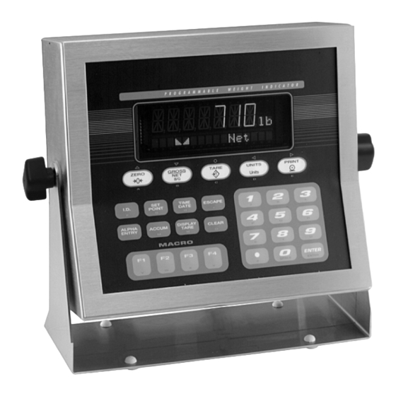
Page 6: Front Panel Display
(NE) Figure 1-1 shows the IQ plus 710 front panel keys and o r a l p h a e n t r y ( A E ) m o d e f o r s o m e the key functions assigned in normal mode. -
Page 7: Indicator Operations
Indicator Operations 1.3.7 Display or Change Time and Date To display the date, press the key once; TIME/DATE Basic IQ plus 710 operations are summarized below: press a second time to display the time. TIME/DATE 1.3.1 Toggle Gross/Net Mode To set the date, press the key once. -
Page 8: Installation
IQ plus 710. The power outlet supplying the indicator must be installed near the unit and be easily accessible. The IQ plus 710 provides five cord grips for cabling into the indicator: one for the power cord, three to Unpacking and Assembly... - Page 9 8. Next, remove connector J1 from the board. The connector plugs into a header on the board (see Figure 2-4). Wire the load cell cable from the Mark Position load cell or junction box to connector J1 as on Cable shown in Table 2-1.
- Page 10 RS485-A LOCATION OF INSTALLED ANALOG OUTPUT MODULE –I EPROM C100 LOAD C104 CELL COMP DIGITAL OUTPUT BROWN WIRE BLUE WIRE TO LINE FILTER Figure 2-4. IQ plus 710 CPU and Power Supply Board, Version 2.1 IQ plus 710 Installation Manual...
-
Page 11: Serial Communications
Figure 2-4 on page 6 and plug rather than source, switching current. Each output is a the module input into connector J5 on the IQ plus 710 normally open collector circuit, capable of sinking board. Connect the output cable to the analog output 250 mA when active. -
Page 12: Enclosure Reassembly
Dispose of batteries per manufacturer instruction. Figure 2-5. IQ plus 710 Enclosure Backplate Board Removal If you must remove the IQ plus 710 CPU board, use the following procedure: 1. Disconnect power to the indicator. Loosen cord grips and remove backplate as described in Section 2.2 on page 4. -
Page 13: Replacement Parts
Replacement Parts Table 2-5 lists replacement parts for the IQ plus 710, including all parts referenced in Figures 2-6 through 2-10. Number Description (Quantity) Figure 41397 Enclosure, sloped front (1) Figure 2-9 on page 13 41401 Enclosure, flat front (1) - Page 14 To protect against the risk of fire, replace fuses only with same type and rating fuse. Caution See Section 10.10 on page 74 for complete fuse specifications. Table 2-5. Replacement Parts (Continued) 10/3X 4/3X 7/3X 6/3X 115V/ 230V PLUG 51/4X GROUND STUDS Figure 2-6. Backplate Assembly IQ plus 710 Installation Manual...
- Page 15 POWER CORD Discontinued Product CABLE TIE 37/4X TO BACKPLATE GROUND STUD TO CPU BOARD P2 8/6X/D Figure 2-7. Enclosure and Line Filter Assembly Installation...
- Page 16 40/3X/C 5/6X/A Discontinued Product 38/4X SLOPED FRONT MODELS ONLY TO JUMPER JP4 Figure 2-8. Enclosure and CPU Board Assembly IQ plus 710 Installation Manual...
- Page 17 3/13X/B 44/3X Discontinued Product Figure 2-9. Bezel Assembly 29/4X 39/4X 27/2X 25/2X Figure 2-10. Tilt Stand Assembly Installation...
-
Page 18: Configuration
PC serial port to the RS-232 pins on Configuration Methods the indicator EDP port. The IQ plus 710 indicator can be configured by using 3. Power up the PC and the indicator. Use the setup the front panel keys to navigate through a series of switch to place the indicator in setup mode. -
Page 19: Front Panel Configuration
Front Panel Configuration The IQ plus 710 indicator can be configured using a series of menus accessed through the indicator front panel when the indicator is in setup mode. Table 3-1 summarizes the functions of each of the main menus. -
Page 20: Menu Structures And Parameter Descriptions
Menu Structures and Parameter Descriptions The following sections provide graphic representations of the IQ plus 710 menu structures. In the actual menu structure, the settings you choose under each parameter are arranged horizontally. To save page space, menu choices are shown in vertical columns. The factory default setting appears at the top of each column. Parameters shown surrounded by a dotted-line box only appear under the special circumstances explained under each box. -
Page 21: Configuration Menu
3.2.1 Configuration Menu CONFIG FORMAT CALIBR SERIAL PROGRM PFORMT SETPTS DIG IN ALGOUT VERS XXXXXXX XXXXXXX XXXXXXX XXXXXXX GRADS ZTRKBND ZRANGE MOTBAND OVRLOAD SMPRAT DIGFLT1 DIGFLT2 1.9% FS+2% 30HZ 10000 4.0% number 0.5D FS+1D 3.75HZ 0.6D 100% FS+9D 7.5HZ Discontinued Product 15HZ RATTRAP DFSENS... - Page 22 (DFSENS parameter) fall outside of this 20DD threshold, digital filtering is suspended. If NONE is selected, the filter is always enabled. 50DD 100DD 200DD 250DD NONE Table 3-2. Configuration Menu Parameters (Continued) IQ plus 710 Installation Manual...
-
Page 23: Format Menu
CONFIG Menu Parameter Choices Description ALGFLTR Analog filter. Selects the range used for filtering mechanical and electrical noise. 8 Hz value has a medium filtering effect; 2 Hz has the greatest effect. Normally, the minimum filter value that allows a stable display should be selected. If digital filtering is also used, select either 2 Hz or 8 Hz for this parameter. - Page 24 OZ=ounce; TN=short ton; T=metric ton; GN=grain; TROYOZ=troy ounce; TROYLB=troy pound; LT=long ton. 230 VAC indicators are configured with KG for both primary and secondary units. NOTE: TROYOZ TROYLB NONE Table 3-3. Format Menu Parameters IQ plus 710 Installation Manual...
- Page 25 FORMAT Menu Parameter Choices Description Secondary Units (SECNDR Parameter) DECPNT 888888.8 Decimal point location. Determines the location of the decimal point or dummy zeros in the 8888888 display. 8888880 8888800 8.888888 88.88888 888.8888 8888.888 88888.88 Discontinued Product DSPDIV Display divisions. Selects the value of minimum division size of the displayed weight. UNITS Specifies primary units for displayed and printed weight.
-
Page 26: Calibration Menu
Press Enter to remove an offset value from the zero and span calibrations. Use this parameter only after WZERO and WSPAN have been set. See Section 4.1 on page 37 for more information about using this parameter. Table 3-4. Calibration Menu Parameters IQ plus 710 Installation Manual... -
Page 27: Serial Menu
3.2.4 Serial Menu See Section 10.4 on page 68 for information about IQ plus 710 serial data formats. ALGOUT CONFIG FORMAT XXXXXXX CALIBR SERIAL PROGRM XXXXXXX SETPTS XXXXXXX DIG IN XXXXXXX VERS PFORMT PRNDEST BAUD BITS TERMIN EOLDLY BAUD BITS... - Page 28 Specifies whether the printer port sends the data stream to a network bus. Specify ON only if the Remote I/O or Profibus option is installed. STREAM Specifies whether data is streamed from the printer port. Table 3-5. Serial Menu Parameters (Continued) IQ plus 710 Installation Manual...
-
Page 29: Program Menu
3.2.5 Program Menu CONFIG FORMAT CALIBR SERIAL PROGRM PFORMT SETPTS DIG IN XXXXXXX ALGOUT VERS TARE100 DATE TIME CONSNUM CONSTUP DATEFMT DATESEP TIMEFMT TIMESEP number number MODE1 unit-ID MODE2 MMDDYY SLASH 12HOUR COLON MODE3 DDMMYY DASH 24HOUR COMMA Discontinued Product MODE4 YYMMDD SEMI... - Page 30 Zero key only. Specify ON to disable all front panel keys except ZERO in normal mode. See NOTE above ALPHAKB Alpha keyboard. Specify ON to enable alpha entry for the indicator keypad. If OFF is specified, the ALPHA ENTRY key is disabled. Table 3-6. Program Menu Parameters IQ plus 710 Installation Manual...
- Page 31 PROGRM Menu Parameter Choices Description PROMPTS PROMPT1– Specify prompts for use in macros and setpoint names. Prompts are referenced by the NAME PROMPT60 parameter under the MACRO and SETPTS submenus; prompts appear in the secondary display area during macro and setpoint execution. MACRO1 STRTBAT Specify MACROs 1–4.
-
Page 32: Print Format Menu
Display and edit active character and Decrement ASCII value Increment ASCII value ASCII value of active character of active character Enter numeric ASCII character value Press ENTER or to save value Figure 3-9. Print Format Menu IQ plus 710 Installation Manual... -
Page 33: Setpoints Menu
3.2.7 Setpoints Menu See Section 8.0 on page 55 for more information about configuring and using setpoints. CONFIG FORMAT CALIBR SERIAL PROGRM PFORMT SETPTS DIG IN XXXXXXX ALGOUT VERS SP CFG BATCHNG SETPT1 SETPT2 – SETPT20 AUTO MANUAL Same as SETPT1 Discontinued Product GROSSSP NETSP... - Page 34 INRANGE, –GROSS, –NET, and BATCHPR Setpoints VALUE ACCESS NAME DIGOUT number NONE NONE HIDE 1–8 1–60 COUNTER and AUTOJOG setpoints only Figure 3-13. Submenu for COUNTER, AUTOJOG, COZ, INMOTON, INRANGE, –GROSS, –NET, and BATCHPR Setpoints IQ plus 710 Installation Manual...
- Page 35 TIMER and CONCUR Setpoints START VALUE ACCESS DIGOUT NAME 0–65535 1–20 1–20 NONE NONE HIDE 1–60 1–8 Figure 3-14. Submenu for TIMER and CONCUR Setpoints Discontinued Product SETPTS Menu Parameter Choices Description Level 2 submenus SETPT1–SETPT8 Specifies the setpoint kind. GROSSSP GROSSSP, NETSP, +RELSP, –RELSP, and %RELSP setpoint kinds can be used as NETSP...
- Page 36 Specifies a weight equal to half the band width. The band established around the setpoint value is VALUE ±BANDVAL. HYSTER number GROSSSP, NETSP, and RELSP setpoint types: Specifies a band around the setpoint value that must be exceeded before the setpoint, once off, can trip on again. IQ plus 710 Installation Manual...
- Page 37 SETPTS Menu Parameter Choices Description PREACT GROSSSP, NETSP, and RELSP setpoint types: Allows the digital output associated with a setpoint to shut off before the setpoint is satisfied to allow for material in LEARN suspension. The ON value adjusts the setpoint trip value up or down (depending on the TRIP parameter setting) from the setpoint value.
-
Page 38: Digital Input Menu
ZERO ALPHAMD KEY7 NT/GRS ZERO CLEAR KEY8 TIME KEY9 DATE DSPTAR • • • • KEYDP CLRTAR IDKEY • • see DIGIN 3–8 for complete list of values KEY0 CLRACC Figure 3-15. Digital Input Menu IQ plus 710 Installation Manual... - Page 39 DIG IN Menu Parameter Choices Description Level 2 submenus DIGIN1 Specifies the function activated by digital inputs 1–8. Default values are: DIGIN1=BATSTRT; DIGIN2 ZERO DIGIN2=BATRUN; DIGIN3–DIGIN8=OFF. DIGIN3 NT/GRS • ZERO, NT/GRS (net/gross mode toggle), TARE, UNITS, and PRINT provide the same DIGIN4 TARE functions as the five major front panel keys.
-
Page 40: Analog Output Menu
Version menu: when selected, the indicator displays the installed software version number. CONFIG FORMAT XXXXXXX CALIBR SERIAL PROGRM PFORMT XXXXXXX SETPTS XXXXXXX DIG IN ALGOUT VERS Software version Figure 3-17. Version Menu IQ plus 710 Installation Manual... -
Page 41: Calibration
Calibration ™ The IQ plus 710 can be calibrated using the front panel, EDP commands, or the Revolution configuration utility. Each method consists of the following steps: • Zero calibration • Entering the test weight value • Span calibration •... -
Page 42: Edp Command Calibration
WVAL=nnnnnn<CR> 7. Send the KUPARROW or KEXIT EDP command to exit setup mode. 4. Send the WSPAN EDP command to calibrate span. The indicator displays while *CAL* calibration is in progress. IQ plus 710 Installation Manual... -
Page 43: Revolution Calibration
Revolution Calibration ™ 5. Enter the to be used for Value of Test Weight span calibration then click START To calibrate the indicator using Revolution, the 6. A dialog box asks whether hooks or chains indicator EDP port must be connected to a PC running are used to hang calibration test weights. -
Page 44: More About Calibration
126 000 147 000 168 000 189 000 210 000 231 000 252 000 273 000 294 000 315 000 420 000 525 000 735 000 1 050 000 Table 4-1. Ideal A/D Raw Counts IQ plus 710 Installation Manual... -
Page 45: Edp Commands
EDP Commands The IQ plus 710 indicator can be controlled by a Command Function personal computer or remote keyboard connected to KTARE Press the TARE key the indicator EDP port. Control is provided by a set of EDP commands that can simulate front panel key... -
Page 46: Reporting Commands
45 can be changed when in normal weighing mode. SPDUMP Print setpoint configuration VERSION Use the following command syntax when changing Write IQ plus 710 software version parameter values: Write current displayed weight with units identifier. See Section 10.2 on page 66 for command=value<ENTER> more information. - Page 47 Command Description Values PRI.DECPNT Primary units decimal position 8.888888, 88.88888, 888.8888, 8888.888, 88888.88, 888888.8, 8888888, 8888880, 8888800 PRI.DSPDIV Primary units display divisions 1D, 2D, 5D PRI.UNITS Primary units LB, KG, G, OZ, TN, T, GN, TROYOZ, TROYLB, LT, NONE SEC.DECPNT Secondary units decimal position 8.888888, 88.88888, 888.8888, 8888.888, 88888.88, 888888.8, 8888888, 8888880, 8888800 SEC.DSPDIV...
- Page 48 PROMPT#60 programming MACRO1.K01– Set MACRO1 keystroke MACRO1.K30 MACRO2.K01– Set MACRO2 keystroke MACRO2.K30 MACRO3.K01– Set MACRO3 keystroke MACRO3.K30 MACRO4.K01– Set MACRO4 keystroke MACRO4.K30 MACRO1.STRTBAT Start batch OFF, ON MACRO2.STRTBAT MACRO3.STRTBAT MACRO4.STRTBAT Table 5-7. PROGRM EDP Commands IQ plus 710 Installation Manual...
- Page 49 Command Description Values SETPOINT Setpoint number 1–20 KIND Setpoint kind OFF, GROSSSP, NETSP, +RELSP, –RELSP, %RELSP, PAUSE, DELAY, WAITSS, COUNTER, AUTOJOG, COZ, INMOTON, INRANGE, –GROSS, –NET, BATCHPR, TIMER, CONCUR VALUE Setpoint value number PSHTARE Push tare OFF, ON PSHPRINT Push print OFF, ON, WAITSS PSHACCM Push accumulate...
-
Page 50: Normal Mode Commands
Transmit net weight in non-displayed units Transmit tare weight in non-displayed units Query system error conditions nnnnn See Section 10.1 on page 65 for detailed information about the XE command response format. Table 5-13. Normal Mode EDP Commands IQ plus 710 Installation Manual... -
Page 51: Batching Control Commands
5.1.6 Batching Control Commands The commands listed below provide batching control through the EDP port. BATSTART If the BATRUN digital input is active (low) or not assigned, the BATSTART command can be used to start the batch program. BATRESET Stops the program and resets the batch program to the first batch step. Run the BATRESET command after making changes to the batch configuration. -
Page 52: Saving And Transferring Data
BAUD and BITS parameters on the for another IQ plus 710 and the attached scale is not SERIAL menu match the baud rate, bits, and parity changed, recalibration is not required. -
Page 53: Print Formatting
Print Formatting Commands Table 6-1 lists commands you can use to format the IQ plus 710 print formats. Commands included in the format strings must be enclosed between < and > delimiters. Any characters outside of the delimiters are printed as text on the ticket. -
Page 54: Default Ticket Formats
Default Ticket Formats Table 6-2 shows the default print formats for the IQ plus 710 and lists the conditions under which each print format is used. The HDRFMT format is used to specify header information that can be used by the other ticket formats. -
Page 55: Customizing Print Formats
NOTES: • Lower-case letters and some special characters cannot be displayed on the IQ plus 710 front panel and are shown as blanks. The IQ plus 710 can send or receive any ASCII character; the character printed depends on Print Formatting... - Page 56 Decrement ASCII value Increment ASCII value ASCII value of active character of active character Enter numeric ASCII character value Press ENTER or to save value Figure 6-2. PFORMT Menu, Showing Alphanumeric Character Entry Procedure IQ plus 710 Installation Manual...
-
Page 57: Truck Modes
Truck Modes The truck in/out modes are used to handle multiple allow you to manually enter the tare Keyed tares truck ID numbers and tare weights. Six truck modes weight using the numeric keypad and the key. TARE combine stored ID, keyed tare, and value swapping Keyed tares are available in Modes 1, 3, and 5. -
Page 58: Using The Truck Modes
. The indicator prints a PRINT weigh-out ticket (TRWOUT format) and automatically clears the information from memory: If the tare weight is a keyed tare, the word is printed after on the KEYED RECALLED tare line. IQ plus 710 Installation Manual... -
Page 59: Setpoints
Setpoints The IQ Plus 710 indicator provides twenty programmable setpoints for control of both indicator and external equipment functions. Setpoints are configured to trip based on specified conditions; tripping the setpoint can be used to request indicator functions (print, tare, accumulate) or to change the state of a digital output controlling external equipment. - Page 60 NOTE: If more than one concurrent setpoint is configured, each must be assigned to a different digital output. Table 8-1. Setpoint Kinds IQ Plus 710 Installation Manual...
-
Page 61: Batching Examples
Batching Examples Setpoint 5 is used to evaluate the gross amount of material in the hopper after dispensing, and to 8.2.1 Example 1 maintain a minimum material level in the hopper. The following example uses seven setpoints to When the hopper weight falls below 300 , digital dispense material from a hopper in 100 batches... -
Page 62: Example 2
SETPOINT=3 KIND=WAITSS PSHTARE=ON Setpoint 4 starts the fast fill operation. When the net weight reaches 175 , the setpoint trips and digital output 1 is set off. SETPOINT=4 KIND=NETSP VALUE=175 TRIP=HIGHER BATCH=ON DIGOUT=1 IQ Plus 710 Installation Manual... -
Page 63: Batching Switch
(mushroom button), and a run/ start/abort 3-way switch. WHITE Discontinued Product BLACK on IQ plus 710 CPU Board STOP/START MUSHROOM SWITCH Figure 8-3. Batching Switch Wiring Diagram To begin a batch process, turn the 3-way switch to momentarily. If the STOP button is pushed Figure 8-2. -
Page 64: Macro Programming
Up to four macro sequences can be programmed for • Macro steps are performed at the display update rate. the IQ Plus 710 indicator. Each macro provides a Configure the update rate (DSPRATE parameter on the simulation of up to 30 front panel key presses and can FORMAT menu) to 2 seconds (2SEC) or faster. - Page 65 PROGRM Menu Parameter Choices Description Level 2 MACRO submenu MACRO1 EDIT Configure macros MACRO2 STRTBAT MACRO3 MACRO4 Level 3 MACRO submenu EDIT macro sequence Create or display a macro sequence STRTBAT Specifies whether a batch sequence is automatically started when the macro Discontinued Product sequence ends.
-
Page 66: Macro Programming Examples
MACRO 1 SETPOINT=1 MACRO1.K01=PAUSREL.COMPR1 MACRO1.K01=NAME.1 KIND=GROSSSP MACRO1.K02=PAUSREL.WAITSS VALUE=5 MACRO1.K02=NAME.1 TRIP=HIGHER MACRO1.K03=KTARE BATCH=OFF MACRO1.K04=PAUSREL.COMPR2 DIGOUT=NONE MACRO1.K04=NAME.2 MACRO1.K05=PAUSREL.WAITSS SETPOINT=2 MACRO1.K06=KPRINT KIND=NETSP MACRO1.K07=KGROSS VALUE=200 MACRO1.K08=PAUSREL.AZTRACK TRIP=HIGHER MACRO1.K08=NAME.3 BATCH=OFF DIGOUT=NONE PROMPT#1=ADD BOX PROMPT#2=ADD MATERIAL IQ Plus 710 Installation Manual... -
Page 67: Example 2
1. The first macro step waits for an empty box to be placed on the scale. The prompt ADD BOX SETPOINT=3 shown on the secondary display until setpoint KIND=NETSP 1 changes state. VALUE=6.5 2. The second macro step continues to display TRIP=HIGHER the prompt on the secondary display... - Page 68 The macro shown below is started when the digital output from setpoint 6 goes active (DO3 wired to DI3): MACRO1.K01=PAUSREL.COMPR7 MACRO1.K01=NAME.4 MACRO1.K02=PAUSREL.WAITSS MACRO1.K03=KTARE MACRO1.K04=PAUSREL.COMPR8 MACRO1.K04=NAME.5 MACRO1.K05=PAUSREL.WAITSS MACRO1.K06=PAUSREL.MOTION MACRO1.K06=NAME.6 MACRO1.K07=PAUSREL.TIMER MACRO1.K07=NAME.7 MACRO1.K07=TIMEOUT.600 MACRO1.K08=PAUSREL.TIMER MACRO1.K08=NAME.8 MACRO1.K08=TIMEOUT.600 MACRO1.K09=PAUSREL.WAITSS MACRO1.K09=NAME.9 MACRO1.K10=PAUSREL.COMPR9 MACRO1.K10=NAME.10 IQ Plus 710 Installation Manual...
-
Page 69: Appendix
10.1 Error Messages The IQ plus 710 indicator provides a number of error messages. When an error occurs, the message is shown on the indicator display. Error conditions can also be checked remotely by using the XE EDP command as described in Section 10.1.2. -
Page 70: 10.2 Status Messages
The XE EDP command can be used to remotely query Two EDP commands, P and ZZ, can be used to the IQ plus 710 for the error conditions shown on the provide status about the indicator. front panel. The XE command returns a decimal •... -
Page 71: 10.3 Tare And Zero Key Functions
10.3 TARE and ZERO Key Functions The function of the front panel TARE and ZERO keys depends on the value specified for the REGULAT parameter on the PROGRM menu. Table 10-3 describes the function of these keys for each of the regulatory modes. -
Page 72: 10.4 Data Formats
10.4 Data Formats If the initiating device address matches the port address of an IQ plus 710 on the RS-485 network, that 10.4.1 Continuous Output Serial Data Format indicator responds. For example, with demand If continuous transmission is configured for the EDP... -
Page 73: 10.5 Digital Filtering
10.5 Digital Filtering Standard digital filtering uses mathematical averaging • DFSENS specifies the number of consecutive scale readings that must fall outside the filter to eliminate the variant digital readings that the A/D threshold (DFTHRH) before digital filtering converter sends periodically because of external is suspended. -
Page 74: 10.6 Conversion Factors For Secondary Units
10.6 Conversion Factors for Secondary Units The IQ plus 710 has the capability to mathematically Primary Unit x Multiplier Secondary Unit convert a weight into many different types of units pounds 7000.00 grains and instantly display those results with a press of the key. -
Page 75: 10.7 Analog Output Calibration
Primary Unit x Multiplier Secondary Unit Primary Unit x Multiplier Secondary Unit troy ounces grains troy pounds 5760 grains 31.10348 grams 373.2417 grams 0.031103 kilograms 0.373242 kilograms 1.09714 ounces 13.16571 ounces 0.068571 pounds 0.822857 pounds 0.083333 troy pounds troy ounces Table 10-4. -
Page 76: 10.8 Test Mode
Press and hold the setup switch, then press the 0 key to reset configuration and calibration parameters to factory default values. Load cells must be recalibrated before using the indicator (see Section 4.0 on page 37). Table 10-5. Test Menu Functions IQ plus 710 Installation Manual... -
Page 77: 10.9 Software Revision Information
EXIT Press the 3 key to exit test mode. Table 10-5. Test Menu Functions (Continued) 10.9 Software Revision Information Version 2.1 of the IQ plus 710 software provides the following additional support: • New SMPRAT parameter on the CONFIG menu provides selectable A/D conversion rate ranging from 3.75–30 Hz. -
Page 78: 10.10 Specifications
R76-2 Test Certificate TC5678 active-low Accuracy Class : 10 000 Digital Outputs 8 outputs, open collector with TTL pullup, 250 mA sink, 40V withstand Digital Filter Software selectable: 1–256, enhanced ® ® Rattletrap hybrid digital filtering LISTED IQ plus 710 Installation Manual... -
Page 79: Iq Plus 710 Limited Warranty
IQ plus 710 Limited Warranty Rice Lake Weighing Systems (RLWS) warrants that all RLWS equipment and systems properly installed by a Distributor or Original Equipment Manufacturer (OEM) will operate per written specifications as confirmed by the Distributor/OEM and accepted by RLWS. All systems and components are warranted against defects in materials and workmanship for two years. - Page 80 Discontinued Product...
- Page 81 Discontinued Product...
- Page 82 Discontinued Product PN 64505 06/10...
Need help?
Do you have a question about the IQ plus 710 and is the answer not in the manual?
Questions and answers