
Related Manuals for Rice Lake SURVIVOR IQ F Series


Summary of Contents for Rice Lake SURVIVOR IQ F Series
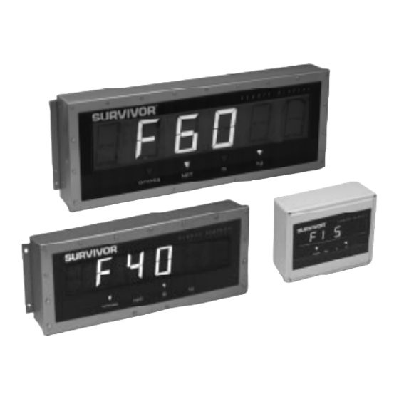
- Page 1 F-Series SURVIVOR ® Flip Digit Remote Displays Models F15, F40, and F60 Version 1.1 Installation Manual 43545...
-
Page 2: Table Of Contents
5.4 Replacement Parts ........................... 14 Specifications ..........................15 F-Series Remote Displays Limited Warranty..................16 Copyright © 1999 Rice Lake Weighing Systems. All rights reserved. Printed in the United States of America. Specifications subject to change without notice. Version 1.1, July 1999... -
Page 3: About This Manual
Authorized distributors and their employees installation. can view or download this manual from the This manual applies to units using Version 1.1 of the Rice Lake Weighing Systems distributor F-Series remote display software. site at www.rlws.com Introduction Optional Features The F-Series flip digit remote displays provide... -
Page 4: Pre-Installation Setup
Pre-Installation Setup 2.1.1 RS-232 The F-Series remote displays should be set up, configured, and tested before delivery to the Figure 2-2 on page 3 shows the connections required installation site. for RS-232 communications to the remote display. See the manual for your indicator to determine the This section describes RS-232 and 20 mA current i n d i c a t o r p i n... - Page 5 Remote Display Remote Display Terminal Block Terminal Block Passive 20 mA RS-232 Current Loop Shield Shield Indicator Indicator Serial Port Serial Port Chassis Ground Chassis Ground Figure 2-2. RS-232 Indicator Connections to Remote Display Terminal Block Figure 2-3. 20 mA Current Loop Connections: Passive Remote Display, Active Indicator Remote Display Remote Display...
-
Page 6: Configuration
Configuration 3.2.1 Serial Communications T h e r e m o t e d i s p l a y a n d i n d i c a t o r s h o u l d b e connected, configured, and tested before delivery to DSW1 switches set the serial communications the installation site. -
Page 7: Primary And Secondary Units
3.2.2 Primary and Secondary Units Switches DSW2-1 through DSW2-4 set the primary and secondary annunciators for the remote display. Using these switches, the lb and kg annunciators can Primary Secondary be assigned to designate pounds, kilograms, tons, or units units Model metric tons (megagrams). -
Page 8: Display Characteristics
the zeroes removed. For example, a baud rate Set switch DSW3-2 on to enable display of input error of 9600 is shown as b 96 messages. Section 5.1 on page 12 lists the F-Series input and self-test error messages. 6. Once the display determines the data format being used, the message is shown. -
Page 9: Suppress Leading Zeroes
Setting the Clock (for Units with the 3.2.7 Suppress Leading Zeroes Switch DSW3-6 enables suppression of leading Time Option Installed) zeroes in weight values of less than 1. If DSW3-6 is Once remote display configuration is complete and the set on, weight values of less than 1 are shown with unit powered on, set the clock by doing the following: only one zero to the left of the decimal point. - Page 10 MSI TransWeigh 6260 Ohaus 1-10, 1-20W Ohaus 1-5S Ohaus 1150 Pennsylvania 3100 Pennsylvania 5600 Pyrel HR500K Rice Lake Weighing Systems stream format Streeter Amet 9000 Transcell (RL-100, TI-500) Weightronix WI-110, WI-120 Weightronix WI-125 Weightronix WI-127 (default layout 6) Western DF1000 Table 3-5.
-
Page 11: On-Site Installation
On-Site Installation This section describes procedures for sealing the For Models F40 and F60, securing the cover requires enclosure and dimensions for mounting the F-Series 15 (F40) or 17 (F60) bolts, all torqued to 20 in-lbs. remote displays. Ensure that the remote display has Use the torquing patterns shown in Figures 4-1 and been tested and works with the indicator before 4-2 to prevent distorting the cover gasket. -
Page 12: Mounting The Enclosure
Mounting the Enclosure Remote Display Self-Test Figur es 4-3 th rough 4- 5 sh ow th e e n c l o s u re When the remote display is powered on, the unit goes dimensions, mounting hole diameters, and distances through the following self-test procedure: on center between mounting holes for each of the 1. - Page 13 32.0" 31.0" 5.50" 2.25" SURVIVOR R E M O T E D I S P L A Y 8.0" 12.5" 11.94" GROSS 4 x ø .38" 30.25" Figure 4-4. Model F40 Enclosure Dimensions 44.0" 43.0" 5.62" 2.25" SURVIVOR R E M O T E D I S P L A Y 9.75"...
-
Page 14: Troubleshooting And Repair
Troubleshooting and Repair Error Messages Table 5-1 lists error messages shown by the F-Series remote displays. The FAIL x messages indicate errors encountered during the power-on self-test sequence; input error messages are shown only if DIP switch DSW3-2 is set on. Message Meaning Cause / Correction... -
Page 15: Board Diagrams
20mA/RxD JMP1 LED1 +20 mA IN –20 mA IN 20 mA RxD +20 mA OUT EEPROM 20 mA TxD –20 mA OUT RICE LAKE WEIGHING SYSTEMS 5V pull-up 15V pull-up EPROM TIME & DATE MODULE RS-232 DSW1 DSW2 DSW3 DSW4 Figure 5-2. -
Page 16: Loop-Back Self-Test
Loop-Back Self-Test • For 20 mA communications, ensure that 20 mA chips are installed correctly and the The F-Series remote displays provide a loop-back jumper at JMP1 is on. See Figure 2-1 on page self-test for use in diagnosing serial communications 2 for component locations. -
Page 17: Specifications
Specifications Power Optional Features Line Voltages 115 or 230 VAC (+10% / –15%) Time (12/24 hour selectable) Temperature (displays °C and °F) Frequency 50 or 60 Hz Power Consumption (115 VAC models) Backlighting Base model (no options installed): Visor (F40 and F60 only) Model F15: 18 W / 150 mA Environmental Model F40: 52 W / 450 mA... -
Page 18: F-Series Remote Displays Limited Warranty
F-Series Remote Displays Limited Warranty Rice Lake Weighing Systems (RLWS) warrants that all RLWS equipment and systems properly installed by a Distributor or Original Equipment Manufacturer (OEM) will operate per written specifications as confirmed by the Distributor/OEM and accepted by RLWS. All systems and components are warranted against defects in materials and workmanship for one year.
Need help?
Do you have a question about the SURVIVOR IQ F Series and is the answer not in the manual?
Questions and answers