Table of Contents
Advertisement
Quick Links
Advertisement
Table of Contents

Related Manuals for Rice Lake LaserLight Series


Summary of Contents for Rice Lake LaserLight Series
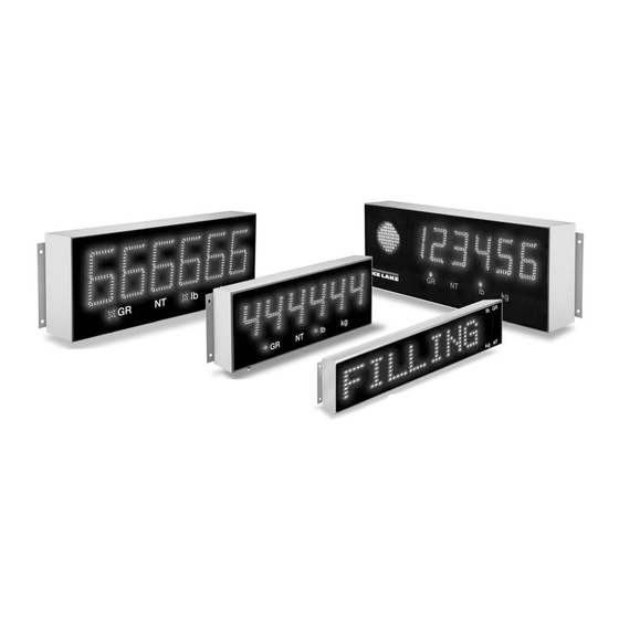
- Page 1 LaserLight Series ® Remote Displays Version 2.05 Installation Manual 4'' Stop/Go Remote Display 6'' Remote Display 4'' Remote Display M-Series Messaging Remote Display (Available in Stainless Steel) 8-character (Shown) or 12-character October 2, 2019 PN 75936 Rev C...
- Page 2 All information contained within this publication is, to the best of our knowledge, complete and accurate at the time of publication. Rice Lake Weighing Systems reserves the right to make changes to the technology, features, specifications and design of the equipment without notice.
-
Page 3: Table Of Contents
Replacement Parts ................. . 29 Technical training seminars are available through Rice Lake Weighing Systems. - Page 4 6.0 Specifications ............... . . 39 Rice Lake continually offers web-based video training on a growing selection of product-related topics at no cost.
-
Page 5: Introduction
Do not operate or work on this equipment unless this manual has been read and all instructions are understood. Failure to follow the instructions or heed the warnings could result in injury or death. Contact any Rice Lake Weighing Systems dealer for replacement manuals. -
Page 6: Overview
The LaserLight remote display features a super-bright LED display and non-glare filtered lens for use in a wide variety of applications. The LaserLight Series are available with a 7-segment, 6-digit display or an eight or 12-character matrix display. The LaserLight remote display is designed to work with most digital weight indicators, host computers, and peripherals using a 20 mA current loop, RS-232 or RS-485 communications. -
Page 7: Annunciators
• Red, green circle and green arrow annunciators indicate the traffic light state on the display; Feature applies to only the LaserLight 4-SG Optional Traffic Light Display LED Annunciators Figure 1-2. 7-Segment Front Panel Display Arrow Annunciators Figure 1-3. Matrix Display Front Panel © Rice Lake Weighing Systems ● All Rights Reserved... -
Page 8: Installation/Setup
Unpacking and Assembly Immediately after unpacking, visually inspect the LaserLight remote display for damage. If parts were damaged in shipment, notify Rice Lake Weighing Systems and the shipper immediately. The main components of the LaserLight remote display include: • Powder coated steel or stainless steel enclosure •... -
Page 9: Enclosure Disassembly
Once the enclosure is secured, slide the mounting plate down to allow it to hang freely from the enclosure with the tabs secured against the pins. This enables the user to continue wiring the remote display. © Rice Lake Weighing Systems ● All Rights Reserved... -
Page 10: Wiring
LaserLight Series Wiring The LaserLight remote display provides three cord grips located on the underside of the enclosure for cabling, one for the power cord (supplied) and two for serial communications. The LaserLight remote display is pre-wired. Only the serial communications cable must be connected. -
Page 11: Serial Wiring
7. Make cable connections for RS-232, RS-485, or 20 mA current loop communications. 8. Tighten the serial cable cord grip. Step 6 Step 4 Step 5 Figure 2-7. Serial Cord Grip Assembly © Rice Lake Weighing Systems ● All Rights Reserved... - Page 12 LaserLight Series RF Interference If experiencing RF Interference, follow the instructions below. 1. Loop the serial wires through the cylindrical ferrite (PN 66730) provided with this manual. 2. Using the plastic cable ties provided, secure the wires to the ferrite and the serial cable to the learn switch wires to keep ferrite from contacting the CPU board.
-
Page 13: 20 Ma Current Loop
Ensure transmit and receive jumpers are across TX0 485 and RX0 485 (Figure 2-10). Port 0 Jumpers/TX and RX LEDs Port 1 Jumpers/TX LEDs Reset Switch 20 mA Active/Passive Selector Switches Figure 2-10. Jumper Pin Locations (Board Revision G and Later) © Rice Lake Weighing Systems ● All Rights Reserved... -
Page 14: Reset Switch
LaserLight Series 2.4.6 Reset Switch The reset switch enables a simulated power up reset. It goes back to normal operation mode. The reset switch eliminates having to unplug the unit to do a reset, see Figure 2-10 on page 9 for the reset switch location on the CPU board. -
Page 15: Configuration
To begin configuration, open the enclosure, see Section 2.2 on page 5 for enclosure disassembly instructions, to access the CPU board (Figure 3-1 Figure 3-2 on page 12). Figure 3-1. LaserLight CPU Board © Rice Lake Weighing Systems ● All Rights Reserved... - Page 16 LaserLight Series The setup button is located on the secondary display board (Figure 3-2). Jumper position for decimal point or comma Setup button Figure 3-2. Setup Button Location on Secondary Display Board (7-Segment Display) The display board is mounted on a hinged mounting plate to allow for easy access to the CPU board. Press the SETUP button to access main menu configuration parameters.
- Page 17 Figure 3-5. Configuration Main Menu Choices With the 8 and 12-character matrix displays some of the labels are not shortened, for example STDSTL in the Note 7-segment is STAND STILL on the 12-character display. © Rice Lake Weighing Systems ● All Rights Reserved...
- Page 18 LaserLight Series CONFIG Menu 7-Segment 8-Character 12-Character Display Parameter Matrix Display Matrix Display Choices Description Level 2 Submenus TIMDAT TIMEDATE TIME/DATE Enabled To enable time and date Format Displays USA or ISO time format Sets hours/minutes and month/day/year Date Can disable date...
-
Page 19: Serial Communications
SECU GROSSC NETC SP IND MOTION number number A - Z A - Z A - Z A - Z A - Z between 5-75 between 5-75 Figure 3-6. Serial Menu © Rice Lake Weighing Systems ● All Rights Reserved... - Page 20 LaserLight Series Serial Menu Parameter Choices Description Level 2 Submenus Port 0 BAUD Configure Port 0; See Level 3 submenu parameter descriptions PARITY DATA BITS STOP BITS HOLD WT Keeps last weight displayed if communication is lost and prevents the remote display from going into an error condition...
- Page 21 Toledo numbered model indicator, set to one. Toledo 8142 format bit-mapped status data Inclinometer custom program Flex-Weigh DWM IV Fairbanks 2500/and 9401 compatible units AnD 4323 Table 3-5. Port 0 Serial Menu © Rice Lake Weighing Systems ● All Rights Reserved...
-
Page 22: Testing The Remote Display
LaserLight Series Testing the Remote Display Serial Menu Port 1 Parameter Choices Description Level 3 submenus BAUD 1200 Baud rate; Selects the transmission speed for Port 1 2400 4800 9600 19200 PARITY Selects the parity of data transmitted from Port 1... -
Page 23: Digital Outputs
If communications are successful between the two, Pass displays on the remote display. Version When Version is selected from the main menu choices the current software version displays on the remote display. SERIAL CONFIG TEST VERSION Figure 3-9. Version Menu © Rice Lake Weighing Systems ● All Rights Reserved... -
Page 24: Demand Print Displaying
LaserLight Series Demand Print Displaying The indicator and the LaserLight remote display can be set up to do a demand print display for such applications as cattle weighing. This is useful if to maintain the last weight of an animal. -
Page 25: Command Format (7-Segment)
Get the version number: example return “2.05” |00GV! Set the temperature adjustment |00TP#! Where # is -5 +5 (example |00TP-1!, |00TP+3!, |00TP5) default is 0 – Dump the configuration parameters (test purposes only): |00GDC! © Rice Lake Weighing Systems ● All Rights Reserved... -
Page 26: Set Or Get The Digital I/O (7-Segment With Stop/Go Light)
LaserLight Series 3.7.2 Set or Get the Digital I/O (7-Segment with Stop/Go Light) Version 2.05 only accepts the serial digital I/O commands listed in this manual. All previous serial Digital I/O Note commands prior to Version 2.05 do not work properly with this product. -
Page 27: Display Message Command Format (Matrix Display)
If the real time clock is disabled in the remote display, an error message is sent back Table 3-11. Display Message Command Format Examples: Scroll the message “Rice Lake Weighing Systems” twice: |00DM|0|N|N|Y|2|Rice Lake Weighing Systems! Slide on and flash the message “DRIVE AHEAD” for 5 seconds: |00DM|5000|Y|Y|N|0|DRIVE AHEAD! ©... -
Page 28: Options
LaserLight Series Options Several options are available with the LaserLight remote display: • Time and date (Standard on 4", 6" and 4"SG models) • Temperature The Time-Date and Temperature options display in three-second cycles (along with weight) when displayed weight is Note zero or below. -
Page 29: Temperature
Screw, Mach 3/8-16NC (4" Model - 3) (6" Model - 6) NOTE: See Figure 4-3 on page 26 for the Part Kit Illustration. Table 4-1. Parts Kit Contents (4" and 6" Models) © Rice Lake Weighing Systems ● All Rights Reserved... - Page 30 LaserLight Series Item No. Part No. Description 85034 Weldment, Pole Mounting (8-Character Model - 1) 85035 Weldment, Pole Mounting (12-Character Model - 1) 14635 Nut, Lock 1/4-20NC Hex (4) 14747 Bolt, 3/8-16NCx2-3/4 Hex (1) 14955 Screw, Cap 1/4-20NCx1/2 (4) 15019...
-
Page 31: Traffic Light Option
Figure 4-4. Back of the LaserLight 4-SG Remote Display, CPU Board Location and Traffic Light Option Traffic Light Board LaserLight CPU Board Corresponding Signal Location J1 Location J1 Wire Color 5 VDC DIG O Green DIG 1 White Black Table 4-3. Traffic Light Wiring © Rice Lake Weighing Systems ● All Rights Reserved... -
Page 32: Dry Contact Wiring
LaserLight Series 4.5.1 Dry Contact Wiring The DIG 0 and DIG 1 pins on the traffic light board (pin 2 and pin 3 on connector J1) have pull up resistors to ensure the operation of the traffic light can be controlled by switching the DIG 0 or DIG 1 (or both) to ground. -
Page 33: Appendix
Invalid Settings Invalid settings upon power up; All settings reset to their default state RError RError Range Error Range Error When the Rice Lake format goes over or under range Table 5-1. Error Messages Replacement Parts For LaserLight Remote Display Replacement Parts, see the following information: 5.2.1 UL Approved Replacement Parts Figure 5-1. -
Page 34: 7-Segment Display Replacement Parts
LaserLight Series 5.2.2 7-Segment Display Replacement Parts BROWN BLUE See Detail A GRN/YEL See Detail B DETAIL B DETAIL A 26 or 30 SEE DETAIL C SEE DETAIL C 4" and 6" Remote Display Traffic Light LED Remote Display Figure 5-2. 4'', 4-SG and 6'' Remote Display Parts Illustration www.RiceLake.com... - Page 35 103651 Board Assembly, LED Traffic (4-SG'' Model) 14839 Screw, Mach 6-32 NC x 1/4 (4-SG'' Model) 193696 Cable Gland Assembly, 1/2 NPT Nickel Plated Brass Table 5-3. 4'', 4-SG'' and 6'' Remote Display Parts List © Rice Lake Weighing Systems ● All Rights Reserved...
- Page 36 LaserLight Series CPU Board Removed For Clarity To Enclosure 43 42 43 6'' LED Remote Display See Detail A See Detail D See Detail A To Enclosure Detail A 4'' LED Remote Display See Detail A See Detail D Cable tie must be...
-
Page 37: And 12-Character Display Replacement Parts
Appendix 5.2.3 8 and 12-Character Display Replacement Parts See Grounding Brown Blue Detail Brown Blue Green/Yellow Grounding Detail To Power Figure 5-4. 8 and 12 Character LaserLight Assembly Parts Illustration © Rice Lake Weighing Systems ● All Rights Reserved... - Page 38 LaserLight Series Item No. Part No. Description Qty. 84844 Enclosure, 8 Digit Laser 84847 Enclosure, 12 Digit Laser 75569 Bracket, Inside Terminal 44744 Terminal Block, 3 Position 15630 Locknut, 1/2 NPT Black 94613 Lens, Display Front Red 53308 Label, 1.25x1.25 8000T...
- Page 39 Appendix Figure 5-5. 8 and 12 Character LaserLight Assembly Parts Illustration (Continued) © Rice Lake Weighing Systems ● All Rights Reserved...
- Page 40 LaserLight Series Item No. Part No. Description Qty. 40672 Wire Assembly, Ground 9'' 75860 Cable Assembly, Power Supply 75861 Switch Assembly, Push Button 45043 Wire, Ground 4'' with No. 8 76246 Cable Assembly, 6 Position, 8 Digit Laser 76246 Cable Assembly, 6 Position, 12 Digit Laser...
-
Page 41: Laserlight Remote Display Enclosure Dimensions
0.5" 23.0" 6.0" 9.25" 4 x Ø.31 22.0" 5.0" Figure 5-6. 4" Model Enclosure Dimensions 32.0" 31.0" 0.5" 12.25" 7.75" 30.0" 4 x Ø.31 5.0" Figure 5-7. 6" Model Enclosure Dimensions © Rice Lake Weighing Systems ● All Rights Reserved... -
Page 42: Laserlight Matrix Display Enclosure Dimensions
LaserLight Series LaserLight Matrix Display Enclosure Dimensions 23.00" 22.00" 4x Ø.38 6.25" 3.25" 5.00" 24.00" Figure 5-8. 3M8 Enclosure Dimensions 31.00" 30.00" 4 x Ø.38 3.25" 6.25" 5.00" 32.00" Figure 5-9. 3M12 Enclosure Dimensions www.RiceLake.com Visit our website... -
Page 43: Specifications
22 lb (10 kg) 4-SG-character 25 lb (11 kg) Material Weather proof, mild steel, powder coated Warranty 2-year limited warranty Certifications and Approvals UL Approval for UL Models Only ® File Number: E355385 © Rice Lake Weighing Systems ● All Rights Reserved... - Page 44 LaserLight Series www.RiceLake.com Visit our website...
- Page 46 Specifications subject to change without notice. Rice Lake Weighing Systems is an ISO 9001 registered company. 230 W. Coleman St. • Rice Lake, WI 54868 • USA U.S. 800-472-6703 • Canada/Mexico 800-321-6703 • International 715-234-9171 • Europe +31 (0)26 472 1319...
Need help?
Do you have a question about the LaserLight Series and is the answer not in the manual?
Questions and answers