Rice Lake IQ PLUS 710 Installation Manual
Digital weight indicator
Hide thumbs
Also See for IQ PLUS 710:
- Installation manual (82 pages) ,
- Installation manual (76 pages) ,
- Quick start manual (2 pages)
Table of Contents
Advertisement
Quick Links
Advertisement
Table of Contents

Subscribe to Our Youtube Channel
Related Manuals for Rice Lake IQ PLUS 710


Summary of Contents for Rice Lake IQ PLUS 710
-
Page 1: Installation Manual
IQ plus ® Digital Weight Indicator Version 2.0 Installation Manual 64505... -
Page 3: Table Of Contents
Zero Deadload A/D Counts............39 Copyright © 2000 Rice Lake Weighing Systems. All rights reserved. Printed in the United States of America. - Page 4 10.11 Specifications..............79 IQ plus 710 Limited Warranty ........................ 80...
-
Page 5: About This Manual
Revolution ª conÞguration utility. See Section 3.1 on IQ plus 710. Please leave the Operator Card with the page 13 for information about conÞguration methods. indicator when installation and conÞguration are complete. -
Page 6: Front Panel Display
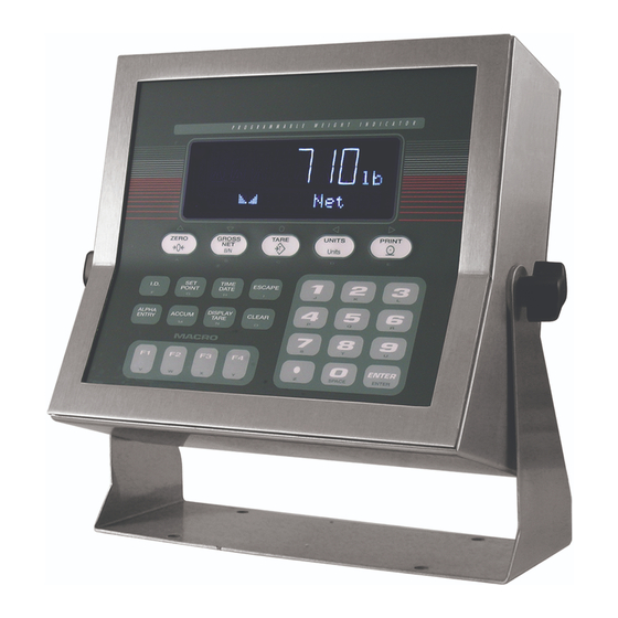
Figure 1-1. IQ plus 710 Front Panel Front Panel Display Figure 1-1 shows the IQ plus 710 front panel keys and The two-digit annunciator also displays whether the indicator is in numeric entry (NE) or alpha entry the key functions assigned in normal mode. -
Page 7: Indicator Operations
Indicator Operations 1.3.7 Display or Change Time and Date To display the date, press the key once; TIME/DATE Basic IQ plus 710 operations are summarized below: press a second time to display the time. TIME/DATE 1.3.1 Toggle Gross/Net Mode To set the date, press the key once. -
Page 8: Installation
Cable Connections indicator must be installed near the unit and be easily accessible. The IQ plus 710 provides Þve cord grips for cabling into the indicator: one for the power cord, four to Unpacking and Assembly accommodate load cell, communications, digital I/O, Immediately after unpacking, visually inspect the IQ and analog output cables. -
Page 9: Load Cells
C100 C104 DIGITAL OUTPUT BROWN WIRE BLUE WIRE TO LINE FILTER Figure 2-1. IQ plus 710 CPU and Power Supply Board, Version 2 2.3.1 Load Cells To attach cable from a load cell or junction box, J1 Pin Function remove connector J1 from the board. The connector plugs into a header on the board (see Figure 2-1). -
Page 10: Serial Communications
Figure 2-1 on page 5 and plug rather than source, switching current. Each output is a the module input into connector J5 on the IQ plus 710 normally open collector circuit, capable of sinking board. Connect the output cable to the analog output 250 mA when active. -
Page 11: Enclosure Reassembly
PC. Figure 2-2. IQ plus 710 Enclosure Backplate Board Removal If you must remove the IQ plus 710 CPU board, use the following procedure: 1. Disconnect power to the indicator. Loosen cord grips and remove backplate as described in Section 2.2 on page 4. -
Page 12: Replacement Parts
Replacement Parts Table 2-5 lists replacement parts for the IQ plus 710, including all parts referenced in Figures 2-3 through 2-7. Number Description (Quantity) Figure 41397 Enclosure, sloped front (1) Figure 2-6 on page 12 41401 Enclosure, flat front (1) - Page 13 Number Description (Quantity) Figure — 42104 7-position connectors for J1, J4, and J12 (3) Figure 2-1 on page 5 — 46420 10-position connectors for J7 and J8 (2) — 45484 160 mA TR5 subminiature fuses (2), 115 VAC F1 and F2 in Figure 2-1 on page 5 45107 80 mA TR5 subminiature fuses (2), 230 VAC * Additional parts included in parts kit.
- Page 14 POWER CORD CABLE TIE 37/4X TO BACKPLATE GROUND STUD TO CPU BOARD P2 8/6X/D Figure 2-4. Enclosure and Line Filter Assembly IQ plus 710 Installation Manual...
- Page 15 40/3X/C 5/6X/A 38/4X SLOPED FRONT MODELS ONLY TO JUMPER JP4 Figure 2-5. Enclosure and CPU Board Assembly Installation...
- Page 16 3/13X/B 44/3X Figure 2-6. Bezel Assembly 29/4X 39/4X 27/2X 25/2X Figure 2-7. Tilt Stand Assembly IQ plus 710 Installation Manual...
-
Page 17: Configuration
Configuration Methods mode. The IQ plus 710 indicator can be conÞgured by using 4. Start the Revolution program. the front panel keys to navigate through a series of Figure 3-1 shows an example of one of the Revolution conÞguration menus or by sending commands or... - Page 18 Front Panel Configuration The IQ plus 710 indicator can be conÞgured using a series of menus accessed through the indicator front panel when the indicator is in setup mode. Table 3-1 summarizes the functions of each of the main menus.
-
Page 19: Menu Structures And Parameter Descriptions
Menu Structures and Parameter Descriptions The following sections provide graphic representations of the IQ plus 710 menu structures. In the actual menu structure, the settings you choose under each parameter are arranged horizontally. To save page space, menu choices are shown in vertical columns. The factory default setting appears at the top of each column. Parameters shown surrounded by a dotted-line box only appear under the special circumstances explained under each box. -
Page 20: Configuration Menu
10000 number 0.5D 100% FS+1D FS+9D RATTRAP DFSENS DFTHRH ALGFLTR PWRUPMD TAREFN 8OUT BOTH 10DD DELAY 16OUT NOTARE 20DD 32OUT PBTARE 50DD 64OUT KEYED 128OUT 100DD 2OUT 200DD 4OUT 250DD NONE Figure 3-4. ConÞguration Menu IQ plus 710 Installation Manual... - Page 21 CONFIG Menu Parameter Choices Description Level 2 submenus GRADS 10000 Specifies the number of full scale graduations. The value entered must be in the range number 1–100000 and should be consistent with legal requirements and environmental limits on system resolution. To calculate GRADS, use the formula, GRADS = Capacity / Display Divisions.
-
Page 22: Format Menu
8888880 number 1SEC 8888888 8888880 8888800 1500MS 2SEC 8.888888 8888800 2500MS 88.88888 8.888888 888.8888 88.88888 3SEC TROYOZ 4SEC 8888.888 888.8888 TROYOZ TROYLB 6SEC 88888.88 8888.888 TROYLB 888888.8 88888.88 8SEC NONE NONE Figure 3-5. Format Menu IQ plus 710 Installation Manual... - Page 23 FORMAT Menu Parameter Choices Description Level 2 submenus PRIMAR DECPNT Specifies the decimal position, display divisions, and units used for the primary units. See DSPDIV Level 3 submenu parameter descriptions. UNITS SECNDR DECPNT Specifies the decimal position, display divisions, units, and conversion multiplier used for the DSPDIV secondary units.
- Page 24 See Section 10.7 on page 74 for a list of multipliers. keyboard To toggle between primary and secondary units, press the UNITS key. Table 3-3. Format Menu Parameters (Continued) IQ plus 710 Installation Manual...
-
Page 25: Calibration Menu
3.2.3 Calibration Menu See Section 4.0 on page 36 for calibration procedures. CONFIG XXXXXXX FORMAT CALIBR SERIAL PROGRM XXXXXXX PFORMT SETPTS XXXXXXX DIGIN XXXXXXX ALGOUT VERS WZERO WVAL WSPAN WLIN REZERO *CALIB* CALIB* *CALIB* Display and edit Display and edit Press Enter to Display and edit test weight value... -
Page 26: Serial Menu
3.2.4 Serial Menu See Section 10.4 on page 70 for information about IQ plus 710 serial data formats. ALGOUT CONFIG FORMAT XXXXXXX CALIBR SERIAL PROGRM XXXXXXX SETPTS XXXXXXX DIG IN XXXXXXX VERS PFORMT PRNDEST BAUD BITS TERMIN EOLDLY BAUD BITS... - Page 27 SERIAL Menu Parameter Choices Description Level 3 Submenus EDP Port BAUD 9600 Baud rate. Selects the transmission speed for the EDP port. 19200 1200 2400 4800 BITS 8NONE Selects number of data bits and parity of data transmitted from the EDP port. 7EVEN 7ODD TERMIN...
-
Page 28: Program Menu
Allows selection of time format and separator character. See Level 3 submenu parameter TIMESEP descriptions. Use the TIME/DATE key or the ST EDP command to set the time. See Section 5.0 on page 40 for information about using the EDP commands. Table 3-6. Program Menu Parameters IQ plus 710 Installation Manual... - Page 29 PROGRM Menu Parameter Choices Description CONSNUM Consecutive numbering. Allows sequential numbering for print operations. The consecutive number number value is incremented following each print operation that includes <CN> in the ticket format. When the consecutive number is reset, it is reset to the value specified on the CONSTUP parameter.
- Page 30 SLASH Specifies the date separator character. DASH SEMI TIMEFMT 12HOUR Specifies the format used to display or print the time. 24HOUR TIMESEP COLON Specifies the time separator character. COMMA Table 3-6. Program Menu Parameters (Continued) IQ plus 710 Installation Manual...
-
Page 31: Print Format Menu
3.2.6 Print Format Menu See Section 6.0 on page 48 for information about custom print formatting. ALGOUT CONFIG FORMAT CALIBR SERIAL PROGRM XXXXXXX PFORMT SETPTS XXXXXXX DIG IN VERS HDRFMT GFMT NFMT TRWIN TRWOUT SPFMT EDPFMT Same as GFMT Display first 7 Scroll left in format string Scroll right in format string characters of format... -
Page 32: Setpoints Menu
Same as SETPT1 GROSSSP NETSP +RELSP –RELSP %RELSP PAUSE DELAY WAITSS Go to A Go to B COUNTER AUTOJOG INMOTON INRANGE –GROSS –NET BATCHPR Go to C TIMER CONCUR Go to D Figure 3-10. Setpoints Menu IQ plus 710 Installation Manual... - Page 33 GROSSSP, NETSP, +RELSP, –RELSP, and %RELSP Setpoints RELNUM PREACT PREVAL VALUE TRIP BANDVAL HYSTER 1–20 number number HIGHER number number LOWER If TRIP=INBAND If PREACT= ON RELSP setpoints only or OUTBAND or LEARN LEARN INBAND OUTBAND PSHACCM PSHPRNT PSHTARE ALARM ACCESS NAME DIGOUT...
- Page 34 Batching enable. Set to AUTO or MANUAL to allow a batch sequence to run. AUTO MANUAL requires a BATSTRT digital input, BATSTART EDP command, or STRTBAT MANUAL macro configuration before the batch sequence can run. AUTO allows batch sequences to repeat continuously. Table 3-7. Setpoint Menu Parameters IQ plus 710 Installation Manual...
- Page 35 SETPTS Menu Parameter Choices Description Level 3 submenus GROSSSP VALUE Configure GROSSSP, NETSP, and RELSP setpoints. See Figure 3-11 on page 29 NETSP TRIP and Level 4 parameter descriptions. +RELSP BANDVAL –RELSP HYSTER %RELSP PREACT PREVAL RELNUM BATCH PSHACCM PSHTARE PSHPRNT ALARM ACCESS...
- Page 36 TIMER and CONCUR setpoint types: Specifies the ending setpoint number. Do not specify the number of the TIMER or CONCUR setpoint itself. The TIMER or CONCUR setpoint stops when the ending setpoint begins. Table 3-7. Setpoint Menu Parameters (Continued) IQ plus 710 Installation Manual...
-
Page 37: Digital Input Menu
SETPTS Menu Parameter Choices Description ACCESS All setpoint types: Specifies whether the SETPOINT key can be used to change the HIDE setpoint value in normal mode, including macro simulations of pressing the SETPOINT key. ON: Value can be displayed and changed HIDE: Value cannot be displayed or changed OFF: Value can be displayed but not changed Setpoints with ACCESS=ON can be turned on or off when a batch is not running:... - Page 38 KBDLOC TIME/DATE key once; TIME simulates pressing the key twice. HOLD • CLRTAR clears the current tare. CLRCN • CLRACC clears the accumulator. GROSS PRIM TIME DATE CLRTAR CLRACC Table 3-8. Digital Input Menu Parameters IQ plus 710 Installation Manual...
-
Page 39: Analog Output Menu
3.2.9 Analog Output Menu The ALGOUT menu is used only if the analog output option is installed. If the analog output option is installed, conÞgure all other indicator functions and calibrate the indicator before conÞguring the analog output. See Section 10.8 on page 75 for analog output calibration procedures. CONFIG XXXXXXX FORMAT... -
Page 40: Calibration
Calibration ª The IQ plus 710 can be calibrated using the front panel, EDP commands, or the Revolution conÞguration utility. Each method consists of the following steps: ¥ Zero calibration ¥ Entering the test weight value ¥ Span calibration ¥... -
Page 41: Edp Command Calibration
Linearization is optional: if you choose not to 7. The optional rezero function is used to perform linearization, skip WLIN remove a calibration offset when hooks or parameter; if linearization values have chains are used to hang the test weights. previously been entered, these values are reset ¥... -
Page 42: Revolution Calibration
Þlled in. Click to save the new Exit values and return to the Revolution main Figure 4-2. Revolution Calibration Display menu; to restore the previous calibration values (including linear calibration values), click Restore Settings IQ plus 710 Installation Manual... -
Page 43: More About Calibration
More About Calibration 4.4.2 Zero Deadload A/D Counts Table 4-1 lists the ideal A/D counts that result from The following topics provide additional information input signals of 0Ð45 mV with zero deadload. Actual about compensating for environmental factors values will typically be higher than the values shown (Section 4.4.1) and checking the calibration of an in Table 4-1 but the ideal values can be used when indicator with no attached scale (Section 4.4.2). -
Page 44: Edp Commands
EDP Commands The IQ plus 710 indicator can be controlled by a Command Function personal computer or remote keyboard connected to KUNITS Press the UNITS key the indicator EDP port. Control is provided by a set of EDP commands that can simulate front panel key... -
Page 45: Reporting Commands
All load cell calibration settings are lost when NOTE: VERSION the RESETCONFIGURATION command is run. Write IQ plus 710 software version Write current displayed weight with units identifier. See Section 10.2 on page 68 for more information. Write one frame of stream format Table 5-2. - Page 46 300, 600, 1200, 2400, 4800, 9600, 19200 PRN.BITS Printer port data bits/parity 8NONE, 7EVEN, 7ODD PRN.TERMIN Printer port termination character CR/LF, CR PRN.EOLDLY Printer port end-of-line delay 0–255 (0.1-second intervals) PRN.HANDSHK Printer port handshaking OFF, ON Table 5-6. SERIAL EDP Commands IQ plus 710 Installation Manual...
- Page 47 Command Description Values PRN.BUS Printer port bus network enable OFF, ON PRN.STREAM Printer port streaming OFF, ON PRNDEST Print destination EDP, PRN, BOTH Table 5-6. SERIAL EDP Commands (Continued) Command Description Values Set date MMDDYY or DDMMYY (enter using DATEFMT specified) Set time hhmm (enter using 24-hour format) DATEFMT...
- Page 48 Set digital output nn off (inactive) DOFF#0 Set all digital outputs off (inactive) For commands ending with “#nn”, nn is the digital output (01–8) being set on or off. Table 5-10. DIG OUT EDP Commands IQ plus 710 Installation Manual...
-
Page 49: Normal Mode Commands
Command Description Values DIGIN1 Digital input function OFF, ZERO, NT/GRS, TARE, UNITS, PRINT, ACCUM, SETPNT, DIGIN2 TIMDATE, ESC, ALPHAMD, CLEAR, DSPTAR, IDKEY, KF1–KF4, DIGIN3 KEY0–KEY9, KEYDP, ENTER, BATRUN, BATSTRT, BATPAUS, DIGIN4 KBDLOC, HOLD, CLRCN, GROSS, NET, PRIM, SEC, TIME, DATE, DIGIN5 CLRTAR, CLRACC DIGIN6... -
Page 50: Batching Control Commands
@ – O Low order bits of byte 12 are set on to indicate active digital inputs setpoint alarm status. Bits are assigned as shown at right. Carriage Return (CR) Table 5-14. BATSTATUS Command Structure IQ plus 710 Installation Manual... -
Page 51: Saving And Transferring Data
Table 5-15. ASCII Translation Table for BATSTATUS Data Saving and Transferring Data 5.2.2 Downloading Configuration Data from PC to Connecting a personal computer to the IQ plus 710 Indicator EDP port allows you to save indicator conÞguration ConÞguration data saved on a PC or ßoppy disk can data to the PC or to download conÞguration data from... -
Page 52: Print Formatting
Print Formatting Commands Table 6-1 lists commands you can use to format the IQ plus 710 print formats. Commands included in the format strings must be enclosed between < and > delimiters. Any characters outside of the delimiters are printed as text on the ticket. -
Page 53: Default Ticket Formats
Default Ticket Formats Table 6-2 shows the default print formats for the IQ plus 710 and lists the conditions under which each print format is used. The HDRFMT format is used to specify header information that can be used by the other ticket formats. -
Page 54: Customizing Print Formats
. For ENTER shown as blanks. The IQ plus 710 can send or receive example, to check the current conÞguration of the any ASCII character; the character printed depends on GFMT format, type GFMT and press . - Page 55 ALGOUT CONFIG FORMAT CALIBR SERIAL PROGRM XXXXXXX PFORMT SETPTS XXXXXXX DIG IN VERS HDRFMT GFMT NFMT TRWIN EDPFMT TRWOUT SPFMT Same as GFMT Display first 7 Scroll left in format string Scroll right in format string characters of format Press ENTER or to insert a Press CLEAR to delete the active character...
-
Page 56: Truck Modes
Stored IDs and tare weights are available in Modes 3, 4, 5, and 6. PROGRM TARE100 MODE 1 MODE 2 MODE 3 MODE 4 MODE 5 MODE 6 Figure 7-1. TARE100 Truck Mode Selections IQ plus 710 Installation Manual... -
Page 57: Using The Truck Modes
Using the Truck Modes 7.1.2 Modes 3, 4, 5, and 6 In modes 3Ð6, the indicator stores the tare weights and All the truck in/out modes let you quickly search the ID numbers in memory until you manually erase memory for a speciÞc ID number. ID information can them. -
Page 58: Setpoints
A/D update. If the input channel weight reading matches the setpoint value, the indicator sets the corresponding digital output on. are active one at a time, in an ordered sequence. The IQ plus 710 can use batch setpoints to Batch setpoints control up to twenty separate batch processing steps. - Page 59 Kind Description Batch Continuous Setpoint turned off/ignored. Ö Ö GROSSSP Gross setpoint. Trips when the current gross weight matches this value. Ö Ö NETSP Net setpoint. Trips when the current net weight matches this value. Ö Ö +RELSP Positive relative setpoint. Trips at a specific value above the referenced setpoint. Ö...
- Page 60 NOTE: If more than one concurrent setpoint is configured, each must be assigned to a different digital output. Table 8-1. Setpoint Kinds (Continued) IQ plus 710 Installation Manual...
-
Page 61: Batching Examples
Batching Examples Setpoint 5 is used to evaluate the gross amount of material in the hopper after dispensing, and to 8.2.1 Example 1 maintain a minimum material level in the hopper. The following example uses seven setpoints to When the hopper weight falls below 300 , digital dispense material from a hopper in 100 batches... -
Page 62: Example 2
SETPOINT=3 KIND=WAITSS PSHTARE=ON Setpoint 4 starts the fast Þll operation. When the net weight reaches 175 , the setpoint trips and digital output 1 is set off. SETPOINT=4 KIND=NETSP VALUE=175 TRIP=HIGHER BATCH=ON DIGOUT=1 IQ plus 710 Installation Manual... -
Page 63: Batching Switch
START WHITE GREEN BLACK EMERGENCY STOP on IQ plus 710 CPU Board STOP/START MUSHROOM SWITCH Figure 8-3. Batching Switch Wiring Diagram IN-STOP OUT-RUN To begin a batch process, turn the 3-way switch to momentarily. If the STOP button is pushed START Figure 8-2. -
Page 64: Macro Programming
Macro Programming Up to four macro sequences can be programmed for NOTES: the IQ plus 710 indicator. Each macro provides a ¥ Macro steps are performed at the display simulation of up to 30 front panel key presses and can update rate. - Page 65 PROGRM Menu Parameter Choices Description Level 2 MACRO submenu MACRO1 EDIT Configure macros MACRO2 STRTBAT MACRO3 MACRO4 Level 3 MACRO submenu EDIT macro sequence Create or display a macro sequence STRTBAT Specifies whether a batch sequence is automatically started when the macro sequence ends.
-
Page 66: Macro Programming Examples
F1 macro key: prompts used by the macro. MACRO 1 SETPOINT=1 MACRO1.K01=PAUSREL.COMPR1 KIND=GROSSSP MACRO1.K01=NAME.1 VALUE=5 MACRO1.K02=PAUSREL.WAITSS TRIP=HIGHER MACRO1.K02=NAME.1 BATCH=OFF MACRO1.K03=KTARE DIGOUT=NONE MACRO1.K04=PAUSREL.COMPR2 MACRO1.K04=NAME.2 SETPOINT=2 MACRO1.K05=PAUSREL.WAITSS KIND=NETSP MACRO1.K06=KPRINT VALUE=200 MACRO1.K07=KGROSS TRIP=HIGHER MACRO1.K08=PAUSREL.AZTRACK BATCH=OFF MACRO1.K08=NAME.3 DIGOUT=NONE IQ plus 710 Installation Manual... -
Page 67: Example 2
1. The Þrst macro step waits for an empty box to SETPOINT=3 be placed on the scale. The prompt ADD BOX KIND=NETSP is shown on the secondary display until VALUE=6.5 setpoint 1 changes state. TRIP=HIGHER 2. The second macro step continues to display BATCH=ON the prompt on the secondary... - Page 68 The macro shown below is started when the digital output from setpoint 6 goes active (DO3 wired to DI3): MACRO1.K01=PAUSREL.COMPR7 MACRO1.K01=NAME.4 MACRO1.K02=PAUSREL.WAITSS MACRO1.K03=KTARE MACRO1.K04=PAUSREL.COMPR8 MACRO1.K04=NAME.5 MACRO1.K05=PAUSREL.WAITSS MACRO1.K06=PAUSREL.MOTION MACRO1.K06=NAME.6 MACRO1.K07=PAUSREL.TIMER MACRO1.K07=NAME.7 MACRO1.K07=TIMEOUT.600 MACRO1.K08=PAUSREL.TIMER MACRO1.K08=NAME.8 MACRO1.K08=TIMEOUT.600 MACRO1.K09=PAUSREL.WAITSS MACRO1.K09=NAME.9 MACRO1.K10=PAUSREL.COMPR9 MACRO1.K10=NAME.10 IQ plus 710 Installation Manual...
-
Page 69: Example 3
9.2.3 Example 3 Next, three macros are programmed to allow The following example describes how a series of reassignment of the setpoint values for each of the macros can be programmed to provide single-key three products. reprogramming of setpoint values. Table 9-2 shows Each macro uses the key to change the SETPOINT... - Page 70 MACRO3.K12=K1 MACRO2.K07=KENTER MACRO3.K13=K0 MACRO2.K08=KSETPOINT MACRO3.K14=KENTER MACRO3.K15=KSETPOINT MACRO2.K09=PAUSREL.TIMER MACRO2.K09=NAME.2 MACRO3.K16=PAUSREL.TIMER MACRO2.K09=TIMEOUT.20 MACRO3.K16=NAME.3 MACRO3.K16=TIMEOUT.20 MACRO2.K10=KGROSSNET MACRO2.K11=K2 MACRO3.K17=KGROSSNET MACRO2.K12=K5 MACRO3.K18=K3 MACRO2.K13=K0 MACRO3.K19=K1 MACRO2.K14=KENTER MACRO3.K20=K0 MACRO2.K15=KSETPOINT MACRO3.K21=KENTER MACRO2.K16=PAUSREL.TIMER MACRO3.K22=KESCAPE MACRO2.K16=NAME.2 MACRO3.K23=KESCAPE MACRO2.K16=TIMEOUT.20 MACRO2.K17=KGROSSNET MACRO2.K18=K3 MACRO2.K19=K5 MACRO2.K20=K0 MACRO2.K21=KENTER MACRO2.K22=KESCAPE MACRO2.K23=KESCAPE IQ plus 710 Installation Manual...
-
Page 71: Appendix
10.1 Error Messages The IQ plus 710 indicator provides a number of error messages. When an error occurs, the message is shown on the indicator display. Error conditions can also be checked remotely by using the XE EDP command as described in Section 10.1.2. -
Page 72: Using The Xe Edp Command
The XE EDP command can be used to remotely query Two EDP commands, P and ZZ, can be used to the IQ plus 710 for the error conditions shown on the provide status about the indicator. front panel. The XE command returns a decimal ¥... -
Page 73: 10.3 Tare And Zero Key Functions
10.3 TARE and ZERO Key Functions The function of the front panel TARE and ZERO keys depends on the value speciÞed for the REGULAT parameter on the PROGRM menu. Table 10-3 describes the function of these keys for each of the regulatory modes. -
Page 74: 10.4 Data Formats
If the initiating device address matches the port If continuous transmission is conÞgured for the EDP address of an IQ plus 710 on the RS-485 network, that or printer port (STREAM parameter on the SERIAL indicator responds. For example, with demand... -
Page 75: 10.5 Ascii Character Chart
10.5 ASCII Character Chart Use the decimal values for ASCII characters listed in Tables 10-4 and 10-5 when specifying print format strings on the IQ plus 710 PFORMT menu. The actual character printed depends on the character mapping used by the output device. - Page 76 Ç • È º ƒ ± ¾ ³ ® £ ™ ó š õ ˜ ¸ ž » • ° Ø · … † ¢ £ ´ Ä Table 10-5. ASCII Character Chart (Part 2) IQ plus 710 Installation Manual...
-
Page 77: 10.6 Digital Filtering
10.6 Digital Filtering ¥ DFSENS speciÞes the number of consecutive scale readings that must fall outside the Þlter Standard digital Þltering uses mathematical averaging threshold (DFTHRH) before digital Þltering to eliminate the variant digital readings that the A/D is suspended. converter sends periodically because of external ¥... -
Page 78: 10.7 Conversion Factors For Secondary Units
10.7 Conversion Factors for Secondary Units The IQ plus 710 has the capability to mathematically Primary Unit x Multiplier Secondary Unit convert a weight into many different types of units and pounds 7000.00 grains instantly display those results with a press of the key. -
Page 79: 10.8 Analog Output Calibration
Primary Unit x Multiplier Secondary Unit Primary Unit x Multiplier Secondary Unit troy ounces grains troy pounds 5760 grains 31.10348 grams 373.2417 grams 0.031103 kilograms 0.373242 kilograms 1.09714 ounces 13.16571 ounces 0.068571 pounds 0.822857 pounds 0.083333 troy pounds troy ounces Table 10-6. -
Page 80: 10.9 Test Mode
Press and hold the setup switch, then press the 0 key to reset configuration and calibration parameters to factory default values. Load cells must be recalibrated before using the indicator (see Section 4.0 on page 36). Table 10-7. Test Menu Functions IQ plus 710 Installation Manual... -
Page 81: 10.10 Software Revision History
Setpoints ¥ Streamed weight information now uses the following units designators: lb=L; Kg=K; oz=O; ¥ The IQ plus 710 now supports up to 20 gram=G; ton, metric ton, and long ton=T; grain, setpoints, including all setpoint kinds available troy ounce, troy pound, and none=space. - Page 82 WAITSS releases when the scale is stable within the speciÞed motion band. ¥ MOTION pause release function on PAUSREL submenu changed to release when motion is detected. ¥ Setpoint compare values expanded to 20 (COMPR1ÐCOMPR20). IQ plus 710 Installation Manual...
-
Page 83: Specifications
10.11 Specifications Serial Communications EDP Port Full duplex RS-232 or RS-485 Power Printer Port Full duplex RS-232 or active 20 mA current Line Voltages 115 or 230 VAC loop output Both Ports 19 200, 9600, 4800, 2400, 1200, 600, 300 Frequency 50 or 60 Hz bps;... -
Page 84: Iq Plus 710 Limited Warranty
IQ plus 710 Limited Warranty Rice Lake Weighing Systems (RLWS) warrants that all RLWS equipment and systems properly installed by a Distributor or Original Equipment Manufacturer (OEM) will operate per written speciÞcations as conÞrmed by the Distributor/OEM and accepted by RLWS. All systems and components are warranted against defects in materials and workmanship for two years.
Need help?
Do you have a question about the IQ PLUS 710 and is the answer not in the manual?
Questions and answers