
Related Manuals for Rice Lake LaserLight


Summary of Contents for Rice Lake LaserLight
- Page 1 LaserLight ® M-Series and 4-SG LED Remote Displays Version 2.05 Installation & Operation Manual 75936...
-
Page 3: Table Of Contents
5.4 LaserLight Remote Display Enclosure Dimensions ........ -
Page 5: Introduction
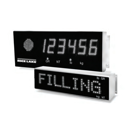
7-segment remote display is available in 4" or 6" digit sizes and the matrix display is available in 2.5" character size with 8 or 12 positions. The LaserLight 4-SG remote display comes in a 4" digit size in a 6"... -
Page 6: Annunciators
• Red, green circle and green arrow annunciators indicate the traffic light state on the display. This feature applies to only the LaserLight 4-SG. Optional traffic light display annunciators Figure 1-1. 7-Segment Front Panel Display Arrow annunciators Figure 1-2. Matrix Display Front Panel LaserLight Remote Display Installation & Operation Manual... -
Page 7: Mounting Plate Installation And Setup
Mounting Plate Installation and Setup LaserLight remote display can be easily set up and configured once mounted to a wall or pole. This section describes basic installation, AC wiring, RS-232, RS-485, and 20 mA current loop connections. Once installation setup is complete, go to Section 3.0 for information on configuring the remote display. -
Page 8: Wall Mounting
Ribbon cables connect the CPU board to the digit display boards. An A/C power cord is also supplied. Only the serial communications cable must be connected. Use the following steps to wire the remote display. The LaserLight remote display has no on/off switch. Before opening the unit, ensure the power cord is W arning disconnected from the power outlet. -
Page 9: Ac Wiring
2.4.1 AC Wiring LaserLight power supply can run on either 115 or 230 VAC. The AC wiring is run through the cord grip to a 3-position AC terminal block bracket on the inside of the enclosure (shown in Figure 2-4). This bracket can be removed by loosening the two standoffs and lifting it off. -
Page 10: Serial Wiring
2. Using the plastic cable ties provided, secure the wires to the ferrite and the serial cable to the learn switch wires to keep ferrite from contacting the CPU board. See Figure 2-7 below. Cylindrical ferrite Plastic cable ties Figure 2-7. Cylindrical Ferrite Placement LaserLight Remote Display Installation & Operation Manual... - Page 11 Table 2-2. Serial Communications Wiring NOTES: •Terminals J6, J8, and J9 are removable screw terminal plugs. •Port 0 is used for input only and port 1 is used to drive the next LaserLight Remote Display. See Table 2-2 above. Mounting Plate Installation and Setup...
-
Page 12: 20 Ma Current Loop
Figure 2-8 shows the LaserLight remote display CPU board. Figure 2-8. LaserLight Remote Display CPU Board Port 0 which is connected to the indicator supports three configurations; 20 mA, RS-232, and RS-485 communications. Port 1 which is the Echo port, supports 20 mA and RS-232 communications. -
Page 13: Reset Switch
2.4.6 Reset Switch The reset switch enables a simulated power up reset. It then goes back to normal operation mode. The reset switch eliminates having to unplug the unit to do a reset. Refer to Figure 2-8 on page 7 for the reset switch location on the CPU board. -
Page 14: Configuration
To begin configuration, open the enclosure (See Section 2.2 on page 3 for enclosure disassembly instructions), to access the CPU board (Figure 3-1) and digit display board (Figure 3-2). Figure 3-1. LaserLight CPU Board LaserLight Remote Display Installation & Operation Manual... - Page 15 Configuration • Serial communications • Test • Version LaserLight remote display can be configured and displayed using a series of menus accessed using internal buttons located on the secondary display and shown in Figure 3-3. SETUP ENTER LEFT RIGHT DOWN Figure 3-3.
- Page 16 TEST Test. System hardware tests VERSION VERSION Version. Displays installed software version number Table 3-1. LaserLight Remote Display Menu Summary TEST SERIAL CONFIG Figure 3-4. LaserLight Main Menu Options When configuring the indicator attached to the remote display, ensure that the decimal point configuration is compatible with the remote display.
- Page 17 CONFIG Menu 7-Segment Display 8-Character Matrix 12-Character matrix Choices Description Parameter Display Display Level 2 Submenus TIMDAT TIMEDATE TIME/DATE Enabled To enable time and date Format Displays USA or ISO time format Sets hours/minutes and month/day/year Date Can disable date TEMP TEMP TEMPERATURE...
-
Page 18: Serial Communications
Port 1 - Provides echoing OF INDICATOR DATA There are 15 sub-parameters associated with Port 0 and six sub-parameters associated with Port 1 which are shown in Figure 3-6 on page 15. See Section 2.4.2 for serial wiring positions. LaserLight Remote Display Installation & Operation Manual... - Page 19 SERIAL CONFIG TEST PORT0 PORT1 LOCK BAUD PARITY DATA ECHO STOP 1200 2400 Even 4800 None 9600 19200 LOCK LW POS BAUD P ARITY D ATA STOP E CHAR HOLD WT number 1200 between 5-50 Of f Of f 2400 Even 4800 None...
- Page 20 19200 PARITY PARITY PARITY Selects the parity of data of Port 0 EVEN NONE DATA DATABITS DATA BITS Selects the number of data bits of Port 0 Table 3-5. Port 0 Serial Menu LaserLight Remote Display Installation & Operation Manual...
- Page 21 Serial Menu 7-Segment 8-Character 12-Character Display Display Display Parameters Parameters Parameters STOP STOPBITS STOP BITS Selects the number of stop bits of Port 0 HOLD WT HOLD WT HOLD WEIGHT Select On to enable this feature to keep the last weight displayed if communication is lost or you are using demand updated weight and prevents remote display from going into an error condition.
- Page 22 LOCK If this parameter is disabled, the echo port display uses the same communications settings as the indicator port after an Auto-Learn is run. Table 3-6. Port 1 Serial Menu Parameters LaserLight Remote Display Installation & Operation Manual...
-
Page 23: Testing The Remote Display
Testing the Remote Display LaserLight remote display provides a test to check the hardware of the remote display. These tests can be accessed through the main menu (Figure 3-7). SERIAL CONFIG TEST DISPLY DIGOUT DIGIN LOOP BK HH-red circle LL-OFF... -
Page 24: Loop Back
LaserLight Remote Display Installation & Operation Manual... -
Page 25: Command Format (7-Segment)
The remote display also accepts serial commands to return the current time and date or to set the time and date to a new setting. This information can be used in conjunction with user programs in the 920i to ensure the indicator and remote display have the same time and date settings. -
Page 26: Display Message Command Format (Matrix Display)
Example: |ST08:00:00 2003-01-31! Get digital input state Get digital output state Get relay state. Relay 0-3, 0=Off=LL, state 1=LH, state 2=HL, state 3=On=HH. Set relay state (output relays only). Relay 0-1, state 1=On & 0=Off. LaserLight Remote Display Installation & Operation Manual... -
Page 27: Set Or Get The Digital I/O
Command Description Get the number of 5 x 7 Max6953 boards (0 = 7-seg, 2, 3 = 5 x 7) Get the version number Dump configuration parameters (for testing purposes only) Temperature adjustment. Allows +/- 5% degree adjustment Time and date is sent from the remote display depending on the current remote display time and date format: Time and date are sent to the remote display in ISO format. -
Page 28: Options
Figure 4-2 shows the remote display with the optional visor installed. Figure 4-2. LaserLight Remote Display w/ Optional Visor Installed (7-Segment Display) Set the visor (PN 75854 - 4" model & the 8-character matrix display) or (PN 75855 - 6" model & the 12-character matrix display) on top of the remote display and attach the visor using screws and plastic washers provided. -
Page 29: Pole Mount Kit
NOTE: The 6" LaserLight remote display uses four brackets (PN 76999) and the 4", 8- & 12-character display uses two. 2. Use the enclosed 3/8-16NC bolt (PN 14747), to attach the clinching pole brackets together using washers and lock nuts. - Page 30 Poles 4” - 8” Dia. 3 11 Holes for two brackets on each side of pole for 6” LaserLight r emote display Figure 4-3. LaserLight Pole Mount Assembly LaserLight Remote Display Installation & Operation Manual...
-
Page 31: Traffic Light Option
NOTE: a reset to the Laserlight CPU board will set the D0 and D1 pins on the Laserlight CPU (pins 5 and 6 on J1) to a high pulled up state therefore, the default state of the traffic light will be a stop light (red). -
Page 32: Single Switch Wiring
5. Connect the remaining switch pole to the digital ground of the indicator (if a common ground between the indicator and the Laserlight does not exist i.e.: fiber optic communication is used, then an additional wire will be needed for connecting the switch to the ground on the Laserlight CPU). -
Page 33: Appendix
Appendix Error Messages LaserLight remote display provides several error messages. When an error occurs, the message is shown on the display. NOTE: Some of the actual error messages displayed by the remote display are cryptic and are represented in Table 5-1 as closely as possible with plain text. - Page 34 Post only, slotted black (1) 76514 6-position screw terminal (1) 76513 4-position screw terminal (1) 72997 CPU board (1) 76226 Ribbon cable, 1 inch (1) 75936 Installation manual (1) Table 5-2. Selected Replacement Parts LaserLight Remote Display Installation & Operation Manual...
- Page 35 Reference Number Part Number Description Model Figure Number 15602 12 inch ground wire (1) 6" model Figure 5-3 74867 Enclosure, steel (1) 74868 Plate, bottom gusset (1) 75847 Component plate, vertical (1) 74882 Primary display board (1) 74883 Secondary display board (1) 76247 6-position cable (1) Figure 5-2...
- Page 36 6-position cable (1) Figure 5-4 103651 Board assembly LED, traffic (1) 104283 Ribbon cable, 20” (1) 104284 Cable, CPU traffic (1) 104240 Lens, 6” LaserLight gray Table 5-3. 4-SG Model Selected Replacement Parts LaserLight Remote Display Installation & Operation Manual...
- Page 37 Figure 5-3. 7-Segment Replacement Parts - Detail C Appendix...
-
Page 38: 12-Character Display Replacement Parts
Figure 5-4. 7-Segment Replacement Parts - Enclosure Bottom Figure 5-5. 7-Segment Replacement Parts - 6 ” Assembly LaserLight Remote Display Installation & Operation Manual... - Page 39 Figure 5-6. Wiring Appendix...
- Page 40 Power supply cable (1) 14833 Screw, MACH, 4-40 NC x 1/2 (2) 45302 Standoff, 8-32 NC (2) * Identifies quantity for the 12-character display 75936 Installation manual (1) Table 5-4. 8- & 12-Digit Replacement Parts LaserLight Remote Display Installation & Operation Manual...
- Page 41 Reference Number Part Number Description Model Figure Number 84847 Enclosure, steel (1) 12-Character Figure 5-7 38 Display 74870 Gasket, mounting plate UV (1) 76247 Cable (1) Figure 5-8 39 84848 Bottom plate (1) 84849 component plate (1) Table 5-4. 8- & 12-Digit Replacement Parts Appendix...
-
Page 42: Laserlight Remote Display Enclosure Dimensions
33 34 35 Brown Blue Brown Blue Green/Yellow To Power Figure 5-7. 8-Character LaserLight Assembly LaserLight Remote Display Installation & Operation Manual... - Page 43 Figure 5-8. 8-Character LaserLight Assembly Appendix...
- Page 44 4 x Ø.31 " 22.0 " Figure 5-9. 4" Model Enclosure Dimensions " 32.0 " " 31.0 " 7.75 " 12.25 " 30.0 " 4 x Ø.31 Figure 5-10. 6" Model Enclosure Dimensions LaserLight Remote Display Installation & Operation Manual...
-
Page 45: Laserlight Matrix Display Enclosure Dimensions
LaserLight Matrix Display Enclosure Dimensions " 23.00 " 22.00 " 6.25 " 4x Ø.38 3.25 " 5.00 " 24.00 Figure 5-11. 3M8 Enclosure Dimensions " 31.00 " 30.00 " " 6.25 4 x Ø.38 3.25 " 5.00 " 32.00 Figure 5-12. 3M12 Enclosure Dimensions... -
Page 46: Specifications
4" (101.6 mm): 20 lb (9 kg) 6" (152.4 mm): 25 lb (11 kg) 8-character: 16 lb (7kg) 12-character: 22 lb (10kg) 4-SG-character: 25 lb (11kg) Operating Temperature Range -40°F to 120°F (-40°C to 48.8°C) Warranty 2-year limited warranty LaserLight Remote Display Installation & Operation Manual... - Page 47 LaserLight Remote Display Limited Warranty Rice Lake Weighing Systems (RLWS) warrants that all RLWS equipment and systems properly installed by a Distributor or Original Equipment Manufacturer (OEM) will operate per written specifications as confirmed by the Distributor/OEM and accepted by RLWS. All systems and components are warranted against defects in materials and workmanship for two years.
Need help?
Do you have a question about the LaserLight and is the answer not in the manual?
Questions and answers