Rice Lake IQ plus 710 Installation Manual
Digital weight indicator
Hide thumbs
Also See for IQ plus 710:
- Installation manual (82 pages) ,
- Installation manual (84 pages) ,
- Quick start manual (2 pages)
Table of Contents
Advertisement
Quick Links
Advertisement
Table of Contents

Related Manuals for Rice Lake IQ plus 710


Summary of Contents for Rice Lake IQ plus 710
-
Page 1: Installation Manual
IQ plus ® Digital Weight Indicator Version 1.4 Installation Manual 45391... -
Page 2: Table Of Contents
4.4.1 Zero Deadload A/D Counts ........................ 36 4.4.2 Calculating the Span Coefficient ......................36 Copyright © 2000 Rice Lake Weighing Systems. All rights reserved. Printed in the United States of America. Specifications subject to change without notice. Version 1.4, March 2000... - Page 3 Conversion Factors for Secondary Units..................67 10.7 Analog Output Calibration ......................69 10.8 Test Mode............................ 69 10.9 Software Upgrade Instructions ..................... 71 10.10 Software Revision History......................71 10.11 Specifications..........................72 IQ plus 710 Limited Warranty ........................ 73 IQ plus 710 Installation Manual...
-
Page 4: About This Manual
™ configuration provides basic operating instructions for users of the utility. See Section 3.1 on page 13 for information IQ plus 710. Please leave the Operator Card with the about configuration methods. indicator when installation and configuration are complete. Introduction... -
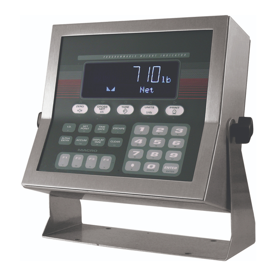
Page 5: Front Panel Display
Figure 1-1. IQ plus 710 Front Panel Front Panel Display Figure 1-1 shows the IQ plus 710 front panel keys and The two-digit annunciator also displays whether the indicator is in numeric entry (NE) or alpha the key functions assigned in normal mode. -
Page 6: Indicator Operations
Indicator Operations 1.3.7 Display or Change Time and Date To display the date, press the key once; TIME/DATE Basic IQ plus 710 operations are summarized below: press TIME/DATE a second time to display the time. 1.3.1 Toggle Gross/Net Mode To set the date, press the key once. -
Page 7: Installation
Cable Connections performed by qualified service personnel only. The IQ plus 710 provides five cord grips for cabling • The supply cord serves as the power disconnect for into the indicator: one for the power cord, four to the IQ plus 710. -
Page 8: Load Cells
C111 D11 D12 DIGITAL OUTPUT BROWN WIRE BLUE WIRE TO LINE FILTER Figure 2-1. IQ plus 710 CPU and Power Supply Board, Rev. 2 2.3.1 Load Cells To attach cable from a load cell or junction box, J1 Pin Function remove connector J1 from the board. -
Page 9: Serial Communications
Figure 2-1 on page 5 and plug are active (on) with low voltage (0 VDC) and can be the module input into connector J5 on the IQ plus 710 driven by TTL or 5V logic without additional board. -
Page 10: Enclosure Reassembly
PC. Figure 2-2. IQ plus 710 Enclosure Backplate Board Removal If you must remove the IQ plus 710 CPU board, use the following procedure: 1. Disconnect power to the indicator. Loosen cord grips and remove backplate as described in Section 2.2 on page 4. -
Page 11: Replacement Parts
Replacement Parts Table 2-5 lists replacement parts for the IQ plus 710, including all parts referenced in Figures 2-3 through 2-7. Number Description (Quantity) Figure 41397 Enclosure, sloped front (1) Figure 2-6 on page 12 41401 Enclosure, flat front (1) - Page 12 Number Description (Quantity) Figure — 42104 7-position connectors for J1, J4, and J12 (3) Figure 2-1 on page 5 — 46420 10-position connectors for J7 and J8 (2) — 45484 160 mA TR5 subminiature fuses (2), 115 VAC F1 and F2 in Figure 2-1 on page 5 45107 80 mA TR5 subminiature fuses (2), 230 VAC The following parts apply only to units using the Rev 1 CPU board with cable interface board...
- Page 13 POWER CORD CABLE TIE 37/4X TO BACKPLATE GROUND STUD TO CPU BOARD P2 8/6X/D Figure 2-4. Enclosure and Line Filter Assembly IQ plus 710 Installation Manual...
- Page 14 40/3X/C 5/6X/A 38/4X SLOPED FRONT MODELS ONLY TO JUMPER JP4 Figure 2-5. Enclosure and CPU Board Assembly Installation...
- Page 15 3/13X/B 44/3X Figure 2-6. Bezel Assembly 29/4X 39/4X 27/2X 25/2X Figure 2-7. Tilt Stand Assembly IQ plus 710 Installation Manual...
-
Page 16: Configuration
Configuration Methods mode. The IQ plus 710 indicator can be configured by using 4. Start the Revolution program. the front panel keys to navigate through a series of Figure 3-1 shows an example of one of the Revolution configuration menus or by sending commands or... -
Page 17: Front Panel Configuration
Front Panel Configuration The IQ plus 710 indicator can be configured using a series of menus accessed through the indicator front panel when the indicator is in setup mode. Table 3-1 summarizes the functions of each of the main menus. -
Page 18: Menu Structures And Parameter Descriptions
Menu Structures and Parameter Descriptions The following sections provide graphic representations of the IQ plus 710 menu structures. In the actual menu structure, the settings you choose under each parameter are arranged horizontally. To save page space, menu choices are shown in vertical columns. The factory default setting appears at the top of each column. Parameters shown surrounded by a dotted-line box only appear under the special circumstances explained under each box. -
Page 19: Configuration Menu
100% FS+9D DIGFLTR DFSENS DFTHRH PWRUPMD TAREFN 8OUT NONE BOTH DELAY 16OUT NOTARE 16RT 32OUT PBTARE 32RT 10DD 64OUT KEYED 20DD 64RT 128OUT 128RT 2OUT 50DD 256RT 4OUT 100DD 200DD 250DD Figure 3-4. Configuration Menu IQ plus 710 Installation Manual... - Page 20 CONFIG Menu Parameter Choices Description Level 2 submenus GRADS 10000 Specifies the number of full scale graduations. The value entered must be in the range number 1–100000 and should be consistent with legal requirements and environmental limits on system resolution. To calculate GRADS, use the formula, GRADS = Capacity / Display Divisions.
- Page 21 Enables or disables push-button and keyed tares. Possible values are: NOTARE BOTH: Both push-button and keyed tares are enabled PBTARE NOTARE: No tare allowed (gross mode only) KEYED PBTARE: Push-button tares enabled KEYED: Keyed tare enabled Table 3-2. Configuration Menu Parameters (Continued) IQ plus 710 Installation Manual...
-
Page 22: Format Menu
3.2.2 Format Menu CONFIG XXXXXXX FORMAT CALIBR SERIAL PROGRM XXXXXXX PFORMT SETPNTS XXXXXXX DIG IN XXXXXXX ALGOUT VERS PRIMAR SECNDR DECFMT DSPRATE DECPNT DSPDIV UNITS DECPNT DSPDIV UNITS MULT 250MS COMMA 500MS 750MS 8888888 888888.8 0.453592 8888880 number 1SEC 8888888 8888880 8888800 1500MS... - Page 23 See Section 10.6 on page 67 for a list of multipliers. keyboard To toggle between primary and secondary units, press the UNITS key. Table 3-3. Format Menu Parameters (Continued) IQ plus 710 Installation Manual...
-
Page 24: Calibration Menu
3.2.3 Calibration Menu See Section 4.0 on page 33 for calibration procedures. CONFIG XXXXXXX FORMAT CALIBR SERIAL PROGRM XXXXXXX PFORMT SETPNTS XXXXXXX DIGIN XXXXXXX ALGOUT VERS WZERO WVAL WSPAN WLIN REZERO *CALIB* CALIB* *CALIB* Display and edit Display and edit Press Enter to Display and edit test weight value... -
Page 25: Serial Menu
3.2.4 Serial Menu See Section 10.3 on page 64 for information about IQ plus 710 serial data formats. CONFIG FORMAT XXXXXXX CALIBR SERIAL PROGRM XXXXXXX SETPNTS XXXXXXX DIG IN XXXXXXX ALGOUT VERS PFORMT PRINT PRNDEST BAUD BITS TERMIN EOLDLY BAUD... - Page 26 SERIAL Menu Parameter Choices Description Level 3 Submenus EDP Port BAUD 9600 Baud rate. Selects the transmission speed for the EDP port. 19200 1200 2400 4800 BITS 8NONE Selects number of data bits and parity of data transmitted from the EDP port. 7EVEN 7ODD TERMIN...
-
Page 27: Program Menu
Allows selection of time format and separator character. See Level 3 submenu parameter TIMESEP descriptions. Use the TIME/DATE key or the ST EDP command to set the time. See Section 5.0 on page 37 for information about using the EDP commands. Table 3-6. Program Menu Parameters IQ plus 710 Installation Manual... - Page 28 PROGRM Menu Parameter Choices Description CONSTUP Specifies the initial consecutive number value used when the indicator is reset. Value specified number must be in the range 0–9 999 999. TARE100 Specifies the truck mode used. If selected, the indicator switches from normal mode to the MODE1 selected truck mode.
-
Page 29: Print Format Menu
Display and edit active character and Decrement ASCII value Increment ASCII value ASCII value of active character of active character Enter numeric ASCII character value Press ENTER or to save value Figure 3-9. Print Format Menu IQ plus 710 Installation Manual... -
Page 30: Setpoints Menu
3.2.7 Setpoints Menu See Section 8.0 on page 51 for more information about configuring and using setpoints. CONFIG FORMAT CALIBR SERIAL PROGRM PFORMT SETPNTS DIG IN XXXXXXX ALGOUT VERS SETPT1 SETPT2 SETPT3 SETPT4 SETPT5 SETPT6 SETPT7 SETPT8 Same as SETPT1 BATCHNG SPNAMES …... - Page 31 AUTO allows batch sequences to repeat continuously. SPNAMES NAME1–NAME16 Allows specification of up to 16 setpoint names. Names can be assigned to GROSSSP, NETSP, –RELSP, DELAY, and WAITSS setpoints. Table 3-7. Setpoint Menu Parameters IQ plus 710 Installation Manual...
- Page 32 SETPNTS Menu Parameter Choices Description Level 3 submenus GROSSSP VALUE Configure GROSSSP, NETSP, and –RELSP setpoints. See Level 4 parameter NETSP PSHTARE descriptions. –RELSP PSHPRNT TRIP BANDVAL HYSTER ALARM PSHACCM PREACT PREVAL BATCH ACCESS NAME DIGOUT RELNUM PAUSE PSHTARE Configure PAUSE, DELAY, and WAITSS setpoints. See Level 4 parameter DELAY PSHPRNT descriptions.
- Page 33 TIMER and CONCUR setpoint types: Specifies the ending setpoint number. Do not specify the number of the TIMER or CONCUR setpoint itself. The TIMER or CONCUR setpoint stops monitoring when the ending setpoint begins. Table 3-7. Setpoint Menu Parameters IQ plus 710 Installation Manual...
-
Page 34: Digital Input Menu
3.2.8 Digital Input Menu FORMAT CONFIG CALIBR SERIAL PROGRM PFORMT SETPNTS DIG IN ALGOUT VERS XXXXXXX XXXXXXX XXXXXXX DIGIN1 DIGIN2 DIGIN3 DIGIN8 • • • KEY7 DSPTAR Same as DIGIN1 ZERO IDKEY KEY8 NT/GRS KEY9 TARE KEYDP UNITS KEY0 PRINT ENTER ACCUM KEY1... -
Page 35: Analog Output Menu
Version menu: when selected, the indicator displays the installed software version number. CONFIG FORMAT XXXXXXX CALIBR SERIAL PROGRM PFORMT XXXXXXX XXXXXXX DIG IN ALGOUT VERS SETPNTS Software version Figure 3-16. Version Menu IQ plus 710 Installation Manual... -
Page 36: Calibration
Calibration ™ The IQ plus 710 can be calibrated using the front panel, EDP commands, or the Revolution configuration utility. Each method consists of the following steps: • Zero calibration • Entering the test weight value • Span calibration •... -
Page 37: Edp Command Calibration
WVAL=nnnnnn<CR> 7. Send the KUPARROW or KEXIT EDP command to exit setup mode. 4. Send the WSPAN EDP command to calibrate span. The indicator displays while *CAL* calibration is in progress. IQ plus 710 Installation Manual... -
Page 38: Revolution Calibration
Revolution Calibration ™ To calibrate the indicator using Revolution, the 4. Enter the Value of Test Weight to be used for span calibration then click indicator EDP port must be connected to a PC running the Revolution configuration utility. 5. The Zero Calibration dialog box prompts you to remove all weight from the scale. -
Page 39: More About Calibration
IQ plus 710 can be 140385, the span coefficient is calculated as follows: calibrated using a calculated span coefficient. The Span_coefficient = (21000 * 22.875 mV) + 140385... -
Page 40: Edp Commands
EDP Commands The IQ plus 710 indicator can be controlled by a Command Function personal computer or remote keyboard connected to KSEC Go to secondary units (pseudo key) the indicator EDP port. Control is provided by a set of EDP commands that can simulate front panel key... -
Page 41: Reporting Commands
List all parameter values This command is equivalent to using the DEFAULT function in TEST mode. See Section 10.8 on page 69 VERSION Write IQ plus 710 software version for more information about test mode. All load NOTE: Write current displayed weight with units c e l l c a l i b r a t i o n s e t t i n g s a r e l o s t w h e n t h e identifier. - Page 42 Command Description Values SEC.DECPNT Secondary units decimal 8.888888, 88.88888, 888.8888, 8888.888, 88888.88, 888888.8, position 8888888, 8888880, 8888800 SEC.DSPDIV Secondary units display divisions 1D, 2D, 5D SEC.UNITS Secondary units LB, KG, G, OZ, TN, T, GN, TROYOZ, TROYLB, LT, NONE SEC.MULT Secondary units multiplier 0.00000–99999.99 DECFMT...
- Page 43 See Section 9.0 on page 55 for information about macro PROMPT#60 programming MACRO1.K01– Set MACRO1 keystroke MACRO1.K30 MACRO2.K01– Set MACRO2 keystroke MACRO2.K30 MACRO3.K01– Set MACRO3 keystroke MACRO3.K30 MACRO4.K01– Set MACRO4 keystroke MACRO4.K30 Table 5-7. PROGRM EDP Commands IQ plus 710 Installation Manual...
- Page 44 Command Description Values SETPOINT Setpoint number 1–8 KIND Setpoint kind OFF, GROSSSP, NETSP, –RELSP, PAUSE, DELAY, WAITSS, TIMER, CONCUR VALUE Setpoint value number PSHTARE Push tare OFF, ON PSHPRINT Push print OFF, ON, WAITSS PSHACCM Push accumulate OFF, ON, ONQUIET TRIP Trip HIGHER, LOWER, INBAND, OUTBAND...
-
Page 45: Normal Mode Commands
Transmit net weight in non-displayed units Transmit tare weight in non-displayed units Query system error conditions nnnnn nnnnn See Section 10.1 on page 62 for detailed information about the XE command response format. Table 5-13. Normal Mode EDP Commands IQ plus 710 Installation Manual... -
Page 46: Batching Control Commands
5.1.6 Batching Control Commands The commands listed below provide batching control through the EDP port. BATSTART If the BATRUN digital input is on or not assigned, the BATSTART command can be used to start the batch program. BATRESET Stops the program and resets the batch program to the first batch step. BATPAUSE Stops the batch program at the current step. -
Page 47: Saving And Transferring Data
Table 5-15. ASCII Translation Table for BATSTATUS Data Saving and Transferring Data 5.2.2 Downloading Configuration Data from PC to Connecting a personal computer to the IQ plus 710 Indicator EDP port allows you to save indicator configuration Configuration data saved on a PC or floppy disk can data to the PC or to download configuration data from... -
Page 48: Print Formatting
Print Formatting Commands Table 6-1 lists commands you can use to format the IQ plus 710 print formats. Commands included in the format strings must be enclosed between < and > delimiters. Any characters outside of the delimiters are printed as text on the ticket. -
Page 49: Default Ticket Formats
Default Ticket Formats Table 6-2 shows the default print formats for the IQ plus 710 and lists the conditions under which each print format is used. The HDRFMT format is used to specify header information that can be used by the other ticket formats. -
Page 50: Customizing Print Formats
ENTER . For shown as blanks. The IQ plus 710 can send or receive example, to check the current configuration of the any ASCII character; the character printed depends on GFMT format, type GFMT and press . - Page 51 Decrement ASCII value Increment ASCII value ASCII value of active character of active character Enter numeric ASCII character value Press ENTER or to save value Figure 6-2. PFORMT Menu, Showing Alphanumeric Character Entry Procedure IQ plus 710 Installation Manual...
-
Page 52: Truck Modes
Truck Modes The truck in/out modes are used to handle multiple allow you to manually enter the tare Keyed tares truck ID numbers and tare weights. Six truck modes weight using the numeric keypad and the TARE key. combine stored ID, keyed tare, and value swapping Keyed tares are available in Modes 1, 3, and 5. -
Page 53: Modes 1 And 2
(TRWOUT format). If value swapping is enabled (modes 3 and 4), the lower weight is always printed as the tare weight. ID. NO. 304812 GROSS 100000. LB TARE 15000. LB RECALLED 85000. LB 08/04/1998 10:55 AM IQ plus 710 Installation Manual... -
Page 54: Setpoints
Setpoints The IQ plus 710 indicator provides eight programmable setpoints for control of both indicator and external equipment functions. Setpoints are configured to trip based on specified conditions; tripping the setpoint can be used to request indicator functions (print, tare, accumulate) or to change the state of a digital output controlling external equipment. - Page 55 START setpoint becomes the current batch step and remains active until a timer expires. The indicator START and END parameters specify the start and end setpoints. The timer value is specified in tenths of a second on the VALUE parameter. Table 8-1. Setpoint Kinds IQ plus 710 Installation Manual...
-
Page 56: Batching Examples
Batching Examples Setpoint 5 is a short (.2-second) delay used to provide an end point for a timer setpoint (setpoint 6). 8.2.1 Example 1 SETPOINT=5 The following example uses seven setpoints to KIND=DELAY dispense material from a container in 100 batches VALUE=2 and to automatically refill the container when its... -
Page 57: Example 2
DIGOUT=2 SETPOINT=3 KIND=WAITSS PSHTARE=ON Setpoint 4 starts the fast fill operation. When the net weight reaches 175 , the setpoint trips and digital output 1 is set off. SETPOINT=4 KIND=NETSP VALUE=175 TRIP=HIGHER BATCH=ON DIGOUT=1 IQ plus 710 Installation Manual... -
Page 58: Macro Programming
Macro Programming Up to four macro sequences can be programmed for the IQ plus 710 indicator. Each macro provides a simulation of up to 30 front panel key presses and can be used to provide single-key, automated operation of a number of processes, including operator identification, prompts, setpoint editing, and batch control. - Page 59 SEC pseudo keys are used to explicitly request primary or secondary units display; DATE the UNITS front panel key toggles between primary and secondary units, CLRCN depending on which is displayed at the time the key is pressed. Table 9-1. MACRO Submenu Parameters (PROGRM Menu) IQ plus 710 Installation Manual...
-
Page 60: Macro Programming Examples
PROGRM Menu Parameter Choices Description PAUSREL MAJORKY The PAUSEREL parameter inserts a pause in the macro sequence that is released MOTION when the specified condition is met. The value specified for this parameter determines when the pause is released: DIGIN1 – DIGIN8 MAJORKY: When any of the five major keys is pressed AZTRACK MOTION: When scale reaches standstill... -
Page 61: Example 2
6. Setpoint 3 is a pause setpoint used to activate KIND=GROSSSP digital output 3. Digital output 3 is wired to VALUE=0 DIGIN2 as a KF2 (press MACRO key F2) TRIP=HIGHER input and starts MACRO 2. BATCH=ON DIGOUT=6 BATCHNG=MANUAL PROMPT#1=ADD BUCKET PROMPT#2=MIX PAINT PROMPT#3=REMOVE BUCKET IQ plus 710 Installation Manual... - Page 62 MACRO 2 MACRO2.STRTBAT=ON MACRO2.K01=PAUSREL.MOTION MACRO2.K01=NAME.2 7. MACRO 2 displays the prompt MIX PAINT the secondary display and waits for scale motion caused by the operator mixing the paint. When scale motion stops, the pause is released and the macro restarts the batch sequence at Setpoint 4.
-
Page 63: Example 3
MACRO1.K09=NAME.2 TRIP=HIGHER MACRO1.K09=TIMEOUT.35 BATCH=ON MACRO1.K10=K2 ACCESS=ON MACRO1.K11=K0 NAME=3 MACRO1.K12=K0 DIGOUT=3 MACRO1.K13=KENTER BATCHNG=MANUAL MACRO1.K14=KSETPOINT MACRO1.K15=PAUSREL.TIMER PROMPT#1=INGRED 1 MACRO1.K15=NAME.3 PROMPT#2=INGRED 2 MACRO1.K15=TIMEOUT.35 PROMPT#3=INGRED 3 MACRO1.K16=K3 PROMPT#4=LOAD PRODUCT A MACRO1.K17=K0 PROMPT#5=LOAD PRODUCT B MACRO1.K18=K0 PROMPT#6=LOAD PRODUCT C MACRO1.K19=KENTER IQ plus 710 Installation Manual... - Page 64 MACRO 2 MACRO 3 MACRO2.K01=PAUSREL.TIMER MACRO3.K01=PAUSREL.TIMER MACRO2.K01=NAME.5 MACRO3.K01=NAME.6 MACRO2.K01=TIMEOUT.100 MACRO3.K01=TIMEOUT.100 MACRO2.K02=KSETPOINT MACRO3.K02=KSETPOINT MACRO2.K03=PAUSREL.TIMER MACRO3.K03=PAUSREL.TIMER MACRO2.K03=NAME.1 MACRO3.K03=NAME.1 MACRO2.K03=TIMEOUT.35 MACRO3.K03=TIMEOUT.35 MACRO2.K04=K1 MACRO3.K04=K1 MACRO2.K05=K5 MACRO3.K05=K1 MACRO2.K06=K0 MACRO3.K06=K0 MACRO2.K07=KENTER MACRO3.K07=KENTER MACRO2.K08=KSETPOINT MACRO3.K08=KSETPOINT MACRO2.K09=PAUSREL.TIMER MACRO3.K09=PAUSREL.TIMER MACRO2.K09=NAME.2 MACRO3.K09=NAME.2 MACRO2.K09=TIMEOUT.35 MACRO3.K09=TIMEOUT.35 MACRO2.K10=K2 MACRO3.K10=K2 MACRO2.K11=K5 MACRO3.K11=K1 MACRO2.K12=K0 MACRO3.K12=K0 MACRO2.K13=KENTER MACRO3.K13=KENTER MACRO2.K14=KSETPOINT...
-
Page 65: Appendix
10.1.2 Using the XE EDP Command The XE EDP command can be used to remotely query the IQ plus 710 for the error conditions shown on the front panel. The XE command returns two 5-digit numbers in the format: xxxxx yyyyy where contains a decimal representation of any existing error conditions as described in Table 10-2. -
Page 66: 10.2 Status Messages
10.2 Status Messages Two EDP commands, P and ZZ, can be used to Error provide status about the indicator. Code Description Binary Value • The P EDP command returns whatever is No error 0000 0000 0000 0000 currently shown in the indicator’s primary A/D physical error 0000 0000 0000 0001 display area. -
Page 67: 10.3 Data Formats
If the initiating device address matches the port If continuous transmission is configured for the EDP address of an IQ plus 710 on the RS-485 network, that or printer port (STREAM parameter on the SERIAL indicator responds. For example, with demand... -
Page 68: 10.4 Ascii Character Chart
10.4 ASCII Character Chart Use the decimal values for ASCII characters listed in Tables 10-3 and 10-4 when specifying print format strings on the IQ plus 710 PFORMT menu. The actual character printed depends on the character mapping used by the output device. - Page 69 ∩ Å » ≡ É ± æ ≥ Æ ≤ ô ⌠ ö ⌡ ò ÷ û ≈ ù ° ÿ • Ö Ü ¢ £ ¥ ƒ Table 10-4. ASCII Character Chart (Part 2) IQ plus 710 Installation Manual...
-
Page 70: Digital Filtering
Set DFTHRH to NONE to turn off the filter override. 10.6 Conversion Factors for Secondary Units The IQ plus 710 has the capability to mathematically parameter. For example, if the primary unit is pounds and the secondary unit is short tons, convert a weight into many different types of units and set the MULT parameter to 0.000500. - Page 71 13.16571 ounces 0.000453 metric tons 0.822857 pounds grams 15.4324 grains troy ounces 0.035274 ounces Table 10-5. Conversion Factors (Continued) 0.002205 pounds 0.001000 kilograms 0.032151 troy ounces 0.002679 troy pounds Table 10-5. Conversion Factors IQ plus 710 Installation Manual...
-
Page 72: 10.7 Analog Output Calibration
10.7 Analog Output Calibration NOTE: The following calibration procedure requires a The analog output must be calibrated after the indicator itself has been configured (Section 3.0) and multimeter to measure voltage or current output from calibrated (Section 4.0). the analog output module. If the option is not already installed, see Section 2.4 on page 6. - Page 73 Press and hold the 1 key to send ASCII “U” characters (decimal 85) from the serial port. ECHO R Echo received characters Press and hold the 2 key to view characters received at serial port. IQ plus 710 display shows lower-case characters as blanks. NOTE: A/D TEST Display A/D test Press and hold the 7 key to display raw count from A/D converter.
-
Page 74: 10.9 Software Upgrade Instructions
10.9 Software Upgrade Instructions 7. For units using the Rev. 1 CPU board with cable interface board, reinstall board using Use the following procedure to replace the IQ plus screws removed in Step 4. 710 EPROM: 8. Position backplate over the enclosure and 1. -
Page 75: Specifications
External loop resistance: 500Ω maximum Measurement Canada Approval AM-5253 Digital Specifications Accuracy Class : 10 000 Microcomputer Hitachi H8/3002 main processor @ III HDn : 20 000 9.8304 MHz Digital Inputs 8 inputs, TTL or switch closure, active-low IQ plus 710 Installation Manual... -
Page 76: Iq Plus 710 Limited Warranty
IQ plus 710 Limited Warranty Rice Lake Weighing Systems (RLWS) warrants that all RLWS equipment and systems properly installed by a Distributor or Original Equipment Manufacturer (OEM) will operate per written specifications as confirmed by the Distributor/OEM and accepted by RLWS. All systems and components are warranted against defects in materials and workmanship for two years.
Need help?
Do you have a question about the IQ plus 710 and is the answer not in the manual?
Questions and answers