Lexmark MS911 Service Manual
Hide thumbs
Also See for MS911:
- Service manual (655 pages) ,
- Technical reference (102 pages) ,
- Quick reference manual (18 pages)

Related Manuals for Lexmark MS911


Summary of Contents for Lexmark MS911
-
Page 1: Finisher Service Manual
MS911, MX91x, and XM91x5 4021-23x, 7421-03x, -23x, -43x Finisher Service Manual • Start diagnostics • Maintenance • Safety and notices • Trademarks • Index June 18, 2014 www.lexmark.com P/N 12G3392... -
Page 2: Product Information
June 18, 2014 The following paragraph does not apply to any country where such provisions are inconsistent with local law: LEXMARK INTERNATIONAL, INC., PROVIDES THIS PUBLICATION “AS IS” WITHOUT WARRANTY OF ANY KIND, EITHER EXPRESS OR IMPLIED, INCLUDING, BUT NOT LIMITED TO, THE IMPLIED WARRANTIES OF MERCHANTABILITY OR FITNESS FOR A PARTICULAR PURPOSE. -
Page 3: Table Of Contents
4021, 7421 Table of contents Product information..................2 Edition notice....................2 Notices and safety information..............21 Safety information...........................21 Preface.......................25 Service manual conventions........................25 General information...................27 Media guidelines.............................27 Paper guidelines ...............................27 Paper characteristics ............................27 Selecting paper.............................28 Selecting preprinted forms and letterhead....................28 Storing paper..............................29 Using specialty media ............................29 Tips on using card stock ..........................29 Tips on using envelopes ..........................29 Tips on using labels ............................30... - Page 4 4021, 7421 Defective flash detected [51]..........................37 Disk full [62] ..............................37 Disk full, scan job canceled ..........................37 Disk must be formatted for use in this device ....................37 Disk near full. Securely clearing disk space.......................38 Empty the hole punch box..........................38 Error reading USB drive. Remove USB......................38 Error reading USB hub.
- Page 5 4021, 7421 Reinstall missing or unresponsive cartridge [31.xy] ..................44 Reinstall missing or unresponsive photoconductor [31.xy]................44 Remove defective disk [61]..........................44 Remove packaging material, [area name] ......................45 Remove packaging material, open door C, remove metal clips, remove all screws from scanner carriage..45 Remove paper from all bins..........................45 Remove paper from bin [x]..........................45 Remove paper from [linked set bin name] .......................45...
- Page 6 4021, 7421 Jams.................................51 Avoiding jams..............................51 Understanding jam messages and locations.....................51 200 paper jams ..............................53 SHPF paper jam service check ........................53 40y paper jams ..............................55 40y paper jam messages ..........................55 [x]‑page jam, press latch to access area G. Leave paper in bin. [40y.xx] .............55 [x]‑page jam, press latch to access area G and clear jammed staples.
- Page 7 4021, 7421 Booklet maker decurl assembly failure service check................129 Motor (booklet maker tamper) failure service check ................131 Motor (booklet maker aligner) failure service check .................133 SHPF elevator bin failure service check......................135 SHPF elevator bin stack height assembly failure service check..............137 SHPF staple unit failure service check ......................140 Punch unit failure service check.........................142 34y errors................................143...
- Page 8 4021, 7421 Diagnostics Menu..........................188 Entering the Diagnostics menu........................188 Reset Separator Roll and Pick Assembly Counter ...................188 Reset Maintenance Counter ...........................188 Reset Fuser Counter ............................188 REGISTRATION ..............................189 SCANNER CALIBRATION ..........................189 Scanner Calibration ............................189 Reset flatbed, ADF front, and ADF back calibration values ................190 PRINT TESTS ..............................190 Print Quality Pages............................190 HARDWARE TESTS ............................191...
- Page 9 4021, 7421 Defaults ..............................198 Printed Page Count.............................198 Permanent Page Count (Perm page count)....................198 Processor ID..............................198 Edge to Edge...............................199 Enable Edge to Edge Copy ..........................199 Parallel Strobe Adjustment (Par 1 Strobe Adj) ...................199 Reset Engine Service Error .........................199 Restore Backup Data ..........................199 Reset Fuser Counter ...........................200 REPORTS .................................200 Menu Settings Page............................200...
- Page 10 4021, 7421 NumPad Job Assist............................206 Format Fax Storage............................206 Fax Storage Location............................206 ADF Edge Erase ...............................206 FB Edge Erase..............................207 Scanner Manual Registration..........................207 Disable Scanner ..............................207 Paper Prompts ..............................207 Envelope Prompts............................207 Action for Prompts............................208 Jobs on Disk ..............................208 Disk Encryption ...............................208 Font Sharpening..............................208 Require Standby..............................208 UI Automation ..............................209 LES Applications ..............................209...
- Page 11 4021, 7421 Horizontal top contact connector ......................216 Horizontal bottom contact connector......................218 Vertical mount contact connector ......................220 Horizontal sliding contact connector ......................222 Low Insertion Force (LIF) connector......................224 Adjustments............................225 Punch holes deviation adjustment .........................225 Bifold skew adjustment ..........................227 Removal procedures..........................228 Staple finisher removals........................229 Staple finisher front cover removal ........................229 Staple finisher right cover removal.........................230 Staple finisher rear cover removal........................230...
- Page 12 4021, 7421 Motor (staple finisher staple unit carriage) removal..................263 Staple finisher staple unit carriage removal ....................263 Staple finisher staple unit carriage gears removal..................264 Staple finisher staple unit carriage wheel removal..................266 Staple finisher FFC removal ..........................267 Staple finisher stack lever actuator removal ....................269 Staple finisher stack clamp solenoid removal....................270 Staple finisher elevator springs removal ......................271 Staple finisher elevator drive gears removal ....................271...
- Page 13 4021, 7421 HPT door removal ............................324 HPT rear cover removal ..........................325 HPT cable removal ............................325 HPT door hinges removal..........................326 Motor (HPT transport) removal ........................327 HPT belts and gears removal ..........................329 HPT transport rollers removal ........................329 Staple, hole punch finisher removals....................331 SHPF top bin extender removal ........................331 SHPF elevator bin removal..........................331 SHPF paddles removal ............................332...
- Page 14 4021, 7421 SHPF controller board removal........................364 Punch unit removal............................365 Sensor (hole punch box full) removal ......................366 SHPF staple unit assembly removal ........................367 SHPF staple unit position sensors removal.....................369 SHPF staple unit drive belt and gear removal....................370 Motor (SHPF staple unit carriage) removal ....................371 SHPF staple unit removal..........................372 SHPF staple unit carriage removal ........................374 SHPF elevator bottom rear gear removal .......................375...
- Page 15 4021, 7421 SHPF booklet maker lower pre-feed guide removal..................422 SHPF booklet maker upper pre‑feed guide removal ..................423 SHPF diverter feed guide removal ........................425 SHPF diverter feed roller removal ........................426 SHPF elevator bin stack limit actuator removal....................429 SHPF elevator bin stack limit switch removal ....................432 SHPF top bin removal .............................433 SHPF top bin exit roller removal ........................434 SHPF compiler feed roller release cam removal.....................436...
- Page 16 4021, 7421 Motor (booklet maker transport) removal .....................478 Motor (booklet maker decurl) removal ......................479 Transport and decurl motor bracket removal ....................479 Bifold roller springs removal...........................480 Booklet maker transport gear and belt removal ....................481 Booklet maker transport roller removal ......................482 Booklet maker decurl gears removal ......................483 Sensor (booklet maker decurl) removal ......................484 Booklet maker decurl guide removal......................485 Motor (bifold guide) removal .........................486...
- Page 17 4021, 7421 Booklet maker tamper tray removal ......................527 Sensor (booklet maker tamper home) removal .....................530 Bifold guide idler gears removal ........................530 Component locations................533 Exterior locations..........................533 Configured model ............................533 Maintenance....................535 Inspection guide............................535 Lubrication specification........................535 Parts catalog....................536 Legend..............................536 Assembly 1: Staple finisher—Frame......................537 Assembly 2: Staple finisher—Covers.....................539 Assembly 3: Staple finisher—Transport section 1.................541 Assembly 4: Staple finisher—Transport section 2.................543...
- Page 18 4021, 7421 Assembly 25: SHPF—Transport section 4....................587 Assembly 26: SHPF—Elevator bin section 1..................589 Assembly 27: SHPF—Elevator bin section 2..................591 Assembly 28: SHPF—Staple unit assembly....................593 Assembly 29: SHPF—Compiler section 1....................595 Assembly 30: SHPF—Compiler section 2....................597 Assembly 31: SHPF—Compiler section 3....................599 Assembly 32: SHPF—Punch unit 1......................601 Assembly 33: SHPF—Punch unit 2......................603 Assembly 34: Booklet maker—Covers....................605 Assembly 35: Booklet maker—Electronics....................607...
- Page 19 4021, 7421 Staple finisher feed and exit section.......................634 Staple finisher compiler section ........................636 Staple finisher bin section..........................642 Horizontal paper transport (HPT) operation..................644 Staple, hole punch finisher (SHPF) operation..................646 SHPF sections..............................646 SHPF top bin exit and elevator bin exit sections.....................646 SHPF punch unit operation ..........................651 SHPF compiler section operation........................653 SHPF compiler section feed........................653 SHPF compiler section paper alignment ....................658...
- Page 20 4021, 7421 Table of contents...
-
Page 21: Notices And Safety Information
4021, 7421 Notices and safety information Safety information Safety information • The safety of this product is based on testing and approvals of the original design and specific components. The manufacturer is not responsible for safety in the event of use of unauthorized replacement parts. •... - Page 22 4021, 7421 Sicherheitshinweise • Die Sicherheit dieses Produkts basiert auf Tests und Zulassungen des ursprünglichen Modells und bestimmter Bauteile. Bei Verwendung nicht genehmigter Ersatzteile wird vom Hersteller keine Verantwortung oder Haftung für die Sicherheit übernommen. • Die Wartungsinformationen für dieses Produkt sind ausschließlich für die Verwendung durch einen Wartungsfachmann bestimmt.
- Page 23 4021, 7421 • El risc de xoc elèctric i de danys personals pot augmentar durant el procés de desmuntatge i de servei d’aquest producte. El personal professional ha d’estar-ne assabentat i prendre les mesures convenients. ATENCIÓ La bateria de liti d'aquest producte no ha estat dissenyada perquè es substitueixi. Hi ha perill d’explosió si no es substitueix correctament la bateria de liti.
- Page 24 4021, 7421...
-
Page 25: Preface
4021, 7421 Preface This manual contains maintenance procedures for service personnel. It is divided into the following chapters: • General information contains a general description of the printer. Special tools and test equipment are discussed. • Diagnostic information contains diagnostic aids you can use to isolate failing FRUs. These diagnostic aids include error code tables, symptom tables, and service checks. - Page 26 4021, 7421...
-
Page 27: General Information
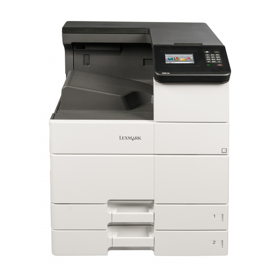
4021, 7421 General information The Lexmark MS911 and MX91x are network‑capable, multifunction laser printers that print monochrome print jobs. The printers are available in the following models: Printer model Configurations Machine type/model MS911 Mono laser SFP, Networking, Duplex print, Duplex scan, 4021-230 4.3‑inch color touch screen... -
Page 28: Selecting Paper
4021, 7421 Curl Curl is the tendency for paper to curl at its edges. Excessive curl can cause paper feeding problems. Curl can occur after the paper passes through the printer, where it is exposed to high temperatures. Storing paper unwrapped in hot, humid, cold, or dry conditions, even in the trays, can contribute to paper curling prior to printing and can cause feeding problems. -
Page 29: Storing Paper
4021, 7421 • Use inks that are not affected by the resin in toner. Inks that are oxidation‑set or oil‑based generally meet these requirements; latex inks might not. • Print samples on preprinted forms and letterheads considered for use before buying large quantities. This determines whether or not the ink in the preprinted form or letterhead will affect print quality. -
Page 30: Tips On Using Labels
• Print samples on labels being considered for use before buying large quantities. • For more information on label printing, characteristics, and design, see the Card Stock & Label Guide on the Lexmark Web site at http://support.lexmark.com. • Use labels designed specifically for laser printers. -
Page 31: Tips On Using Transparencies
4021, 7421 Source Printing Side with the Paper orientation letterhead Multipurpose feeder One‑sided Facedown Load the sheet with the top edge on the left side. Two‑sided Faceup Load the sheet with the top edge on the right side. Tips on using transparencies •... -
Page 32: Supported Paper Types
4021, 7421 Paper size Staple finisher Staple, hole punch Staple, hole punch Booklet finisher finisher bin 1 finisher bin 2 Legal 12 x 18 11 x 17 SRA3 Oficio Folio Statement Universal Paper is supported only if the finisher stacks the paper but does not staple or punch holes in it. Paper is supported only if the finisher stacks or staples the paper but does not punch holes in it. -
Page 33: Tools Required For Service
4021, 7421 Paper type Staple finisher Staple, hole punch finisher Booklet finisher Envelope Rough Envelope Letterhead Preprinted Colored Paper Light Paper Heavy Paper Rough Cotton Custom Type Print on transparencies by batches of only up to 20 to prevent them from sticking together. For more information, see “Tips on using transparencies”... - Page 34 4021, 7421...
-
Page 35: Diagnostic Information
4021, 7421 Diagnostic information CAUTION—SHOCK HAZARD: For personal safety and to prevent damage to the printer, remove the power cord from the electrical outlet before you connect or disconnect any cable, electronic board, or assembly. Disconnect any connections between the printer and the computer or peripherals. CAUTION—POTENTIAL INJURY: The printer weight is greater than 18 kg (40 lb) and requires two or more trained personnel to lift it safely. -
Page 36: Cartridge Nearly Low [88.Xy]
4021, 7421 Cartridge nearly low [88.xy] If necessary, touch Continue on the printer control panel to clear the message and continue printing. Change [paper source] to [custom string] load [orientation] Try one or more of the following: • Load the correct size and type of paper in the tray, specify the paper size and type in the Paper menu on the control panel, and then touch Finished changing paper. -
Page 37: Complex Page, Some Data May Not Have Printed [39]
4021, 7421 Complex page, some data may not have printed [39] Try one or more of the following: • From the control panel, touch Continue to clear the message and continue printing. • Touch Reset active bin to reset the active bin for a linked set of bins. •... -
Page 38: Disk Near Full. Securely Clearing Disk Space
4021, 7421 Note: Formatting deletes all the files stored in the printer hard disk. Disk near full. Securely clearing disk space. Try one or more of the following: • Touch Continue to clear the message and continue printing. • Delete fonts, macros, and other data stored on the printer hard disk. •... -
Page 39: Fax Station Name Not Set Up. Contact System Administrator
4021, 7421 Fax Station Name not set up. Contact system administrator. Try either of the following: • From the printer control panel, touch Continue to clear the message. • Complete the Analog Fax setup. If the message appears again after completing the setup, then contact your system support person. -
Page 40: Insufficient Memory To Collate Job [37]
4021, 7421 Insufficient memory to collate job [37] Try one or more of the following: • From the printer control panel, touch Continue to print the part of the job already stored and begin collating the rest of the print job. •... -
Page 41: Load [Paper Source] With [Paper Size] [Paper Orientation]
4021, 7421 Load [paper source] with [paper size] [paper orientation] Try one or more of the following: • Load the tray or feeder with the correct size of paper, and then touch Finished loading paper on the control panel. • Touch Reset active bin to reset the active bin for a linked set of bins. -
Page 42: Load Multipurpose Feeder With [Paper Type] [Paper Size] [Paper Orientation]
Cancel the print job. [x] maintenance kit very low [80.xy] You may need to replace the maintenance kit very soon. For more information, go to the Lexmark support Web site at http://support.lexmark.com or contact customer support, and then report the message. -
Page 43: Memory Full, Cannot Print Faxes
Turn off the printer, wait for about 10 seconds, and then turn the printer back on. • Update the network firmware in the printer or print server. For more information, visit the Lexmark support Web site at http://support.lexmark.com. Not enough free space in flash memory for resources [52] Try one or more of the following: •... -
Page 44: Parallel Port [X] Disabled [56]
Printer had to restart. Last job may be incomplete. From the printer control panel, touch Continue to clear the message and continue printing. For more information, visit http://support.lexmark.com or contact customer support. Reinstall missing or unresponsive cartridge [31.xy] Try one or more of the following: •... -
Page 45: Remove Packaging Material, [Area Name]
4021, 7421 Remove packaging material, [area name] Remove any remaining packaging material from the specified location. Remove packaging material, open door C, remove metal clips, remove all screws from scanner carriage Open door C and the scanner cover, and then remove any remaining packaging material. Note: Make sure door C does not hit any cable attached to the printer. -
Page 46: Replace Cartridge, Printer Region Mismatch [42.Xy]
Touch Restart job to restart the scan job with the same settings from the previous scan job. Replace [x] maintenance kit, 0 estimated pages remain [80.xy] The printer is scheduled for maintenance. For more information, go to the Lexmark support Web site at http://support.lexmark.com or contact your service representative, and then report the message. -
Page 47: Replace Missing Waste Toner Bottle [82.Xy]
Guide. Note: If you do not have a replacement cartridge, then see the “Ordering supplies” section of the User’s Guide or visit www.lexmark.com. Replace unsupported photoconductor [32.xy] Remove the photoconductor unit, and then install a supported one to clear the message and continue printing. -
Page 48: Scanner Disabled By Admin [840.01]
Remove the jammed paper from the scanner. Scanner maintenance required, use ADF Kit [80] The printer is scheduled for maintenance. For more information, go to the Lexmark support Web site at http://support.lexmark.com or contact your service representative, and then report the message. -
Page 49: Standard Network Software Error [54]
• Turn off the printer, and then turn it back on. • Update the network firmware in the printer or print server. For more information, visit the Lexmark support Web site at http://support.lexmark.com or contact customer support, and then report the message. -
Page 50: Tray [X] Paper Size Unsupported
4021, 7421 Remove the extra trays. Connect the power cord to a properly grounded electrical outlet. Turn the printer back on. Tray [x] paper size unsupported Replace with a supported paper size. Unformatted flash detected [53] Try one or more of the following: •... -
Page 51: Jams
4021, 7421 Jams Avoiding jams Load paper properly • Make sure paper lies flat in the tray. • Do not remove a tray while the printer is printing. • Do not load a tray while the printer is printing. Load it before printing, or wait for a prompt to load it. •... - Page 52 4021, 7421 • When Jam Recovery is set to On or Auto, the printer reprints jammed pages. However, the Auto setting reprints jammed pages only if adequate printer memory is available. Area name Automatic document feeder (ADF) Door C Door D Door F Trays Door H...
-
Page 53: 200 Paper Jams
4021, 7421 Area name Control panel message What to do Doors C and F [x]‑page jam, slide the 3000‑sheet tray and Pull the 3000‑sheet tray, and then remove open door F. [24y.xx] the jammed paper from the side of the tray. Open door F, and then remove the jammed paper. - Page 54 4021, 7421 Action Step 4 Go to step 7. Go to step 5. Test the sensors along the paper path. Enter the Diagnostics menu, and then navigate to: SENSOR TESTS > Staple and Hole Punch Finisher Sensor Tests > select the sensor Toggle the sensor.
-
Page 55: 40Y Paper Jams
4021, 7421 40y paper jams 40y paper jam messages Error code Description Action 400.93 The sensor (staple finisher paper feed) did not detect “Staple finisher paper feed jam service check” the paper from the printer. on page 400.95 Paper remains detected at the sensor (staple finisher paper feed) during a job. - Page 56 4021, 7421 Press the latch and slide the staple finisher to the left, and then remove the jammed paper. Notes: • Make sure that all paper fragments are removed. • If necessary, turn spinner wheel G1 downward to feed jammed paper into the finisher bin, and then remove the paper.
- Page 57 4021, 7421 Slide the finisher back into place. Open door C, and then remove the jammed paper. CAUTION—HOT SURFACE: The inside of the printer might be hot. To reduce the risk of injury from a hot component, allow the surface to cool before touching it. Notes: •...
-
Page 58: [X]-Page Jam, Press Latch To Access Area G And Clear Jammed Staples. Leave Paper In Bin. [402.93]
4021, 7421 [x]‑page jam, press latch to access area G and clear jammed staples. Leave paper in bin. [402.93] Remove all paper from the staple finisher bin. Press the latch on the staple finisher, and then slide the finisher to the left. Remove the staple cartridge holder. - Page 59 4021, 7421 Use the metal tab to lift the staple guard, and then remove any loose staples. Press the staple guard down until it clicks into place. Press the staples against the metal bracket. Note: If the staples are at the rear of the cartridge, then shake the cartridge downward to bring the staples near the metal bracket.
- Page 60 4021, 7421 Push the cartridge holder into the finisher until the holder clicks into place. Slide the finisher back into place. Diagnostic information...
-
Page 61: Staple Finisher Paper Feed Jam Service Check
4021, 7421 Staple finisher paper feed jam service check Action Step 1 Go to step 2. The problem is solved. Remove any debris from the paper path. Reseat the interface cable that is plugged into the printer. Reset the printer. Does the problem remain? Step 2 Go to step 4. - Page 62 4021, 7421 Action Step 6 Go to step 7. The problem is solved. Replace the sensor. See “Sensor (staple finisher paper feed) removal” on page 258. Does the problem remain? Step 7 Go to step 8. The problem is solved. Reseat the cables CN101 and CN111 on the staple finisher controller board.
-
Page 63: 42Y Paper Jams
4021, 7421 Action Step 11 Go to step 12. The problem is solved. Reseat the interface cable on the staple finisher controller board and printer controller board Reseat the junction connector on the cable. Check the cable for damage, and replace if necessary. See “Staple finisher interface cable removal”... -
Page 64: [X]-Page Jam, Open Doors G, H, And J And Clear Jammed Paper. Leave Paper In Bin. [4Yy.xx]
4021, 7421 Error code Description Action 425.95 The paper remains detected at the SHPF compiler “SHPF elevator bin movement service check” during a job. on page 173. 426.93 The sensor (booklet maker transport) did not detect “Booklet maker feed jam service check” on the paper. - Page 65 4021, 7421 Open door J, and then lift handle J1 to its upright position. Open door H. Remove the jammed paper from any of the following locations: Note: Make sure that all paper fragments are removed. • Door J Diagnostic information...
- Page 66 4021, 7421 Note: If there is a jammed paper between the finisher bins, then remove the paper. • Areas H1 and H2 • Areas H3 and H4 Diagnostic information...
-
Page 67: [X]-Page Jam, Open Door H And Rotate Knob H6 Clockwise. Leave Paper In Bin. [426.Xx-428.Xx]
4021, 7421 • Area H6 Close Door H. Open door C, and then remove the jammed paper. Note: Make sure that door C does not hit any cable attached to the printer. Notes: • Make sure that all paper fragments are removed. •... - Page 68 4021, 7421 Open door J, and then lift handle J1. Open door H. Remove the jammed paper from any of the following locations: Note: Make sure that all paper fragments are removed. Diagnostic information...
- Page 69 4021, 7421 • Door J Note: If there is a jammed paper between the finisher bins, then remove the paper. • Areas H1 and H2 Diagnostic information...
- Page 70 4021, 7421 • Areas H3 and H4 • Area H6 Using handle H5, pull out the booklet maker. Remove the jammed paper from any of the following locations: Note: Make sure that all paper fragments are removed. Diagnostic information...
- Page 71 4021, 7421 • Area H8 • Area H9 Diagnostic information...
- Page 72 4021, 7421 • Area H10 Push the booklet maker back into place. Close door H. Open door C, and then remove the jammed paper. CAUTION—HOT SURFACE: The inside of the printer might be hot. To reduce the risk of injury from a hot component, allow the surface to cool before touching it.
-
Page 73: Hpt Feed Jam Service Check
4021, 7421 HPT feed jam service check Action Step 1 Go to step 2. The problem is solved. Remove any debris from the paper path. Reseat the interface cable that is plugged into the SHPF. Reset the printer. Does the problem remain? Step 2 Go to step 3. - Page 74 4021, 7421 Action Step 7 Go to step 8. The problem is solved. Make sure that the sensor is properly installed. Make sure that the sensor is free of debris or dust. Reseat the cable on the sensor. Check the cable for damage, and replace if necessary. See “HPT cable removal”...
-
Page 75: Booklet Maker Transport Section Paper Jam Service Check
4021, 7421 Action Step 13 Go to step 14. The problem is solved. Reseat the interface cable on the HPT and reseat the cable J6 on the SHPF controller board. Reseat the junction connectors on the cable. Make sure that the cable does not block the path of moving parts. Check the cable for damage, and replace if necessary. - Page 76 4021, 7421 Action Step 2 Go to step 3. The problem is solved. Make sure that the booklet maker transport sensor actuator is properly installed. Check the actuator for damage, and replace if necessary. See “Sensor (booklet maker transport) removal” on page 467.
- Page 77 4021, 7421 Action Step 8 Go to step 9. The problem is solved. Make sure that the transport belt and gear are properly installed. Check the belt and gear for wear or damage, and replace if necessary. “Booklet maker transport gear and belt removal” on page 481.
- Page 78 4021, 7421 Action Step 14 Go to step 15. Go to step 16. Make sure that the sensor (booklet maker decurl) is properly installed. Make sure that the sensor is free of debris or dust. Reseat the cable on the sensor. Check the cable for damage, and replace if necessary.
-
Page 79: Booklet Maker Feed Jam Service Check
4021, 7421 Action Step 20 Contact the next level The problem is solved. of support. Replace the controller board. See “Booklet maker controller board removal” on page 462. Does the problem remain? Booklet maker feed jam service check Action Step 1 Go to step 2. - Page 80 4021, 7421 Action Step 5 Go to step 6. The problem is solved. Remove the rear cover and top inner cover. Bypass the front door switch Test the motor (SHPF feed) and motor (SHPF transport). Enter the Diagnostics menu, and then navigate to: Motor Tests >...
- Page 81 4021, 7421 Action Step 10 Go to step 11. Go to step 12. Make sure that the sensor (booklet maker transport) is properly installed. Make sure that the sensor is free of debris or dust. Reseat the cable on the sensor. Check the cable for damage, and replace if necessary.
- Page 82 4021, 7421 Action Step 16 Go to step 17. The problem is solved. Make sure that the transport roller, transport idler rollers, and springs are properly installed. Make sure that the rollers are free of dust or debris. Check the parts for wear or damage, and replace if necessary. See “Booklet maker transport roller removal”...
-
Page 83: Bifold Exit Jam Service Check
4021, 7421 Bifold exit jam service check Action Step 1 Go to step 2. The problem is solved. Remove any debris from the paper path. Reseat the interface cable that is plugged into the SHPF. Reset the printer. Does the problem remain? Step 2 Go to step 4. - Page 84 4021, 7421 Action Step 7 Go to step 8. The problem is solved. Replace the sensor. See “Sensor (booklet maker fold exit) removal” on page 515. Does the problem remain? Step 8 Go to step 9. The problem is solved. Make sure that the trifold diverter is properly installed.
- Page 85 4021, 7421 Action Step 13 Go to step 14. The problem is solved. Make sure that the bifold rollers are free of debris or dust Make sure that the rollers are properly installed. Check the rollers for wear or damage, and replace if necessary. See“Booklet maker—Fold section 1”...
-
Page 86: Shpf Transport Paper Jam Service Check
4021, 7421 Action Step 19 Go to step 20. The problem is solved. Reseat the booklet maker interface cable on the booklet maker controller board and SHPF controller board. Reseat the junction connector on the cable. Check the cable for damage, and replace if necessary. Does the problem remain? Step 20 Go to step 21. - Page 87 4021, 7421 Action Step 3 Go to step 4. The problem is solved. Reseat the cable on the motors. Make sure that the motor is properly installed. Check the motors and cables for damage, and replace if necessary. “Motor (SHPF feed) removal” on page 356 “Motor (SHPF transport) removal”...
- Page 88 4021, 7421 Action Step 9 Go to step 10. The problem is solved. Rotate the two knobs on the SHPF, and check the entrance roller and top bin exit roller for proper rotation: Check the ball bearings for wear or damage, and replace if necessary. “SHPF—Transport section 3”...
-
Page 89: Shpf Top Bin Exit Jam Service Check
4021, 7421 SHPF top bin exit jam service check Action Step 1 Go to step 2. The problem is solved. Remove any debris from the paper path. Reseat the interface cable that is plugged into the printer. Reset the printer. Does the problem remain? Step 2 Go to step 3. - Page 90 4021, 7421 Action Step 7 Go to step 9. Go to step 8. Remove the top inner and rear covers. Bypass the front door switch Test the motor (SHPF feed) and motor (SHPF transport). Enter the Diagnostics menu, and then navigate to: Motor Tests >...
-
Page 91: Shpf Compiler Feed Jam Service Check
4021, 7421 Action Step 12 Go to step 13. The problem is solved. Check the diverter, diverter lever, and diverter spring for wear or damage, and replace if necessary. See “SHPF—Transport section 4” on page 587. Check the diverter cam for wear or damage, and replace if necessary. “SHPF diverter cam removal”... - Page 92 4021, 7421 Action Step 3 Go to step 4. The problem is solved. Reseat the cable J9 on the SHPF controller board. If applicable, reseat the junction connectors on the cable. Make sure that the cable is not in the path of moving parts. Check the cable for damage, and replace if necessary.
- Page 93 4021, 7421 Action Step 8 Go to step 9. The problem is solved. Rotate the two knobs on the SHPF, and check the diverter feed roller and compiler feed roller for proper rotation. Make sure that the rollers are free of debris or dust. Check the rollers and ball bearings for wear or damage, and replace if necessary.
-
Page 94: Shpf Booklet Gate Jam Service Check
4021, 7421 Action Step 13 Go to step 14. The problem is solved. Reseat the interface cable on the SHPF controller board and printer controller board. Reseat the junction connector on the cable. Check the cable for damage, and replace if necessary. Does the problem remain? Step 14 Go to step 15. - Page 95 4021, 7421 Action Step 4 Go to step 5. The problem is solved. Replace the sensor. See “SHPF booklet maker upper pre‑feed guide removal” on page 423. Does the problem remain? Step 5 Go to step 6. The problem is solved. Make sure that the booklet gate jam access door and SHPF jam access door are properly installed.
-
Page 96: Booklet Maker Tamper Paper Jam Service Check
4021, 7421 Action Step 9 Go to step 10. The problem is solved. Make sure that the belts and gears connected to the motors are properly installed. Check the belts and gears for wear or damage, and replace if necessary. See “SHPF—Transport section 2”... - Page 97 4021, 7421 Action Step 2 Go to step 5. Go to step 3. Test the sensor (booklet maker tamper paper present). Enter the Diagnostics menu, and then navigate to: SENSOR TESTS > Hole Punch Booklet Finisher Sensor Tests > Tamper paper present Toggle the sensor.
-
Page 98: 430 Jams
4021, 7421 Action Step 8 Contact the next level The problem is solved. of support. Replace the controller board. See “Booklet maker controller board removal” on page 462. Does the problem remain? 430 jams 430 jam messages Error code Description Action The booklet maker staple unit jammed. - Page 99 4021, 7421 Action Step 2 Go to step 3. The problem is solved. Enter the Diagnostics menu, and then navigate to: PRINTER SETUP > Reset Engine Service Error Note: Perform this step every time a service error occurs. Does the problem remain? Step 3 Go to step 4.
- Page 100 4021, 7421 Action Step 8 Go to step 11. Go to step 9. Test the sensor. Enter the Diagnostics menu, and then navigate to: SENSOR TESTS > Staple Finisher Sensor Tests > Tamper home, front Move the tamper to the sensor. Does the sensor status change while toggling the sensor? Step 9 Go to step 10.
-
Page 101: Motor (Staple Finisher Rear Tamper) Failure Service Check
4021, 7421 Motor (staple finisher rear tamper) failure service check Action Step 1 Go to step 2. The problem is solved. Remove any debris from the paper path. Reseat the interface cable that is plugged into the printer. Reset the printer. Does the problem remain? Step 2 Go to step 3. - Page 102 4021, 7421 Action Step 7 Go to step 8. Go to step 9. Make sure that the sensor (staple finisher rear tamper home) is properly installed. Make sure that the sensor is free of debris or dust. Reseat the cable on the sensor. Check the cable for damage, and replace if necessary.
-
Page 103: Staple Finisher Staple Unit Failure Service Check
4021, 7421 Action Step 13 Contact the next level The problem is solved. of support. Replace the controller board. See “Staple finisher controller board removal” on page 244. Does the problem remain? Staple finisher staple unit failure service check Action Step 1 Go to step 2. - Page 104 4021, 7421 Action Step 6 Go to step 7. The problem is solved. Make sure that the staple unit holder is properly installed. Check the holder for damage, and replace if necessary. See “Staple finisher staple unit removal” on page 260.
- Page 105 4021, 7421 Action Step 12 Go to step 13. The problem is solved. Check the staple finisher interface board for damage, and replace if necessary. See “Staple finisher interface board removal” on page 262. Does the problem remain? Step 13 Go to step 14.
-
Page 106: Motor (Staple Finisher Elevator) Failure Service Check
4021, 7421 Motor (staple finisher elevator) failure service check Action Step 1 Go to step 2. The problem is solved. Make sure that the bin is properly installed. Does the problem remain? Step 2 Go to step 3. The problem is solved. Enter the Diagnostics menu, and then navigate to: Printer setup >... - Page 107 4021, 7421 Action Step 7 Go to step 9. Go to step 8. Test the motor (staple finisher elevator). Enter the Diagnostics menu, and then navigate to: MOTOR TESTS > Staple Finisher Motor Tests > Elevator Check if the bin is properly moving. Is it properly moving? Step 8 Go to step 9.
-
Page 108: 32Y Errors
4021, 7421 Action Step 13 Go to step 14. The problem is solved. Test the sensor. Enter the Diagnostics menu, and then navigate to: SENSOR TESTS > Staple Finisher > Elevator bin stack height or Elevator bin level Toggle the sensor. Does the sensor status change while toggling the sensor? Step 14 Go to step 15. -
Page 109: Shpf Paper Feed Failure Service Check
4021, 7421 Error code Description Action 325.07 The motor (SHPF aligner) failed. “Motor (SHPF aligner) failure service check” on page 116. 326.07 The motor (SHPF front tamper) failed. “Motor (SHPF front tamper) failure service check” on page 119. 327.07 The motor (SHPF rear tamper) failed. “Motor (SHPF rear tamper) failure service check”... - Page 110 4021, 7421 Action Step 4 Go to step 5. The problem is solved. Reseat the cable on the motor. Make sure that the motor is properly installed. Check the motor and cable for damage, and replace if necessary. See “Motor (SHPF feed) removal” on page 356.
-
Page 111: Motor (Shpf Compiler Feed Roller Release) Failure Service Check
4021, 7421 Action Step 10 Go to step 11. The problem is solved. Make sure that the rollers are free of debris or dust. Check the rollers for wear or damage, and replace if necessary. See “SHPF—Transport section 3” on page 585 “SHPF—Transport section 4”... - Page 112 4021, 7421 Action Step 2 Go to step 3. The problem is solved. Enter the Diagnostics menu, and then navigate to: Printer setup > Reset engine service error Note: Perform this step every time a service error occurs. Does the problem remain? Step 3 Go to step 5.
- Page 113 4021, 7421 Action Step 7 Go to step 9. Go to step 8. Test the sensor. Enter the Diagnostics menu, and then navigate to: SENSOR TESTS > Staple and Hole Punch Finisher Sensor Tests > Receiving roller release Toggle the sensor. Does the sensor status change while toggling the sensor? Step 8 Go to step 9.
-
Page 114: Motor (Shpf Paddle) Failure Service Check
4021, 7421 Action Step 13 Go to step 14. The problem is solved. Reseat all the cables on the SHPF controller board. Reset the printer. Does the problem remain? Step 14 Contact the next level The problem is solved. of support. Replace the controller board. - Page 115 4021, 7421 Action Step 5 Go to step 6. Go to step 8. Make sure that the sensor (SHPF paddle home) is properly installed. Make sure that the sensor is free of debris or dust. Reseat the cable on the sensor. Check the cable for damage, and replace if necessary.
-
Page 116: Motor (Shpf Aligner) Failure Service Check
4021, 7421 Action Step 11 Go to step 12. The problem is solved. Manually rotate the paddle shaft to check for proper movement. Check the shaft bushings for wear or damage, and replace if necessary. “SHPF—Compiler section 2” on page 597. - Page 117 4021, 7421 Action Step 2 Go to step 3. The problem is solved. Enter the Diagnostics menu, and then navigate to: Printer setup > Reset engine service error Note: Perform this step every time a service error occurs. Does the problem remain? Step 3 Go to step 5.
- Page 118 4021, 7421 Action Step 8 Go to step 9. The problem is solved. Make sure that the belts and gears connected to the motor and aligner shaft are properly installed. Check the belts and gears for wear or damage, and replace if necessary.
-
Page 119: Motor (Shpf Front Tamper) Failure Service Check
4021, 7421 Motor (SHPF front tamper) failure service check Action Step 1 Go to step 2. The problem is solved. Remove any debris from the paper path. Reseat the interface cable that is plugged into the printer. Reset the printer. Does the problem remain? Step 2 Go to step 3. - Page 120 4021, 7421 Action Step 6 Go to step 8. Go to step 7. Test the sensor. Enter the Diagnostics menu, and then navigate to: SENSOR TESTS > Staple and Hole Punch Finisher Sensor Tests > Tamper home, front Move the tamper to the sensor. Does the sensor status change while toggling the sensor? Step 7 Go to step 8.
-
Page 121: Motor (Shpf Rear Tamper) Failure Service Check
4021, 7421 Action Step 12 Contact the next level The problem is solved. of support. Replace the controller board. See “SHPF controller board removal” on page 364. Does the problem remain? Motor (SHPF rear tamper) failure service check Action Step 1 Go to step 2. - Page 122 4021, 7421 Action Step 5 Go to step 6. Go to step 7. Make sure that the sensor (SHPF rear tamper home) is properly installed. Make sure that the sensor is free of debris or dust. Reseat the cable on the sensor. Check the cable for damage, and replace if necessary.
-
Page 123: Shpf Pre-Eject Failure Service Check
4021, 7421 Action Step 10 Go to step 11. The problem is solved. Reseat the interface cable on the SHPF controller board and printer controller board. Reseat the junction connector on the cable. Check the cable for damage, and replace if necessary. Does the problem remain? Step 11 Go to step 12. - Page 124 4021, 7421 Action Step 4 Go to step 5. The problem is solved. Reseat the cable on the motor. Make sure that the motor is properly installed. Check the motor and cable for damage, and replace if necessary. See “Motor (SHPF compiler pre-eject) removal” on page 400.
-
Page 125: Shpf Ejector Failure Service Check
4021, 7421 Action Step 10 Go to step 11. The problem is solved. Reseat the cable J12 and J13 on the SHPF controller board. If applicable, reseat the junction connectors on the cables. Make sure that the cables do not block the path of moving parts. Check the cables for damage, and replace if necessary. - Page 126 4021, 7421 Action Step 3 Go to step 4. Go to step 9. Remove the upper left cover. Bypass the door switch. Test the motor (SHPF compiler pre-eject) and motor (SHPF compiler eject). Enter the Diagnostics menu, and then navigate to: MOTOR TESTS >...
- Page 127 4021, 7421 Action Step 7 Go to step 9. Go to step 8. Test the sensors. Enter the Diagnostics menu, and then navigate to: SENSOR TESTS > Staple and Hole Punch Finisher Sensor Tests Toggle the sensor. Does the status of the sensor change after toggling it? Step 8 Go to step 9.
-
Page 128: 33Y Errors
4021, 7421 Action Step 13 Go to step 14. The problem is solved. Reseat the interface cable on the SHPF controller board and printer controller board. Reseat the junction connector on the cable. Check the cable for damage, and replace if necessary. Does the problem remain? Step 14 Go to step 15. -
Page 129: Booklet Maker Decurl Assembly Failure Service Check
4021, 7421 Booklet maker decurl assembly failure service check Action Step 1 Go to step 2. The problem is solved. Reseat the interface cable plugged into the SHPF. Reset the printer. Does the problem remain? Step 2 Go to step 3. The problem is solved. - Page 130 4021, 7421 Action Step 7 Go to step 9. Go to step 8. Remove the front cover. Test the motor (booklet maker decurl). Enter the Diagnostics menu, and then navigate to: Motor Tests > Booklet Maker Motor Test > Decurl Check if the belts, gears, and rollers are properly moving.
-
Page 131: Motor (Booklet Maker Tamper) Failure Service Check
4021, 7421 Action Step 13 Go to step 14. The problem is solved. Reseat all the cables on the booklet maker controller board. Reset the printer. Does the problem remain? Step 14 Contact the next level The problem is solved. of support. - Page 132 4021, 7421 Action Step 5 Go to step 8. Go to step 7. Test the sensor (booklet maker tamper home). Enter the Diagnostics menu, and then navigate to: SENSOR TESTS > Hole Punch Booklet Finisher Sensor Tests > Tamper home Toggle the sensor.
-
Page 133: Motor (Booklet Maker Aligner) Failure Service Check
4021, 7421 Action Step 11 Go to step 12. The problem is solved. Reseat all the cables on the booklet maker controller board. Reset the printer. Does the problem remain? Step 12 Contact the next level The problem is solved. of support. - Page 134 4021, 7421 Action Step 5 Go to step 6. The problem is solved. Replace the sensor. See “Sensor (booklet maker aligner home) removal” on page 495. Does the problem remain? Step 6 Go to step 8. Go to step 7. Test the motor (booklet maker aligner).
-
Page 135: Shpf Elevator Bin Failure Service Check
4021, 7421 Action Step 11 Go to step 12. The problem is solved. Reseat all the cables on the booklet maker controller board. Reset the printer. Does the problem remain? Step 12 Contact the next level The problem is solved. of support. - Page 136 4021, 7421 Action Step 5 Go to step 6. Go to step 7. Make sure that the sensor (SHPF elevator position) is properly installed. Make sure that the sensor is free of debris or dust. Reseat the cable on the sensor. Check the cable for damage, and replace if necessary.
-
Page 137: Shpf Elevator Bin Stack Height Assembly Failure Service Check
4021, 7421 Action Step 11 Go to step 12. The problem is solved. Reseat the cable J9 on the SHPF controller board. If applicable, reseat the junction connectors on the cables. Make sure that the cables do not block the path of moving parts. Check the cables for damage, and replace if necessary. - Page 138 4021, 7421 Action Step 3 Go to step 5. Go to step 4. Remove the rear cover. Bypass the front door switch. Test the motor (SHPF elevator bin stack height). Enter the Diagnostics menu, and then navigate to: Motor Tests > Staple and Hole Punch Finisher > Elevaotr bin stack height Check if the elevator bin stack height fingers are properly moving.
- Page 139 4021, 7421 Action Step 8 Go to step 9. The problem is solved. Make sure that the elevator motor encoder and belt are properly installed. Check the encoder and belt for damage, and replace if necessary. See “Motor (SHPF elevator) removal” on page 359.
-
Page 140: Shpf Staple Unit Failure Service Check
4021, 7421 SHPF staple unit failure service check Action Step 1 Go to step 2. The problem is solved. Remove any debris from the paper path. Reseat the interface cable plugged into the printer. Reset the printer. Does the problem remain? Step 2 Go to step 3. - Page 141 4021, 7421 Action Step 6 Go to step 8. Go to step 7. Test the sensors. Enter the Diagnostics menu, and then navigate to: SENSOR TESTS > Staple and Hole Punch Finisher Sensor Tests > Stapler center or Stapler home Toggle the sensor.
-
Page 142: Punch Unit Failure Service Check
4021, 7421 Action Step 12 Contact the next level The problem is solved. of support. Replace the controller board. See “SHPF controller board removal” on page 364. Does the problem remain? Punch unit failure service check Action Step 1 Go to step 2. The problem is solved. -
Page 143: 34Y Errors
4021, 7421 Action Step 6 Go to step 7. The problem is solved. Replace the punch unit. See “Punch unit removal” on page 365. Does the problem remain? Step 7 Go to step 8. The problem is solved. Reseat the interface cable on the SHPF controller board and printer controller board. -
Page 144: Motor (Bifold Guide) Failure Service Check
4021, 7421 Motor (bifold guide) failure service check Action Step 1 Go to step 2. The problem is solved. Reseat the interface cable that is plugged into the SHPF. Reset the printer. Does the problem remain? Step 2 Go to step 3. The problem is solved. - Page 145 4021, 7421 Action Step 7 Go to step 9. Go to step 8. Test the sensor. Enter the Diagnostics menu, and then navigate to: SENSOR TESTS > Hole Punch Booklet Finisher Sensor Tests > Center fold guide home Toggle the sensor. Does the sensor status change while toggling the sensor? Step 8 Go to step 9.
-
Page 146: Booklet Maker Paddle Assembly Failure Service Check
4021, 7421 Action Step 13 Go to step 14. The problem is solved. Make sure that the bifold rollers are free of dust or debris. Make sure that the rollers are properly installed. Check the rollers for wear or damage, and replace if necessary. See “Booklet maker—Fold section 2”... - Page 147 4021, 7421 Action Step 2 Go to step 3. The problem is solved. Enter the Diagnostics menu, and then navigate to: Printer setup > Reset engine service error Note: Perform this step every time a service error occurs. Does the problem remain? Step 3 Go to step 5.
- Page 148 4021, 7421 Action Step 7 Go to step 9. Go to step 8. Test the sensor. Enter the Diagnostics menu, and then navigate to: SENSOR TESTS > Hole Punch Booklet Finisher Sensor Tests > Paddle home Toggle the sensor. Does the status of the sensor change after toggling it? Step 8 Go to step 9.
-
Page 149: Motor (Trifold Guide) Failure Service Check
4021, 7421 Action Step 13 Go to step 14. The problem is solved. Reseat all the cables on the booklet maker controller board. Reset the printer. Does the problem remain? Step 14 Contact the next level The problem is solved. of support. - Page 150 4021, 7421 Action Step 5 Go to step 6. The problem is solved. Make sure that the trifold gate actuator is properly installed. Check the actuator for damage, and replace if necessary. See “Trifold gate actuator removal” on page 490. Does the problem remain? Step 6 Go to step 7.
-
Page 151: Motor (Bifold Knife) Failure Service Check
4021, 7421 Action Step 11 Go to step 12. The problem is solved. Reseat all the cables on the booklet maker controller board. Reset the printer. Does the problem remain? Step 12 Contact the next level The problem is solved. of support. - Page 152 4021, 7421 Action Step 5 Go to step 6. The problem is solved. Check the bifold knife drive and idler gears for wear or damage, and replace if necessary. See “Booklet maker—Fold section 2” on page 611. Does the problem remain? Step 6 Go to step 9.
-
Page 153: Booklet Maker Staple Unit Failure Service Check
4021, 7421 Action Step 11 Go to step 12. The problem is solved. Reseat the interface cable on the booklet maker controller board and SHPF controller board. Reseat the junction connector on the cable. Check the cable for damage, and replace if necessary. Does the problem remain? Step 12 Go to step 13. -
Page 154: 911 Errors
4021, 7421 Action Step 4 Go to step 5. The problem is solved. Make sure that the staple unit is properly installed. Check the unit for damage, and replace if necessary. See “SHPF staple unit removal” on page 372. Does the problem remain? Step 5 Go to step 6. - Page 155 4021, 7421 Action Step 3 Go to step 4. Go to step 5. Make sure that the sensor (staple finisher upper exit roller) is properly installed. Make sure that the sensor is free of debris or dust. Reseat the cable on the sensor. Check the cable for damage, and replace if necessary.
- Page 156 4021, 7421 Action Step 9 Go to step 10. The problem is solved. Make sure the belts and gears connected to the motor and roller are properly installed. Check the belts and gears for wear or damage, and replace if necessary.
-
Page 157: Symptoms
4021, 7421 Symptoms Staple finisher symptoms Staple finisher symptoms Symptom Action A persistent Close door G message appears. “Staple finisher locks service check” on page 157. “Staple finisher bin stack height assembly A persistent Remove paper from standard failure service check” on page 158. -
Page 158: Staple Finisher Bin Stack Height Assembly Failure Service Check
4021, 7421 Action Step 4 Go to step 5. The problem is solved. Make sure that the release handle and front and rear locks are properly installed. Check the handle and locks for damage, and replace if necessary. See “Staple finisher locks removal” on page 241. - Page 159 4021, 7421 Action Step 3 Go to step 4. The problem is solved. Make sure that the bin stack height solenoid is properly installed. Check the solenoid for damage, and replace if necessary. See “Staple finisher bin stack height solenoid removal” on page 235.
- Page 160 4021, 7421 Action Step 9 Go to step 10. The problem is solved. Make sure that the bin is level. Check the bin for damage, and replace if necessary. Does the problem remain? Step 10 Go to step 12. Go to step 11. Test the motor (staple finisher exit) and motor (staple finisher upper exit).
-
Page 161: Staple Finisher Stapling Failure Service Check
4021, 7421 Action Step 15 Go to step 16. The problem is solved. Reseat the interface cable on the staple finisher controller board and printer. Reseat the junction connector on the cable. Check the cable for damage, and replace if necessary. Does the problem remain? Step 16 Go to step 17. - Page 162 4021, 7421 Action Step 4 Go to step 5. The problem is solved. Make sure that the aligner belts and gears are properly installed. Check the belts and gears for wear or damage. Replace if necessary. “Staple finisher—Aligner section” on page 551.
- Page 163 4021, 7421 Action Step 10 Go to step 11. The problem is solved. Make sure that the staple unit holder is properly installed. Check the holder for damage, and replace if necessary. See “Staple finisher staple unit removal” on page 260.
-
Page 164: Shpf Symptoms
4021, 7421 SHPF symptoms SHPF symptoms Symptom Action “SHPF elevator bin movement service check” A persistent Bin 2 full message appears. on page 173. A persistent Close door G message appears. “HPT door service check” on page 164. “SHPF front door service check” on page A persistent Close door H message appears. - Page 165 4021, 7421 Action Step 4 Go to step 7. Go to step 5. Test the sensor (HPT door). Enter the Diagnostics menu, and then navigate to: SENSOR TESTS > Staple, Hole Punch Finisher Sensor Tests > HTU door open Toggle the sensor. Does the sensor status change while toggling the sensor? Step 5 Go to step 6.
-
Page 166: Shpf Front Door Service Check
4021, 7421 Action Step 11 Contact the next level The problem is solved. of support. Replace the controller board. See “SHPF controller board removal” on page 364. Does the problem remain? SHPF front door service check Action Step 1 Go to step 2. The problem is solved. -
Page 167: Shpf Top Door Service Check
4021, 7421 Action Step 6 Go to step 7. The problem is solved. Reseat the cable J3 on the SHPF controller board. If applicable, reseat the junction connectors on the cable. Make sure that the cable is not in the path of moving parts. Check the cable for damage, and replace if necessary. - Page 168 4021, 7421 Action Step 4 Go to step 6. Go to step 5. Make sure that the sensor (SHPF top door) is properly installed. Make sure that the sensor is free of debris or dust. Reseat the cable on the sensor. Check the cable for damage, and replace if necessary.
-
Page 169: Hole Punch Box Service Check
4021, 7421 Hole punch box service check Action Step 1 Go to step 2. The problem is solved. Make sure that the hole punch box is properly installed. Reseat the interface cable that is plugged into the printer. Reset the printer. Does the problem remain? Step 2 Go to step 3. -
Page 170: Shpf Top Bin Full Service Check
4021, 7421 Action Step 6 Go to step 7. The problem is solved. Check the motor (punch unit) and punch unit position sensors for damage, and replace the punch unit if necessary. Reseat the punch unit cable. Check the cable for damage, and replace if necessary. - Page 171 4021, 7421 Action Step 2 Go to step 3. Go to step 4. Make sure that the sensor (SHPF top bin full, transmit) and sensor (SHPF top bin full, receive) are properly installed. Make sure that the sensors are free of debris or dust. Reseat the cable on the sensors.
-
Page 172: Shpf Staple Unit Noise Service Check
4021, 7421 SHPF staple unit noise service check Action Step 1 Go to step 2. The problem is solved. Remove any debris from the paper path. Reseat the interface cable that is plugged into the printer. Reset the printer. Does the problem remain? Step 2 Go to step 3. -
Page 173: Shpf Elevator Bin Movement Service Check
4021, 7421 Action Step 6 Go to step 7. The problem is solved. Reseat the cable J11 on the SHPF controller board. If applicable, reseat the junction connectors on the cable. Make sure that the cable does not block the path of moving parts. Check the cable for damage, and replace if necessary. - Page 174 4021, 7421 Action Step 3 Go to step 4. The problem is solved. Reseat the cables J10 and J14 on the SHPF controller board. If applicable, reseat the junction connectors on the cables. Make sure that the cables do not block the path of moving parts. Check the cables for damage, and replace if necessary.
- Page 175 4021, 7421 Action Step 9 Go to step 10. The problem is solved. Reseat the cable on the motor. Make sure that the motor is properly installed. Check the motor and cable for damage, and replace if necessary. See “Motor (SHPF elevator bin stack height) removal” on page 353.
- Page 176 4021, 7421 Action Step 14 Go to step 16. Go to step 15. Remove the rear cover. Bypass the front door switch. Test the motor (SHPF elevator). Enter the Diagnostics menu, and then navigate to: MOTOR TESTS > Staple and Hole Punch Finisher Motor Tests > Elevator Check if the elevator is moving properly.
-
Page 177: Booklet Maker Symptoms
4021, 7421 Action Step 20 Go to step 21. The problem is solved. Make sure that the elevator belt springs, elevator bin front and rear brackets, and elevator belt holders are properly installed. Check the parts for wear or damage, and replace if necessary. Does the problem remain? Step 21 Go to step 22. -
Page 178: Hpbf Bin Service Check
4021, 7421 HPBF bin service check Action Step 1 Go to step 2. The problem is solved. Remove any debris from under the booklet maker aligner jam access cover. Reseat the interface cable that is plugged into the SHPF. Reset the printer. Does the problem remain? Step 2 Go to step 3. -
Page 179: Bifold Edge Alignment Service Check
4021, 7421 Action Step 7 Go to step 8. The problem is solved. Reseat the interface cable on the booklet maker controller board and SHPF controller board. Reseat the junction connector on the cable. Check the cable for damage, and replace if necessary. Does the problem remain? Step 8 Go to step 9. - Page 180 4021, 7421 Action Step 4 Go to step 7. Go to step 5. Test the motor (booklet maker aligner). Enter the Diagnostics menu, and then navigate to: MOTOR TESTS > Booklet Maker Motor Tests > Stopper Check if the belts, gears, and rollers are moving properly. Are they moving properly? Step 5 Go to step 6.
- Page 181 4021, 7421 Action Step 10 Go to step 12. Go to step 11. Make sure that the sensor is properly installed. Make sure that the sensor is free of debris or dust. Reseat the cable on the sensor. Check the cable for damage, and replace if necessary.
- Page 182 4021, 7421 Action Step 16 Go to step 17. The problem is solved. Reseat the cable on the motor. Make sure that the motor is properly installed. Check the motor and cable for damage, and replace if necessary. See “Motor (bifold knife) removal” on page 491.
-
Page 183: Service Menus
4021, 7421 Service menus Understanding the printer control panel Using the control panel Use the Display • View the printer status and messages. • Set up and operate the printer. Home button Go to the home screen. Sleep button Enable Sleep mode or Hibernate mode. The following actions wake the printer from Sleep mode: •... -
Page 184: Understanding The Home Screen
4021, 7421 Indicator light Printer status The printer is off or in Hibernate mode. Blinking green The printer is warming up, processing data, or printing. Solid green The printer is on, but idle. Blinking red The printer requires user intervention. Sleep button light Printer status The printer is off, idle or in Ready state. - Page 185 4021, 7421 Touch Forms and Favorites Quickly find and print frequently used online forms. Menu icon Access the printer menus. Note: The menus are available only when the printer is in Ready state. Bookmarks Create, organize, and save a set of bookmarks (URL) into a tree view of folders and file links. Note: The tree view supports only bookmarks created from this function, and not from any other application.
-
Page 186: Using The Touch-Screen Buttons
4021, 7421 Feature Description Status message bar • Show the current printer status such as Ready or Busy. • Show printer conditions such as Toner Low or Cartridge Low. • Show intervention messages so the printer can continue processing. Printer IP address The IP address of your network printer is located at the upper left corner of the home screen and appears as four sets of numbers separated by periods. -
Page 187: Menus List
4021, 7421 Other touch-screen buttons Touch Accept Save a setting. Cancel • Cancel an action or a selection. • Exit a screen and return to the previous screen without saving changes. Reset Reset values on the screen. Menus list Paper Menu Reports Network/Ports Security... -
Page 188: Diagnostics Menu
4021, 7421 Paper Menu Reports Network/Ports Security Settings Help Manage Shortcuts Option Card Menu General Settings Print All Guides Fax Shortcuts A list of installed DLEs (Download Emulators) appears. Copy Settings Copy Guide E-mail Shortcuts Fax Settings E-mail Guide FTP Shortcuts E‑mail Settings Fax Guide Copy Shortcuts... -
Page 189: Registration
4021, 7421 REGISTRATION This menu allows you to perform the following: Adjust the top and left margin values of the installed trays. View how the change in margin values affect the overall registration of the printer. To set the registration: Print a Quick Test page. -
Page 190: Reset Flatbed, Adf Front, And Adf Back Calibration Values
4021, 7421 To view the result for a flatbed adjustment, do the following: Remove any paper from the ADF. Compare the results to the original, and adjust if necessary. Place a test page on the flatbed and touch Copy Quick Test. Compare the results to the original, and adjust if necessary. -
Page 191: Hardware Tests
4021, 7421 HARDWARE TESTS Panel Test This test verifies the function of the control panel display. Enter the Diagnostics Menu, and then navigate to: Hardware Tests > Panel Test Exit the test. Button Test This test verifies the function of each button on the control panel. Enter the Diagnostics Menu, and then navigate to: HARDWARE TESTS >... -
Page 192: Serial 1 Wrap
4021, 7421 Serial 1 Wrap This test checks the operation of the serial port hardware using a wrap plug. Each signal is tested. If the test fails, then replace the controller board. Disconnect the serial interface cable, and then install the wrap plug. Enter the Diagnostics Menu, and then navigate to: HARDWARE TESTS >... -
Page 193: Top Margin
4021, 7421 Top Margin This setting controls the offset between the placement of the first scan line on both sides of a duplexed sheet. Note: If adjustment is necessary, adjust first the top margin in the Registration menu. You can adjust next the duplex top margin. -
Page 194: Sensor Tests
4021, 7421 SENSOR TESTS PRINTER SENSOR TESTS These tests verify that the printer sensors are working properly. Enter the Diagnostics Menu, and then navigate to: SENSOR TESTS > PRINTER TESTS Select a sensor. Manually toggle the sensor. Note: The sensor status on the screen toggles between Open and Close when the sensor is working properly. 2 x 500‑Sheet Tray Sensor Tests These tests verify that the 2 x 500-sheet tray sensors are working properly. -
Page 195: Staple And Hole Punch Finisher Sensor Tests
4021, 7421 Staple and Hole Punch Finisher Sensor Tests These tests verify that the staple and hole punch finisher sensors are working properly. Remove the tray inserts from tray 1 and tray 2. Enter the Diagnostics Menu, and then navigate to: SENSOR TESTS >... -
Page 196: 2X500-Sheet Tray Motor Tests
4021, 7421 2x500‑Sheet Tray Motor Tests These tests verify that the 2 x 500‑sheet tray motors are working properly. Enter the Diagnostics Menu, and then navigate to: Motor Tests > 2x500‑Sheet Tray Motor Tests Select a motor. Check if the motor runs. 2500‑Sheet Tray Motor Tests These tests verify that the 2500‑sheet tray motors are working properly. -
Page 197: Booklet Maker Motor Tests
4021, 7421 Booklet Maker Motor Tests These tests verify that the booklet maker motors are working properly. Enter the Diagnostics Menu, and then navigate to: Motor Tests > Booklet Maker Motor Tests Select a motor. Check if the motor runs. DEVICE TESTS Quick Disk Test This test performs a non-destructive read/write test on one block per track on the disk. -
Page 198: Printer Setup
4021, 7421 PRINTER SETUP Defaults Warning—Potential Damage: Modifying printer setting defaults restores the NVRAM space to its factory settings. This setting determines whether the printer uses the U.S. or Non-U.S. factory default value for the following settings: Printer default values U.S. -
Page 199: Edge To Edge
4021, 7421 PRINTER SETUP > Processor ID Edge to Edge This setting shifts all four margins to the physical edges of the page. This feature does not work in PPDS emulation. Enter the Diagnostics Menu, and then navigate to: PRINTER SETUP > Edge to Edge Enable Edge to Edge Copy This setting determines whether the printer accepts the ADF or flatbed edge erase value when performing an ADF or flatbed copy. -
Page 200: Reset Fuser Counter
4021, 7421 Restoring backup data when replacing the engine controller board Before removing the old engine controller board, select Engine card to controller card to move the current engine settings into the controller board. After installing the new engine controller board, select Controller card to engine card to move the engine board settings stored on the controller board to the new engine controller board. -
Page 201: Clear Log
4021, 7421 Clear Log This setting clears current information in the EVENT LOG. Enter the Diagnostics Menu, and then navigate to: EVENT LOG > Clear Log Select a setting. Apply the changes. Print Log Summary This setting prints a summary of the printed event logs. Enter the Diagnostics Menu, and then navigate to: EVENT LOG >... -
Page 202: Asic Test
4021, 7421 ASIC Test This setting scans the ASIC memory of the scanner. Enter the Diagnostics Menu, and then navigate to: SCANNER TESTS > ASIC Test Feed Test This test allows for a continuous feed from the ADF or flatbed. Enter the Diagnostics Menu, and then navigate to: SCANNER TESTS >... -
Page 203: Configuration Menu
4021, 7421 This menu appears as a soft button at the bottom right corner of the display. Configuration Menu Entering the Configuration menu Turn off the printer. Press and hold 2 and 6 while turning on the printer. Release the buttons when the splash screen appears. Hole Punch Configuration The values in this setting determine which values appear in the Hole Punch Mode setting and which value is the default. -
Page 204: Reports
4021, 7421 Reports Menu Settings Page This report lists of the Configuration Menu settings and the value of each setting. Enter the Configuration Menu, and then navigate to: Reports > Menu Settings Page Return to the Configuration Menu screen. Event Log This setting prints a report of the detailed events in the print log. -
Page 205: Ppds Emulation
4021, 7421 Apply the changes. PPDS Emulation This setting determines if the printer can recognize and use the PPDS data stream. Enter the Configuration Menu, and then select PPDS Emulation. Select a setting. Apply the changes. Download Emuls This menu appears only if at least one download emulator (DLE) is installed. The default setting is Disable. All download emulators are automatically re‑enabled after two PORs. -
Page 206: Min Copy Memory
4021, 7421 Min Copy Memory This setting determines how much DRAM is allowed to be stored in the priority queue for copy jobs. Note: The values appear only if the amount of installed DRAM is at least twice the amount of the value. Enter the Configuration Menu, and then select Min Copy Memory. -
Page 207: Fb Edge Erase
4021, 7421 FB Edge Erase This setting sets the size of the no‑print area around a flatbed scan job. Enter the Configuration Menu, and then select FB Edge Erase. Select a setting. Apply the changes. Scanner Manual Registration Use this setting to register the flatbed and ADF on the scanner. Perform a registration adjustment whenever the ADF, flatbed, or controller board is replaced. -
Page 208: Action For Prompts
4021, 7421 Action for Prompts This gives you the option to allow the printer to resolve change prompt situations without requiring any user assistance. Enter the Configuration Menu, and then select Action for Prompts. Select a setting. Apply the changes. Jobs on Disk This setting allows you to delete buffered jobs from the printer hard disk. -
Page 209: Ui Automation
Enter the Configuration Menu, and then select UI Automation. Select a setting. Apply the changes. LES Applications This setting allows you to enable the Lexmark Embedded Solutions (LES) applications. Enter the Configuration Menu, and then select LES Applications. Select a setting. Apply the changes. -
Page 210: Usb Speed
4021, 7421 USB Speed This setting determines the throughput of the USB port on the printer. Enter the Configuration Menu, and then select USB Speed. Select a setting. Apply the changes. Automatically Display Error Screens This setting allows the automatic display of existing printer-related messages on the home screen after the printer remains inactive. -
Page 211: Out Of Service Erase
4021, 7421 Enter the Configuration Menu, and then navigate to: Restore Factory Defaults > Erase Hard Disk Select any of the following: • Single Pass Erase overwrites all data and the file system. This wipe is faster but less secure since it is possible to retrieve the deleted data with forensic data‑retrieval techniques. -
Page 212: Entering Safe Mode (Everready Mode)
4021, 7421 Entering Safe Mode (EverReady Mode) This mode enables the printer to temporarily offer minimal print capabilities. Turn off the printer. Press and hold 7 and 6 while turning on the printer. Release the buttons after 10 seconds. Accessing the Network SE Menu This menu contains settings for fine tuning the communication settings for the network interfaces and protocols. -
Page 213: Fax Service Engineer (Se) Menu
4021, 7421 Top level menu Intermediate menu TCP/IP • netstat‑r • arp‑a • Allow SNMP Set • • Meditech Mode • RAW LPR Mode • Gather Debug • Enable Debug Fax Service Engineer (SE) Menu Use this menu for the fax transmission and fax reception service checks. Use this menu as directed by the next level of support. - Page 214 4021, 7421...
-
Page 215: Repair Information
4021, 7421 Repair information Removal precautions CAUTION—SHOCK HAZARD: For personal safety and to prevent damage to the printer, remove the power cord from the electrical outlet before you connect or disconnect any cable, electronic board, or assembly. Disconnect any connections between the printer and the computer or peripherals. Handling ESD‑sensitive parts Many electronic products use parts that are known to be sensitive to electrostatic discharge (ESD). -
Page 216: Horizontal Top Contact Connector
4021, 7421 To avoid damaging the connectors and their cables, observe the following: • Do not insert the cables where the contacts are facing the locking actuator. • Do not insert the cables diagonally into the ZIF socket. • Avoid using a fingernail or sharp object to open the locking actuator. •... - Page 217 4021, 7421 Rotate the locking actuator to the locked position. Notes: • Do not move the cable while locking the actuator. • If the cable moves, open the actuator, reposition the cable, and then close the actuator. Repair information...
-
Page 218: Horizontal Bottom Contact Connector
4021, 7421 Horizontal bottom contact connector This connector uses a flip locking actuator to lock the ribbon cable into the ZIF connector. Warning—Potential Damage: When opening or closing this type of actuator, gently lift the center of the actuator using your finger. Do not use a fingernail or screwdriver to open the actuator to avoid damaging the ribbon cable. Do not close the actuator from its ends. - Page 219 4021, 7421 Inserting the cable Make sure that the actuator is in the open position. Insert the cable below the actuator with the contacts facing downward and away from the locking actuator. Note: Make sure that the cable is installed squarely into the connector to avoid intermittent failures. Repair information...
-
Page 220: Vertical Mount Contact Connector
4021, 7421 Rotate the locking actuator to the locked position. Vertical mount contact connector This connector uses a back flip locking actuator to lock the ribbon cable into the ZIF connector. Warning—Potential Damage: When opening or closing this type of actuator, gently lift the center of the actuator using your finger. - Page 221 4021, 7421 Inserting the cable Make sure that the locking actuator is in the open position. Insert the cable on top of the actuator with the contacts facing away from the locking actuator. Note: Make sure that the cable is installed squarely into the connector to avoid intermittent failures. Rotate the locking actuator to the locked position.
-
Page 222: Horizontal Sliding Contact Connector
4021, 7421 Horizontal sliding contact connector This connector uses a slide locking actuator to lock the ribbon cable into the ZIF connector. Warning—Potential Damage: When opening or closing this type of actuator, gently push or pull the two tabs located on each end of the actuator. Do not close the actuator from the center of the actuator. Do not use a screwdriver to open or close the actuator to avoid damage to the cable or connector. - Page 223 4021, 7421 Inserting the cable Make sure that the locking actuator is in the open position. If you are opening the connector, then pull back the end tabs using equal force to avoid breaking the connector. Insert the cable on top of the actuator with the contacts facing away from the locking actuator. Slide the locking actuator toward the connector to lock the cable.
-
Page 224: Low Insertion Force (Lif) Connector
4021, 7421 Low Insertion Force (LIF) connector Warning—Potential Damage: When installing a cable into an LIF connector, avoid bending the edges of the cables and damaging the contacts on the cables. Inserting the cable Make sure that the contacts of the controller board and connectors are on the same side. Insert the cable. -
Page 225: Adjustments
4021, 7421 Adjustments Punch holes deviation adjustment Perform this procedure when the deviation between the holes is more than 2 mm. Perform a punch job. Fold the paper, and then measure the deviation between the holes. If the deviation is more than 2 mm, then proceed with the rest of the steps. - Page 226 4021, 7421 Open the SHPF top cover, and then loosen the two screws (A). Using the marks (B) on the frame, move the punch unit to adjust its position. Repair information...
-
Page 227: Bifold Skew Adjustment
4021, 7421 Bifold skew adjustment Perform this procedure when: • Reinstalling the booklet maker aligner assembly. • The fold skew exceeds the tolerance of +/‑ 1 mm. Send a bifold print job. Unfold the paper with the ridge facing up. Confirm the skew (A) by measuring the length of edges A1 and A2. -
Page 228: Removal Procedures
4021, 7421 Lift the aligner jam access door, and then loosen the two screws (C). Rotate the aligner assembly depending on the direction of the skew. • Rotate the aligner assembly to the rear. • Rotate the aligner assembly to the front. Removal procedures Keep the following tips in mind as you replace parts: •... -
Page 229: Staple Finisher Removals
4021, 7421 • Unless otherwise stated, reinstall the parts in reverse order of removal. • When reinstalling a part held with several screws, start all screws before the final tightening. Staple finisher removals Staple finisher front cover removal Remove the three screws (A). Remove the screw (B), and then remove the cover. -
Page 230: Staple Finisher Right Cover Removal
4021, 7421 Staple finisher right cover removal Remove the front cover. See “Staple finisher front cover removal” on page 229. Remove the screw (A), and then remove the cover. Staple finisher rear cover removal Remove the three screws (A). Remove the cover. Installation note: Position the metal tab (B) over the cover. -
Page 231: Staple Finisher Top Cover Removal
4021, 7421 Staple finisher top cover removal Remove the front cover. See “Staple finisher front cover removal” on page 229. Remove the rear cover. See “Staple finisher rear cover removal” on page 230. Remove the screw (A). Slide, and then remove the cover. Repair information... -
Page 232: Staple Finisher Exit Guide Removal
4021, 7421 Staple finisher exit guide removal Remove the front cover. See “Staple finisher front cover removal” on page 229. Remove the rear cover. See “Staple finisher rear cover removal” on page 230. Remove the top cover. See “Staple finisher top cover removal” on page 231. -
Page 233: Staple Finisher Left Inner Cover Removal
4021, 7421 Staple finisher left inner cover removal Remove the bin. See “Staple finisher bin removal” on page 232. Remove the two screws (A), and then remove the cover. Staple finisher lower exit roller paddles removal Remove the bin. See “Staple finisher bin removal”... -
Page 234: Staple Finisher Bin Stack Height Assembly Sensors Removal
4021, 7421 Remove the two screws (A). Swing out, and then set aside the assembly. Staple finisher bin stack height assembly sensors removal Remove the bin. See “Staple finisher bin removal” on page 232. Remove the left inner cover. See “Staple finisher left inner cover removal”... -
Page 235: Staple Finisher Bin Stack Height Solenoid Removal
4021, 7421 Disconnect the cable, and then remove the sensor. Part Sensor (staple finisher bin level) Sensor (staple finisher bin stack height) Staple finisher bin stack height solenoid removal Remove the bin. See “Staple finisher bin removal” on page 232. Remove the left inner cover. -
Page 236: Staple Finisher Bin Stack Height Actuator Removal
4021, 7421 Remove the bin stack height assembly. See “Staple finisher bin stack height assembly removal” on page 233. Disconnect the cable (A). Remove the two screws (B), and then remove the solenoid. Staple finisher bin stack height actuator removal Remove the bin. - Page 237 4021, 7421 Remove the clip (A). Remove the spring (B) and the solenoid link (C). Repair information...
-
Page 238: Motor (Staple Finisher Tamper) Removal
4021, 7421 Remove the two screws (D). Remove the bracket to release the link from the actuator, and then remove the actuator. Motor (staple finisher tamper) removal Remove the bin. See “Staple finisher bin removal” on page 232. Remove the left inner cover. See “Staple finisher left inner cover removal”... -
Page 239: Staple Finisher Tamper Sensors Removal
4021, 7421 Part Motor (staple finisher rear tamper) Motor (staple finisher front tamper) Remove the motor. Staple finisher tamper sensors removal Remove the bin. See “Staple finisher bin removal” on page 232. Remove the left inner cover. See “Staple finisher left inner cover removal” on page 233. -
Page 240: Staple Finisher Transport Jam Removal Gears Removal
4021, 7421 Part Sensor (staple finisher rear tamper home) Sensor (staple finisher tamper paper present) Sensor (staple finisher front tamper home) Disconnect the cable from the sensor, and then remove the sensor from the bracket. Staple finisher transport jam removal gears removal Remove the front cover. -
Page 241: Staple Finisher Lock Switch Removal
4021, 7421 Staple finisher lock switch removal Remove the front cover. See “Staple finisher front cover removal” on page 229. Remove the clip (A), and then remove the handle. Disconnect the cable (B). Remove the screw (C), and then remove the switch. Staple finisher locks removal Remove the front cover. - Page 242 4021, 7421 Pry the latch (A), and then remove the rear lock. Remove the clip (B), and then remove the handle. Remove the two springs (C). Repair information...
-
Page 243: Staple Finisher Guide Rails Removal
4021, 7421 Remove the clip (D), and then remove the front lock. Staple finisher guide rails removal Remove the front cover. See “Staple finisher front cover removal” on page 229. Remove the rear cover. See “Staple finisher rear cover removal” on page 230. -
Page 244: Staple Finisher Controller Board Removal
4021, 7421 From the front, remove the screw (B), and then remove the front guide rail. Staple finisher controller board removal Remove the rear cover. See “Staple finisher rear cover removal” on page 230. Disconnect all the cables from the board, and then remove the screw (A). Remove the board. -
Page 245: Staple Finisher Controller Board Holder Removal
4021, 7421 Staple finisher controller board holder removal Remove the rear cover. See “Staple finisher rear cover removal” on page 230. Remove the controller board. See “Staple finisher controller board removal” on page 244. Remove all the cable holders from the controller board holder. Remove the three screws (A), and then remove the controller board holder. - Page 246 4021, 7421 Remove the screw (B), and then remove the cable bracket. Cut the two zip ties (C), and then remove the cable. Repair information...
-
Page 247: Motor (Staple Finisher Transport) Removal
4021, 7421 Installation notes: Plug the two cables into the controller board, and then pass them through the cable guide. Mount the cable bracket on the finisher, and then secure the cable with two zip ties (A). Install the screw (B). Motor (staple finisher transport) removal Remove the rear cover. - Page 248 4021, 7421 Remove the four screws (B), and then remove the bracket. Remove the two screws (C), and then remove the motor. Repair information...
- Page 249 4021, 7421 Installation notes: Install the motor on the bracket. Do not tighten the two screws (A). Install the bracket on the frame, and then tighten the four screws (B). Note: Position the ground wire on top of the bracket. Repair information...
-
Page 250: Motor (Staple Finisher Elevator) Removal
4021, 7421 Tighten the top screw (C), and then tighten the bottom screw (D). Motor (staple finisher elevator) removal Remove the rear cover. See “Staple finisher rear cover removal” on page 230. Disconnect the three cables (A). Remove the two screws (B), and then remove the cable holder. Repair information... -
Page 251: Motor (Staple Finisher Upper Exit) Removal
4021, 7421 Remove the two screws (C), and then remove the motor. Motor (staple finisher upper exit) removal Remove the front cover. See “Staple finisher front cover removal” on page 229. Remove the spring (A), and then disconnect the cable (B). Remove the two screws (C), and then remove the motor. - Page 252 4021, 7421 Remove the two screws (D), and then remove the motor. Installation notes: Install the motor on the plate. Install the motor on the frame, and then install the two screws (A). Do not tighten the screws. Install the spring (B). Repair information...
-
Page 253: Motor (Staple Finisher Exit) Removal
4021, 7421 Tighten the screw (C) near the spring, and then tighten the top screw (D). Connect the motor cable. Motor (staple finisher exit) removal Remove the front cover. See “Staple finisher front cover removal” on page 229. Remove the spring (A), and disconnect the cable (B). Remove the two screws (C), and then remove the motor. -
Page 254: Motor (Staple Finisher Aligner) Removal
4021, 7421 Remove the two screws (D), and then remove the motor. Installation note: See the installation note in “Motor (staple finisher upper exit) removal” on page 251. Motor (staple finisher aligner) removal Remove the front cover. See “Staple finisher front cover removal” on page 229. -
Page 255: Staple Finisher Aligner Belt And Gears Removal
4021, 7421 Staple finisher aligner belt and gears removal Remove the front cover. See “Staple finisher front cover removal” on page 229. Disconnect the cable (A). Remove the four screws (B), and then remove the motor bracket. Remove the belt (C). Remove the clip (D), and then remove the gear. -
Page 256: Sensor (Staple Finisher Upper Exit Roller) Removal
4021, 7421 Remove the gear (E). Sensor (staple finisher upper exit roller) removal Remove the front cover. See “Staple finisher front cover removal” on page 229. Disconnect the cable (A). Remove the screw (B), and then remove the sensor bracket. Remove the sensor from the bracket. -
Page 257: Sensor (Staple Finisher Elevator Home) Removal
4021, 7421 Sensor (staple finisher elevator home) removal Remove the front cover. See “Staple finisher front cover removal” on page 229. Disconnect the cable (A). Remove the screw (B), and then remove the sensor bracket. Remove the sensor from the bracket. Sensor (staple finisher staple unit home) removal Remove the front cover. -
Page 258: Sensor (Staple Finisher Paper Feed) Removal
4021, 7421 Disconnect the cable (B), and then remove the sensor. Sensor (staple finisher paper feed) removal Remove the front cover. See “Staple finisher front cover removal” on page 229. Remove the rear cover. See “Staple finisher rear cover removal” on page 230. - Page 259 4021, 7421 Remove the screw (B), and then remove the ground (C). Flip the sensor holder, and then remove the sensor. Disconnect the cable (D), and then remove the sensor. Repair information...
-
Page 260: Staple Finisher Staple Unit Removal
4021, 7421 Staple finisher staple unit removal Remove the front cover. See “Staple finisher front cover removal” on page 229. Remove the two screws (A), and then remove the holder. Disconnect the two cables (B). Remove the screw (C), and then remove the staple unit. Repair information... -
Page 261: Staple Finisher Staple Unit Carriage Assembly Removal
4021, 7421 Remove the two screws (D), and then remove the plate. Staple finisher staple unit carriage assembly removal Remove the front cover. See “Staple finisher front cover removal” on page 229. Remove the staple unit. See “Staple finisher staple unit removal” on page 260. -
Page 262: Staple Finisher Interface Board Removal
4021, 7421 Disconnect the cable (B), and then remove the assembly. Staple finisher interface board removal Remove the front cover. See “Staple finisher front cover removal” on page 229. Remove the staple unit. See “Staple finisher staple unit removal” on page 260. -
Page 263: Motor (Staple Finisher Staple Unit Carriage) Removal
4021, 7421 Motor (staple finisher staple unit carriage) removal Remove the front cover. See “Staple finisher front cover removal” on page 229. Remove the staple unit. See “Staple finisher staple unit removal” on page 260. Remove the staple unit carriage assembly. See “Staple finisher staple unit carriage assembly removal”... -
Page 264: Staple Finisher Staple Unit Carriage Gears Removal
4021, 7421 Remove the three screws (B), and then remove the card holder and motor. The carriage remains. Staple finisher staple unit carriage gears removal Remove the front cover. See “Staple finisher front cover removal” on page 229. Remove the staple unit. See “Staple finisher staple unit removal”... - Page 265 4021, 7421 Remove the clip (A), and then remove the wheel and gear. Disconnect the cable (B). Remove the two screws (C), and then remove the motor bracket. Repair information...
-
Page 266: Staple Finisher Staple Unit Carriage Wheel Removal
4021, 7421 Remove the clip (D), and then remove the gear. Staple finisher staple unit carriage wheel removal Remove the front cover. See “Staple finisher front cover removal” on page 229. Remove the staple unit. See “Staple finisher staple unit removal” on page 260. -
Page 267: Staple Finisher Ffc Removal
4021, 7421 Staple finisher FFC removal Remove the front cover. See “Staple finisher front cover removal” on page 229. Remove the rear cover. See “Staple finisher rear cover removal” on page 230. Remove the staple unit. See “Staple finisher staple unit removal” on page 260. - Page 268 4021, 7421 Press the latch, and then remove the cable holder. Remove the cable from the holder. Installation notes: Place the cable on a flat surface, with the contacts facing down. Place the plastic film over the cable, and then position the tab under the cable. Align the edge of the film with the blue end.
-
Page 269: Staple Finisher Stack Lever Actuator Removal
4021, 7421 Install the bent end on the cable holder. Thread the two clips through the film. Thread the cable and the film through the rest of the clips. Staple finisher stack lever actuator removal Remove the rear cover. See “Staple finisher rear cover removal”... -
Page 270: Staple Finisher Stack Clamp Solenoid Removal
4021, 7421 Unlatch and then remove the actuator (B). Staple finisher stack clamp solenoid removal Remove the rear cover. See “Staple finisher rear cover removal” on page 230. Remove the controller board. See “Staple finisher controller board removal” on page 244. -
Page 271: Staple Finisher Elevator Springs Removal
4021, 7421 Staple finisher elevator springs removal Remove the front cover. See “Staple finisher front cover removal” on page 229. Remove the rear cover. See “Staple finisher rear cover removal” on page 230. Remove the bin. See “Staple finisher bin removal” on page 232. -
Page 272: Staple Finisher Elevator Belts Removal
4021, 7421 Remove the rear guide rail. See “Staple finisher guide rails removal” on page 243. Remove the motor (staple finisher elevator). See “Motor (staple finisher elevator) removal” on page 250. Remove the six screws (A), and then remove the bracket. Remove the four clips (B), and then remove all the gears from the bracket. - Page 273 4021, 7421 Remove the rear guide rail. See “Staple finisher guide rails removal” on page 243. Remove the motor (staple finisher elevator). See “Motor (staple finisher elevator) removal” on page 250. Remove the elevator drive gears bracket. See “Staple finisher elevator drive gears removal” on page 271.
-
Page 274: Staple Finisher Elevator Gears Removal
4021, 7421 Remove the clip (C), remove the front belt cover, and then remove the belt. Remove the screw (D), and then remove the belt from the bracket. Installation note: To ensure that the front and rear brackets are level, place them at their lowest position before installing the belts on the gears. - Page 275 4021, 7421 Remove the elevator drive gears. See “Staple finisher elevator drive gears removal” on page 271. Remove the elevator belts. See “Staple finisher elevator belts removal” on page 272. Remove the gear (A). Remove the screw (B), and then remove the gear bracket. Remove the two screws (C), and then remove the gear bracket.
- Page 276 4021, 7421 Remove the clip (D), and then remove the gear. Also remove the gear from the other bracket. Repair information...
-
Page 277: Exit Motor Bracket Removal
4021, 7421 Exit motor bracket removal Remove the front cover. See “Staple finisher front cover removal” on page 229. Remove the clip (A), and then remove the handle. Disconnect the six cables (B). Repair information... - Page 278 4021, 7421 Remove the six screws (C). Remove the staple unit carriage home sensor cover, and then disconnect the two cables (D). Remove all the cables from the bracket, and then remove the bracket. Repair information...
-
Page 279: Staple Finisher Exit Guide Lift Cam Removal
4021, 7421 Staple finisher exit guide lift cam removal Remove the front cover. See “Staple finisher front cover removal” on page 229. Remove the rear cover. See “Staple finisher rear cover removal” on page 230. Remove the top cover. See “Staple finisher top cover removal”... -
Page 280: Staple Finisher Upper Exit Roller Drive Gears Removal
4021, 7421 Installation notes: • The upper exit roller assembly must be in the lowermost position. • Align the pointer on the gear with the notch on the frame. Staple finisher upper exit roller drive gears removal Remove the front cover. See “Staple finisher front cover removal”... - Page 281 4021, 7421 Remove the clip (A), and then remove the washer and gear. Remove the pin (B), and then remove the clip and bushing. Repair information...
- Page 282 4021, 7421 Remove the clip (C), and then remove the bushing. Remove the shaft. Remove the two clips (D), and then remove the gear and bushing. Repair information...
-
Page 283: Staple Finisher Exit Roller Drive Belts And Gears Removal
4021, 7421 Remove the plate (E). Staple finisher exit roller drive belts and gears removal Remove the front cover. See “Staple finisher front cover removal” on page 229. Remove the exit motor bracket. See “Exit motor bracket removal” on page 277. -
Page 284: Staple Finisher Exit Roller Solenoid Removal
4021, 7421 Remove the three gears (B), and two belts (C). Remove the two clips (D), and then remove the gears. Staple finisher exit roller solenoid removal Remove the front cover. See “Staple finisher front cover removal” on page 229. Remove the exit motor bracket. -
Page 285: Staple Finisher Upper Exit Actuator Removal
4021, 7421 Remove the screw (B), and then remove the solenoid. Staple finisher upper exit actuator removal Remove the front cover. See “Staple finisher front cover removal” on page 229. Remove the exit motor bracket. See “Exit motor bracket removal” on page 277. -
Page 286: Staple Finisher Exit Roller Gear Removal
4021, 7421 Staple finisher exit roller gear removal Remove the front cover. See “Staple finisher front cover removal” on page 229. Remove the exit motor bracket. See “Exit motor bracket removal” on page 277. Disconnect the spring (A). Unlatch and then remove the gear (B). Staple finisher lower exit roller removal Remove the front cover. -
Page 287: Staple Finisher Upper Guide Removal
4021, 7421 Lower the actuator, and then remove the roller. Remove the lower exit roller paddles. See “Staple finisher lower exit roller paddles removal” on page 233. Staple finisher upper guide removal Remove the front cover. See “Staple finisher front cover removal” on page 229. - Page 288 4021, 7421 Remove the six screws (B). Repair information...
- Page 289 4021, 7421 Remove the clip (C), and then slide the bushing. Remove the guide from the finisher. Remove the screw (D), and then remove the sensor holder. Repair information...
- Page 290 4021, 7421 Pry, and then remove the four rollers (E). Installation note: The springs are color-coded according to their location. Repair information...
-
Page 291: Staple Finisher Lower Guide Removal
4021, 7421 Staple finisher lower guide removal Remove the front cover. See “Staple finisher front cover removal” on page 229. Remove the rear cover. See “Staple finisher rear cover removal” on page 230. Remove the top cover. See “Staple finisher top cover removal” on page 231. -
Page 292: Staple Finisher Staple Unit Rail Removal
4021, 7421 Remove the five screws (B), and then remove the idler rollers. Staple finisher staple unit rail removal Remove the front cover. See “Staple finisher front cover removal” on page 229. Remove the rear cover. See “Staple finisher rear cover removal” on page 230. -
Page 293: Staple Finisher Compiler Feed Roller Guide Removal
4021, 7421 Remove the upper guide. See “Staple finisher upper guide removal” on page 287. Remove the lower guide. See “Staple finisher lower guide removal” on page 291. Remove the three screws (A), and then remove the rail. Staple finisher compiler feed roller guide removal Remove the front cover. - Page 294 4021, 7421 Release the four latches (A), and then remove the guides. Installation note: Position the guides under the flaps (A). Repair information...
-
Page 295: Staple Finisher Aligner Roller Removal
4021, 7421 Staple finisher aligner roller removal Remove the front cover. See “Staple finisher front cover removal” on page 229. Remove the rear cover. See “Staple finisher rear cover removal” on page 230. Remove the top cover. See “Staple finisher top cover removal” on page 231. -
Page 296: Staple Finisher Compiler Feed Roller Shaft Assembly Removal
4021, 7421 Slide, and then swing out to remove the roller. Remove the other roller. Staple finisher compiler feed roller shaft assembly removal Remove the front cover. See “Staple finisher front cover removal” on page 229. Remove the rear cover. See “Staple finisher rear cover removal”... - Page 297 4021, 7421 Remove the clip (A), and then remove the washer and gear. Remove the clip (B), and then remove the bushing. Repair information...
-
Page 298: Staple Finisher Compiler Feed Rollers And Gears Removal
4021, 7421 Remove the clip (C), and then remove the bushing. Remove the clip (D), and then remove the assembly. Staple finisher compiler feed rollers and gears removal Remove the front cover. See “Staple finisher front cover removal” on page 229. - Page 299 4021, 7421 Remove the exit motor bracket. See “Exit motor bracket removal” on page 277. Remove the upper guide. See “Staple finisher upper guide removal” on page 287. Remove the lower guide. See “Staple finisher lower guide removal” on page 291.
-
Page 300: Staple Finisher Stack Lever Removal
4021, 7421 Remove the two compiler feed rollers (D) and the two gears (E). Staple finisher stack lever removal Remove the front cover. See “Staple finisher front cover removal” on page 229. Remove the rear cover. See “Staple finisher rear cover removal” on page 230. -
Page 301: Staple Finisher Transport Roller Removal
4021, 7421 Remove the clip (B), and then slide the lever. Remove the lever, and then remove the pin. Staple finisher transport roller removal Remove the front cover. See “Staple finisher front cover removal” on page 229. Remove the rear cover. See “Staple finisher rear cover removal”... - Page 302 4021, 7421 Remove the two clips (A), and then remove the gears and bushings. Repair information...
-
Page 303: Staple Finisher Aligner Roller Gears Removal
4021, 7421 Remove the clip (B), and then remove the shaft. Staple finisher aligner roller gears removal Remove the front cover. See “Staple finisher front cover removal” on page 229. Remove the rear cover. See “Staple finisher rear cover removal” on page 230. - Page 304 4021, 7421 Remove the clip (A). Remove the clip (B). Dislodge the shaft from the frame. Rotate the shaft until the pins behind the gears are horizontal. Repair information...
-
Page 305: Staple Finisher Upper Exit Roller Assembly Removal
4021, 7421 Remove the two clips (C), and then remove the gears. Staple finisher upper exit roller assembly removal Remove the front cover. See “Staple finisher front cover removal” on page 229. Remove the rear cover. See “Staple finisher rear cover removal” on page 230. -
Page 306: Staple Finisher Eject Guide Removal
4021, 7421 Remove the two clips (A), and then remove the bushings. Remove the assembly. Staple finisher eject guide removal Remove the front cover. See “Staple finisher front cover removal” on page 229. Remove the rear cover. See “Staple finisher rear cover removal” on page 230. -
Page 307: Staple Finisher Eject Cam Removal
4021, 7421 Remove the exit motor bracket. See “Exit motor bracket removal” on page 277. Remove the exit guide lift cam. See “Staple finisher exit guide lift cam removal” on page 279. Remove the upper exit roller drive gear shaft. See “Staple finisher upper exit roller drive gears removal”... -
Page 308: Staple Finisher Upper Exit Roller Removal
4021, 7421 Remove the exit guide lift cam. See “Staple finisher exit guide lift cam removal” on page 279. Remove the upper exit roller drive gear shaft. See “Staple finisher upper exit roller drive gears removal” on page 280. Remove the upper exit actuator. See “Staple finisher upper exit actuator removal”... -
Page 309: Staple Finisher Upper Exit Roller Belts And Gear Removal
4021, 7421 Remove the guide (A), and then remove the clip (B). Move the guide to release the bushing, and then remove the roller (C). Staple finisher upper exit roller belts and gear removal Remove the front cover. See “Staple finisher front cover removal” on page 229. - Page 310 4021, 7421 Remove all the clips and bushings from the left side of the shaft. Separate the shaft. Note: Take note of the original position of the ground and the two concentric springs. Repair information...
-
Page 311: Staple Finisher Tamper And Aligner Assembly Removal
4021, 7421 Remove the three clips (A), and then remove the lever (B). Remove the bushings, and then remove the gear (C) and two belts (D). Staple finisher tamper and aligner assembly removal Remove the front cover. See “Staple finisher front cover removal” on page 229. - Page 312 4021, 7421 Remove the controller board holder. See “Staple finisher controller board holder removal” on page 245. Remove the exit motor bracket. See “Exit motor bracket removal” on page 277. Remove the upper guide. See “Staple finisher upper guide removal” on page 287.
-
Page 313: Staple Finisher Tamper Drive Gears Removal
4021, 7421 Remove the cables (B) from the holder. From the top, remove the aligner. Staple finisher tamper drive gears removal Remove the front cover. See “Staple finisher front cover removal” on page 229. Remove the rear cover. See “Staple finisher rear cover removal” on page 230. - Page 314 4021, 7421 Remove the controller board holder. See “Staple finisher controller board holder removal” on page 245. Remove the exit motor bracket. See “Exit motor bracket removal” on page 277. Remove the upper guide assembly. See “Staple finisher upper guide removal” on page 287.
-
Page 315: Staple Finisher Tamper Racks Removal
4021, 7421 Staple finisher tamper racks removal Remove the front cover. See “Staple finisher front cover removal” on page 229. Remove the rear cover. See “Staple finisher rear cover removal” on page 230. Remove the top cover. See “Staple finisher top cover removal” on page 231. - Page 316 4021, 7421 Pry both sides to remove the tamper. Repeat this step to remove the other tamper plate. Remove the two screws (A). Release the four latches (B), and then remove the tamper tray. Repair information...
- Page 317 4021, 7421 From under the tray, remove the tamper paper present sensor actuator (C). Remove the two screws (D), and then remove the front and rear aligners. Note: The rear aligner has a clear plastic film, while the front aligner has a black plastic film. Swing and then remove the middle aligner.
- Page 318 4021, 7421 Remove the two ground plates (E) from under the front and rear aligners. Slide the carriage, remove the screw (F), and then remove the bracket. Repair information...
- Page 319 4021, 7421 Disconnect the spring (G) from the assembly, and then remove the carriage. Repeat the previous step and this step to remove the other carriage. Move the tamper racks to the outermost position. Remove the screw (H), remove the bracket, and then remove the two racks (J). Repair information...
- Page 320 4021, 7421 Installation notes: Install the front rack at the outermost position. Install the rear rack at the outermost position. Repair information...
-
Page 321: Horizontal Paper Transport Removals
4021, 7421 Horizontal paper transport removals HPT door locks removal Remove the four screws (A). Remove the locks. HPT inner paper guide removal Remove the three screws (A). Remove the guide. Repair information... -
Page 322: Hpt Holding Bracket Removal
4021, 7421 HPT holding bracket removal Remove the two screws (A). Remove the bracket. Sensor (HPT feed) Disconnect the cable (A). Remove the adhesive (B), and then remove the sensor. Repair information... -
Page 323: Hpt Feed Sensor Actuator Removal
4021, 7421 HPT feed sensor actuator removal Pry the actuator (A). Remove the actuator. Sensor (HPT door) removal Disconnect the cable (A). Remove the screw (B), and then remove the sensor. Repair information... -
Page 324: Hpt Right Top Cover Removal
4021, 7421 HPT right top cover removal Remove the two screws (A). Remove the cover. HPT door removal Remove the right top cover. See “HPT right top cover removal” on page 324. Remove the two screws (A), and then remove the hinge. Remove the cover. -
Page 325: Hpt Rear Cover Removal
4021, 7421 HPT rear cover removal Remove the metal screw (A). Remove the two plastic screws (B), and then remove the cover. HPT cable removal Remove the rear cover. See “HPT rear cover removal” on page 325. Disconnect the cable from both ends (A), and then remove the cable. Repair information... -
Page 326: Hpt Door Hinges Removal
4021, 7421 Disconnect the cable from the two sensors (B), and then remove the cable. HPT door hinges removal Remove the two screws (A). Remove the hinge, and then remove the door. Remove the rear cover. See “HPT rear cover removal” on page 325. -
Page 327: Motor (Hpt Transport) Removal
4021, 7421 Remove the two screws (B), and then remove the hinge. From under the door, remove the two screws (C), and then remove the two hinges. Motor (HPT transport) removal Remove the rear cover. See “HPT rear cover removal” on page 325. - Page 328 4021, 7421 Remove the two screws (B), and then set aside the cable guide. Remove the four screws (C), and then remove the motor bracket. Repair information...
-
Page 329: Hpt Belts And Gears Removal
4021, 7421 Remove the two screws (D), and then remove the motor. HPT belts and gears removal Remove the rear cover. See “HPT rear cover removal” on page 325. Remove the motor (HPT transport). See “Motor (HPT transport) removal” on page 327. - Page 330 4021, 7421 Remove the three clips (A). Remove the six screws (B), and then remove the plates. Installation note: Position the ground wire over the plates before installing the screws. Remove the three clips (C), and then remove the bushings. Remove the rollers.
-
Page 331: Staple, Hole Punch Finisher Removals
4021, 7421 Staple, hole punch finisher removals SHPF top bin extender removal Lift the end of the extender. Remove the extender. SHPF elevator bin removal Remove the two screws (A). Remove the bin. Repair information... -
Page 332: Shpf Paddles Removal
4021, 7421 SHPF paddles removal Pull the three paddles (A). Remove the paddles. SHPF elevator bin bracket removal Note: This part is not a FRU. Remove the elevator bin. See “SHPF elevator bin removal” on page 331. Remove the four screws (A), and then remove the bracket. Repair information... -
Page 333: Hpbf Bin Bail Removal
4021, 7421 HPBF bin bail removal Unlatch and then remove the lock. Remove the bail. SHPF lower cover removal Remove the two screws (A). Remove the cover. SHPF caster wheel removal Remove the lower cover. See “SHPF lower cover removal” on page 333. -
Page 334: Shpf Front Door Switch Removal
4021, 7421 Remove the nut, and then remove the wheel. SHPF front door switch removal Open the front door. Remove the two screws (A), and then remove the cover. Repair information... - Page 335 4021, 7421 Disconnect the two cables (B), and then remove the switch from the cover. Repair information...
-
Page 336: Shpf Front Door Removal
4021, 7421 SHPF front door removal Unlatch and then remove the two locks. Remove the door. SHPF top inner cover removal Remove the front door. See “SHPF front door removal” on page 336. Remove the five screws (A). Repair information... -
Page 337: Shpf Diverter Feed Roller Knob Removal
4021, 7421 Unlatch and then remove the knob (B). Remove the cover. SHPF diverter feed roller knob removal Remove the front door. See “SHPF front door removal” on page 336. Remove the top inner cover. See “SHPF top inner cover removal” on page 336. -
Page 338: Shpf Post Cover Removal
4021, 7421 Unlatch and then remove the knob (A). SHPF post cover removal Remove the lower cover. See “SHPF lower cover removal” on page 333. Remove the front door. See “SHPF front door removal” on page 336. Remove the four screws, and then remove the cover. Repair information... -
Page 339: Shpf Rear Cover Removal
4021, 7421 SHPF rear cover removal Remove the eight screws. Remove the cover. SHPF top door removal Remove the front door. See “SHPF front door removal” on page 336. Remove the top inner cover. See “SHPF top inner cover removal” on page 336. -
Page 340: Booklet Gate Jam Access Door Removal
4021, 7421 Remove the screw (A), and then remove the door. Booklet gate jam access door removal Open the front door. Turn the staple carriage knob to move the carriage to the rear. Release the jam access door from the magnetic catch. From the bottom right, remove the clip (A) from the door tab. - Page 341 4021, 7421 Installation notes: Install the bottom door tab on the bottom frame hole. Push the top part of the jam access door to the frame. Align the top door tab with the top frame hole. Close the door. Align the pin on the door with the hole on the frame. Repair information...
-
Page 342: Shpf Jam Access Door Removal
4021, 7421 Reach in from the right side, and then pull down the door. The door tabs should set into the holes. Install the clip. SHPF jam access door removal Remove the rear cover. See “SHPF rear cover removal” on page 339. -
Page 343: Sensor (Shpf Elevator Bin Full) Removal
4021, 7421 Sensor (SHPF elevator bin full) removal From behind the lower left cover, select the FRU. Part SHPF elevator bin full sensor cable SHPF elevator bin full sensor actuator Sensor (SHPF elevator bin full) Remove the FRU. Repair information... -
Page 344: Lower Left Cover Removals
4021, 7421 Lower left cover removals HPBF lower left cover removal Pry one side, and then remove the HPBF bin. Remove the seven screws (A). Swing out the cover. Repair information... - Page 345 4021, 7421 Disconnect the two cables (B), and then remove the cover. Remove the HPBF bin bail. See “HPBF bin bail removal” on page 333. SHPF lower left cover removal From behind the lower left cover, disconnect the cable (A). Repair information...
- Page 346 4021, 7421 Remove the seven screws (B), and then remove the cover. Repair information...
-
Page 347: Hpbf Lower Left Cover Sensors Removals
4021, 7421 HPBF lower left cover sensors removals Remove the HPBF lower left cover. See “Lower left cover removals” on page 344. Remove the FRU. Part HPBF elevator bin full sensor actuator Sensor (HPBF elevator bin full) Sensor (HPBF bin empty, receive) Sensor (HPBF bin empty, transmit) HPBF exit roller cover removal Remove the HPBF lower left cover. -
Page 348: Shpf Upper Left Cover Removal
4021, 7421 Remove the two screws (B), and then remove the cover. SHPF upper left cover removal Remove the elevator bin. See “SHPF elevator bin removal” on page 331. Remove the elevator bin bracket. See “SHPF elevator bin bracket removal” on page 332. -
Page 349: Shpf Upper Left Cover Sensors Removal
4021, 7421 Swing out the cover. Disconnect the two cables (B), and then remove the cover. SHPF upper left cover sensors removal Remove the elevator bin. See “SHPF elevator bin removal” on page 331. Remove the elevator bin bracket. See “SHPF elevator bin bracket removal”... -
Page 350: Shpf Elevator Bin Stack Height Sensor Actuator Removal
4021, 7421 Remove the appropriate sensor. Part Sensor (SHPF elevator bin stack height, receive) Sensor (SHPF elevator bin stack height, transmit) Sensor (SHPF elevator bin front stack height) Sensor (SHPF elevator bin rear stack height) Sensor (SHPF bin lever control) SHPF elevator bin stack height sensor actuator removal Note: Shown is the removal of the front actuator. -
Page 351: Shpf Elevator Bin Stack Height Sensor Actuator Arms And Gears Removal
4021, 7421 Disconnect the link (D). Rotate and then remove the lever. SHPF elevator bin stack height sensor actuator arms and gears removal Remove the elevator bin. See “SHPF elevator bin removal” on page 331. Remove the elevator bin bracket. See “SHPF elevator bin bracket removal”... -
Page 352: Shpf Elevator Bin Stack Height Drive Gear Removal
4021, 7421 Remove the two screws (A), and then remove the shaft. Disconnect the two links (B), and then remove the actuator arms and gears. SHPF elevator bin stack height drive gear removal Remove the elevator bin. See “SHPF elevator bin removal” on page 331. -
Page 353: Motor (Shpf Elevator Bin Stack Height) Removal
4021, 7421 Remove the clip (A), and then remove the gear. Motor (SHPF elevator bin stack height) removal Remove the elevator bin. See “SHPF elevator bin removal” on page 331. Remove the elevator bin bracket. See “SHPF elevator bin bracket removal” on page 332. -
Page 354: Motor (Shpf Front Tamper) Removal
4021, 7421 Remove the two screws (B), and then remove the motor. Motor (SHPF front tamper) removal Remove the front door. See “SHPF front door removal” on page 336. Remove the top inner cover. See “SHPF top inner cover removal” on page 336. -
Page 355: Sensor (Shpf Front Tamper Home) Removal
4021, 7421 Remove the two screws (C), and then remove the motor. Sensor (SHPF front tamper home) removal Remove the front door. See “SHPF front door removal” on page 336. Remove the top inner cover. See “SHPF top inner cover removal” on page 336. -
Page 356: Motor (Shpf Feed) Removal
4021, 7421 Motor (SHPF feed) removal Remove the rear cover. See “SHPF rear cover removal” on page 339. Disconnect the cable (A). Remove the two screws (B), and then remove the motor bracket. Remove the two screws (C), and then remove the motor. Motor (SHPF transport) removal Remove the rear cover. -
Page 357: Motor (Shpf Rear Tamper) Removal
4021, 7421 Remove the two screws (B), and then remove the motor bracket. Remove the two screws (C), and then remove the motor. Motor (SHPF rear tamper) removal Remove the rear cover. See “SHPF rear cover removal” on page 339. Disconnect the cable (A). - Page 358 4021, 7421 Remove the two screws (B), and then remove the motor bracket. Remove the two screws (C), and then remove the motor. Repair information...
-
Page 359: Sensor (Shpf Rear Tamper Home) Removal
4021, 7421 Sensor (SHPF rear tamper home) removal Remove the rear cover. See “SHPF rear cover removal” on page 339. Release the latch (A), and then remove the sensor. Disconnect the cable from the sensor. Motor (SHPF elevator) removal Remove the rear cover. See “SHPF rear cover removal”... - Page 360 4021, 7421 Remove the four screws (B), and then remove the motor bracket. Disconnect the cable (C). Repair information...
-
Page 361: Sensor (Shpf Elevator Position) Removal
4021, 7421 Remove the two screws (D), and then remove the motor. Sensor (SHPF elevator position) removal Remove the rear cover. See “SHPF rear cover removal” on page 339. Remove the elevator motor bracket. See “Motor (SHPF elevator) removal” on page 359. -
Page 362: Shpf Elevator Drive Assembly Removal
4021, 7421 SHPF elevator drive assembly removal Remove the rear cover. See “SHPF rear cover removal” on page 339. Remove the motor (SHPF elevator). See “Motor (SHPF elevator) removal” on page 359. Remove the sensor (SHPF elevator position). See “Sensor (SHPF elevator position) removal” on page 361. -
Page 363: Sensor (Shpf Top Bin Full) Removal
4021, 7421 Installation notes: Install the spring, and then install the pin. Install the gears with the teeth (A) facing each other. Sensor (SHPF top bin full) removal Remove the rear cover. See “SHPF rear cover removal” on page 339. Remove the elevator motor bracket. -
Page 364: Shpf Paddle Cam And Compiler Guide Lever Removal
4021, 7421 SHPF paddle cam and compiler guide lever removal Remove the rear cover. See “SHPF rear cover removal” on page 339. Remove the appropriate FRU. Part SHPF paddle cam SHPF compiler guide lever SHPF controller board removal Remove the rear cover. See “SHPF rear cover removal”... -
Page 365: Punch Unit Removal
4021, 7421 Remove the four screws (A), and then remove the board. Punch unit removal Remove the rear cover. See “SHPF rear cover removal” on page 339. Disconnect the cable (A) from the controller board. Remove the screw (B), and then pull out the punch unit. Repair information... -
Page 366: Sensor (Hole Punch Box Full) Removal
4021, 7421 Sensor (hole punch box full) removal Remove the rear cover. See “SHPF rear cover removal” on page 339. Remove the punch unit. See “Punch unit removal” on page 365. Disconnect the cable (A), and then remove the sensor. Remove the screw (B), remove the plastic sheet, and then remove the sensor. -
Page 367: Shpf Staple Unit Assembly Removal
4021, 7421 SHPF staple unit assembly removal Remove the front door. See “SHPF front door removal” on page 336. Remove the top inner cover. See “SHPF top inner cover removal” on page 336. Remove the two screws (A). Disconnect the two cables (B), and then remove the two screws (C). Repair information... - Page 368 4021, 7421 Turn the knob (D) to move the staple unit under the front aligner. Push the assembly to the left, and then partially pull it out. Repair information...
-
Page 369: Shpf Staple Unit Position Sensors Removal
4021, 7421 Lift the assembly until the cables on the bottom clear the finisher frame, and then remove the assembly. SHPF staple unit position sensors removal Remove the front door. See “SHPF front door removal” on page 336. Remove the top inner cover. See “SHPF top inner cover removal”... -
Page 370: Shpf Staple Unit Drive Belt And Gear Removal
4021, 7421 SHPF staple unit drive belt and gear removal Remove the front door. See “SHPF front door removal” on page 336. Remove the top inner cover. See “SHPF top inner cover removal” on page 336. Remove the staple unit assembly. See “SHPF staple unit assembly removal”... -
Page 371: Motor (Shpf Staple Unit Carriage) Removal
4021, 7421 Motor (SHPF staple unit carriage) removal Remove the front door. See “SHPF front door removal” on page 336. Remove the top inner cover. See “SHPF top inner cover removal” on page 336. Remove the staple unit assembly. See “SHPF staple unit assembly removal”... -
Page 372: Shpf Staple Unit Removal
4021, 7421 SHPF staple unit removal Remove the front door. See “SHPF front door removal” on page 336. Remove the top inner cover. See “SHPF top inner cover removal” on page 336. Remove the staple unit assembly. See “SHPF staple unit assembly removal” on page 367. - Page 373 4021, 7421 Disconnect the two cables (C), and then remove the carriage. Remove the two screws (D). Rotate, and then remove the staple unit. Repair information...
-
Page 374: Shpf Staple Unit Carriage Removal
4021, 7421 SHPF staple unit carriage removal Remove the front door. See “SHPF front door removal” on page 336. Remove the top inner cover. See “SHPF top inner cover removal” on page 336. Remove the staple unit assembly. See “SHPF staple unit assembly removal” on page 367. -
Page 375: Shpf Elevator Bottom Rear Gear Removal
4021, 7421 Unlatch and then remove the cable holder (C). Flip the carriage, and then remove the belt from the holder (D). Remove the carriage. SHPF elevator bottom rear gear removal Remove the elevator bin. See “SHPF elevator bin removal” on page 331. -
Page 376: Shpf Elevator Bottom Front Gear Removal
4021, 7421 Remove the screw (A), and then remove the bracket. Remove the gear from the bracket. SHPF elevator bottom front gear removal Remove the elevator bin. See “SHPF elevator bin removal” on page 331. Remove the elevator bin bracket. See “SHPF elevator bin bracket removal”... -
Page 377: Shpf Elevator Belts Removals
4021, 7421 Remove the screw (A), and then remove the bracket. Remove the gear from the bracket. SHPF elevator belts removals Elevator rear belt removal Remove the elevator bin. See “SHPF elevator bin removal” on page 331. Remove the elevator bin bracket. See “SHPF elevator bin bracket removal”... - Page 378 4021, 7421 Remove the screw (A), and then remove the belt from the holder. Elevator front belt removal Remove the elevator bin. See “SHPF elevator bin removal” on page 331. Remove the elevator bin bracket. See “SHPF elevator bin bracket removal” on page 332.
- Page 379 4021, 7421 Remove the screw (A), and then remove the belt from the holder. Installation notes: Make sure the motor (SHPF elevator) is not yet installed. Install the belts on the elevator bottom gears. Set both elevator plates on the stoppers (A). Mount the bottom elevator gear brackets (B) on the finisher frame.
- Page 380 4021, 7421 Install the belts (C) on the elevator top gears. Verify if both elevator plates are aligned. Tighten the two screws (D) on the brackets, and then install the motor (SHPF elevator). Repair information...
-
Page 381: Shpf Elevator Top Rear Gear Removal
4021, 7421 SHPF elevator top rear gear removal Remove the rear cover. See “SHPF rear cover removal” on page 339. Remove the elevator motor bracket. See “Motor (SHPF elevator) removal” on page 359. Remove the elevator drive assembly. See “SHPF elevator drive assembly removal” on page 362. - Page 382 4021, 7421 Remove the clip (A). Loosen the three screws (B). Repair information...
-
Page 383: Shpf Paddle Motor Bracket Removal
4021, 7421 Dislodge the motor bracket from the finisher, and then remove the gear. Remove the pin from the shaft. SHPF paddle motor bracket removal Note: This part is not a FRU. Remove the front door. See “SHPF front door removal” on page 336. -
Page 384: Motor (Shpf Paddle) Removal
4021, 7421 Motor (SHPF paddle) removal Remove the front door. See “SHPF front door removal” on page 336. Remove the top inner cover. See “SHPF top inner cover removal” on page 336. Remove the paddle motor bracket. See “SHPF paddle motor bracket removal” on page 383. -
Page 385: Shpf Paddle Motor Frus Removal
4021, 7421 Remove the encoder (A). Remove the clip (B), and then remove the gear. SHPF paddle motor FRUs removal Remove the front door. See “SHPF front door removal” on page 336. Remove the top inner cover. See “SHPF top inner cover removal” on page 336. -
Page 386: Sensor (Shpf Top Door) Removal
4021, 7421 Remove the appropriate FRU. Part Sensor (SHPF paddle home) SHPF paddle drive gear SHPF paddle drive belt Sensor (SHPF top door) removal Remove the front door. See “SHPF front door removal” on page 336. Remove the top inner cover. See “SHPF top inner cover removal”... -
Page 387: Sensor (Shpf Top Bin Full, Receive) Removal
4021, 7421 Remove the screw (B), and then remove the sensor bracket. Disconnect the cable, and then remove the sensor from the bracket. Sensor (SHPF top bin full, receive) removal Remove the front door. See “SHPF front door removal” on page 336. -
Page 388: Motor (Shpf Compiler Feed Roller Release) Removal
4021, 7421 Remove the screw (A). Remove the sensor, and then disconnect the cable. Motor (SHPF compiler feed roller release) removal Remove the front door. See “SHPF front door removal” on page 336. Remove the top inner cover. See “SHPF top inner cover removal” on page 336. -
Page 389: Shpf Compiler Feed Roller Release Motor Bracket Removal
4021, 7421 SHPF compiler feed roller release motor bracket removal Remove the front door. See “SHPF front door removal” on page 336. Remove the top inner cover. See “SHPF top inner cover removal” on page 336. Disconnect the two cables (A). Remove the two screws (B), and then remove the motor bracket. -
Page 390: Shpf Compiler Feed Roller Release Encoder Removal
4021, 7421 Remove the sensor (A). SHPF compiler feed roller release encoder removal Remove the front door. See “SHPF front door removal” on page 336. Remove the top inner cover. See “SHPF top inner cover removal” on page 336. Remove the compiler feed roller release motor bracket. See “SHPF compiler feed roller release motor bracket removal”... -
Page 391: Motor (Shpf Aligner) Removal
4021, 7421 Motor (SHPF aligner) removal Remove the front door. See “SHPF front door removal” on page 336. Remove the top inner cover. See “SHPF top inner cover removal” on page 336. Disconnect the cable (A). Remove the two screws (B), and then remove the motor bracket. Remove the motor from the bracket. -
Page 392: Sensor (Shpf Diverter Cam) Removal
4021, 7421 Remove the two screws (B), and then remove the bracket. Remove the cam assembly (C). Sensor (SHPF diverter cam) removal Remove the front door. See “SHPF front door removal” on page 336. Remove the top inner cover. See “SHPF top inner cover removal”... -
Page 393: Shpf Entrance And Diverter Feed Roller Gears Removal
4021, 7421 Remove the two screws (B), and then remove the bracket. Remove the sensor from the bracket. SHPF entrance and diverter feed roller gears removal Remove the front door. See “SHPF front door removal” on page 336. Remove the top inner cover. See “SHPF top inner cover removal”... -
Page 394: Shpf Top Jam Access Door And Shpf Diverter Removal
4021, 7421 Remove the two screws (B), and then set aside the cable holder. Remove the three clips (C), and then remove the gears. Remove the belt (D). SHPF top jam access door and SHPF diverter removal Remove the rear cover. See “SHPF rear cover removal”... - Page 395 4021, 7421 Remove the two screws (A), and then remove the door. Remove the screw (B), and then remove the spring. Repair information...
- Page 396 4021, 7421 From the door, remove the screw (C), and then remove the spring. Remove the lever (D), and then remove the diverter. Installation note: Position the spring in the slot before installing the hinge on the finisher frame. Repair information...
-
Page 397: Sensor (Shpf Top Bin Exit) Removal
4021, 7421 Sensor (SHPF top bin exit) removal Open the top door and top jam access door. Remove the screw (A), and then remove the sensor cover. Repair information... -
Page 398: Shpf Top Bin Exit Paper Guide Removal
4021, 7421 Pry the sensor, and then disconnect the cable. SHPF top bin exit paper guide removal Remove the front door. See “SHPF front door removal” on page 336. Remove the top inner cover. See “SHPF top inner cover removal” on page 336. -
Page 399: Motor (Shpf Compiler Eject) Removal
4021, 7421 Remove the three screws (C), and then remove the guide. Installation note: Position the edge of the guide over the bin. Motor (SHPF compiler eject) removal Remove the elevator bin. See “SHPF elevator bin removal” on page 331. Remove the elevator bin bracket. -
Page 400: Motor (Shpf Compiler Pre-Eject) Removal
4021, 7421 Disconnect the cable (A). Remove the two screws (B), and then remove the motor. Motor (SHPF compiler pre-eject) removal Remove the elevator bin. See “SHPF elevator bin removal” on page 331. Remove the elevator bin bracket. See “SHPF elevator bin bracket removal” on page 332. -
Page 401: Shpf Compiler Eject Sensors Removal
4021, 7421 Disconnect the cable (A). Remove the two screws (B), and then remove the motor. SHPF compiler eject sensors removal Remove the elevator bin. See “SHPF elevator bin removal” on page 331. Remove the elevator bin bracket. See “SHPF elevator bin bracket removal” on page 332. -
Page 402: Sensor (Shpf Eject Clamp Position) Removal
4021, 7421 Remove the motor (SHPF compiler eject) or motor (SHPF compiler pre-eject). See “Motor (SHPF compiler eject) removal” on page 399 “Motor (SHPF compiler pre-eject) removal” on page 400. Remove the sensor. Part Sensor (SHPF compiler pre-eject) Sensor (SHPF compiler eject) Sensor (SHPF eject clamp position) removal Remove the elevator bin. -
Page 403: Shpf Compiler Assembly Removal
4021, 7421 Release the latch (B), and then remove the sensor. Disconnect the cable from the sensor. SHPF compiler assembly removal Remove the elevator bin. See “SHPF elevator bin removal” on page 331. Remove the HBPF lower left cover or the SHPF lower left cover. See “Lower left cover removals”... - Page 404 4021, 7421 Disconnect the four cables (A). Repair information...
- Page 405 4021, 7421 Remove the two screws (B). Repair information...
- Page 406 4021, 7421 Remove the two screws (C). From under the compiler assembly, remove the four screws (D). Repair information...
- Page 407 4021, 7421 Remove the bracket. Release the latch (E), and then remove the sensor. Disconnect the cable (F). Release the belt (G) from the motor. Repair information...
- Page 408 4021, 7421 Remove the two screws (H), and then set aside the motor bracket. Release the latch (J), and then remove the sensor. Release the belt (K) from the motor. Repair information...
- Page 409 4021, 7421 Remove the two screws (L). Remove the two screws (M). Note: Hold the middle when removing the screws to prevent the assembly from sagging. Repair information...
-
Page 410: Shpf Tampers Removal
4021, 7421 Release the outer latches, and then release the inner latches. Remove the assembly. SHPF tampers removal Remove the elevator bin. See “SHPF elevator bin removal” on page 331. Remove the elevator bin bracket. See “SHPF elevator bin bracket removal” on page 332. -
Page 411: Shpf Tamper Trays Removal
4021, 7421 Remove the screw, and then remove the front tamper. Remove the screw, and then remove the rear tamper. SHPF tamper trays removal Remove the elevator bin. See “SHPF elevator bin removal” on page 331. Remove the elevator bin bracket. See “SHPF elevator bin bracket removal”... -
Page 412: Shpf Tamper Belts And Gears Removal
4021, 7421 Remove the staple unit assembly. See “SHPF staple unit assembly removal” on page 367. Remove the compiler assembly. See “SHPF compiler assembly removal” on page 403. Remove the eight screws (A), and then remove the trays. SHPF tamper belts and gears removal Remove the elevator bin. - Page 413 4021, 7421 Remove the front door. See “SHPF front door removal” on page 336. Remove the top inner cover. See “SHPF top inner cover removal” on page 336. Remove the rear cover. See “SHPF rear cover removal” on page 339. Remove the motor (SHPF compiler eject).
-
Page 414: Sensor (Shpf Aligner Position) Removal
4021, 7421 Remove the four belts. Sensor (SHPF aligner position) removal Remove the elevator bin. See “SHPF elevator bin removal” on page 331. Remove the elevator bin bracket. See “SHPF elevator bin bracket removal” on page 332. Remove the lower left cover. See “Lower left cover removals”... -
Page 415: Shpf Middle Aligner Removal
4021, 7421 Remove the sensor (A). SHPF middle aligner removal Remove the elevator bin. See “SHPF elevator bin removal” on page 331. Remove the elevator bin bracket. See “SHPF elevator bin bracket removal” on page 332. Remove the lower left cover. See “Lower left cover removals”... -
Page 416: Sensor (Shpf Eject Clamp Home) Removal
4021, 7421 Remove the screw (A), and then remove the aligner. Sensor (SHPF eject clamp home) removal Remove the elevator bin. See “SHPF elevator bin removal” on page 331. Remove the elevator bin bracket. See “SHPF elevator bin bracket removal” on page 332. -
Page 417: Shpf Compiler Eject Gear Removal
4021, 7421 Unlatch, and then remove the sensor (A). SHPF compiler eject gear removal Remove the elevator bin. See “SHPF elevator bin removal” on page 331. Remove the elevator bin bracket. See “SHPF elevator bin bracket removal” on page 332. Remove the lower left cover. -
Page 418: Shpf Aligner Shaft Removal
4021, 7421 Remove the clip (A), and then remove the gear. SHPF aligner shaft removal Remove the elevator bin. See “SHPF elevator bin removal” on page 331. Remove the elevator bin bracket. See “SHPF elevator bin bracket removal” on page 332. - Page 419 4021, 7421 From the front, remove the clip (A), and then remove the gear. Remove the clip (B), and then remove the bushing. Repair information...
- Page 420 4021, 7421 From the rear, remove the clip (C), and then remove the gear. Release the shaft from the holder (D), and then remove the shaft. Repair information...
-
Page 421: Shpf Booklet Maker Pre-Feed Roller Removal
4021, 7421 Installation notes: Position both aligners at the middle. Install the shaft, with the metal portion of the aligners hanging down. SHPF booklet maker pre-feed roller removal Remove the front door. See “SHPF front door removal” on page 336. Remove the top inner cover. -
Page 422: Shpf Booklet Maker Lower Pre-Feed Guide Removal
4021, 7421 From the rear, remove the clip (B), and then remove the gear. Remove the clip (C), and then remove the bearing. Remove the roller. SHPF booklet maker lower pre-feed guide removal Remove the front door. See “SHPF front door removal” on page 336. -
Page 423: Shpf Booklet Maker Upper Pre-Feed Guide Removal
4021, 7421 From the front, remove the screw (A). From the rear, remove the screw (B), and then remove the guide. SHPF booklet maker upper pre‑feed guide removal Remove the front door. See “SHPF front door removal” on page 336. Remove the top inner cover. - Page 424 4021, 7421 Remove the rear cover. See “SHPF rear cover removal” on page 339. Remove the SHPF jam access door. See “SHPF jam access door removal” on page 342. Remove the booklet maker pre-feed roller. See “SHPF booklet maker pre-feed roller removal” on page 421.
-
Page 425: Shpf Diverter Feed Guide Removal
4021, 7421 From the rear, disconnect the cable (C), and then remove the two screws (D). Remove the assembly. Disconnect the cable (E), and then remove the sensor (SHPF booklet gate). SHPF diverter feed guide removal Remove the front door. See “SHPF front door removal”... -
Page 426: Shpf Diverter Feed Roller Removal
4021, 7421 Remove the rear cover. See “SHPF rear cover removal” on page 339. Remove the punch unit. See “Punch unit removal” on page 365. Open the top door and top jam cover. From the front, remove the screw (A). From the rear, remove the two screws (B), and then remove the guide. - Page 427 4021, 7421 Remove the rear cover. See “SHPF rear cover removal” on page 339. Remove the punch unit. See “Punch unit removal” on page 365. Remove the diverter feed roller knob. See “SHPF diverter feed roller knob removal” on page 337.
- Page 428 4021, 7421 Remove the clip (D), and then remove the bearing. From the rear, remove the clip (E), and then remove the gear. Repair information...
-
Page 429: Shpf Elevator Bin Stack Limit Actuator Removal
4021, 7421 Remove the clip (F), and then remove the bearing. Remove the roller. SHPF elevator bin stack limit actuator removal Remove the top bin extender. See “SHPF top bin extender removal” on page 331. Remove the front door. See “SHPF front door removal”... - Page 430 4021, 7421 Remove the two screws (B), and then set aside the two sensors. Remove the two screws (C). Remove the four screws (D). Repair information...
- Page 431 4021, 7421 Remove the screw (E), and then set aside the sensor. Pull the guide. Repair information...
-
Page 432: Shpf Elevator Bin Stack Limit Switch Removal
4021, 7421 Pry, and then remove the cover. Disconnect the two cables (F), and then remove the guide. SHPF elevator bin stack limit switch removal Remove the top bin extender. See “SHPF top bin extender removal” on page 331. Remove the front door. See “SHPF front door removal”... -
Page 433: Shpf Top Bin Removal
4021, 7421 Remove the elevator bin stack limit actuator. See “SHPF elevator bin stack limit actuator removal” on page 429. Release the latch (A), and then remove the sensor. SHPF top bin removal Remove the top bin extender. See “SHPF top bin extender removal” on page 331. -
Page 434: Shpf Top Bin Exit Roller Removal
4021, 7421 Remove the bin. SHPF top bin exit roller removal Remove the bin extender. See “SHPF top bin extender removal” on page 331. Remove the front door. See “SHPF front door removal” on page 336. Remove the top inner cover. See “SHPF top inner cover removal”... - Page 435 4021, 7421 Remove the clip (A), and then remove the bearing. Remove the clip (B), and then remove the washer and gear. Repair information...
-
Page 436: Shpf Compiler Feed Roller Release Cam Removal
4021, 7421 Remove the clip (C), and then remove the bearing. Remove the roller. SHPF compiler feed roller release cam removal Remove the top bin extender. See “SHPF top bin extender removal” on page 331. Remove the front door. See “SHPF front door removal”... - Page 437 4021, 7421 Remove the two screws (A). Remove the bushing (B). Remove the clip (C), and then remove the washer, gear, and belt. Repair information...
-
Page 438: Shpf Top Bin Transport Roller Removal
4021, 7421 Remove the bushing (D), and then remove the cam. SHPF top bin transport roller removal Remove the top bin extender. See “SHPF top bin extender removal” on page 331. Remove the front door. See “SHPF front door removal” on page 336. - Page 439 4021, 7421 Remove the clip (A), and then remove the bearing. Remove the clip (B), and then remove the washer, gear, and belt. Repair information...
-
Page 440: Shpf Compiler Feed Idler Roller Assembly Removal
4021, 7421 Remove the two clips (C), and then remove the bearing. Remove the roller. SHPF compiler feed idler roller assembly removal Remove the top bin extender. See “SHPF top bin extender removal” on page 331. Remove the front door. See “SHPF front door removal”... - Page 441 4021, 7421 Remove the two springs (A). Remove the screw (B). Repair information...
-
Page 442: Sensor (Shpf Compiler Feed) Removal
4021, 7421 Remove the screw (C). Pry the hinge, and then remove the assembly. Sensor (SHPF compiler feed) removal Remove the top bin extender. See “SHPF top bin extender removal” on page 331. Remove the front door. See “SHPF front door removal” on page 336. - Page 443 4021, 7421 Remove the paddle motor bracket. See “SHPF paddle motor bracket removal” on page 383. Remove the exit roller cam. See “SHPF compiler feed roller release cam removal” on page 436. Remove the top bin transport roller. See “SHPF top bin transport roller removal” on page 438.
-
Page 444: Shpf Compiler Guide Removal
4021, 7421 SHPF compiler guide removal Remove the top bin extender. See “SHPF top bin extender removal” on page 331. Remove the front door. See “SHPF front door removal” on page 336. Remove the top inner cover. See “SHPF top inner cover removal” on page 336. - Page 445 4021, 7421 Remove the clip (B), and then remove the bushing. Remove the bushing (C). Remove the guide. Repair information...
-
Page 446: Shpf Entrance Guide Removal
4021, 7421 SHPF entrance guide removal Remove the seven screws (A). Remove the guide. Sensor (SHPF entrance) removal Remove the front door. See “SHPF front door removal” on page 336. Remove the top inner cover. See “SHPF top inner cover removal” on page 336. -
Page 447: Shpf Entrance Roller Removal
4021, 7421 Remove the three screws (A), and then remove the sensor holder. Disconnect the cable (B), and then remove the sensor. SHPF entrance roller removal Remove the front door. See “SHPF front door removal” on page 336. Remove the top inner cover. See “SHPF top inner cover removal”... - Page 448 4021, 7421 Remove the entrance guide. See “SHPF entrance guide removal” on page 446. Remove the entrance sensor holder. See “Sensor (SHPF entrance) removal” on page 446. Disconnect the cable (A). Remove the two screws (B), and then set aside the cable holder. Remove the clip (C), and then remove the bearing.
- Page 449 4021, 7421 Remove the three screws (D). Remove the two screws (E), and then remove the bracket. Remove the clip (F), remove the bearing, and then remove the bracket. Repair information...
- Page 450 4021, 7421 Remove the screw (G), and then set aside the bracket. Remove the roller (H). Repair information...
-
Page 451: Shpf Compiler Bails Removal
4021, 7421 Remove the two springs (J), and then remove the roller. SHPF compiler bails removal Remove the top bin extender. See “SHPF top bin extender removal” on page 331. Remove the front door. See “SHPF front door removal” on page 336. - Page 452 4021, 7421 Remove the two screws (A) from the aligners. Remove the two guides. Installation note: Position the tabs of both bails over the metal frame. Repair information...
-
Page 453: Shpf Compiler Feed Roller Removal
4021, 7421 SHPF compiler feed roller removal Remove the top bin extender. See “SHPF top bin extender removal” on page 331. Remove the front door. See “SHPF front door removal” on page 336. Remove the top inner cover. See “SHPF top inner cover removal” on page 336. - Page 454 4021, 7421 Remove the clip (A), and then remove the bearing. Remove the clip (B), and then remove the washer, belt, and gear. Remove the clip (C), and then remove the bearing. Remove the roller. Repair information...
-
Page 455: Booklet Maker Removals
4021, 7421 Booklet maker removals Trifold jam knob removal Remove the screw (A). Remove the knob. Booklet maker exit roller springs removal Disconnect the two springs (A) from the frame. Remove the springs. Repair information... -
Page 456: Booklet Maker Lower Paddle Removal
4021, 7421 Booklet maker lower paddle removal Remove the aligner jam access cover. See “Booklet maker aligner jam access door removal” on page 460. Remove the four paddles (A). Booklet maker front cover removal Remove the screw (A), and then remove the knob. Remove the four screws (B), and then remove the cover. -
Page 457: Booklet Maker Right Cover Removal
4021, 7421 Booklet maker right cover removal Remove the front cover. See “Booklet maker front cover removal” on page 456. Remove the three screws (A). Remove the three screws (B), and then remove the cover. Booklet maker support removal Remove the front cover. See “Booklet maker front cover removal”... - Page 458 4021, 7421 Remove the clip (A), and then remove the shaft. Remove the support (B). Repair information...
-
Page 459: Bifold Exit Jam Access Door Removal
4021, 7421 Bifold exit jam access door removal Remove the two screws (A), and then remove the door. Remove the screw (B), and then remove the hinge. Repair information... -
Page 460: Booklet Maker Aligner Jam Access Door Removal
4021, 7421 Booklet maker aligner jam access door removal Remove the screw (A), and then remove the cover. Release the two springs (B) from the frame. Repair information... - Page 461 4021, 7421 Pry the rear hinge, and then remove the door. Installation note: Taken note of the spring assignments. Repair information...
-
Page 462: Booklet Maker Controller Board Removal
4021, 7421 Booklet maker controller board removal Disconnect all the cables from the board. Remove the four screws (A), and then remove the board. Booklet maker controller board holder removal Remove the four screws. Remove the holder. Repair information... -
Page 463: Top Frame Brace Removal
4021, 7421 Top frame brace removal Remove the front cover. See “Booklet maker front cover removal” on page 456. Remove the right cover. See “Booklet maker right cover removal” on page 457. Remove the two screws (A). Remove the two screws (B). Repair information... -
Page 464: Middle Frame Brace Removal
4021, 7421 Remove the four screws (C), and then remove the brace. Middle frame brace removal Remove the front cover. See “Booklet maker front cover removal” on page 456. Remove the two screws (A). Repair information... -
Page 465: Booklet Maker Jam Access Door Removal
4021, 7421 Remove the two screws (B), and then remove the brace. Booklet maker jam access door removal Remove the front cover. See “Booklet maker front cover removal” on page 456. Remove the right cover. See “Booklet maker right cover removal” on page 457. -
Page 466: Booklet Maker Transport Paper Guide Assembly Removal
4021, 7421 Booklet maker transport paper guide assembly removal Note: This part is not a FRU. Remove the front cover. See “Booklet maker front cover removal” on page 456. Remove the two screws (A). Loosen the screw (B). From the rear, disconnect the cable (C). Repair information... -
Page 467: Booklet Maker Transport Idler Rollers Removal
4021, 7421 Remove the two screws (D), and then remove the assembly. Booklet maker transport idler rollers removal Remove the front cover. See “Booklet maker front cover removal” on page 456. Remove transport paper guide assembly. See “Booklet maker transport paper guide assembly removal” on page 466. -
Page 468: Booklet Maker Decurl Lever Removal
4021, 7421 Remove the three screws (A), and then remove the cover. Disconnect the cable (B), and then remove the sensor or actuator (C). Booklet maker decurl lever removal Remove the front cover. See “Booklet maker front cover removal” on page 456. -
Page 469: Booklet Maker Transport Paper Guide Lever Removal
4021, 7421 Remove the two screws (A), and then remove the plate. Remove the two springs (B), and then remove the lever (C). Booklet maker transport paper guide lever removal Remove the front cover. See “Booklet maker front cover removal” on page 456. - Page 470 4021, 7421 Remove the two clips (A), and then remove the bushings. Remove the lever. Repair information...
-
Page 471: Motor (Bifold Roller) Removal
4021, 7421 Motor (bifold roller) removal Disconnect the cable (A). Remove the four screws (B), and then remove the motor. Bifold roller gears removal Remove the screw (A), and then remove the cover. Repair information... -
Page 472: Trifold Rollers Removal
4021, 7421 Remove the five screws (B), and then remove the bracket. Remove the two clips (C), and then remove the three gears. Trifold rollers removal Remove the exit roller springs. See “Booklet maker exit roller springs removal” on page 455. -
Page 473: Trifold Gears Removal
4021, 7421 Remove the clip (B), and then remove the bushing. Remove the screw (C). Remove the clip (D), and then remove the bushing. Remove the rollers. Trifold gears removal Remove the exit roller springs. See “Booklet maker exit roller springs removal” on page 455. -
Page 474: Booklet Maker Paddle Belt Removal
4021, 7421 Remove the trifold rollers. See “Trifold rollers removal” on page 472. Remove the clip (A), and then remove the two gears. Booklet maker paddle belt removal Remove the front cover. See “Booklet maker front cover removal” on page 456. -
Page 475: Booklet Maker Paddle Gears Removal
4021, 7421 Booklet maker paddle gears removal Remove the front cover. See “Booklet maker front cover removal” on page 456. Remove the paddle belt. See “Booklet maker paddle belt removal” on page 474. Remove the three clips (A), and then remove the gears. Installation note: Align the pointers on the gears with the triangles on the frame. -
Page 476: Motor (Booklet Maker Paddle) Removal
4021, 7421 Motor (booklet maker paddle) removal Remove the front cover. See “Booklet maker front cover removal” on page 456. Remove the paddle belt. See “Booklet maker paddle belt removal” on page 474. Disconnect the cable (A). Remove the two screws (B), and then remove the motor bracket. Repair information... -
Page 477: Sensor (Booklet Maker Paddle Home) Removal
4021, 7421 Remove the two screws (C), and then remove the motor. Installation note: Rotate the bracket counterclockwise to tighten the belt before installing all the screws. Sensor (booklet maker paddle home) removal Remove the front cover. See “Booklet maker front cover removal” on page 456. -
Page 478: Motor (Booklet Maker Transport) Removal
4021, 7421 Disconnect the cable (B), and then remove the sensor. Motor (booklet maker transport) removal Remove the front cover. See “Booklet maker front cover removal” on page 456. Disconnect the cable (A). Remove the two screws (B), and then remove the motor. Repair information... -
Page 479: Motor (Booklet Maker Decurl) Removal
4021, 7421 Motor (booklet maker decurl) removal Remove the front cover. See “Booklet maker front cover removal” on page 456. Disconnect the cable (A). Remove the two screws (B), and then remove the motor. Transport and decurl motor bracket removal Remove the front cover. -
Page 480: Bifold Roller Springs Removal
4021, 7421 Remove the three screws (B), and then remove the bracket. Bifold roller springs removal Remove the front cover. See “Booklet maker front cover removal” on page 456. Remove the booklet maker controller board holder. See “Booklet maker controller board holder removal” on page 462. -
Page 481: Booklet Maker Transport Gear And Belt Removal
4021, 7421 Remove the spring (A). Remove the spring (B). Booklet maker transport gear and belt removal Remove the front cover. See “Booklet maker front cover removal” on page 456. Remove the transport and decurl motor bracket removal. See “Transport and decurl motor bracket removal” on page 479. -
Page 482: Booklet Maker Transport Roller Removal
4021, 7421 Remove the clip (B), and then remove the gear. Booklet maker transport roller removal Remove the front cover. See “Booklet maker front cover removal” on page 456. Remove the transport and decurl motor bracket. See “Transport and decurl motor bracket removal” on page 479. -
Page 483: Booklet Maker Decurl Gears Removal
4021, 7421 Remove the clip (B), and then remove the bushing. Remove the roller. Booklet maker decurl gears removal Remove the front cover. See “Booklet maker front cover removal” on page 456. Remove the transport and decurl motor bracket removal. See “Transport and decurl motor bracket removal”... -
Page 484: Sensor (Booklet Maker Decurl) Removal
4021, 7421 Remove the clip (B), and then remove the gear. Sensor (booklet maker decurl) removal Remove the front cover. See “Booklet maker front cover removal” on page 456. Remove the transport and decurl motor bracket removal. See “Transport and decurl motor bracket removal” on page 479. -
Page 485: Booklet Maker Decurl Guide Removal
4021, 7421 Booklet maker decurl guide removal Remove the front cover. See “Booklet maker front cover removal” on page 456. Remove the transport and decurl motor bracket. See “Transport and decurl motor bracket removal” on page 479. Remove the clip (A), and then remove the gear. Remove the two screws (B). -
Page 486: Motor (Bifold Guide) Removal
4021, 7421 Remove the two screws (D), and then remove the brace. Separate the shaft and plate (E), and then remove the guide (F). Motor (bifold guide) removal Remove the front cover. See “Booklet maker front cover removal” on page 456. -
Page 487: Bifold Guide Motor Bracket Removal
4021, 7421 Remove the two screws (B), and then remove the motor. Bifold guide motor bracket removal Remove the front cover. See “Booklet maker front cover removal” on page 456. Remove the belt (A). Remove the clip (B), and then remove the gear. Disconnect the two cables (C). -
Page 488: Sensor (Bifold Guide Home) Removal
4021, 7421 Remove the four screws (D), and then remove the bracket. Sensor (bifold guide home) removal Remove the front cover. See “Booklet maker front cover removal” on page 456. Remove the bifold guide motor bracket. See “Bifold guide motor bracket removal” on page 487. -
Page 489: Motor (Trifold Guide) Removal
4021, 7421 Motor (trifold guide) removal Remove the front cover. See “Booklet maker front cover removal” on page 456. Disconnect the cable (A). Remove the two screws (B), and then remove the motor. Trifold guide motor bracket removal Remove the front cover. See “Booklet maker front cover removal”... -
Page 490: Trifold Gate Actuator Removal
4021, 7421 Trifold gate actuator removal Remove the front cover. See “Booklet maker front cover removal” on page 456. Remove the trifold guide motor bracket. See “Trifold guide motor bracket removal” on page 489. Remove the clip (A), and then remove the actuator. Remove the pin (B). -
Page 491: Motor (Booklet Maker Aligner) Removal
4021, 7421 Motor (booklet maker aligner) removal Remove the front cover. See “Booklet maker front cover removal” on page 456. Remove the right cover. See “Booklet maker right cover removal” on page 457. Disconnect the cable (A). Remove the two screws (B), and then remove the motor. Motor (bifold knife) removal Remove the front cover. -
Page 492: Motor (Booklet Maker Tamper) Removal
4021, 7421 Remove the four screws (B), and then remove the motor. Motor (booklet maker tamper) removal Remove the front cover. See “Booklet maker front cover removal” on page 456. Remove the right cover. See “Booklet maker right cover removal” on page 457. -
Page 493: Booklet Maker Aligner Front Paper Guide Removal
4021, 7421 Booklet maker aligner front paper guide removal Remove the aligner jam access cover. See “Booklet maker aligner jam access door removal” on page 460. Remove the front cover. See “Booklet maker front cover removal” on page 456. Remove the right cover. See “Booklet maker right cover removal”... -
Page 494: Booklet Maker Aligner Rear Paper Guide Removal
4021, 7421 Remove the two screws (C), and then remove the guide. Booklet maker aligner rear paper guide removal Remove the aligner jam access cover. See “Booklet maker aligner jam access door removal” on page 460. Remove the front cover. See “Booklet maker front cover removal”... -
Page 495: Sensor (Booklet Maker Aligner Home) Removal
4021, 7421 Remove the screw (B). Remove the two screws (C), and then remove the guide. Sensor (booklet maker aligner home) removal Remove the aligner jam access cover. See “Booklet maker aligner jam access door removal” on page 460. Remove the front cover. See “Booklet maker front cover removal”... -
Page 496: Booklet Maker Aligner Assembly Removal
4021, 7421 Disconnect the cable (A), and then remove the sensor. Booklet maker aligner assembly removal Remove the aligner jam access cover. See “Booklet maker aligner jam access door removal” on page 460. Remove the front cover. See “Booklet maker front cover removal” on page 456. - Page 497 4021, 7421 Remove the two screws (C). Disconnect the two cables (D). Release the latch (E), and then disconnect the link. Remove the assembly. Installation notes: Before installing, slide the aligner to the middle to prevent it from snagging the frame. Perform the adjustment procedure.
-
Page 498: Booklet Maker Aligner Removal
4021, 7421 Booklet maker aligner removal Remove the aligner jam access cover. See “Booklet maker aligner jam access door removal” on page 460. Remove the front cover. See “Booklet maker front cover removal” on page 456. Remove the right cover. See “Booklet maker right cover removal”... -
Page 499: Booklet Maker Aligner Middle Paper Guide Removal
4021, 7421 Booklet maker aligner middle paper guide removal Remove the aligner jam access cover. See “Booklet maker aligner jam access door removal” on page 460. Remove the front cover. See “Booklet maker front cover removal” on page 456. Remove the right cover. See “Booklet maker right cover removal”... -
Page 500: Booklet Maker Aligner Belt Removal
4021, 7421 Booklet maker aligner belt removal Remove the aligner jam access cover. See “Booklet maker aligner jam access door removal” on page 460. Remove the front cover. See “Booklet maker front cover removal” on page 456. Remove the right cover. See “Booklet maker right cover removal”... -
Page 501: Booklet Maker Aligner Gears Removal
4021, 7421 Booklet maker aligner gears removal Remove the aligner jam access cover. See “Booklet maker aligner jam access door removal” on page 460. Remove the front cover. See “Booklet maker front cover removal” on page 456. Remove the right cover. See “Booklet maker right cover removal”... - Page 502 4021, 7421 Remove the right cover. See “Booklet maker right cover removal” on page 457. Remove the aligner assembly. See “Booklet maker aligner assembly removal” on page 496. Remove the aligner. See “Booklet maker aligner removal” on page 498. Remove the aligner paper guide, middle. See “Booklet maker aligner middle paper guide removal”...
- Page 503 4021, 7421 Remove the two screws (B). Disconnect the cable (C). Pry the link, and then remove the solenoid. Installation note: Take note of the spring position and cable routing. Repair information...
-
Page 504: Trifold Knife Assembly Removal
4021, 7421 Trifold knife assembly removal Remove the front cover. See “Booklet maker front cover removal” on page 456. Remove the four screws (A), and then remove the assembly. Booklet maker upper paddle removal Remove the front cover. See “Booklet maker front cover removal” on page 456. -
Page 505: Trifold Knife Removal
4021, 7421 Remove the shaft (A). Trifold knife removal Remove the front cover. See “Booklet maker front cover removal” on page 456. Remove the trifold knife assembly. See “Trifold knife assembly removal” on page 504. Remove the four screws (A), and then remove the knife. Trifold knife springs removal Remove the front cover. -
Page 506: Bifold Upper Roller Removal
4021, 7421 Remove the two springs (A). Bifold upper roller removal Remove the front cover. See “Booklet maker front cover removal” on page 456. Remove the bifold guide motor bracket. See “Bifold guide motor bracket removal” on page 487. Remove the trifold knife assembly. See “Trifold knife assembly removal”... - Page 507 4021, 7421 Remove the clip (C), and then remove the bearing. Disconnect the cable (D). Remove the two screws (E), and then set aside the cable holder. Remove the clip (F), and then remove the gear. Repair information...
- Page 508 4021, 7421 Remove the clip (G), and then remove the bearing. Remove the roller. Remove the two screws (H), and then remove the gears. Repair information...
-
Page 509: Bifold Lower Roller Removal
4021, 7421 Bifold lower roller removal Remove the front cover. See “Booklet maker front cover removal” on page 456. Remove the bifold guide motor bracket. See “Bifold guide motor bracket removal” on page 487. Remove the trifold guide motor bracket. See “Trifold guide motor bracket removal”... -
Page 510: Booklet Maker Staple Unit Removal
4021, 7421 Move the roller to the rear, and then remove the gear (D) and pin from the shaft. Remove the roller. Booklet maker staple unit removal Remove the front cover. See “Booklet maker front cover removal” on page 456. Remove the trifold knife assembly. - Page 511 4021, 7421 Release the two latches (B), and then remove the cable cover. Disconnect the cable (C). Repair information...
- Page 512 4021, 7421 Remove the three screws (D). Disconnect the cable (E), and then remove the six screws (F). Remove the controller board holder and remove the frame brace. Repair information...
- Page 513 4021, 7421 Remove the screw (G). Remove the two screws (H), and then remove the brackets. Remove the two screws (J). Repair information...
-
Page 514: Trifold Diverter Removal
4021, 7421 Remove the staple unit. Trifold diverter removal Remove the front cover. See “Booklet maker front cover removal” on page 456. Remove the trifold guide motor bracket. See “Trifold guide motor bracket removal” on page 489. Remove the trifold gate actuator. See “Trifold gate actuator removal”... -
Page 515: Sensor (Booklet Maker Fold Exit) Removal
4021, 7421 Remove the clip (D). Disconnect the cable (E), and then remove the diverter. Sensor (booklet maker fold exit) removal Remove the front cover. See “Booklet maker front cover removal” on page 456. Remove the trifold guide motor bracket. See “Trifold guide motor bracket removal”... -
Page 516: Bifold Knife Primary Drive Gears Removal
4021, 7421 Remove the three screws (A). Disconnect the cable (B), and then remove the sensor. Bifold knife primary drive gears removal Remove the front cover. See “Booklet maker front cover removal” on page 456. Remove the right cover. See “Booklet maker right cover removal”... -
Page 517: Bifold Knife And Tamper Assembly Removal
4021, 7421 Remove the four screws (A), and then remove the bracket. Remove the two clips (B), and then remove the gears. Bifold knife and tamper assembly removal Note: This part is not a FRU. Remove the front cover. See “Booklet maker front cover removal”... - Page 518 4021, 7421 Remove the bifold knife primary drive gears bracket. See “Bifold knife primary drive gears removal” on page 516. Remove the three screws (A). Remove the three screws (B). Repair information...
-
Page 519: Sensor (Bifold Knife Home) Removal
4021, 7421 Disconnect the cable (C), and then remove the assembly. Remove the two screws (D), and then separate the bifold knife assembly and tamper assembly. Sensor (bifold knife home) removal Remove the front cover. See “Booklet maker front cover removal” on page 456. -
Page 520: Bifold Knife Plates Removal
4021, 7421 Disconnect the cable (A), and then remove the sensor. Bifold knife plates removal Remove the front cover. See “Booklet maker front cover removal” on page 456. Remove the right cover. See “Booklet maker right cover removal” on page 457. -
Page 521: Bifold Knife Secondary Drive Gears Removal
4021, 7421 Bifold knife secondary drive gears removal Remove the front cover. See “Booklet maker front cover removal” on page 456. Remove the right cover. See “Booklet maker right cover removal” on page 457. Remove the top frame brace. See “Top frame brace removal”... -
Page 522: Bifold Roller Drive Gears Removal
4021, 7421 Remove the clip (C), and then remove the gear. Remove the knife from the assembly. Remove the four screws (D), and then remove the bushings. Bifold roller drive gears removal Remove the front cover. See “Booklet maker front cover removal” on page 456. - Page 523 4021, 7421 Remove the three screws (A), and then set aside the cable holder. Remove the two clips (B), and then remove the gears. Remove the two screws (C), and then remove the gear bracket. Repair information...
- Page 524 4021, 7421 Remove the clip (D), and then remove the gear. Remove the two clips (E), and then remove the gears. Installation note: Align the holes on the frame and arm, and then install the gear bracket. Repair information...
-
Page 525: Bifold Guide Drive Gears Removal
4021, 7421 Bifold guide drive gears removal Remove the front cover. See “Booklet maker front cover removal” on page 456. Remove the right cover. See “Booklet maker right cover removal” on page 457. Remove the top frame brace. See “Top frame brace removal” on page 463. - Page 526 4021, 7421 Remove the clip (B), and then remove the gear. Remove the clip (C), and then remove the gear. Repair information...
-
Page 527: Booklet Maker Tamper Tray Removal
4021, 7421 Installation notes: Show the marks on the inner gears through the hole, and then align the colors. Align the hole on the gear with the hole on the motor bracket. Booklet maker tamper tray removal Remove the front cover. See “Booklet maker front cover removal”... - Page 528 4021, 7421 Remove the top frame brace. See “Top frame brace removal” on page 463. Remove the middle frame brace. See “Middle frame brace removal” on page 464. Remove the bifold knife primary drive gears bracket. See “Bifold knife primary drive gears removal” on page 516.
- Page 529 4021, 7421 Remove the gear (E). Installation notes: Install the sensor (booklet maker tamper paper present). Place the tamper racks (A) at the innermost position. Install the gear (B) on the tamper tray. Install the tamper tray on the metal bracket. Test if the tampers are synchronized, and then install the screws.
-
Page 530: Sensor (Booklet Maker Tamper Home) Removal
4021, 7421 Sensor (booklet maker tamper home) removal Remove the front cover. See “Booklet maker front cover removal” on page 456. Remove the right cover. See “Booklet maker right cover removal” on page 457. Remove the top frame brace. See “Top frame brace removal”... - Page 531 4021, 7421 Remove the two clips (A), and then remove the two gears. Repeat this step for the gears on the other side. Repair information...
- Page 532 4021, 7421...
-
Page 533: Component Locations
4021, 7421 Component locations Exterior locations Configured model Part Staple finisher Note: The staple finisher is not supported if another finisher is installed. 3000‑sheet tray Note: The 3000‑sheet tray is supported only if the option 2 x 500‑ or 2500‑sheet tray is installed. 2 x 500‑sheet tray 2500‑sheet tray Finisher... - Page 534 4021, 7421...
-
Page 535: Maintenance
Damaged, missing, or altered covers, especially in the area of the top cover and the power supply cover • Possible safety exposure from any non-Lexmark attachments Clean the following parts with damp a cloth on every 300K page count: •... -
Page 536: Parts Catalog
4021, 7421 Parts catalog Legend The following column headings are used in the parts catalog: • Asm‑index—Identifies the item in the illustration. • P/N—Identifies the unique part number that correlates with the part. • Units/mach—Refers to the number of units used in the printer. •... -
Page 537: Assembly 1: Staple Finisher-Frame
4021, 7421 Assembly 1: Staple finisher—Frame Parts catalog... - Page 538 4021, 7421 Assembly 1: Staple finisher—Frame Asm-index Units/opt Units/FRU Description Removal procedure 40X9810 Staple finisher side guide wheel 40X9334 Staple finisher bottom guide wheel Parts catalog...
-
Page 539: Assembly 2: Staple Finisher-Covers
4021, 7421 Assembly 2: Staple finisher—Covers Parts catalog... - Page 540 4021, 7421 Assembly 2: Staple finisher—Covers Asm-index Units/opt Units/FRU Description Removal procedure 40X9337 Staple finisher top cover “Staple finisher top cover removal” on page 231 40X9395 Staple finisher upper guide cover 40X9336 Staple finisher right cover “Staple finisher right cover removal” on page 230 40X9335 Staple finisher front cover...
-
Page 541: Assembly 3: Staple Finisher-Transport Section 1
4021, 7421 Assembly 3: Staple finisher—Transport section 1 Parts catalog... - Page 542 4021, 7421 Assembly 3: Staple finisher—Transport section 1 Asm-index Units/opt Units/FRU Description Removal procedure 40X9347 Sensor (staple finisher paper “Sensor (staple finisher paper feed) feed) removal” on page 258 40X9350 Staple finisher upper guide “Staple finisher upper guide removal” on page 287 40X9898 Staple finisher paper feed idler...
-
Page 543: Assembly 4: Staple Finisher-Transport Section 2
4021, 7421 Assembly 4: Staple finisher—Transport section 2 Parts catalog... - Page 544 4021, 7421 Assembly 4: Staple finisher—Transport section 2 Asm-index Units/opt Units/FRU Description Removal procedure 40X9366 Motor (staple finisher transport) “Motor (staple finisher transport) removal” on page 247 40X9369 Staple finisher transport motor belt -- 40X9365 Staple finisher transport roller “Staple finisher transport roller removal”...
-
Page 545: Assembly 5: Staple Finisher-Compiler Feed Roller Assembly
4021, 7421 Assembly 5: Staple finisher—Compiler feed roller assembly Parts catalog... - Page 546 4021, 7421 Assembly 5: Staple finisher—Compiler feed roller assembly Asm-index Units/opt Units/FRU Description Removal procedure 40X9364 Staple finisher compiler feed “Staple finisher compiler feed roller shaft roller belt assembly removal” on page 296 40X9359 Staple finisher compiler feed “Staple finisher compiler feed rollers and roller gears removal”...
-
Page 547: Assembly 6: Staple Finisher-Compiler Section 1
4021, 7421 Assembly 6: Staple finisher—Compiler section 1 Parts catalog... - Page 548 4021, 7421 Assembly 6: Staple finisher—Compiler section 1 Asm-index Units/opt Units/FRU Description Removal procedure 40X9343 Sensor (staple finisher tamper “Staple finisher tamper sensors removal” paper present) on page 239 40X9343 Sensor (staple finisher front “Staple finisher tamper sensors removal” tamper home) on page 239 40X9397 Staple finisher front tamper...
-
Page 549: Assembly 7: Staple Finisher-Compiler Section 2
4021, 7421 Assembly 7: Staple finisher—Compiler section 2 Parts catalog... - Page 550 4021, 7421 Assembly 7: Staple finisher—Compiler section 2 Asm-index Units/opt Units/FRU Description Removal procedure 40X9398 Staple finisher front tamper “Staple finisher tamper racks removal” on page 315 40X9176 Staple finisher front tamper “Staple finisher tamper racks removal” on holder page 315 40X9827 Staple finisher front tamper “Staple finisher tamper racks removal”...
-
Page 551: Assembly 8: Staple Finisher-Aligner Section
4021, 7421 Assembly 8: Staple finisher—Aligner section Parts catalog... - Page 552 4021, 7421 Assembly 8: Staple finisher—Aligner section Asm-index Units/opt Units/FRU Description Removal procedure 40X9385 Staple finisher stack lever “Staple finisher stack lever actuator actuator removal” on page 269 40X9384 Staple finisher stack lever “Staple finisher stack lever removal” on page 300 40X9360 Staple finisher aligner drive “Staple finisher aligner belt and gears...
-
Page 553: Assembly 9: Staple Finisher-Staple Section
4021, 7421 Assembly 9: Staple finisher—Staple section Parts catalog... - Page 554 4021, 7421 Assembly 9: Staple finisher—Staple section Asm-index Units/opt Units/FRU Description Removal procedure 40X9407 Motor (staple finisher staple “Motor (staple finisher staple unit unit carriage) carriage) removal” on page 263 40X9829 Staple finisher staple unit cable -- 40X9413 Staple cartridge holder 40X9411 Staple finisher staple unit “Staple finisher staple unit removal”...
-
Page 555: Assembly 10: Staple Finisher-Exit Section 1
4021, 7421 Assembly 10: Staple finisher—Exit section 1 Parts catalog... - Page 556 4021, 7421 Assembly 10: Staple finisher—Exit section 1 Asm-index Units/opt Units/FRU Description Removal procedure 40X9548 Staple finisher upper exit “Staple finisher upper exit roller belts and roller holder gear removal” on page 309 40X9356 Staple finisher eject cam “Staple finisher eject cam removal” on page 307 40X9357 Staple finisher upper exit...
-
Page 557: Assembly 11: Staple Finisher-Exit Section 2
4021, 7421 Assembly 11: Staple finisher—Exit section 2 Parts catalog... - Page 558 4021, 7421 Assembly 11: Staple finisher—Exit section 2 Asm-index Units/opt Units/FRU Description Removal procedure 40X9374 Staple finisher exit section cable 40X9343 Sensor (staple finisher upper “Sensor (staple finisher upper exit roller) exit roller) removal” on page 256 40X9366 Motor (staple finisher exit) “Motor (staple finisher exit) removal”...
-
Page 559: Assembly 12: Staple Finisher-Exit Section 3
4021, 7421 Assembly 12: Staple finisher—Exit section 3 Parts catalog... - Page 560 4021, 7421 Assembly 12: Staple finisher—Exit section 3 Asm-index Units/opt Units/FRU Description Removal procedure 40X9394 Staple finisher lower exit “Staple finisher lower exit roller paddles roller paddle removal” on page 233 40X9393 Staple finisher lower exit “Staple finisher lower exit roller removal” on roller page 286 40X9388...
-
Page 561: Assembly 13: Staple Finisher-Bin Section 1
4021, 7421 Assembly 13: Staple finisher—Bin section 1 Parts catalog... - Page 562 4021, 7421 Assembly 13: Staple finisher—Bin section 1 Asm-index Units/opt Units/FRU Description Removal procedure 40X9346 Staple finisher exit guide “Staple finisher exit guide removal” on page 232 40X9340 Staple finisher bin “Staple finisher bin removal” on page 232 40X9345 Staple finisher elevator wheel -- 40X9903 Staple finisher elevator top “Staple finisher elevator drive gears...
-
Page 563: Assembly 14: Staple Finisher-Bin Section 2
4021, 7421 Assembly 14: Staple finisher—Bin section 2 Parts catalog... - Page 564 4021, 7421 Assembly 14: Staple finisher—Bin section 2 Asm-index Units/opt Units/FRU Description Removal procedure 40X9418 Staple finisher elevator idler “Staple finisher elevator drive gears gear 5 removal” on page 271 40X9831 Staple finisher elevator idler “Staple finisher elevator drive gears gear 4 removal”...
-
Page 565: Assembly 15: Staple Finisher-Electronics
4021, 7421 Assembly 15: Staple finisher—Electronics Parts catalog... - Page 566 4021, 7421 Assembly 15: Staple finisher—Electronics Asm-index Units/opt Units/FRU Description Removal procedure 40X9421 Staple finisher controller “Staple finisher controller board removal” on board page 244 40X9422 Staple finisher interface “Staple finisher interface cable removal” on cable page 245 Parts catalog...
-
Page 567: Assembly 16: Horizontal Paper Transport
4021, 7421 Assembly 16: Horizontal paper transport Asm-index Units/opt Units/FRU Description Removal procedure ‑‑ 40X9749 Horizontal paper transport ‑‑ 40X9329 Horizontal paper transport guide Parts catalog... - Page 568 4021, 7421 Parts catalog...
-
Page 569: Assembly 17: Horizontal Paper Transport-Covers 1
4021, 7421 Assembly 17: Horizontal paper transport—Covers 1 Parts catalog... - Page 570 4021, 7421 Assembly 17: Horizontal paper transport—Covers 1 Asm-index Units/opt Units/FRU Description Removal procedure 40X9314 HPT right top cover “HPT right top cover removal” on page 324 40X9462 HPT transport idler roller 40X9333 HPT transport idler holder 1 40X8996 HPT transport idler holder bracket 1 -- 40X9428 HPT transport idler holder 2 40X9206...
-
Page 571: Assembly 18: Horizontal Paper Transport-Covers 2
4021, 7421 Assembly 18: Horizontal paper transport—Covers 2 Parts catalog... - Page 572 4021, 7421 Assembly 18: Horizontal paper transport—Covers 2 Asm-index Units/opt Units/FRU Description Removal procedure 40X9321 HPT rear cover “HPT rear cover removal” on page 325 40X9322 HPT door locks “HPT door locks removal” on page 321 40X9313 Sensor (HPT door) “Sensor (HPT door) removal”...
-
Page 573: Assembly 19: Horizontal Paper Transport-Drive Section
4021, 7421 Assembly 19: Horizontal paper transport—Drive section Parts catalog... - Page 574 4021, 7421 Assembly 19: Horizontal paper transport—Drive section Asm-index Units/opt Units/FRU Description Removal procedure 40X9920 HPT transport motor cable “Motor (HPT transport) removal” on page 40X9323 Motor (HPT transport) “Motor (HPT transport) removal” on page 40X9841 HPT transport roller belt 2 “HPT belts and gears removal”...
-
Page 575: Assembly 20: Shpf-Covers
4021, 7421 Assembly 20: SHPF—Covers Parts catalog... - Page 576 4021, 7421 Assembly 20: SHPF—Covers Asm-index Units/opt Units/FRU Description Removal procedure 40X9510 SHPF top door “SHPF top door removal” on page 339 40X9513 SHPF top inner cover “SHPF top inner cover removal” on page 336 40X8876 SHPF front door sensor actuator 40X9512 SHPF front door...
-
Page 577: Assembly 21: Shpf-Frame
4021, 7421 Assembly 21: SHPF—Frame Parts catalog... - Page 578 4021, 7421 Assembly 21: SHPF—Frame Asm-index Units/opt Units/FRU Description Removal procedure 40X9540 Sensor (SHPF top bin full, “Sensor (SHPF top bin full) removal” on transmit) page 363 40X9518 SHPF top bin holder “SHPF top bin removal” on page 433 40X9538 Sensor (SHPF top bin full, “Sensor (SHPF top bin full, receive) receive)
-
Page 579: Assembly 22: Shpf-Transport Section 1
4021, 7421 Assembly 22: SHPF—Transport section 1 Parts catalog... -
Page 580: Assembly 23: Shpf-Transport Section 2
4021, 7421 Assembly 22: SHPF—Transport section 1 Asm-index Units/opt Units/FRU Description Removal procedure 40X9319 HPBF booklet gate jam access “Booklet gate jam access door removal” on door page 340 40X9559 SHPF compiler feed roller “SHPF compiler feed roller release encoder release cam encoder removal”... -
Page 581: Assembly 24: Shpf-Transport Section 3
4021, 7421 Assembly 23: SHPF—Transport section 2 Parts catalog... - Page 582 4021, 7421 Assembly 23: SHPF—Transport section 2 Asm-index Units/opt Units/FRU Description Removal procedure 40X9565 SHPF top bin transport roller belt -- 40X9573 SHPF top bin transport roller gear -- 40X9574 SHPF diverter feed roller gear “SHPF entrance and diverter feed roller gears removal”...
- Page 583 4021, 7421 Asm-index Units/opt Units/FRU Description Removal procedure 40X9533 Motor (SHPF transport) “Motor (SHPF transport) removal” on page 356 40X9533 Motor (SHPF feed) “Motor (SHPF feed) removal” on page 356 Parts catalog...
- Page 584 4021, 7421 Parts catalog...
-
Page 585: Assembly 24: Shpf—Transport Section 3
4021, 7421 Assembly 24: SHPF—Transport section 3 Parts catalog... - Page 586 4021, 7421 Assembly 24: SHPF—Transport section 3 Asm-index Units/opt Units/FRU Description Removal procedure 40X9582 SHPF diverter feed roller “SHPF diverter feed roller removal” on page 426 40X9577 SHPF booklet maker feed guide 40X8968 Sensor (SHPF booklet gate) “SHPF booklet maker upper pre‑feed guide removal”...
-
Page 587: Assembly 25: Shpf-Transport Section 4
4021, 7421 Assembly 25: SHPF—Transport section 4 Parts catalog... - Page 588 4021, 7421 Assembly 25: SHPF—Transport section 4 Asm-index Units/opt Units/FRU Description Removal procedure 40X9353 SHPF diverter feed idler “SHPF top jam access door and SHPF diverter roller removal” on page 394 40X8968 Sensor (SHPF entrance) “Sensor (SHPF entrance) removal” on page 40X9593 SHPF entrance idler roller “SHPF entrance roller removal”...
-
Page 589: Assembly 26: Shpf-Elevator Bin Section 1
4021, 7421 Assembly 26: SHPF—Elevator bin section 1 Parts catalog... - Page 590 4021, 7421 Assembly 26: SHPF—Elevator bin section 1 Asm-index Units/opt Units/FRU Description Removal procedure 40X8954 SHPF elevator bin stack height “SHPF elevator bin stack height sensor sensor actuator arm actuator arms and gears removal” on page 351 40X9521 Booklet maker rail 40X8881 Booklet maker mount 40X8869...
-
Page 591: Assembly 27: Shpf-Elevator Bin Section 2
4021, 7421 Assembly 27: SHPF—Elevator bin section 2 Parts catalog... - Page 592 4021, 7421 Assembly 27: SHPF—Elevator bin section 2 Asm-index Units/opt Units/FRU Description Removal procedure 40X9440 Ball bearing 40X9603 SHPF elevator belt “SHPF elevator belts removals” on page 377 40X9607 SHPF elevator gear 40X9311 SHPF elevator gear bracket 40X9427 SHPF elevator belt spring “SHPF elevator belts removals”...
-
Page 593: Assembly 28: Shpf-Staple Unit Assembly
4021, 7421 Assembly 28: SHPF—Staple unit assembly Parts catalog... - Page 594 4021, 7421 Assembly 28: SHPF—Staple unit assembly Asm-index Units/opt Units/FRU Description Removal procedure 40X9520 SHPF staple unit carriage drive “SHPF staple unit drive belt and gear gear removal” on page 370 40X9611 SHPF staple unit carriage belt 40X9610 SHPF staple unit “SHPF staple unit removal”...
-
Page 595: Assembly 29: Shpf-Compiler Section 1
4021, 7421 Assembly 29: SHPF—Compiler section 1 Parts catalog... -
Page 596: Assembly 30: Shpf-Compiler Section 2
4021, 7421 Assembly 29: SHPF—Compiler section 1 Asm-index Units/opt Units/FRU Description Removal procedure 40X9626 SHPF ejector “SHPF compiler assembly removal” on page 403 40X9496 SHPF compiler stack clamp 40X9622 SHPF middle aligner “SHPF middle aligner removal” on page 415 40X9625 SHPF compiler eject gear “SHPF compiler eject gear removal”... -
Page 597: Assembly 31: Shpf-Compiler Section 3
4021, 7421 Assembly 30: SHPF—Compiler section 2 Parts catalog... - Page 598 4021, 7421 Assembly 30: SHPF—Compiler section 2 Asm-index Units/opt Units/FRU Description Removal procedure 40X9637 SHPF compiler feed roller “SHPF compiler feed roller removal” on page 453 40X9634 SHPF paddle drive gear “SHPF paddle drive gears removal” on page 40X9629 SHPF paddle drive belt “SHPF paddle motor FRUs removal”...
-
Page 599: Assembly 31: Shpf—Compiler Section 3
4021, 7421 Assembly 31: SHPF—Compiler section 3 Parts catalog... - Page 600 4021, 7421 Assembly 31: SHPF—Compiler section 3 Asm-index Units/opt Units/FRU Description Removal procedure 40X9195 SHPF front tamper holder 40X8869 Sensor (SHPF front tamper “Sensor (SHPF front tamper home) removal ” home) on page 355 40X9641 SHPF tamper belt “SHPF tamper belts and gears removal” on page 412 40X9595 SHPF tamper gear...
-
Page 601: Assembly 32: Shpf-Punch Unit 1
4021, 7421 Assembly 32: SHPF—Punch unit 1 Parts catalog... -
Page 602: Assembly 33: Shpf-Punch Unit 2
4021, 7421 Assembly 32: SHPF—Punch unit 1 Asm-index Units/opt Units/FRU Description Removal procedure 40X9550 Hole punch box Parts catalog... - Page 603 4021, 7421 Assembly 33: SHPF—Punch unit 2 Parts catalog...
- Page 604 4021, 7421 Assembly 33: SHPF—Punch unit 2 Asm-index Units/opt Units/FRU Description Removal procedure 40X9954 Punch unit—2/4 holes “Punch unit removal” on page 365 40X9985 Punch unit—2/3 holes “Punch unit removal” on page 365 40X9986 Punch unit—Sweden “Punch unit removal” on page 365 40X9549 Punch unit cable 40X9547...
-
Page 605: Assembly 34: Booklet Maker-Covers
4021, 7421 Assembly 34: Booklet maker—Covers Parts catalog... - Page 606 4021, 7421 Assembly 34: Booklet maker—Covers Asm-index Units/opt Units/FRU Description Removal procedure 40X9423 Booklet maker front cover “Booklet maker front cover removal” on page 456 40X9424 Booklet maker support “Booklet maker support removal” on page Parts catalog...
-
Page 607: Assembly 35: Booklet Maker-Electronics
4021, 7421 Assembly 35: Booklet maker—Electronics Parts catalog... - Page 608 4021, 7421 Assembly 35: Booklet maker—Electronics Asm-index Units/opt Units/FRU Description Removal procedure 40X9429 Booklet maker controller “Booklet maker controller board removal” on board page 462 Parts catalog...
-
Page 609: Assembly 36: Booklet Maker-Fold Section 1
4021, 7421 Assembly 36: Booklet maker—Fold section 1 Parts catalog... - Page 610 4021, 7421 Assembly 36: Booklet maker—Fold section 1 Asm-index Units/opt Units/FRU Description Removal procedure 40X9433 Bifold knife primary drive “Bifold knife primary drive gears removal” on gear page 516 40X9856 Bifold knife idler gear “Bifold knife primary drive gears removal” on page 516 40X9432 Motor (bifold knife)
-
Page 611: Assembly 37: Booklet Maker-Fold Section 2
4021, 7421 Assembly 37: Booklet maker—Fold section 2 Parts catalog... - Page 612 4021, 7421 Assembly 37: Booklet maker—Fold section 2 Asm-index Units/opt Units/FRU Description Removal procedure 40X9442 Trifold knife actuator “Bifold upper roller removal” on page 506 40X9449 Bifold rollers “Bifold upper roller removal” on page 506 “Bifold lower roller removal” on page 509 40X9414 Bifold guide 40X9861...
-
Page 613: Assembly 38: Booklet Maker-Fold Section 3
4021, 7421 Assembly 38: Booklet maker—Fold section 3 Parts catalog... - Page 614 4021, 7421 Assembly 38: Booklet maker—Fold section 3 Asm-index Units/opt Units/FRU Description Removal procedure 40X9562 Trifold knife slider 40X9459 Trifold knife springs “Trifold knife springs removal” on page 505 40X9458 Trifold gate actuator “Trifold gate actuator removal” on page 40X9454 Trifold jam knob “Trifold jam knob removal”...
-
Page 615: Assembly 39: Booklet Maker-Transport Section
4021, 7421 Assembly 39: Booklet maker—Transport section Parts catalog... - Page 616 4021, 7421 Assembly 39: Booklet maker—Transport section Asm-index Units/opt Units/FRU Description Removal procedure 40X9353 Booklet maker transport idler “Booklet maker transport idler rollers roller removal” on page 467 40X8869 Sensor (booklet maker “Sensor (booklet maker transport) transport) removal” on page 467 40X9463 Booklet maker transport “Sensor (booklet maker transport)
-
Page 617: Assembly 40: Booklet Maker-Staple Section
4021, 7421 Assembly 40: Booklet maker—Staple section Parts catalog... - Page 618 4021, 7421 Assembly 40: Booklet maker—Staple section Asm-index Units/opt Units/FRU Description Removal procedure 40X9307 Plastic film 40X9526 Plastic film 40X9460 Static brush 40X9466 Plastic film 40X9450 Plastic film 40X8976 Plastic film 40X9303 Plastic film 40X9476 Booklet maker staple cartridge -- 40X9478 Bookle maker staple unit “Booklet maker staple unit removal”...
-
Page 619: Assembly 41: Booklet Maker-Compiler Section
4021, 7421 Assembly 41: Booklet maker—Compiler section Parts catalog... - Page 620 4021, 7421 Assembly 41: Booklet maker—Compiler section Asm-index Units/opt Units/FRU Description Removal procedure 40X8869 Sensor (booklet maker “Sensor (booklet maker tamper home) tamper home) removal” on page 530 40X9446 Motor (booklet maker “Motor (booklet maker tamper) removal” on tamper) page 492 40X9581 Bifold guide idler gear 2 “Bifold guide idler gears removal”...
-
Page 621: Assembly 42: Booklet Maker-Aligner Assembly
4021, 7421 Assembly 42: Booklet maker—Aligner assembly Parts catalog... - Page 622 4021, 7421 Assembly 42: Booklet maker—Aligner assembly Asm-index Units/opt Units/FRU Description Removal procedure 40X9493 Booklet maker aligner “Booklet maker aligner gears removal” on tensioner pulley page 501 40X9494 Booklet maker aligner belt “Booklet maker aligner belt removal” on page 500 40X9495 Booklet maker aligner tensioner spring...
-
Page 623: Assembly 43: Booklet Maker-Exit Section
4021, 7421 Assembly 43: Booklet maker—Exit section Parts catalog... - Page 624 4021, 7421 Assembly 43: Booklet maker—Exit section Asm-index Units/opt Units/FRU Description Removal procedure 40X9501 HPBF bin bail “HPBF bin bail removal” on page 333 40X9502 HPBF exit roller cover “HPBF exit roller cover removal” on page 347 40X9503 HPBF exit roller cover spring “HPBF exit roller cover removal”...
-
Page 625: Assembly 44: Shpf And Booklet Maker-Wiring
4021, 7421 Assembly 44: SHPF and booklet maker—Wiring Asm-index Units/opt Units/FRU Description Removal procedure ‑‑ 40X9208 Cable ‑‑ 40X8874 Cable ‑‑ 40X9006 Cable ‑‑ 40X9412 Cable ‑‑ 40X8918 Cable ‑‑ 40X9509 Cable ‑‑ 40X9878 Cable ‑‑ 40X8986 Cable ‑‑ 40X9032 Cable Parts catalog... - Page 626 4021, 7421...
-
Page 627: Appendix A: Printer Specifications
The power consumption levels listed in the previous table represent time-averaged measurements. Instantaneous power draws may be substantially higher than the average. Values are subject to change. See www.lexmark.com for current values. Sleep Mode This product is designed with an energy-saving mode called Sleep Mode. The Sleep Mode saves energy by lowering power consumption during extended periods of inactivity. -
Page 628: Hibernate Mode
4021, 7421 Hibernate Mode This product is designed with an ultra‑low power operating mode called Hibernate mode. When operating in Hibernate Mode, all other systems and devices are powered down safely. The Hibernate mode can be entered in any of the following methods: •... -
Page 629: Noise Emission Levels
53 (MX910de); 54 (MX911de, MX911dte); 55 (MX911de, MX911dte) Ready 29 (MX910de); 31 (MX911de, MX911dte, MX912de, MX912dxe) Values are subject to change. See www.lexmark.com for current values. Temperature information Ambient operating temperature 10 to 30°C (50 to 86°F) Shipping temperature -10 to 40°C (14 to 104°F) Storage temperature and relative humidity -10 to 40°C (14 to 104°F) - Page 630 4021, 7421...
-
Page 631: Appendix B: Options And Features
4021, 7421 Appendix B: Options and features Media handling options Some options may not be available for all models. Standard 2 x 500-sheet tray Optional 2 x 500-sheet tray Optional 2500‑sheet tray Optional 3000‑sheet tray Multipurpose feeder Staple finisher Staple, hole punch finisher Hole punch booklet finisher Appendix B: Options and features... - Page 632 4021, 7421...
-
Page 633: Appendix C: Theory Of Operation
4021, 7421 Appendix C: Theory of operation Staple finisher operation Staple finisher sections Part Feed section Compiler section Exit section Elevator bin section Standard print job paper path Appendix C: Theory of operation... -
Page 634: Staple Finisher Feed And Exit Section
4021, 7421 Offset or staple job paper path Staple finisher feed and exit section Staple finisher feed and exit section parts Part Motor (staple finisher transport) Compiler feed roller Sensor (staple finisher paper feed) Transport roller Jam removal knob Sensor (staple finisher upper exit roller) Appendix C: Theory of operation... - Page 635 4021, 7421 Part Motor (staple finisher exit) Motor (staple finisher upper exit) Upper exit roller solenoid Lower exit roller Upper exit roller Feed section paper path The staple finisher is installed on the printer standard bin and receives paper from the printer exit roller. The motor (staple finisher transport) drives the transport roller and the compiler feed roller.
-
Page 636: Staple Finisher Compiler Section
4021, 7421 Exit section paper path for standard print jobs The motor (staple finisher upper exit) rotates the exit guide lift cams causing the cams to release the eject guides. The guides swing down due to their weight, and then divert the paper between the upper and lower exit rollers. The motor (staple finisher upper exit) lowers the upper exit roller to come into contact with the paper. - Page 637 4021, 7421 Part Compiler feed roller Stack lever Aligner roller Motor (staple finisher aligner) Front tamper Sensor (staple finisher front tamper home) Exit roller solenoid Motor (staple finisher front tamper) Sensor (staple finisher tamper paper present) Motor (staple finisher rear tamper) Lower exit roller Sensor (staple finisher rear tamper home) Stack lever solenoid...
- Page 638 4021, 7421 Part Compiler feed roller Tamper paper present sensor actuator Sensor (staple finisher tamper paper present) Compiler section paper alignment The motor (staple finisher upper exit) lowers the upper exit roller to come into contact with the paper. The motor (staple finisher exit) drives the upper exit roller to feed the paper to the aligner roller.
- Page 639 4021, 7421 Part Stack lever Aligners Aligner roller Stack clamp Lower exit roller Upper exit roller The front and rear tamper motors control their respective tampers. The long edges are aligned when the tampers move and come into contact with the paper. •...
- Page 640 4021, 7421 Compiler section exit After all the sheets of paper are aligned, the upper exit roller moves down, and with the lower exit roller, holds the stack in place. If it is a staple job, then the stack is stapled. The stack clamp moves up to release the edge of the stack. The aligner roller and both exit rollers feed the stack to the bin.
- Page 641 4021, 7421 Part Aligner roller Tamper paper present sensor actuator Sensor (staple finisher tamper paper present) Lower exit roller paddles Lower exit roller Upper exit roller Staple unit operation The motor (staple finisher staple unit carriage) controls the movement of the staple unit. The staple unit moves depending on the number of staples required.
-
Page 642: Staple Finisher Bin Section
4021, 7421 Part Staple unit Sensor (staple finisher staple unit home) The motor (staple unit) controls the stapling. The paper stack is positioned under the staple arm, which clamps the stack to hold it in place during stapling. If the number of sheets in the stack exceeds the limit, then the stack is fed to the bin without being stapled. - Page 643 4021, 7421 Part Motor (staple finisher elevator) Bin stack height solenoid Bin stack height actuator Sensor (staple finisher bin level) Sensor (staple finisher bin stack height) Exit roller solenoid Sensor (staple finisher elevator home) Lower exit roller Bin stack height detection The bin stack height solenoid lowers the bin stack height actuator to come into contact with the paper on the bin.
-
Page 644: Horizontal Paper Transport (Hpt) Operation
4021, 7421 Part Sensor (staple finisher elevator home) Elevator bracket Motor (staple finisher elevator) Horizontal paper transport (HPT) operation The HPT is installed on the printer standard bin and feeds the paper from the printer exit roller to the SHPF entrance roller. - Page 645 4021, 7421 Part Sensor (HPT bin full) HPT feed sensor actuator Sensor (HPT feed) Sensor (HPT door) Motor (HPT transport) HPT transport rollers For print jobs that do not require finishing, the paper is fed on top of the HPT. The sensor (HPT bin full) detects if the bin is full.
-
Page 646: Staple, Hole Punch Finisher (Shpf) Operation
4021, 7421 Staple, hole punch finisher (SHPF) operation SHPF sections Part Compiler section Horizontal paper transport Punch unit Booklet maker Booklet maker exit section Elevator bin exit section Top bin exit section SHPF top bin exit and elevator bin exit sections The motor (SHPF feed) drives the entrance roller, diverter, and top bin transport roller. - Page 647 4021, 7421 Top bin exit section paper path Part Paper path Punch unit Entrance roller Diverter feed roller Diverter Top bin exit roller Top bin exit section paper feed The diverter feed roller pushes the paper to the diverter. The diverter moves down to guide the paper through the top bin exit paper guide.
- Page 648 4021, 7421 Part Punch unit Entrance roller Diverter feed roller Diverter Top bin exit paper guide Top bin transport roller Sensor (SHPF top bin exit) Top bin exit roller Sensor (SHPF top bin full, transmit and receive) Motor (SHPF transport) Motor (SHPF feed) Appendix C: Theory of operation...
- Page 649 4021, 7421 Elevator bin exit section paper path Part Paddles Compiler feed roller Punch unit Entrance roller Diverter feed roller Diverter Staple unit Stapling operation Tamper section Aligner roller Elevator bin exit section paper feed The diverter swings up to guide the paper to the compiler feed roller. The motor (SHPF transport) drives the diverter feed roller to feed the paper over the compiler section and to the elevator bin.
- Page 650 4021, 7421 Part Diverter Entrance roller Punch unit Diverter feed roller Compiler feed roller Motor (SHPF transport) Motor (SHPF feed) Diverter operation The position of the diverter determines whether to feed the paper to the top bin or to the elevator bin. The motor (SHPF feed) controls the diverter, and the sensor (SHPF diverter) detects the diverter position.
-
Page 651: Shpf Punch Unit Operation
4021, 7421 Part Diverter Motor (SHPF feed) Entrance roller Diverter feed roller Compiler feed roller Diverter cam Diverter lever Sensor (SHPF diverter) SHPF punch unit operation Skew correction is applied to the paper when it reaches the entrance rollers. The paper is fed to the punch unit, and then the trailing edge is punched. - Page 652 4021, 7421 Part Sensor (SHPF entrance) Skew correction Entrance roller Diverter feed roller Puncher The motor (punch drive) moves the punch unit frames in opposite directions. The motion causes the slots on the frames to move the punchers up and down. Part Puncher Punch unit frames...
-
Page 653: Shpf Compiler Section Operation
4021, 7421 The sensor (SHPF hole punch box full, receive) also detects if the box is inserted in the finisher. When the box is out of the finisher, the actuator lowers, blocking the light. Part Sensor (SHPF hole punch box full, transmit) Hole punch box capacity Sensor (SHPF hole punch box full, receive) SHPF compiler section operation... - Page 654 4021, 7421 Part Aligner shaft Rear aligner Front aligner Motor (SHPF aligner) The tamper motors move the front and rear tampers to the middle. Part Rear tamper Sensor (SHPF rear tamper home) Motor (SHPF rear tamper) Motor (SHPF front tamper) Sensor (SHPF front tamper home) Front tamper The motor (SHPF compiler feed roller release) drives the compiler feed roller release cams.
- Page 655 4021, 7421 Part Exit roller cam Exit idler assembly Compiler feed roller Sensor (SHPF compiler feed roller release) Motor (SHPF compiler feed roller release) Compiler feed roller release cam encoder SHPF compiler section paper feed The manner in which paper is fed to the compiler assembly depends on the paper type. •...
- Page 656 4021, 7421 Part Compiler feed idler rollers Compiler feed roller The compiler feed roller rotates in reverse, and then feeds the paper to the pre-feed guide. Part Pre‑feed guide Appendix C: Theory of operation...
- Page 657 4021, 7421 The idler rollers and diverter raise, and then the second sheet is transported over the first sheet. The idler rollers lower, and then the two sheets are fed over the tamper plates. Before the trailing edge passes the compiler feed roller, the tamper plates return to their home position.
-
Page 658: Shpf Compiler Section Paper Alignment
4021, 7421 Part Compiler guide Motor (SHPF paddle) SHPF compiler section paper alignment The aligner paddles and aligner roller rotate to push the paper to the aligners. The motor (SHPF paddle) and motor (SHPF compiler pre-eject) drive the aligner paddles and aligner roller respectively. Both tamper plates move to align the paper stack in the middle. -
Page 659: Shpf Stapling Operation
4021, 7421 The third sheet is fed over the stack, and then the aligner paddles push the third sheet to the aligners. Succeeding sheets are individually fed and aligned in the same manner as the third sheet. For staple jobs, the trailing edge of the stack is stapled. For two-point staple jobs, the motor (SHPF aligner) drives the aligner shaft to prevent the front and rear aligners from interfering with the staple unit. - Page 660 4021, 7421 Part Sensor (SHPF staple unit carriage home) Motor (SHPF staple unit carriage) Sensor (SHPF staple unit carriage center) Staple unit The motor (staple unit) controls the stapling. The sheets are positioned under the clincher staple arm, which clamps the sheets to hold them in place during stapling.
-
Page 661: Shpf Stapling Operation For Multiple Staple Jobs
4021, 7421 SHPF stapling operation for multiple staple jobs To enable the finisher to handle multiple staple jobs, the first two sheets of each paper stack are simultaneously fed to the compiler assembly. The following example demonstrates two staple jobs. After the last sheet of the first stack is fed to the compiler assembly, the first sheet of the second stack is fed between the compiler feed roller and idler rollers. -
Page 662: Shpf Compiler Section Exit
4021, 7421 The idler rollers raise, and while the first stack is being stapled, the second sheet is positioned over the first sheet. The idler rollers lower, and then the two sheets are fed to the compiler assembly. At the same time, the first stack is fed to the elevator bin. -
Page 663: Elevator Bin Section Operation
4021, 7421 Part Eject clamp SHPF paddles SHPF middle aligner Motor (SHPF compiler eject) Motor (SHPF compiler pre-eject) Elevator bin section operation Elevator bin configurations The location of the elevator bin full position and sensor (SHPF elevator bin full) would vary depending on the presence of a booklet maker. - Page 664 4021, 7421 Part Motor (SHPF elevator) Motor (SHPF elevator bin stack height) Sensor (SHPF elevator bin full) (booklet maker installed) Sensor (SHPF elevator bin full) (booklet maker not installed) Elevator bin full position (booklet maker not installed) Elevator bin full position (booklet maker installed) Elevator bin home position Top bin Elevator bin stack height detection...
- Page 665 4021, 7421 Part Elevator bin stack height sensor actuator Sensor (SHPF elevator bin stack height) Elevator bin Elevator bin stack height finger When stapled sheets are fed to the bin, the height of the edge of the stack can be higher than the height detected by the paper detection levers.
- Page 666 4021, 7421 Part SHPF elevator bin stack limit actuator Sensor (SHPF elevator bin stack limit) SHPF tamper plate Appendix C: Theory of operation...
-
Page 667: Booklet Maker Operation
4021, 7421 Booklet maker operation Booklet maker sections Part Feed section Staple unit Bifold and trifold sections Compiler section Exit section Appendix C: Theory of operation... - Page 668 4021, 7421 Booklet maker paper path Part SHPF entrance roller SHPF diverter feed roller Decurl guide Booklet maker upper paddle Bifold top roller Bifold knife Booklet maker lower paddle Trifold roller Hole punch, booklet finisher (HPBF) bin Trifold knife Booklet maker staple unit Booklet maker transport roller SHPF booklet maker pre-feed roller SHPF diverter...
-
Page 669: Booklet Maker Paper Feed
4021, 7421 Booklet maker paper feed The motor (SHPF transport) drives the compiler feed roller and pre-feed roller. The rollers transport the paper from the top of the SHPF to the booklet maker transport roller. Part Motor (booklet maker transport) Sensor (booklet maker decurl) Motor (booklet maker decurl) Booklet maker tamper... - Page 670 4021, 7421 Part Sensor (SHPF booklet gate) SHPF booklet maker pre‑feed roller SHPF compiler feed roller At the booklet maker, the motor (booklet maker transport) drives the transport roller to feed the paper to the decurl guide. The motor (booklet maker decurl) controls the decurl guide. The guide moves back and forth to straighten the paper and prevent jams.
-
Page 671: Booklet Maker Compiler Section Paper Feed And Alignment
4021, 7421 Booklet maker compiler section paper feed and alignment When the sensor (SHPF booklet gate) detects the leading edge of the paper, the motor (booklet maker tamper) moves the tampers to a width that is slightly wider than the paper. The motor (booklet maker aligner) moves the aligner to a preset position depending on the paper length. - Page 672 4021, 7421 Booklet maker staple unit operation For booklet jobs, the aligner moves the paper stack to the staple unit before folding. Part Staple unit Motor (booklet maker aligner) Sensor (booklet maker aligner home) Aligner Tamper assembly The motor (booklet maker staple unit) controls the stapling process. The paper stack is held between the paper press and clincher for stapling.
-
Page 673: Bifold And Trifold Sections
4021, 7421 Part Clincher Motor (booklet maker staple unit) Bifold and trifold sections Bifold section parts Part Motor (bifold guide) Bifold top roller Bifold bottom roller Sensor (bifold knife home) Bifold knife secondary drive gears Motor (bifold knife) Bifold knife Motor (bifold roller) Trifold roller Booklet maker exit roller... - Page 674 4021, 7421 Bifolding The bifold knife is connected to the motor (bifold knife) by the primary and secondary drive gears. The knife pushes the middle of the paper between the bifold rollers. The motor (bifold roller) drives the rollers to feed and fold the paper between the rollers.
- Page 675 4021, 7421 Part Trifold diverter Trifold roller Sensor (booklet maker fold exit) Trifolding The first fold is done between the bifold rollers. The process of the first fold is the same with the bifold process, but the fold is done at a different position. The paper is fed to the trifold rollers for the second fold. The motor (bifold guide) drives the trifold diverter.
-
Page 676: Booklet Maker Exit Section
4021, 7421 The paper is fed to the trifold roller for the second fold, and then the trifold diverter returns to the home position. Booklet maker exit section Booklet maker exit section parts Part Sensor (booklet maker fold exit) Bifold top roller Bifold bottom roller Sensor (trifold guide home) Motor (trifold guide) - Page 677 4021, 7421 Part HPBF bin HPBF bin bail Sensor (HPBF bin empty, transmit) Motor (bifold roller) Sensor (HPBF bin empty, receive) Booklet maker exit section paper path The paper is fed out to the HPBF bin. Depending on the number of folds, the paper passes either through the bifold exit or trifold exit.
- Page 678 4021, 7421 Part Sensor (HPBF bin empty, receive) Bifold job Booklet maker exit roller Trifold knife Bifold top roller Bifold knife Bifold bottom roller Trifold roller Motor (bifold roller) Trifold job Sensor (HPBF bin empty, transmit) Appendix C: Theory of operation...
-
Page 679: Appendix D: Acronyms
4021, 7421 Appendix D: Acronyms Acronyms ASIC Application-Specific Integrated Circuit BLDC Brushless DC Motor Black Only Retract Cyan Charge Coupled Device Carbonless Copy Paper Cyclic Redundancy Check Customer Setup CTLS Capacitance Toner Level Sensing DIMM Dual Inline Memory Module DRAM Dynamic Random Access Memory Enhanced Data Out Electrophotographic Process... - Page 680 4021, 7421 MROM Masked Read Only Memory Microswitch Nonvolatile Memory NVRAM Nonvolatile Random Access Memory Original Equipment Manufacturer Optical Sensor Photoconductor pel, pixel Picture element Power-On Reset POST Power-On Self Test Position Sensing Device Pulse Width Modulation Raster Imaging Processor Read Only Memory SDRAM Synchronous Dual Random Access Memory...
-
Page 681: Index
4021, 7421 Index action for prompts 208 Numerics ADF edge erase 206 2x500‑sheet tray sensor test 194 automatically display error screens 210 clear custom status 209 Symbols clear supply usage history 209 [x] maintenance kit very low [80.xy] 42 disable scanner 207 [x]‑page jam, open door H and rotate knob H6 disk encryption 208 clockwise. - Page 682 4021, 7421 reset maintenance counter 188 reset separator roll and pick assembly counter 188 Defective flash detected [51] 37 restore backup data 199 device tests scanner calibration reset 202 disk test/clean 197 scanner sensor tests 202 flash test 197 serial 1 wrap 192 quick disk test 197 staple and hole punch finisher motor tests 196 diagnostics menu...
- Page 683 4021, 7421 Fax Station Name not set up. Contact system administrator. 39 labels, paper Fax Station Number not set up. Contact system tips 30 administrator. 39 letterhead finisher loading, multipurpose feeder 30 supported paper sizes 31 loading, trays 30 supported paper types 31 Load [paper source] with [custom string] [paper supported paper weights 31 orientation] 40...
- Page 684 4021, 7421 No analog phone line connected to modem, fax is Change [paper source] to [custom type name] load disabled. 43 [orientation] 36 noise emission levels 629 Change [paper source] to [paper size] load Not enough free space in flash memory for resources [orientation] 36 [52] 43 Change [paper source] to [paper type] [paper size]...
- Page 685 4021, 7421 Load Multipurpose Feeder with [custom type name] Restore held jobs? 47 [paper orientation] 41 Scanner disabled by admin [840.01] 48 Load Multipurpose Feeder with [paper size] [paper Scanner disabled. Contact system administrator if orientation] 41 problem persists. [840.02] 48 Load Multipurpose Feeder with [paper type] [paper Scanner jam, remove jammed originals from the size] [paper orientation] 42...
- Page 686 4021, 7421 bifold guide motor bracket 487 HPT door hinges 326 bifold knife 521 HPT door locks 321 bifold knife and tamper assembly 517 HPT feed sensor actuator 323 bifold knife plates 520 HPT holding bracket 322 bifold knife primary drive gears 516 HPT inner paper guide 321 bifold knife secondary drive gears 521 HPT rear cover 325...
- Page 687 4021, 7421 sensor (SHPF aligner position) 414 SHPF controller board 364 sensor (SHPF bin lever control) 349 SHPF diverter 394 sensor (SHPF compiler eject) 401 SHPF diverter cam 391 sensor (SHPF compiler feed roller release) 389 SHPF diverter feed guide 425 sensor (SHPF compiler feed) 442 SHPF diverter feed roller 426 sensor (SHPF compiler pre-eject) 401...
- Page 688 4021, 7421 SHPF top bin exit roller 434 staple finisher staple unit rail 292 SHPF top bin transport roller 438 staple finisher stapler unit 260 SHPF top door 339 staple finisher tamper assembly 311 SHPF top inner cover 336 staple finisher tamper drive gears 313 SHPF top jam access door 394 staple finisher tamper paper present sensor SHPF upper left cover 348...
- Page 689 4021, 7421 Replace photoconductor, 0 pages remain [84.xy] 47 SMTP server not set up. Contact system Replace unsupported cartridge [32.xy] 47 administrator. 48 Replace unsupported photoconductor [32.xy] 47 Some held jobs were not restored 48 Replace waste toner bottle [82.xy] 47 specifications reports operating clearances 628...
- Page 690 4021, 7421 tips card stock 29 labels, paper 30 on using envelopes 29 transparencies 31 tips on using envelopes 29 tips on using letterhead 30 Too many flash options installed [58] 49 Too many trays attached [58] 49 tools, required 33 touch screen buttons 186 transparencies...
-
Page 691: Part Number Index
4021, 7421 Part number index Part name Page 40X8867 SHPF compiler feed roller release cam....................580 40X8869 Sensor (bifold guide home)........................612 40X8869 Sensor (bifold knife home)........................610 40X8869 Sensor (booklet maker aligner home)....................622 40X8869 Sensor (booklet maker decurl).......................616 40X8869 Sensor (booklet maker paddle home)....................620 40X8869 Sensor (booklet maker tamper home)....................620 40X8869 Sensor (booklet maker transport)......................616 40X8869 Sensor (SHPF aligner position).......................600... - Page 692 4021, 7421 Part name Page 40X8883 SHPF booklet maker upper pre-feed guide....................586 40X8918 Cable...............................625 40X8927 SHPF compiler idler roller holder spring....................580 40X8943 SHPF diverter cam sensor encoder......................582 40X8954 SHPF elevator bin stack height sensor actuator arm................590 40X8964 Booklet maker compiler stack front guide.....................622 40X8965 Booklet maker tamper rack........................620 40X8968 Sensor (booklet maker fold exit)......................614 40X8968 Sensor (booklet maker tamper paper present)..................620...
- Page 693 4021, 7421 Part name Page 40X9270 SHPF diverter cam gear..........................582 40X9291 Staple finisher upper exit roller......................556 40X9296 Booklet maker transport paper guide lever...................616 40X9303 Plastic film..............................618 40X9307 Plastic film..............................618 40X9310 SHPF top bin............................576 40X9311 SHPF elevator gear bracket........................592 40X9313 Sensor (HPT door)..........................572 40X9313 Sensor (HPT feed)...........................574 40X9314 HPT right top cover..........................570 40X9315 HPT front cover............................570...
- Page 694 4021, 7421 Part name Page 40X9343 Sensor (staple finisher elevator home)....................562 40X9343 Sensor (staple finisher front tamper home)...................548 40X9343 Sensor (staple finisher rear tamper home)....................548 40X9343 Sensor (staple finisher staple unit carriage home).................552 40X9343 Sensor (staple finisher tamper paper present)..................548 40X9343 Sensor (staple finisher upper exit roller)....................558 40X9344 SHPF tamper drive belt..........................600 40X9345 Staple finisher elevator wheel........................562...
- Page 695 4021, 7421 Part name Page 40X9368 HPT transport roller ball bearing......................574 40X9369 Staple finisher exit roller drive belt......................558 40X9369 Staple finisher transport motor belt......................544 40X9370 Staple finisher tamper feed roller primary gear..................544 40X9371 Staple finisher jam removal gear 2......................544 40X9374 Staple finisher exit section cable......................558 40X9375 Staple finisher exit gear..........................558 40X9376 Staple finisher exit belt ..........................558 40X9376 Staple finisher upper exit belt .......................558...
- Page 696 4021, 7421 Part name Page 40X9406 Staple finisher staple unit rail.........................554 40X9407 Motor (staple finisher staple unit carriage)...................554 40X9408 Staple finisher staple unit carriage motor cable..................554 40X9410 Staple finisher interface board.......................554 40X9411 Staple finisher staple unit........................554 40X9412 Cable...............................625 40X9413 SHPF staple cartridge..........................594 40X9413 Staple cartridge holder...........................554 40X9414 Bifold guide............................612 40X9416 Motor (staple finisher elevator)......................564...
- Page 697 4021, 7421 Part name Page 40X9441 Trifold knife rear idler gear 2........................612 40X9442 Trifold knife actuator..........................612 40X9443 Lower bifold roller gear..........................612 40X9444 Trifold knife front idler gear........................612 40X9446 Motor (booklet maker aligner).......................622 40X9446 Motor (booklet maker decurl)........................616 40X9446 Motor (booklet maker tamper)......................620 40X9446 Motor (trifold guide)..........................612 40X9447 Motor (bifold guide)..........................612 40X9449 Bifold rollers............................612...
- Page 698 4021, 7421 Part name Page 40X9480 HPT transport roller 2 gear........................574 40X9481 Motor (booklet maker paddle).......................620 40X9482 Booklet maker upper paddle........................620 40X9483 Booklet maker lower paddle........................620 40X9485 SHPF tamper drive gear..........................600 40X9487 Booklet maker tamper tray........................620 40X9488 SHPF lower left cover..........................590 40X9489 Booklet maker compiler stack rear guide....................622 40X9490 SHPF booklet maker movable guide......................586 40X9492 Booklet maker rear tamper........................620...
- Page 699 4021, 7421 Part name Page 40X9518 SHPF top bin holder..........................578 40X9519 SHPF caster wheel..........................578 40X9520 SHPF staple unit carriage drive gear.......................594 40X9521 Booklet maker rail..........................590 40X9524 Trifold diverter............................614 40X9526 Plastic film..............................618 40X9527 SHPF front door switch...........................578 40X9528 SHPF controller board..........................578 40X9530 Motor (SHPF aligner)..........................580 40X9530 Motor (SHPF front tamper)........................600 40X9530 Motor (SHPF paddle)..........................598...
- Page 700 4021, 7421 Part name Page 40X9555 SHPF front door switch cable ........................578 40X9556 Booklet maker interface extension cable....................578 40X9558 SHPF aligner belt............................580 40X9558 SHPF diverter cam belt...........................582 40X9559 SHPF compiler feed roller release cam encoder..................580 40X9560 SHPF compiler feed sensor cable......................580 40X9561 SHPF compiler feed roller release middle cam..................580 40X9562 Trifold knife slider..........................614 40X9563 SHPF compiler feed idler roller......................580...
- Page 701 4021, 7421 Part name Page 40X9589 Ball Bearing............................588 40X9589 Ball bearing.............................586 40X9590 SHPF entrance sensor cable........................588 40X9593 SHPF entrance idler roller........................588 40X9594 SHPF elevator bin stack height sensor actuator arm gear..............590 40X9595 SHPF tamper gear...........................600 40X9596 SHPF elevator bin stack height drive gear....................590 40X9597 SHPF elevator bin stack height cable.....................590 40X9600 Booklet maker decurl lever........................616 40X9601 SHPF elevator motor encoder belt......................592...
- Page 702 4021, 7421 Part name Page 40X9631 SHPF elevator bin clutch bushing......................592 40X9632 SHPF paddles............................598 40X9633 SHPF compiler guide..........................598 40X9634 SHPF paddle drive gear..........................598 40X9636 SHPF elevator drive gear........................592 40X9637 SHPF compiler feed roller........................598 40X9638 SHPF ejector cable..........................600 40X9640 Staple finisher bin extender 1........................562 40X9641 SHPF tamper belt...........................600 40X9642 Staple finisher front and rear aligners....................550 40X9643 Staple finisher middle aligner.........................550...
- Page 703 4021, 7421 Part name Page 40X9828 Staple finisher rear tamper rack......................550 40X9829 Staple finisher staple unit cable......................554 40X9830 Staple finisher lock switch cable......................564 40X9831 Staple finisher elevator idler gear 4.......................564 40X9833 Staple finisher elevator idler gear 3.......................564 40X9834 Staple finisher elevator idler gear 2.......................564 40X9835 Staple finisher elevator idler gear 1.......................564 40X9836 Staple finisher elevator drive gear......................564 40X9838 Staple finisher front lock........................564...
- Page 704 4021, 7421 Part name Page 40X9866 Booklet maker decurl gears........................616 40X9867 Booklet maker transport section extension cable..................616 40X9868 Transport and compiler section cable....................616 40X9869 Booklet maker transport sensor cable....................616 40X9870 Booklet maker staple unit cable......................618 40X9871 Booklet maker paddle encoder......................620 40X9873 SHPF top jam access door spring......................578 40X9874 Booklet maker aligner gear........................622 40X9875 Booklet maker aligner drive gear......................622...
-
Page 705: Part Name Index
4021, 7421 Part name index Part name Page 40X9589 Ball Bearing............................588 40X9440 Ball bearing..........................586, 592, 598 40X9589 Ball bearing..........................586, 592, 598 40X9864 Bifold exit roller............................614 40X9865 Bifold exit roller gear..........................614 40X9414 Bifold guide............................612 40X9863 Bifold guide drive gear...........................612 40X9862 Bifold guide home sensor actuator......................612 40X9583 Bifold guide idler gear 1.........................620 40X9581 Bifold guide idler gear 2.........................620 40X9457 Bifold jam access door hinge........................614... - Page 706 4021, 7421 Part name Page 40X9916 Booklet maker aligner solenoid cable....................622 40X9493 Booklet maker aligner tensioner pulley....................622 40X9495 Booklet maker aligner tensioner spring....................622 40X8964 Booklet maker compiler stack front guide.....................622 40X9489 Booklet maker compiler stack rear guide....................622 40X9429 Booklet maker controller board......................608 40X9468 Booklet maker decurl gears........................616 40X9866 Booklet maker decurl gears........................616 40X9473 Booklet maker decurl guide........................616...
- Page 707 4021, 7421 Part name Page 40X9461 Booklet maker transport roller.......................616 40X9474 Booklet maker transport section cable....................616 40X9867 Booklet maker transport section extension cable..................616 40X9463 Booklet maker transport sensor actuator....................616 40X9869 Booklet maker transport sensor cable....................616 40X9482 Booklet maker upper paddle........................620 40X9208 Cable...............................625 40X8874 Cable...............................625 40X9006 Cable...............................625...
- Page 708 4021, 7421 Part name Page 40X9554 HPT interface extension cable........................578 40X9326 HPT paper feed sensor actuator......................574 40X9321 HPT rear cover............................572 40X9314 HPT right top cover..........................570 40X9333 HPT transport idler holder 1........................570 40X9428 HPT transport idler holder 2........................570 40X8996 HPT transport idler holder bracket 1......................570 40X9206 HPT transport idler holder bracket 2......................570 40X9462 HPT transport idler roller........................570 40X9324 HPT transport motor belt........................574...
- Page 709 4021, 7421 Part name Page 40X9534 Motor (SHPF elevator)..........................592 40X9533 Motor (SHPF feed)..........................583 40X9530 Motor (SHPF front tamper)........................600 40X9530 Motor (SHPF paddle)..........................598 40X9530 Motor (SHPF rear tamper)........................600 40X9535 Motor (SHPF staple unit carriage)......................594 40X9533 Motor (SHPF transport)..........................583 40X9380 Motor (staple finisher aligner).......................552 40X9416 Motor (staple finisher elevator)......................564 40X9366 Motor (staple finisher exit) ........................558 40X9380 Motor (staple finisher front tamper) .....................548...
- Page 710 4021, 7421 Part name Page 40X8869 Sensor (booklet maker transport)......................616 40X9928 Sensor (hole punch box full, receive).....................604 40X9547 Sensor (hole punch box full, transmit)....................604 40X9540 Sensor (HPBF bin empty, receive)......................624 40X9538 Sensor (HPBF bin empty, transmit)......................624 40X9313 Sensor (HPT door)..........................572 40X9313 Sensor (HPT feed)...........................574 40X8869 Sensor (SHPF aligner position).......................600 40X8968 Sensor (SHPF booklet gate)........................586...
- Page 711 4021, 7421 Part name Page 40X9343 Sensor (staple finisher bin stack height)....................560 40X9343 Sensor (staple finisher elevator home)....................562 40X9343 Sensor (staple finisher front tamper home)...................548 40X9347 Sensor (staple finisher paper feed)......................542 40X9343 Sensor (staple finisher rear tamper home)....................548 40X9343 Sensor (staple finisher staple unit carriage home).................552 40X9343 Sensor (staple finisher tamper paper present)..................548 40X9343 Sensor (staple finisher upper exit roller)....................558 40X8869 Sensor (trifold guide home)........................612...
- Page 712 4021, 7421 Part name Page 40X9560 SHPF compiler feed sensor cable......................580 40X9633 SHPF compiler guide..........................598 40X9628 SHPF compiler guide lever........................598 40X9847 SHPF compiler idler roller holder......................580 40X8927 SHPF compiler idler roller holder spring....................580 40X9618 SHPF compiler pre-eject drive belt......................596 40X9621 SHPF compiler pre-eject drive gear......................596 40X9496 SHPF compiler stack clamp........................596 40X9528 SHPF controller board..........................578 40X9587 SHPF diverter cam..........................586...
- Page 713 4021, 7421 Part name Page 40X9477 SHPF elevator bin rear stack height sensor actuator................590 40X9597 SHPF elevator bin stack height cable.....................590 40X9596 SHPF elevator bin stack height drive gear....................590 40X9021 SHPF elevator bin stack height finger.....................590 40X9498 SHPF elevator bin stack height finger holder..................590 40X8954 SHPF elevator bin stack height sensor actuator arm................590 40X9594 SHPF elevator bin stack height sensor actuator arm gear..............590 40X9543 SHPF elevator bin stack limit switch.......................598...
- Page 714 4021, 7421 Part name Page 40X9634 SHPF paddle drive gear..........................598 40X9632 SHPF paddles............................598 40X9514 SHPF post cover............................576 40X9619 SHPF pre-eject motor and eject motor encoder..................596 40X9845 SHPF rear aligner............................580 40X9844 SHPF rear aligner holder.........................580 40X9511 SHPF rear cover............................576 40X9413 SHPF staple cartridge..........................594 40X9610 SHPF staple unit.............................594 40X9851 SHPF staple unit cable..........................594 40X9611 SHPF staple unit carriage belt........................594...
- Page 715 4021, 7421 Part name Page 40X9565 SHPF top bin transport roller belt......................582 40X9573 SHPF top bin transport roller gear......................582 40X9510 SHPF top door............................576 40X9513 SHPF top inner cover..........................576 40X9873 SHPF top jam access door spring......................578 40X9413 Staple cartridge holder...........................554 40X9360 Staple finisher aligner drive belt......................552 40X9825 Staple finisher aligner drive gear......................552 40X9360 Staple finisher aligner roller belt......................546 40X9386 Staple finisher aligner roller gear......................552...
- Page 716 4021, 7421 Part name Page 40X9417 Staple finisher elevator section cable....................564 40X9903 Staple finisher elevator top front gear....................562 40X9342 Staple finisher elevator top rear gear....................562 40X9345 Staple finisher elevator wheel........................562 40X9376 Staple finisher exit belt ..........................558 40X9375 Staple finisher exit gear..........................558 40X9346 Staple finisher exit guide........................562 40X9377 Staple finisher exit guide lift cam......................558 40X9824 Staple finisher exit guide lift cam gear....................558...
- Page 717 4021, 7421 Part name Page 40X9898 Staple finisher paper feed idler holder....................542 40X9349 Staple finisher paper feed idler roller....................542 40X9348 Staple finisher paper feed sensor cable....................542 40X9811 Staple finisher rail cover.........................540 40X9911 Staple finisher rear aligner roller......................546 40X9338 Staple finisher rear cover........................540 40X9419 Staple finisher rear lock..........................564 40X9437 Staple finisher rear tamper........................550 40X9826 Staple finisher rear tamper gear......................548...
- Page 718 4021, 7421 Part name Page 40X9365 Staple finisher transport roller.......................544 40X9357 Staple finisher upper exit actuator......................556 40X9376 Staple finisher upper exit belt .......................558 40X9819 Staple finisher upper exit gear.......................558 40X9818 Staple finisher upper exit idler gear.......................558 40X9291 Staple finisher upper exit roller......................556 40X9822 Staple finisher upper exit roller drive belt.....................558 40X9820 Staple finisher upper exit roller drive gear.....................558 40X9548 Staple finisher upper exit roller holder....................556...
Need help?
Do you have a question about the MS911 and is the answer not in the manual?
Questions and answers