Sign In
Upload
Manuals
Brands
Intel Manuals
Server
R2000LH2
Intel R2000LH2 Manuals
Manuals and User Guides for Intel R2000LH2. We have
3
Intel R2000LH2 manuals available for free PDF download: Technical Product Specification, Service Manual, Quick Installation User's Manual
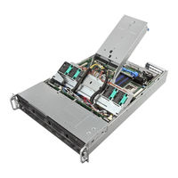
Intel R2000LH2 Technical Product Specification (126 pages)
Product Family Server System R2000LH2/T2
Brand:
Intel
| Category:
Server
| Size: 3.39 MB
Table of Contents
Revision History
2
Table of Contents
3
1 Introduction
13
Chapter Outline
13
Server Board Use Disclaimer
14
2 Product Family Overview
15
Figure 1. System Overview
15
Figure 2. System Assembly
15
Table 1. Server System
16
Table 2. System Feature Set
16
Chassis Dimensions
18
Figure 3. Chassis Dimensions
18
System Level Environmental Limits
19
Table 3. System Environmental Limits Summary
19
System Features and Options Overview
21
Hot Swap Hard Drive Bay and Front Panel Options
21
Figure 4. System Components Overview
21
Figure 5. 2.5" Hot Swap Hard Drive Bay - 8 Drive Configuration
21
Figure 6. 3.5" Hotswap Hard Drive Bay - 4 Drive Configuration
21
Back Panel Features
22
Front Control Panel Options
22
Figure 7. Back Panel Feature Identification
22
Figure 8. Front Control Panel Options
22
Table 4 Front Control Panel Options
22
Figure 9. Intel Server Board S4600LH2/LT2
24
Server Board Features Overview
24
Available Front Bezel Support
25
Figure 10. Optional Front Bezel (Intel Product Order Code - A2UBEZEL)
25
Figure 11. Installing the Front Bezel
25
Available Rack and Cabinet Mounting Kit Options
26
3 Power Subsystem
27
Figure 12. Power Supply
27
Mechanical Overview
28
Figure 13. Power Supply Module Mechanical Drawing
28
Figure 14. Power Supply Module
28
Figure 15. AC and DC Power Supplies - Connector View
29
Power Connectors
30
Power Supply Module Card Edge Connector
30
Table 5. Power Supply Module Output Power Connector Pin-Out
30
Power Supply Module Efficiency
31
Table 6. 1600 Watt (AC) Power Supply Efficiency (Gold)
31
AC and DC Power Cord Specification Requirements
32
Figure 16. AC Power Cord
32
Figure 17. DC Power Cord
32
Table 7. AC Power Cord Specifications
32
AC Input Specifications
33
Power Factor
33
AC Input Voltage Specification
33
AC Line Isolation Requirements
33
AC Line Dropout/Holdup
33
Table 8. Power Factor
33
Table 9. AC Input Voltage Range
33
AC Line Fuse
34
AC Inrush
34
AC Line Transient Specification
34
Table 10. AC Line Dropout/Holdup
34
Table 11. AC Line Sag Transient Performance
34
Susceptibility Requirements
35
Electrostatic Discharge Susceptibility
35
Fast Transient/Burst
35
Radiated Immunity
35
Surge Immunity
35
Table 12. AC Line Surge Transient Performance
35
Table 13. Performance Criteria
35
Power Recovery
36
Voltage Interruptions
36
Protection Circuits
36
Over-Current Protection (OCP)
36
Over-Voltage Protection (OVP)
36
Table 14. Power Supply over Current Protection
36
Over-Temperature Protection (OTP)
37
Table 15. over Voltage Protection (OVP) Limits
37
1600W DC Power Supply Support
38
Power Supply Module Efficiency
38
DC Inlet Connector
38
DC Input Voltage Specification
38
DC Holdup/Dropout Time
38
Table 16. 1600 Watt (DC) Power Supply Efficiency (Platinum)
38
Table 17. 1600 Watt (DC) Power Supply Efficiency (Platinum)
38
Table 18. DC Holdup/Dropout Time
38
DC Line Fuse
39
DC Inrush
39
DC Line Surge Voltages (Line Transients)
39
Figure 18. 75VDC Test
39
Residual Voltage Immunity in Standby Mode
40
Protection Circuits
40
Figure 19. 0VDC Test
40
Table 19. Line Voltage Transient Limits
40
Over Temperature Protection (OTP)
41
Table 20. over Current Protection
41
Table 21. over Voltage Protection Limits
41
Cold Redundancy Support
42
Powering on Cold Standby Supplies to Maintain Best Efficiency
42
Table 22. Example Load Share Threshold for Activating Supplies
42
Powering on Cold Standby Supplies During a Fault or over Current Condition
43
BMC Requirements
43
Power Supply Turn on Function
43
Closed Loop System Throttling (CLST)
44
Smart Ride through (Smart)
44
3.10 Power Supply Status LED
44
Table 23. LED Indicators
44
4 Thermal Management
45
Thermal Operation and Configuration Requirements
45
Thermal Management Overview
47
Set Throttling Mode
47
Altitude
47
Set Fan Profile
48
Fan PWM Offset
48
Quiet Fan Idle Mode
48
Thermal Sensor Input for Fan Speed Control
49
Figure 20. Fan Control Model
50
System Fans
51
Figure 21. System Fan Identification
51
Figure 22. System Fan Assembly
52
Figure 23. Upper and Lower System Fan Connections
53
Figure 24. Lower Fan Board
53
Lower Fan Board
53
Table 24. Lower Fan Connector Pin-Out
53
Figure 25. Lower Fan Board Dimensions
54
Figure 26. Upper Fans Connectors on PDB
54
Table 25. Upper Fan Connector Pin-Out (Fans 8-11)
54
Upper Fans
54
Power Supply Module Fan
55
5 System Storage and Peripheral Drive Bays Overview
56
2.5" Hard Disk Drive Support
56
Figure 27. 8 X 2.5" Hard Drive Configuration
56
Figure 28. 2.5" Hard Disk Drive Assembly
57
Figure 29. 2.5" Drive Leds
57
Table 26. 2.5" Drive Status LED States
57
Table 27. 2.5" Drive Activity LED States
57
2.5" Drive Hot-Swap Backplane Overview
58
Figure 30. 2.5" Drive Hot-Swap Backplane Assembly
58
Figure 31. 2.5" Drive Hot-Swap Backplane - Front Side
58
Figure 32. 2.5" Drive Hot-Swap Backplane - Back Side
59
3.5" Hard Disk Drive Support
60
Figure 33. 4 X 3.5" Hard Drive Configuration
60
Figure 34. 3.5" Hard Disk Drive Assembly
60
3.5" Drive Hot-Swap Backplane Overview
61
Figure 35. 3.5" Drive Leds
61
Table 28. 3.5" Drive Status LED States
61
Table 29. 3.5" Drive Activity LED States
61
Figure 36. 3.5" Drive Hot-Swap Backplane Assembly
62
Figure 37. 3.5" Drive Hot-Swap Backplane - Front Side
62
Figure 38. 3.5" Drive Hot-Swap Backplane - Back Side
63
Optical Drive Support
64
Figure 39. Optical Drive Support
64
Figure 40. Optical Drive Assembly
64
Solid State Drive (SSD) Support
65
Figure 41. 2.5" Solid State Drive (SSD) Mounting Option
65
Low Profile Eusb SSD Support
66
Figure 42. Low Profile Eusb SSD Support
66
SATA DOM Support
67
Figure 43. Innodisk* Low Profile SATA DOM
67
6 Storage Controller Options Overview
68
Embedded SATA/SAS Controller Support
68
Figure 44. Embedded SATA/SAS Controller Support
68
Table 30. Intel ® RAID C600 Upgrade Key Options
69
Embedded Software RAID Support
70
Intel ® Embedded Server RAID Technology 2 (ESRT2)
70
Intel ® Rapid Storage Technology (Rste)
70
Table 30. Intel
70
7 Front Control Panel and I/O Panel Overview
72
I/O Panel Features
72
Figure 45. Front I/O Panel Features
72
Control Panel Features
73
Figure 46. Front Control Panel Features
73
Table 31. System Status LED State Definitions
74
Table 32. Power/Sleep LED Functional States
76
8 Intel Local Control Panel
77
Figure 47. Intel Local Control Panel Option
77
LCD Functionality
78
Figure 48. LCP Background Color During Normal Operation
78
Figure 49. LCP Background Color During an Error
78
Main Menu
80
Figure 50. LCP Main Menu
80
Event Menu
81
Figure 51. LCP Event Menu
81
View Menu
82
System FW Version (Sysfwver)
82
System Information (Sysinfo)
82
Figure 52. LCP View Menu
82
Figure 53. System Firmware Versions Menu
82
Figure 54. System Information Menu
82
BMC IP Configuration
83
RMM4 IP Configuration
83
Figure 55. LCP - BMC IP Configuration
83
Figure 56. LCP - RMM4 IP Configuration
83
Power
84
Last Post Code (Last PC)
84
Figure 57. LCP - Power Consumed by the System Currently
84
Figure 58. LCP - Last BIOS Post Code
84
Config Menu
85
IP Version
85
Bmc Ip
85
Figure 59. LCP - Configure Menu Items
85
Figure 60. LCP - IP Version Configuration Screen
85
Figure 61. LCP - BMC IP Configuration Menu
85
Figure 62. LCP - BMC IP Source Configuration Menu
85
Figure 63. Screen Shots for Configuring IP Address, Subnet Mask, and Gateway
86
Rmm4 Ip
87
Boot Device
87
Figure 64. State Transition Diagram for Setting IP Address
87
Figure 65. Boot Options Configuration Menu
87
Banner
88
Figure 66. Banner Configuration Menu
88
9 PCI Riser Card Support
89
Riser Slot Overview
89
Figure 67. Pcie Risers and Add-In Cards
90
GPGPU Support on the Pcie Risers
91
GPGPU Power
91
GPGPU Cable
91
Figure 68. GPGPU Cable
91
Table 33. GPGPU Aux Connector Pin-Out (J9 and J10)
91
Wattage Limitation of the PCI Loading
92
Table 34. Wattage Limitation of Pcie Loading
92
Riser Slot Mapping
93
Figure 69. IO Riser CPU Mapping
93
Riser Card Drawing
94
Figure 70. Right Riser Card Drawing
94
Figure 71. Left Riser Card Drawing
94
10 Additonal System Boards
95
Power Distribution Board (PDB)
95
10.2 Setting the Power Supply Addressing for Pmbus and FRU
95
10.3 12V over Current Protection
95
Over Current Protection Circuits
95
Table 35. over Current Protection Circuits
95
10.4 Power Supply Keying
96
10.5 PDB Connectors
96
Grounding
96
Power Supply Card Edge Connectors
96
Table 36. Power Supply Card Edge Connector Pin-Out P8 and P9
96
Motherboard Power Connectors
97
Table 37. Main Power (J8) Connector Pin-Out
97
Table 38. Main Power (J6) Connector Pin-Out
97
Motherboard Signal from PDB
98
GPGPU Power Connectors
98
Figure 72. PDB
98
Table 39. Power Control Signals Pin-Out (J5)
98
Table 40. GPGPU Aux Connector Pin-Out (J9 and J10)
98
Upper Fan Connector
99
Figure 73. Upper Fans Connectors on PDB
99
Table 41. Upper Fan Connector Pin-Out (Fans 8-11)
99
10.6 PDB Drawing
100
Figure 74. PDB Drawing
100
11 Front Panel
101
Figure 75. SSI Common Front Panel Board
101
Table 42. SSI Front Panel Connector Pin-Out (Baseboard)
101
12 IO Module Support
102
Figure 76. Mezzanine Support
102
Table 43. Intel I/O Modules
102
Figure 77. RMM4 Installation
103
13 Intel Intelligent Power Node Manager (NM)
104
13.1 Overview
104
Hardware Requirements
104
Features
104
Role of BMC in NM
105
ME System Management Bus (Smbus) Interface
106
Peci 3.0
106
PECI Proxy
106
Figure 78. PECI Proxy
106
ME Power and Firmware Startup
107
ME Firmware Update
107
NM Discovery OEM SDR
107
Smart/Clst
108
Appendix A: Integration and Usage Tip
109
Appendix B: POST Code Diagnostic LED Decoder
110
Figure 79. POST Diagnostic LED Location
110
Table 44. POST Progress Code LED Example
111
Table 45. POST Progress Codes
111
Table 46. MRC Progress Codes
114
Table 47. MRC Fatal Error Codes
115
Appendix C: POST Code Errors
116
Table 48. POST Error Messages and Handling
117
Table 49. POST Error Beep Codes
122
Table 50. Integrated BMC Beep Codes
122
Glossary
123
Reference Documents
126
Advertisement
Intel R2000LH2 Service Manual (86 pages)
Server System
Brand:
Intel
| Category:
Server
| Size: 6.43 MB
Table of Contents
Important Safety Instructions
3
Instrucciones de Seguridad Importantes
3
Safety Information
3
Wichtige Sicherheitshinweise
3
About this Manual
5
Additional Information and Software
5
Manual Organization
5
Preface
5
Table of Contents
7
List of Tables
12
1 Server System Features
13
Server System Feature Overview
13
Figure 1. Intel Server System R2000LH2/LT2
13
Table 3. Intel Server System R2000LH2/LT2 Feature Summary
13
Wattage Limitation of the PCI Loading
15
Power Rating
15
Table 4. Wattage Limitation of the Pcie Loading
15
Table 5. Power Rating of the Power Supply
15
Server System Components
16
Hot Swap Hard Drive Bay and Front Panel Options
16
Figure 2. Intel Server System R2000LH2/LT2 Components
16
Figure 3. 3.5" Hot Swap Hard Drive Bay - 4 Drive Configuration
16
Figure 4. 2.5" Hot Swap Hard Drive Bay - 8 Drive Configuration
16
Front Panel
17
Back Panel
17
Figure 5. Front Panel Options
17
Figure 6. Back Panel Feature Identification
17
Server Board Components
18
Figure 7. Server Board Connector and Component Locations
19
System Recovery Jumpers
20
Figure 8. Configuration Jumpers
20
Peripheral Devices
21
Figure 9. Optional Peripherals (4X3.5-Inch Hard Drive Bays as Shown)
21
Table 6. Hard Disk Drive Options
21
Figure 10. Front Bezel (Front View)
22
Figure 11. 4 X 3.5-Inch Hard Drive Backplane Components (Front View)
22
Figure 12. 4 X 3.5-Inch Hard Drive Backplane Components (Rear View)
23
Figure 13. 8 X 2.5-Inch Hard Drive Backplane Components (Front View)
23
Figure 14. 8 X 2.5-Inch Hard Drive Backplane Components (Rear View)
23
Advanced Management Options
24
2 Hardware Installations and Upgrades
25
Before You Begin
25
Tools and Supplies Needed
25
System Reference
25
Cable Routing
25
For System with 4 X 3.5" Hot Swap Hard Drive Bay
25
Figure 15. Cable Routing - 4 X 3.5" Hot Swap HDD
26
For System with 8 X 2.5" Hot Swap Hard Drive Bay
27
Figure 16. Cable Routing - 8 X 2.5" Hot Swap HDD
27
Fan Connections
28
Figure 17. System Fan Order
28
Figure 18. Connecting the Fan Power Cables to the Fan Board and PDB
28
Removing and Installing the Front Bezel (Optional)
29
Removing the Front Bezel
29
Installing the Front Bezel
29
Figure 19. Removing the Front Bezel
29
Figure 20. Installing the Front Bezel
29
Removing and Installing the Front Fan Bezel
30
Removing the Front Fan Bezel
30
Installing the Front Fan Bezel
30
Figure 21. Removing the Front Fan Bezel
30
Figure 22. Installing the Front Fan Bezel
30
Removing and Installing the Rack Handles
31
Removing the Rack Handles
31
Installing the Rack Handles
31
Figure 23. Removing the Rack Handle
31
Figure 24. Installing the Rack Handle
31
Removing and Installing the Power Supply Module(S)
32
Removing the Power Supply Module(S)
32
Installing a Power Supply Module(S)
32
Removing and Installing the System Cover
32
Removing the System Cover
32
Figure 25. Removing the Power Supply Module
32
Figure 26. Installing the Power Supply Module
32
Installing the System Cover
33
Figure 27. Removing the System Cover
33
Figure 28. Installing the System Cover
33
Removing and Installing the Front End Module
34
Removing the Front End Module
34
Installing the Front End Module
34
Figure 29. Removing the Front End Module
34
Figure 30. Installing the Front End Module
34
Removing and Installing the PCI Riser Assembly
35
Removing the PCI Riser Assembly
35
Installing the PCI Riser Assembly
35
Figure 31. Removing the PCI Riser Assembly
35
Figure 32. Installing the PCI Riser Assembly
35
Installing and Removing a PCI Add-In Card
36
Installing a PCI Add-In Card
36
Figure 33. Installing a Half-Length PCI Add-In Card
36
Removing a PCI Add-In Card
37
Figure 34. Installing a Full-Length PCI Add-In Card
37
Figure 35. Removing a Half-Length PCI Add-In Card
37
Removing and Installing the Air Duct
38
Figure 36. Removing a Full-Length PCI Add-In Card
38
Figure 37. Removing the Air Duct
39
Figure 38. Installing the Air Duct
39
Installing the Air Duct
39
Removing the Air Duct
39
Removing and Installing the Processor Heatsink(S)
40
Removing Processor Heatsink(S)
40
Installing Processor Heatsink(S)
40
Figure 39. Removing Processor Heatsink
40
Installing or Replacing the Processor
41
Figure 40. Installing Processor Heatsink
41
Figure 41. Installing Processor - Remove the Cover
42
Figure 42. Installing Processor - Open the Socket Lever
42
Figure 43. Installing Processor - Open the Load Plate
42
Installing the Processor
42
Installing and Removing the Memory
43
Figure 44. Installing Processor - Install the Processor
43
Figure 45. Installing Processor - Close the Load Plate
43
Figure 46. Installing Processor - Latch the Locking Lever
43
Installing Memory
44
Removing Memory
44
Installing and Removing Hard Drive
44
Figure 47. Installing Memory
44
Figure 48. Installing Hard Disk Drive - Removing 3.5" HDD Carrier
45
Figure 49. Installing Hard Disk Drive - Removing 3.5" HDD Interface Bracket
45
Figure 50. Installing Hard Disk Drive - Installing 3.5" HDD
45
Installing a Hard Disk Drive into 3.5" Hot Swap Hard Drive Carrier
45
Figure 51. Installing Hard Disk Drive - Installing 2.5" HDD
46
Figure 52. Installing Hard Disk Drive - Inserting 3.5" HDD Assembly
46
Figure 53. Installing Hard Disk Drive - Removing 2.5" HDD Carrier
47
Figure 54. Installing Hard Disk Drive - Removing Plastic Drive Blank
47
Figure 55. Installing Hard Disk Drive - Installing 2.5" HDD
47
Installing a Hard Disk Drive into 2.5" Hot Swap Hard Drive Carrier
47
Installing and Removing a Slimline Optical Drive
48
Installing a Slimline Optical Drive
48
Figure 56. Installing Hard Disk Drive - Inserting 2.5" HDD Assembly
48
Figure 57. Installing the Plastic Guide to the Optical Drive
48
Removing a Slimline Optical Drive
49
Installing and Removing the Intel I/O Expansion Module
49
Figure 58. Installing an Optical Drive
49
Figure 59. Removing the Slimline Optical Drive
49
Before Installing Intel ® I/O Expansion Module at the Left Edge of the Board (Optional)
50
Figure 60. Installing Intel I/O Expansion Module
50
Figure 61. Installing Intel ® I/O Expansion Module
51
Installing Intel I/O Expansion Module
51
Removing Intel I/O Expansion Module
52
Figure 62. Removing Intel I/O Expansion Module
52
Installing and Removing the Intel
53
Remote Management Module 4
53
Installing the Intel ® RMM4 Lite
53
Figure 63. Installing the Intel
53
Install the Intel RMM4 NIC
54
Removing the Intel RMM4 Lite
54
Installing the Intel ® RMM4 Lite
54
Removing the Intel RMM4 NIC
54
Figure 64. Installing the Intel
54
Figure 65. Removing the Intel
54
Installing and Removing an Internal Solid State Drive
55
Installing a Solid State Drive
55
Figure 66. Installing a SSD
55
Removing a Solid State Drive
56
Figure 67. Removing a SSD
56
Installing and Removing the Intel RAID Smart Battery
57
Installing the Intel RAID Smart Battery
57
Figure 68. Installing the Intel
57
Removing the Intel RAID Smart Battery
58
Installing and Removing the Server Board
58
Figure 69. Removing the Intel
58
Figure 70. Removing the Server Board
59
Figure 71. Installing the Server Board
59
Installing the Server Board
59
Removing the Server Board
59
Replacing the Backup Battery
60
Figure 72. Replacing the Backup Battery
60
Replacing a Redundant Fan Module
61
Figure 73. Replacing a System Fan
61
Replacing the Backplane
62
Removing the Backplane
62
Installing the Backplane
62
Figure 74. Removing the Backplane
62
Figure 75. Installing the Backplane
62
Replacing the Lower Fan Board
63
Removing the Lower Fan Board
63
Figure 76. Removing the Lower Fan Board
63
Installing the Lower Fan Board
64
Replacing the Front Video and USB Module
64
Figure 77. Installing the Lower Fan Board
64
Figure 78. Removing the Front Video and USB Module
65
Removing the Front Video and USB Module
65
Installing the Front Video and USB Module
66
Installing and Removing the LCP Module
66
Figure 79. Installing the Front Video and USB Module
66
Figure 80. Installing the LCP Module
67
Installing the LCP Module
67
Figure 81. Removing the LCP Module
68
Removing the LCP Module
68
Install the Bezel (Optional)
69
Install the System into Rack (Optional)
69
Figure 82. Slides Component
69
Figure 83. Install Slides to Rack
70
Figure 84. Install Inner Member to Chassis
70
Installing the Chassis into Rack
70
Figure 85. Install Chassis to Fixed Slides
71
Figure 86. Extend Slides
71
Removing the Chassis from Rack
71
Figure 87. Remove Inner Member from Chassis
72
3 Server Utilities
73
Using the BIOS Setup Utility
73
Starting Setup
73
Setup Navigation Keyboard Commands
73
Table 7. BIOS Setup: Keyboard Command Bar
73
Setup Screen Menu Selection Bar
74
BIOS Setup Utility Screens
74
Map of Screens and Functionality
75
Table 8. Screen Map
75
Appendix A: Regulatory and Compliance Information
77
Appendix B: Safety Information
78
Appendix C: Installation/Assembly Safety Instructions
79
Appendix D: Getting Help
80
Warranty Information
80
Appendix E: Intel Server Issue Report Form
81
Appendix F: Warranty
85
Limited Warranty for Intel Chassis Subassembly Products
85
Extent of Limited Warranty
85
Warranty Limitations and Exclusions
85
Limitations of Liability
86
How to Obtain Warranty Service
86
Telephone Support
86
Returning a Defective Product
86
Intel R2000LH2 Quick Installation User's Manual (20 pages)
Server System
Brand:
Intel
| Category:
Server
| Size: 15.77 MB
Table of Contents
Table of Contents
3
System Overview
5
General Installation Process
6
Preparing System
6
Remove Power Supply Module
6
Remove Top Cover
6
Remove Add-In Card Riser Assembly
6
Remove Air Duct
6
Remove Processor Heatsink(S)
7
Install Processor(S)
7
Install Processor Heatsink(S)
8
Install Memory Modules
8
Install Hard Drives
9
Install Optical Drive
12
Install Intel® I/O Expansion Module (Optional)
12
Install Intel® RAID C600 Upgrade Key (Optional)
12
Install Air Duct
13
Install Add-In Card(S)
13
Install Add-In Card Riser Assembly
14
Install Intel® RAID Smart Battery (Optional)
14
Install Top Cover
14
Install Power Supply Module
14
Finishing up
15
Software
15
Reference
16
Advertisement
Advertisement
Related Products
Intel R2000SC
Intel R2000LT2
Intel R2000GL series
Intel R2000GZ series
Intel R200LH2
Intel R2000WF series
Intel R2000BB series
Intel R2000WFTF Series
Intel R2308WT Series
Intel R2208WT Series
Intel Categories
Motherboard
Computer Hardware
Server
Server Board
Desktop
More Intel Manuals
Login
Sign In
OR
Sign in with Facebook
Sign in with Google
Upload manual
Upload from disk
Upload from URL