Table of Contents
Advertisement
Quick Links
Advertisement
Table of Contents

Related Manuals for Juniper MX10004


Summary of Contents for Juniper MX10004
- Page 1 MX10004 Universal Routing Platform Hardware Guide Published 2022-11-30...
- Page 2 The Juniper Networks product that is the subject of this technical documentation consists of (or is intended for use with) Juniper Networks software. Use of such software is subject to the terms and conditions of the End User License Agreement ("EULA") posted at https:/ /support.juniper.net/support/eula/.
-
Page 3: Table Of Contents
MX10004 Optional Equipment | 25 MX10004 Cooling System | 26 MX10004 Cooling System and Airflow | 26 MX10004 Fan Tray LEDs and Fan Tray Controller LEDs | 31 MX10004 Power System | 38 JNP10K-PWR-AC2 Power Supply | 38 JNP10K-PWR-AC2 Power Specifications | 40... - Page 4 Power Requirements for MX10004 Components | 88 Calculate Power Requirements of an MX10004 Router | 89 How to Calculate the Power Consumption of Your MX10004 Router Configuration | 90 How to Calculate the Number of Power Supplies Required for Your MX10004...
- Page 5 Mount Kit | 120 Install the Front Door on an MX10004 Router | 127 Install a Front Door Without the Air Filter on an MX10004 Router | 128 Install a Front Door with Filter | 130 Connect the MX10004 to Power | 134...
- Page 6 Remove an MX10004 Fan Tray Controller | 170 MX10004 Switch Fabric Board Maintenance | 172 How to Handle and Store MX10004 Switch Fabric Board | 173 How to Hold an SFB | 173 How to Store a Switch Fabric Board | 174...
- Page 7 Locate the Serial Number ID Label on an MX10004 Power Supply | 225 Locate the Serial Number ID Labels on MX10004 Fan Trays and Fan Tray Controllers | 227 Locate the Serial Number ID Labels on MX10004 Routing and Control Boards | 228...
- Page 8 Locate the Serial Number ID Labels on an MX10004 Switch Fabric Board | 230 Contact Customer Support to Obtain a Return Materials Authorization for an MX10004 Router or Component | 230 How to Pack an MX10004 Router or Component for Shipping | 231...
- Page 9 DC Power Wiring Terminations Warning | 272 Multiple Power Supplies Disconnection Warning | 273 TN Power Warning | 274 Action to Take After an Electrical Accident | 274 Agency Approvals for MX10004 Routers | 275 Compliance Statements for EMC Requirements for the MX10004 Router | 277...
-
Page 10: About This Guide
About This Guide Use this guide to install hardware and perform initial software configuration, routine maintenance, and troubleshooting for the MX10004 Universal Routing Platform. After completing the installation and basic configuration procedures covered in this guide, refer to the Junos OS documentation... -
Page 11: Overview
MX10004 Chassis | 18 MX10004 Cooling System | 26 MX10004 Power System | 38 MX10004 Routing and Control Board Components and Descriptions | 56 MX10004 Switch Fabric Board | 64 MX10K-LC2101 Line Card | 67 MX10K-LC480 Line Card | 70... -
Page 12: Mx10004 System Overview
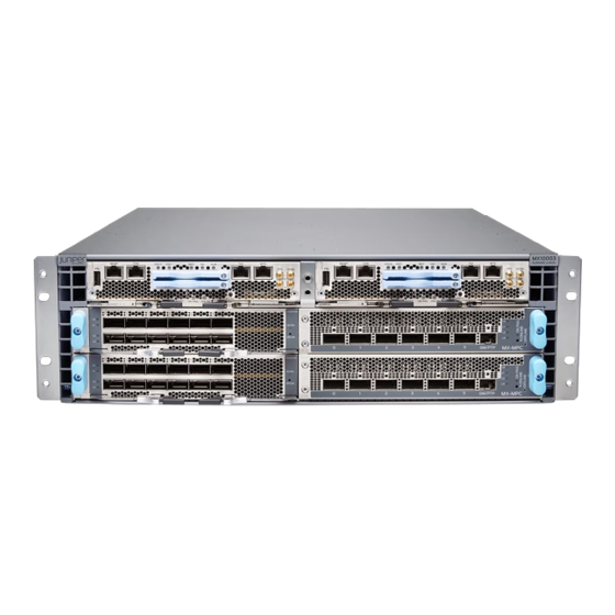
The MX10004 router is the most compact, high-density, and power-efficient modular router in the MX10000 line of modular packet-routing transport routers. At only 7 U in height, the MX10004 is designed for today’s space-constrained facilities. Like the larger MX10000 routers, the MX10004 supports Juniper Networks’... - Page 13 (NSR). Chassis Description The MX10004 router is 7-U tall. You can install up to six MX10004 routers in a standard 42-U rack with adequate cooling and power. All key MX10004 router components are field-replaceable units (FRUs). Figure 1 on page 4...
- Page 14 Figure 1: MX10004 Chassis Front Figure 2: MX10004 Chassis Rear...
- Page 15 "MX10004 Chassis Physical Specifications" on page Switch Fabric Boards Switch Fabric Boards (SFBs) create the switch fabric for the MX10004. Each SFB has a set of connectors to mate the line cards and the Routing and Control Board (RCB) to the switch fabric. See...
- Page 16 You can order the MX10004 with different SFB configurations that enable you to grow your system as needed. See "MX10004 Components and Configurations" on page Figure 4: JNP10004-SF2 Switch Fabric Board Routing and Control Board The Routing and Control Board (RCB) contains a Routing Engine and is responsible for system management and system control in the MX10004.
- Page 17 The MX10004 has four horizontal line card slots. The line cards combine a Packet Forwarding Engine and Ethernet interfaces enclosed in a single assembly. The MX10004 line card architecture is based on a number of identical, independent Packet Forwarding Engine slices. Line cards are FRUs that you can install in the line card slots labeled 0 through 3 (top to bottom) on the front of the chassis.
- Page 18 Figure 6 on page 8 for an example of an MX10004 line card. Figure 6: The MX10K-LC9600 Line Card Cooling System The cooling system in an MX10004 consists of two fan trays (see Figure 7 on page 8) and two fan tray controllers (see...
- Page 19 Figure 8 on page Figure 8: Fan Tray Controller JNP10004-FTC2 Power Supplies The MX10004 routers support AC, DC, high-voltage alternating current (HVAC), and high-voltage direct current (HVDC) through the following power supplies: • JNP10K-PWR-AC2 • JNP10K-PWR-DC2 Power supplies for the MX10004 are load-sharing, hot-removable, hot-insertable FRUs. The router operates with three power supplies.
- Page 20 CAUTION: Avoid mixing power supply models in the same chassis in a running environment. Figure 9: JNP10K-PWR-AC2 Power Supply Figure 10: JNP10K-PWR-DC2 Power Supply Table 1 on page 11 provides an overview of the differences between the power supplies.
-
Page 21: Mx10004 Components And Configurations
5000 W, single feed; 5500 W, dual feed JNP10K-PWR-DC2 DC only 2750 W, single feed; 5500 W, dual feed Software The Juniper Networks MX10004 Universal Routing platform runs on the Junos OS 22.3R1 operating system. MX10004 Components and Configurations IN THIS SECTION MX10004 Configurations | 11... - Page 22 Table 2: MX10004 Hardware Configurations Router Configuration Configuration Components MX10004-BASE • Chassis (JNP10004-CHAS) • One RCB (JNP10K-RE1, JNP10K-RE1-LT or JNP10K-RE1-128) • One RCB cover (JNP10K-RE-BLNK) • Two fan tray controllers (JNP10004-FTC2) • Two fan trays (JNP10004-FAN2) • Two AC power supplies (JNP10K-PWR-AC2) or two DC power supplies (JNP10K-PWR-DC2) •...
- Page 23 (Continued) Table 2: MX10004 Hardware Configurations Router Configuration Configuration Components MX10004-3F-BASE • Chassis (JNP10004-CHAS) • One RCB (JNP10K-RE1, JNP10K-RE1-LT or JNP10K-RE1-128) • One RCB cover (JNP10K-RE-BLNK) • Two fan tray controllers (JNP10004-FTC2) • Two fan trays (JNP10004-FAN2) • Two AC power supplies (JNP10K-PWR-AC2) or two DC power supplies (JNP10K-PWR-DC2) •...
-
Page 24: Mx10004 Component Redundancy
RCBs for your router configuration, you must order them separately. MX10004 Component Redundancy The MX10004 router is designed so that no single point of failure can cause the entire system to fail. The following major hardware components in the redundant configuration provide redundancy: •... -
Page 25: Mx10004 Hardware And Cli Terminology Mapping
Power Budget: Insufficient Power major alarm is raised. The MX10004 router also supports power source redundancy. Four sets of lugs are provided for the JNP10K-PWR-DC2 cables, and two AC power cords are provided for each JNP10K-PWR-AC2 power supply. - Page 26 (Continued) Table 3: CLI Equivalents of Terms Used in Documentation for MX10004 Routers Hardware Description (CLI) Value (CLI) Item in Additional Information Item (CLI) Documentati n is a FPC ( Abbreviation for The variable Line card Understanding Interface the Flexible PIC...
- Page 27 (Continued) Table 3: CLI Equivalents of Terms Used in Documentation for MX10004 Routers Hardware Description (CLI) Value (CLI) Item in Additional Information Item (CLI) Documentati n is a SFB ( This field indicates: The variable Fabric plane show chassis sfb value in the range of •...
-
Page 28: Mx10004 Chassis
The MX10004 modular chassis is a rigid sheet-metal structure that houses the other router components. You can mount up to six MX10004 routers in a standard 19-in. 4-post rack (42 U), provided that the rack can bear the combined weight and that adequate power and cooling is available. - Page 29 Figure 11 on page 19 to help identify the major components. See Table 4 on page 20 for the physical specifications of the chassis of these components. Figure 11: Front View of the MX10004 Router RCBs Line cards — —...
- Page 30 Table 4: MX10004 Router Physical Specifications Description Weight Height Width Depth Chassis, MX10004- 217 lbs (99 kg) 12.2 in. (31 cm) 17.4 in. (44.2 cm) 36.6 in. (92.96 cm) BASE AC or DC with JNP10004- NOTE: The outer configuration FAN2 fan trays...
-
Page 31: Mx10004 Field-Replaceable Units
• Hot-pluggable—You can remove and replace these components without powering off the router, but the routing function is interrupted until you replace the component. Table 5 on page 21 lists the FRUs and their types for the MX10004 routers. Table 5: FRUs in a MX10004 Type Power supplies Hot-insertable and hot-removable. - Page 32 Hot-insertable and hot-removable. NOTE: Line cards are not part of the base or redundant configuration. You must order them separately. NOTE: If you have a Juniper Care service contract, register any addition, change, or upgrade of hardware components at https:/...
-
Page 33: Mx10004 Status Panel
MX10004 Status Panel The MX10004 status panel shows the overall status of the chassis. The MX10004 chassis ships with an enhanced power bus to future-proof the chassis for potential power growth. The status panel indicates the chassis status through a set of five bicolor LEDs. It has an Azure blue stripe along the left side of the LEDs. - Page 34 (Continued) Table 6: Status Panel LEDs on an MX10004 Name Color State Description Alarm (Bell symbol) Yellow No minor alarms are active. On steadily A minor alarm is active. No major alarms are active. On steadily A major alarm is active.
-
Page 35: Mx10004 Optional Equipment
(Continued) Table 6: Status Panel LEDs on an MX10004 Name Color State Description Yellow Blinking A hardware error occurred in one or more SFBs. None All the SFBs are offline. LINE CARDS Green On steadily All installed line cards are online. -
Page 36: Mx10004 Cooling System
Fan Tray Controller | 29 Airflow Direction in the MX10004 | 30 The cooling system in an MX10004 chassis consists of dual fan trays (JNP10004-FAN2) with matching dual fan tray controllers (JNP10004-FTC2). Each fan tray requires a companion fan tray controller to be installed and operational to be hot-insertable and hot-removable. - Page 37 Two handles on each front faceplate facilitate handling of the fan tray. See Figure 13 on page Figure 14 on page Figure 13: JNP10004-FAN2 Fan Tray Figure 14: Installed Fan Trays on an MX10004 Power supplies Fan trays —...
- Page 38 Table 7: Fan Tray Specifications Specification JNP10004-FAN2 Corresponding fan tray controller model JNP10004-FTC2 Number of fans per fan tray Number of fans per chassis Fan numbering 0 through 11 Volume flow at 100 percent 948 CFM for both fan trays Height 12.08 in.
- Page 39 Fan Tray Controller The MX10004 supports two fan tray controllers to provide the control logic and power to hot-insert and hot-remove a fan tray JNP10004-FTC2—Supports model JNP10004-FAN2; see Figure 15 on page Figure 15: Fan Tray Controller JNP10004-FTC2 WARNING: Do not mix the fan tray controller models. Use only the supported fan tray model for each fan tray controller.
- Page 40 Fabric Boards (SFBs), and exits from the fan trays and the power supplies. See Figure 16 on page Figure 16: Airflow Through an MX10004 The fan tray continues to operate indefinitely and provide sufficient cooling even when a single rotor fails, provided the room temperature is within the operating range.
-
Page 41: Mx10004 Fan Tray Leds And Fan Tray Controller Leds
MX10004 Fan Tray LEDs and Fan Tray Controller LEDs IN THIS SECTION Fan Tray LEDs | 31 Fan Tray Controller LEDs | 36 Each fan tray has a set of LEDs, and each corresponding fan tray controller also has a set of LEDs. - Page 42 SFB 3 through SFB 5. Fan tray controller status LED — Table 9 on page 32 describes the functions of the fan tray LEDs. Table 9: Fan Tray LEDs on an MX10004 Name Color State Description FAN (fan status)
- Page 43 (Continued) Table 9: Fan Tray LEDs on an MX10004 Name Color State Description Amber Blinking An error has been detected in the fan tray controller. Replace the fan tray controller as soon as possible. The fan tray controller is located behind the fan tray above the SFBs.
- Page 44 (Continued) Table 9: Fan Tray LEDs on an MX10004 Name Color State Description Amber Blinking An error has been detected in SFB 1. Replace the SFB as soon as possible. The SFB is located behind the left fan tray and is the middle SFB in the group of 3.
- Page 45 (Continued) Table 9: Fan Tray LEDs on an MX10004 Name Color State Description Amber Blinking An error has been detected in SFB 3. Replace the SFB as soon as possible. The SFB is located behind the right fan tray and is the left-most SFB of the group of 3.
- Page 46 LEDs are located on the right of the controller panel. Figure 18 on page 36 shows the location of the LEDs on the JNP10004-FTC2 fan tray controller faceplate. Figure 18: Fan Tray Controller LEDs on an MX10004 Fan tray controller power Fan tray controller status —...
- Page 47 Table 10: Fan Tray Controller LEDs on an MX10004 Name Color State Description PWR (fan tray controller Green On steadily The fan tray controller has power and is power) operating normally. Amber Blinking A power error has been detected in the fan tray controller.
-
Page 48: Mx10004 Power System
MX10004 Grounding Cable and Lug Specifications | 55 You can install up to three power supplies in an MX10004 router in the slots labeled PSU0 through PSU2 (top to bottom) located in the rear of the chassis. The JNP10K-PWR-AC2 is designed for AC, high- voltage alternating current (HVAC) and high-voltage direct current (HVDC) environments and can be set for single or dual feeds and high or low output settings. - Page 49 recommend that you not mix DIP switch settings in your system. See Table 11 on page 40 information about the input and output voltages when you use the DIP switches. The JNP10K-PWR-AC2 power supply has internal fans that contribute to chassis cooling. Consequently, all three power supplies must be present in a running chassis to provide adequate airflow.
-
Page 50: Jnp10K-Pwr-Ac2 Power Specifications
AC power before loading the system with power. JNP10K-PWR-AC2 Power Specifications The JNP10K-PWR-AC2 power supply supports AC, high-voltage alternating current (HVAC) and high- voltage direct current (HVDC). Table 12 on page 41 lists the power specifications for the AC power supply (JNP10K-PWR-AC2) used in an MX10004 chassis. - Page 51 Table 12: Power Specifications for a JNP10K-PWR-AC2 Power Supply Specification Value AC input voltage 180–305 VAC DC input voltage 190–410 VDC Input current rating 28.5 A DC output power 12.3 V, 5500 W with dual feed and 5000 W with single feed Table 13 on page 41 shows the physical specifications for a JNP10K-PWR-AC2 power supply.
-
Page 52: Jnp10K-Pwr-Ac2 Power Supply Leds
JNP10K-PWR-AC2 Power Supply LEDs The JNP10K-PWR-AC2 power supply has four LEDs on its faceplate: !, OK, 2, and 1. These LEDs display information about the status of the power supply. See Figure 20 on page Figure 20: LEDs on a JNP10K-PWR-AC2 Power Supply ! Fault 2 INP2–Source input 2 —... - Page 53 Table 14: Physical Markings on Chassis Versus show chassis power Command Physical Marking on JNP10K-PWR-AC2 show chassis power Command INP2 INP2 Table 15 on page 43 describes the LEDs on a JNP10K-PWR-AC2 power supply. Table 15: JNP10K-PWR-AC2 LEDs on an MX10004 Color State Description INP1 Yellow Blinking...
-
Page 54: Mx10004 Power Cable Specifications
210-52 and with Canadian Electrical Code (CEC) Section 4-010(3). The cords shipped with the router to North America and Canada are in compliance. The MX10004 AC, high-voltage alternating current (HVAC), and high-voltage direct current (HVDC) power supplies have specific cord requirements. Use the following sections to determine the cable requirements based on the model of your power supply and any mode settings: •... - Page 55 Table 16: JNP10K-PWR-AC2 Power Cable Specifications for 20-A Input Locale Cord Set Rating Plug Standard Spare Juniper Model Graphic Number Argentina 16 A, 250 VAC IRAM 2073 Type...
- Page 56 (Continued) Table 16: JNP10K-PWR-AC2 Power Cable Specifications for 20-A Input Locale Cord Set Rating Plug Standard Spare Juniper Model Graphic Number India 16 A, 250 VAC SANS 164/1 CBL-JNP-SG4-SA Israel 16 A, RA, 250 VAC SI 32/1971 Type CBL-JNP-SG4-IL IL/3C...
- Page 57 (Continued) Table 16: JNP10K-PWR-AC2 Power Cable Specifications for 20-A Input Locale Cord Set Rating Plug Standard Spare Juniper Model Graphic Number South Africa 16 A, 250 VAC SANS 164/1 CBL-JNP-SG4-SA Switzerland 16 A, 250 VAC CEI 23-50 CBL-JNP-SG4-SZ JNP10K-PWR-AC2 Power Cable Specifications for 30-A Input The JNP10K-PWR-AC2 HVAC or HVDC power supplies require a high-current cable assembly when set for 30-A input.
- Page 58 For connection to AC systems, Juniper Networks provides a cable with either a NEMA 30-A connector (Figure 21 on page 48) or an IEC 330P6W connector (Figure 22 on page 48). Figure 21: NEMA 30-A Locking Connector Figure 22: IEC 330P6W Connector...
- Page 59 (Continued) Table 17: 30-A Cabling Options Option Locale Cord Set Plug Standards Connector Spare Juniper Model Rating Number Continental 30 A 240 VAC IEC330P6 Anderson/right- CBL- Europe angle to IEC 330P6 PWR2-330P6W-RA Continental 30 A 240 VAC IEC330P6 Anderson/straight CBL-PWR2-330P6W...
-
Page 60: Jnp10K-Pwr-Dc2 Power Supply
JNP10K-PWR-DC2 Power Supply The JNP10K-PWR-DC2 power supply provides two power supplies in a single housing that accepts either 60 A or 80 A using four redundant input power feeds. The two internal power supplies (PS_0 and PS_1) each have redundant input feeds: A0 and/or B0 for PS_0 and A1 and/or B1 for PS_1. You configure the input using a set of three DIP switches on the power supply faceplate that sets the combined output power for both internal power supplies. - Page 61 (Continued) Table 18: DIP Switch Settings for JNP10K-PWR-DC2 Power Supplies INP0 INP1 Output Power (Switch 1) (Switch 2) (High Input 80 A/ Low Input 60 A) Off (60 A) 2200 W Figure 24: JNP10K-PWR-DC2 Power Supply The JNP10K-PWR-DC2 power supply has internal fans that contribute to chassis cooling. Consequently, all three power supplies must be present in a running chassis to have adequate airflow.
-
Page 62: Jnp10K-Pwr-Dc2 Power Specifications
JNP10K-PWR-DC2 Power Specifications Table 19 on page 52 lists the power specifications for the high-voltage direct current (HVDC) power supply used in MX10004 routers. Table 19: Power Specifications for the JNP10K-PWR-DC2 Power Supply Item Specifications DC input voltage • Minimum operating voltage: –40 VDC •... -
Page 63: Jnp10K-Pwr-Dc2 Power Supply Leds
Table 20: Physical Specifications of a JNP10K-PWR-DC2 Power Supply Specification Value Height 3.5 in. (8.89 cm) Width 3.6 in. (9.14 cm) Depth 16.05 in. (40.77 cm) Weight 8.1 lb (3.67 kg) JNP10K-PWR-DC2 Power Supply LEDs A JNP10K-PWR-DC2 power supply has four LEDs on its faceplate: 1, 2, OK, and the symbol indicating a fault, !. - Page 64 OK Power OK 1 Power source input 0 — — Table 21 on page 54 describes the LEDs on a JNP10K-PWR-DC2 power supply. Table 21: LEDs on a JNP10K-PWR-DC2 Power Supply Color State Description INP0 Green Solid The DC power is within normal operating range in CLI output) or 2 (-40 VDC to -72 VDC).
-
Page 65: Mx10004 Grounding Cable And Lug Specifications
90° C or as specified by the local electrical code. • The grounding cable that you provide for an MX10004 must be the same size as, or heavier than, the input wire of each power supply. Minimum recommendations are 6 AWG (13.3 mm²) stranded... -
Page 66: Mx10004 Routing And Control Board Components And Descriptions
The RCB provides control plane functions. You can install one or two RCBs on the router. Each RCB functions as a unit. The MX10004 Routing and Control Board (RCB) is responsible for system management in an MX10004 router (see Figure 26 on page 57). - Page 67 • JNP10K-RE1-LT • JNP10K-RE1-128G Figure 26: JNP10K-RE1, JNP10K-RE1-LT, and JNP10K-RE1-128G Routing and Control Board This topic covers: Routing and Control Board Functions The Routing and Control Board (RCB) integrates the control plane and Routing Engine functions into a single management unit. Each RCB provides all the functions needed to manage the operation of the modular chassis: •...
- Page 68 Routing and Control Board Components Figure 27: JNP10K-RE1, JNP10K-RE1-LT, and JNP10K-RE1-128G Routing and Control Board Faceplate Handles BITS0 clock port — — Solid State Disk (SSD) LEDs Reset button — — Clock LEDs Online/Offline button — — BITS1 clock port USB port —...
-
Page 69: Mx10004 Routing And Control Board Leds
RCB starts booting. NOTE: For specific information about Routing Engine components (for example, the amount of DRAM), issue the show vmhost hardware command. MX10004 Routing and Control Board LEDs IN THIS SECTION Routing and Control Board Status Panel LEDs | 60... - Page 70 The MX10004 Routing and Control Boards (RCBs) have various types of LED indicators. Figure 28 on page 60 shows the LEDs on the Routing and Control Boards (JNP10K-RE1). Figure 28: Routing and Control Board LEDs RCB status panel LEDs Clock LEDs–BITS-0, and BITS-1 —...
- Page 71 (Continued) Table 22: Routing and Control Board Status LEDs Color State Description Dark Unlit The power supply is switched off. Green On steadily The RCB is the primary. Dark Unlit The RCB is the backup. SATA SSD LEDs The Serial Advanced Technology Attachment (SATA) solid-state drive (SSD) LEDs indicate the status of the secondary drive.
- Page 72 Clock is not working. MX10004 Management Port LEDs The two management ports on the RCB of an MX10004 router have LEDs that indicate link status and link activity. These two ports, located on the RCB panel between the clocking connections and the USB port, are both labeled MGMT.
- Page 73 (Continued) Table 25: RJ-45 Management Port LEDs on an MX10004 Routing and Control Board Color State Description Green Blinking The port speed is 100 MB. Green On steadily The port speed is 1000 MB. LINK Unlit No link is established, there is a fault, or the link is down.
-
Page 74: Mx10004 Switch Fabric Board
RCBs in the front and the fan trays in the rear. The ZF ASIC based JNP10004-SF2 SFBs make up the MX10004 switching plane that provide fabric inter-connect for the custom silicon line-cards with 2.4 Tbps, 480 Gbps and 9.6 Tbps throughput. Each... - Page 75 Figure 30 on page 65). Figure 30: JNP10004-SF2 Switch Fabric Board MX10004 supports six SFBs. Depending on the type of line card used, there can be fabric card redundancy (5+1) or no redundancy. Table 27 on page 65 shows the specifications of JNP10004-SF2 SFBs.
- Page 76 2. MX10K-LC480 - 5+1 (fabric redundancy) 3. MX10K-LC9600 - 6+0 (no fabric redundancy) Switching Capacity When all six SFBs are installed, based on the line card installed, the MX10004 has a net switching capacity of 38.4 Tbps. Height 9.43 in. (23.95 cm) Width 1.77 in.
-
Page 77: Mx10K-Lc2101 Line Card
MX10K-LC2101 MPCs. The line card provides a maximum bandwidth of 2.4Tbps and has six Packet Forwarding Engines, each providing a maximum bandwidth of up to 400 Gbps. The line card plugs in to the MX10004, MX10008, and MX10016 routers horizontally at the front of the chassis. - Page 78 — — Software release • Junos OS Release 18.2R1 and later when installed in MX10008 and Mx10016. • Junos OS Release 22.3R1 and later when installed in MX10004. Description • Weight: 31.57 lb (14.32 kg) • Model number: JNP10K-LC2101 •...
- Page 79 Cables and TIP: You can use the Hardware Compatibility Tool to find information about the pluggable transceivers suppo connectors on your Juniper Networks device. The list of supported transceivers for the MX Series is located at MX Series Supported Transceivers.
-
Page 80: Mx10K-Lc480 Line Card
Each port supports a speed of 10 Gbps or 1 Gbps, providing the line card a maximum bandwidth of 480 Gbps. The MX10K-LC480 has two Packet Forwarding Engines, each providing a maximum bandwidth of 240 Gbps. The line card plugs in to the MX10004, MX10008, and MX10016 routers horizontally at the front of the chassis. - Page 81 In both of the above configurations, the MX10K-LC480 line card adheres to the complete NEBS compliance (NEBS GR63-CORE, GR1089-CORE, and SR3580 compliance). • Meets the full NEBS requirement on the MX10004, MX10008, and MX10016 routers • Supports a maximum transmission unit (MTU) ranging from 256 bytes through...
- Page 82 Power requirements • Power consumption at different temperatures when all ports are configured in 10- Gbps speed: 25° C: 420 W (without MACSec), 430 W (with MACSec) 40° C: 430 W (without MACSec), 450 W (with MACSec) 55° C: 450 W (without MACSec), 480 W (with MACSec) •...
- Page 83 TIP: You can use the Hardware Compatibility Tool to find information about the connectors pluggable transceivers that your Juniper Networks device supports. See the list of supported transceivers for the MX Series at MX Series Supported Transceivers. MX10K-LC480 supports 1-Gbps Copper SFP modules in all the ports. You must use shielded RJ45 cables with 1-Gbps copper SFP modules.
-
Page 84: Mx10K-Lc9600 Line Card
— — The MX10K-LC9600 line card combines Packet Forwarding Engines based on custom ASICs by Juniper Networks. The line card has six fowarding ASICs, each hosting two Packet Forwarding Engines.The line card has 12 Packet Forwarding Engines, each providing a maximum bandwidth of 800 Gbps. - Page 85 MX10K-LC9600 line card and the JNP10004-SF2 SFB and the JNP10008-SF2 SFB. The MX10K-LC9600 line card runs the Juniper Networks Junos OS software on Juniper Networks JNP10K-LC9600 hardware. The MX10K-LC9600 plugs in to the MX10004 and MX10008 routers horizontally at the front of the chassis.
- Page 86 Hardware features • Is a fixed-configuration line card with 400-Gbps, 200-Gbps, 100-Gbps, 50-Gbps, 40- Gbps, 25-Gbps, or 10-Gbps port speeds. • Offers line-rate throughput of up to 9.6 Tbps. • Includes twelve Packet Forwarding Engines, each allows for a maximum bandwidth of 800 Gbps.
- Page 87 AMBER, GREEN, and RED. Cables and TIP: You can use the Hardware Compatibility Tool to find information about the connectors pluggable transceivers that your Juniper Networks device supports. See the list of supported transceivers for the MX Series at MX Series Supported Transceivers.
-
Page 88: Site Planning, Preparation, And Specifications
C HAPTER Site Planning, Preparation, and Specifications MX10004 Site Preparation Overview | 79 MX10004 Power Planning | 88 MX10004 Transceiver and Cable Specifications | 95 MX10004 Alarm and Management Cable Specifications and Pinouts | 101... -
Page 89: Mx10004 Site Preparation Overview
MX10004 Rack Requirements | 84 MX10004 Clearance Requirements for Airflow and Hardware Maintenance | 87 The following topics describe general site planning and preparation for sites with MX10004 routers. Specific topics include site specifications, environmental requirements, electrical and wiring requirements, rack requirements, and airflow requirements for optimal MX10004 router performance. -
Page 90: Mx10004 Site Preparation Checklist
MX10004 Site Preparation Checklist The checklist in Table 28 on page 80 summarizes the tasks you must perform to prepare a site for the MX10004 router. Table 28: MX10004 Site Preparation Checklist Item or Task For More Information ✓ Environment □... -
Page 91: Mx10004 Environmental Requirements And Specifications
□ Plan the cable routing and management. MX10004 Environmental Requirements and Specifications You must install the MX10004 router in a four-post rack. The router requires housing in a dry, clean, well-ventilated, and temperature-controlled environment. Follow these environmental guidelines: • Ensure that the site is as dust free as possible, because dust can clog air intake vents and filters, reducing the efficiency of the router cooling system. - Page 92 Designed to comply with Zone 4 earthquake requirements according to NEBS GR-63-CORE, Issue 3. NOTE: Install MX10004 routers only in restricted-access areas, such as dedicated equipment rooms and equipment closets. Install routers in accordance with Articles 110-16, 110-17, and 110-18 of the National Electrical Code, ANSI/NFPA 70.
-
Page 93: Mx10004 Site Electrical Wiring Guidelines
MX10004 Site Electrical Wiring Guidelines "MX10004 Environmental Requirements and Specifications" on page 81 describes the factors you must consider while you plan the electrical wiring at your site. CAUTION: It is particularly important to provide a properly grounded and shielded environment and to use electrical surge-suppression devices. -
Page 94: Mx10004 Rack Requirements
OSP wiring. MX10004 Rack Requirements The MX10004 router chassis is designed to be installed in four-post racks. Rack requirements consist of: • Rack type. • Rack mount kit hole spacing. - Page 95 A U is the standard rack unit defined in Associated Equipment (document number EIA-310–D) published by the Electronics Industries Association (EIA). You can mount up to six MX10004 routers in a four-post rack if: • The rack is 42 U or taller.
- Page 96 (Continued) Table 31: Rack Requirements for the MX10004 Rack Requirement Guidelines Rack size and strength • Ensure that the rack complies with the standards for a 19-in. Cabinets, Racks, Panels, and Associated wide rack as defined in Equipment (document number EIA-310–D) published by the EIA.
-
Page 97: Mx10004 Clearance Requirements For Airflow And Hardware Maintenance
• Leave at least 30 in. (76.2 cm) in front of the chassis and at least 24 in. (61 cm) behind the MX10004 so that service personnel can remove and install hardware components. To be NEBS GR-63... -
Page 98: Mx10004 Power Planning
Power Requirements for MX10004 Components | 88 Calculate Power Requirements of an MX10004 Router | 89 Use the information in this topic to calculate the power consumption for the Juniper Networks MX10004 router and plan your configuration’s power requirements. Power Requirements for MX10004 Components... -
Page 99: Calculate Power Requirements Of An Mx10004 Router
How to Calculate the Power Consumption of Your MX10004 Router Configuration | 90 How to Calculate the Number of Power Supplies Required for Your MX10004 Configuration | 92 Use the information in this topic to calculate power requirements of your MX10004 configuration. You also need to determine the number of power supplies required for different MX10004 router configurations. -
Page 100: How To Calculate The Power Consumption Of Your Mx10004 Router Configuration
NOTE: The calculations in this topic represent the maximum power requirements that you need to budget for your MX10004 router configuration. The power consumption of your router will be less than the calculated results shown here. Power consumption will vary based on the hardware and software configuration of your router, the amount of traffic passing through the line cards, and environmental variables such as room temperature. - Page 101 1800 W 7080 W For example, for an MX10004-PREMIUM Configuration with four MX10K-LC9600 line cards, the maximum power consumption of the four line cards is 7080 W: 1770 W (power consumed by one MX10K-LC9600) x 4 line cards = 7080 W 3.
-
Page 102: How To Calculate The Number Of Power Supplies Required For Your Mx10004 Configuration
How to Calculate the Number of Power Supplies Required for Your MX10004 Configuration The minimum power configuration for MX10004 routers is three power supplies. However, using the calculated minimum power configuration doesn’t prevent the system from triggering a power alarm. To ensure that you don’t trigger power alarms with a fully loaded chassis, you must configure your router... - Page 103 (Continued) Table 35: Total Power Available Power Supply Module Models With Two Power Supplies With Three Power Supplies JNP10K-PWR-DC2 single-feed, 5,500 W 8,250 W high-power (80 A) setting JNP10K-PWR-DC2 single-feed, 4,400 W 6,600 W low-power (60 A) setting Table 36: Power Voltage Settings for JNP10K-PWR-AC2 and JNP10K-PWR-DC2 Power Supplies INP0 (Switch 1) INP1 (Switch 2) H/L (High-Input/...
- Page 104 In the previous examples, we calculated that an MX10004-PREMIUM system requires 10082 W with four MX10K-LC9600 line cards. In this example, we calculate the total power available for two...
-
Page 105: Mx10004 Transceiver And Cable Specifications
Juniper Networks. If you face a problem running a Juniper device that uses third-party optical modules or cables, JTAC may help you diagnose host-related issues if the observed issue is not, in the opinion of JTAC, related to the use of the third-party optical modules or cables. -
Page 106: Mx10004 Cable Specifications For Console And Management Connections
MX10004 Cable Specifications for Console and Management Connections Table 37 on page 96 lists the specifications for the cables that connect the MX10004 router to a management device. NOTE: You can configure the MX10004 with small form-factor pluggable (SFP) management ports that support 1000BASE-SX transceivers. -
Page 107: Mx10004 Fiber-Optic Cable Signal Loss, Attenuation, And Dispersion
Attenuation and Dispersion in Fiber-Optic Cables | 97 To determine the power budget and power margin needed for fiber-optic connections, you need to understand how signal loss, attenuation, and dispersion affect transmission. The MX10004 router uses various types of network cables, including multimode and single-mode fiber-optic cables. -
Page 108: Calculate The Fiber-Optic Cable Power Budget For An Mx10004 Router
The optical power budget must allow for the sum of component attenuation, power penalties (including those from dispersion), and a safety margin for unexpected losses. Calculate the Fiber-Optic Cable Power Budget for an MX10004 Router Calculate the link's power budget when planning fiber-optic cable layout and distances to ensure that fiber-optic connections have sufficient power for correct operation. -
Page 109: Calculate The Fiber-Optic Cable Power Margin For An Mx10004 Router
) from (P –15 dBm – (–28 dBm) = 13 dBm Calculate the Fiber-Optic Cable Power Margin for an MX10004 Router Before you begin to calculate the power margin, calculate the power budget. Calculate the link's power margin and distances when planning your fiber-optic cable layout. This will ensure that fiber-optic connections have sufficient signal power to overcome system losses and satisfy the minimum input requirements of the receiver for the required performance level. - Page 110 (Continued) Table 38: Estimated Values for Factors Causing Link Loss Link-Loss Factor Estimated Link-Loss Value Sample Link-Loss Calculation Values Modal and chromatic Multimode—None, if product 0 dBm dispersion of bandwidth and distance is less than 500 MHz/km Single mode—None 0 dBm Connector 0.5 dBm This example assumes five connectors.
-
Page 111: Mx10004 Alarm And Management Cable Specifications And Pinouts
NOTE: If your laptop or PC does not have a DB-9 plug connector pin and you want to connect your laptop or PC directly to an MX10004 router, use a combination of the RJ-45 cable and RJ-45-to-DB-9 adapter supplied with the device and a USB-to-DB-9 plug adapter. You must... -
Page 112: Usb Port Specifications For The Mx10004 Router
CTS Input Clear to send USB Port Specifications for the MX10004 Router The following Juniper Networks USB flash drives are tested and supported for the USB port in the MX10004 router: • RE-USB-1G-S—1-gigabyte (GB) USB flash drive • RE-USB-2G-S—2-GB USB flash drive... -
Page 113: Management Port Pinouts For The Mx10004 Router
CAUTION: Remove the USB flash drive before upgrading Junos OS or rebooting an MX10004 router. Failure to do so could expose your device to unpredictable behavior. NOTE: USB flash drives used with the MX10004 router must support USB 2.0 or later. Management Port Pinouts for the MX10004 Router The 1000BASE-T RJ-45 management ports use an RJ-45 connector to connect to one of these points: •... -
Page 114: Rj-45 Connector Pinouts For The External Clock Ports
(Continued) Table 40: RJ-45 Management Port Connector Pinouts for the MX10004 Router Signal Description TRP3+ Transmit/receive data pair 3 TRP3– Transmit/receive data pair 3 TRP2– Transmit/receive data pair 2 TRP4+ Transmit/receive data pair 4 TRP4– Transmit/receive data pair 4 RJ-45 Connector Pinouts for the External Clock Ports The Routing and Control Board (RCB) contains two RJ-45 connectors for building-integrated timing supply (BITS) external clock support. - Page 115 (Continued) Table 41: External Clock Pinouts Description Direction Reserved – Reserved – Reserved – PortB Rx, Ring Input PortB Rx, Tip Input Reserved – PortB Rx, Ring Output PortB Rx, Tip Output Reserved – Reserved – Reserved –...
-
Page 116: Initial Installation And Configuration
Unpack the MX10004 Router | 108 Mount the Juniper Networks MX10004 Router Using the JNP10004-RMK-4POST Rack-Mount Kit | 120 Install the Front Door on an MX10004 Router | 127 Connect the MX10004 to Power | 134 Connect the MX10004 Router to External Devices | 139... -
Page 117: Mx10004 Installation Overview
The router chassis ships in a cardboard box that has a two-layer wooden pallet base. The router chassis is bolted to the pallet base. You can install an MX10004 router in a standard 19-in. (483-mm) equipment rack by using the supplied rack-mount kit. -
Page 118: Unpack The Mx10004 Router
Table 28 on page 80, you can unpack the router. The MX10004 router chassis is a rigid sheet-metal structure that houses the hardware components. The chassis ships in a cardboard box that has a two-layer wooden pallet base with foam cushioning between the layers. - Page 119 See Figure 34 on page 109. Figure 34: Shipping Crate and Accessory Box Cardboard shipping box MX10004 chassis — — Cardboard accessory box Wood pallet —...
- Page 120 Use a mechanical lift to lift the chassis from the shipping pallet. Otherwise, unload all of the components, except the fan tray controller, and manually lift the chassis from the shipping pallet. Figure 35 on page 110 "Mount the Juniper Networks MX10004 Router Using the JNP10004-RMK-4POST Rack-Mount Kit" on page 120.
-
Page 121: Unpack Line Cards, Routing Control Boards, And Switch Fabric Boards For The Mx10004 Router
Unpack Line Cards, Routing Control Boards, and Switch Fabric Boards for the MX10004 Router Before you unpack a component of the Juniper Networks MX10004 router: • Ensure that you have taken the necessary precautions to prevent electrostatic discharge (ESD) damage. See "Prevention of Electrostatic Discharge Damage"... -
Page 122: Compare The Mx10004 Router Order To The Packing List
Compare the MX10004 Router Order to the Packing List The Juniper Networks MX10004 router chassis shipment includes a packing list. Check the parts you receive in the shipping crate against the items on the packing list. The packing list specifies the part number and description of each part in your order. - Page 123 1. Determine the configuration. See "MX10004 Components and Configurations" on page 11. The parts shipped depend on the configuration you order. 2. Compare the packing list accompanying the chassis with the configuration order: • For MX10004-BASE configuration orders, see Table 42 on page 113.
- Page 124 (Continued) Table 42: MX10004-BASE Configuration Order Component MX10004 Quantity Accessory kit (see Table 46 on page 117) Rack-mount kit (see Table 47 on page 118) Front panel kit (see Table 48 on page 119 Table 49 on page 119) Documentation Roadmap Card...
- Page 125 (Continued) Table 43: MX10004-3F-BASE Configuration Order Component MX10004 Quantity SFB cover (JNP10004-SF-BLNK) Line card blank cover panel (JNP10K-LC-BLNK) Accessory kit (see Table 46 on page 117) Rack-mount kit (see Table 47 on page 118) Front panel kit (see Table 48 on page 119...
- Page 126 (Continued) Table 44: MX10004-PREMIUM Configuration Order Component MX10004 Quantity Line card blank cover panel (JNP10K-LC-BLNK) Accessory kit (see Table 46 on page 117) Rack-mount kit (see Table 47 on page 118) Front panel kit (see Table 48 on page 119...
- Page 127 (Continued) Table 45: MX10004-4F-PREM Configuration Order Component MX10004 Quantity Line card blank cover panel (JNP10K-LC-BLNK) Accessory kit (see Table 46 on page 117) Rack-mount kit (see Table 47 on page 118) Front panel kit (see Table 48 on page 119...
- Page 128 (Continued) Table 46: MX10004 Accessory Kit Component Quantity AC Configurations DC Configurations Media kit (flash drives and PCMCIA card adapter) Chassis ground lug (2-hole, 10-32, 6 AWG) Power cord retainer clips – DC terminal lugs (2-hole, 10-32, 4 AWG) –...
-
Page 129: Register Products-Mandatory To Validate Slas
Cable seals Register Products—Mandatory to Validate SLAs Register all new Juniper Networks hardware products and changes to an existing installed product using the Juniper Networks website to activate your hardware replacement service-level agreements (SLAs). CAUTION: Register product serial numbers on the Juniper Networks website. Update the installation base data if any addition or change to the installation base occurs or if the installation base is moved. -
Page 130: Mount The Juniper Networks Mx10004 Router Using The Jnp10004-Rmk-4Post Rack-Mount Kit
The router chassis weighs approximately 123 lb (56 kg) with only the fan tray controllers installed. You can mount an MX10004 manually or by using a mechanical lift. Because of the router's size and weight, we strongly recommend that you use a mechanical lift to mount the MX10004. - Page 131 CAUTION: Mount the chassis securely, and then install line cards and other components in the secured chassis. CAUTION: Before mounting the router on a rack or cabinet, have a qualified technician verify that the rack is strong enough to support the router's weight and is adequately supported at the installation site.
- Page 132 From the rear of the rack, slide the mounting tray into the rear posts of the rack such that the mounting blades slide into the grooves on the mounting tray. Attach the tray to the rear rack posts by using eight rack-mount screws appropriate for your rack (see Figure 38 on page 122).
- Page 133 Attach the mounting blades to the tray with the 12 Phillips 8-32 x .375 in. flat-head screws (see Figure 39 on page 123). Figure 39: Attach the Mounting Blades to the Mounting Tray Mount the router into the rack. If you are mounting the router by using a mechanical lift:...
- Page 134 124). Figure 40: Load the MX10004 onto a Mechanical Lift b. Using the lift, align the router in front of the rack, centering it in front of the mounting tray. c. Lift the chassis approximately 0.75 in. (1.9 cm) above the surface of the mounting tray. Align the chassis as close as possible to the mounting tray.
- Page 135 Figure 41 on page 125). Figure 41: Lift the MX10004 Manually Carefully slide the chassis onto the mounting tray until the chassis flanges contact the rack rails. The mounting blades ensure that the holes in the chassis flanges line up with the holes in the rack...
- Page 136 Starting at the bottom, attach the chassis to the rack by inserting eight rack mount screws through each open flange hole and rack hole (see Figure 42 on page 126). Figure 42: Attach the Chassis to the Rack If you used a lift to mount the router, move the lift away from the rack. 10.
-
Page 137: Install The Front Door On An Mx10004 Router
(see Figure 43 on page 127). Tighten the screws. Figure 43: Attach the Safety Restraint Install the Front Door on an MX10004 Router IN THIS SECTION SUMMARY Install a Front Door Without the Air Filter on The front door (JNP10004-FRNT-PNL) on the... -
Page 138: Install A Front Door Without The Air Filter On An Mx10004 Router
Install a Front Door Without the Air Filter on an MX10004 Router Use the front door provided with the router chassis. See Figure 44 on page 128 to verify that you have the front door without an air filter. Figure 44: Front Door Without Air Filter Front door —... - Page 139 ESD point on the front of the chassis. See Figure 45 on page 129. Figure 45: ESD Point for MX10004 Chassis Front ESD point — 2. Insert all optics.
-
Page 140: Install A Front Door With Filter
Install a Front Door with Filter Be sure you have the following tools and parts before you begin: • A Phillips(+) screwdriver, number 2 (not provided) • Front door (provided) • Three cable seals—Two seals for the right side and one for the left side (provided) •... - Page 141 The JNP10004-FRPNL1 EMI front door has an air filter. We recommend that you replace the air filter every six months. The order number for a spare filter is JNP10004-FLTR. Figure 48: Air Filter in an MX10004 Front Door Air filter frame —...
- Page 142 a. Remove the top right mounting screw next to the Routing and Control Board (RCB) with the Phillips screwdriver. The mounting screws attach the chassis flanges to the four-post rack. b. Line up the top hole of the RCB cable seal over the mounting hole in the flange and align the second hole over the ESD grounding point.
- Page 143 2. Hold the air filter with both hands and insert it through the top of the front door until it stops. See Figure 50 on page 133. Figure 50: Insert the Air Filter into an MX10004 Front Door Air filter —...
-
Page 144: Connect The Mx10004 To Power
2. Grasp the air filter with both hands and lift the air filter out through the top of the front door. See Figure 51 on page 134. Figure 51: Lift the Air Filter Out of the MX10004 Front Door Air filter —... -
Page 145: Connect The Mx10004 Router To Earth Ground
Make this connection before you connect the router to power. You must install the Juniper Networks MX10004 router in a restricted-access location and ensure that the chassis is always properly grounded. The MX10004 has a two-hole protective grounding terminal provided on the chassis. See... - Page 146 • Grounding cable for your MX10004 (not provided)—The grounding cable must be 4 AWG (21.1 mm²) stranded wire and should be rated 75 °C or per local electrical code. • Grounding lug for your grounding cable (provided)—This bracket attaches to the lower left corner of the router chassis next to the bottom power supply, providing a protective earthing terminal for the router.
-
Page 147: Connect Ac Power To An Mx10004 Router
Connect AC Power to an MX10004 Router Before you begin to connect power to the Juniper Networks MX10004 router, review how to prevent ESD damage. See "Prevention of Electrostatic Discharge Damage" on page 263. -
Page 148: Connect Dc Power To An Mx10004 Router
"Install a JNP10K-PWR-AC2 Power Supply" on page 148. Connect DC Power to an MX10004 Router Before you begin to connect power to the Juniper Networks MX10004 router, review how to prevent electrostatic discharge (ESD) damage. See "Prevention of Electrostatic Discharge Damage" on page 263. -
Page 149: Connect The Mx10004 Router To External Devices
Connect an MX10004 Router to a Management Console | 140 You can manage the Juniper Networks MX10004 router using the two management ports. You can also manage it using the console port on the Routing and Control board (RCB) for out-of-band management. -
Page 150: Connect An Mx10004 Router To A Management Console
Figure 54: Connect an MX10004 to a Network for Out-of-Band Management Connect an MX10004 Router to a Management Console The MX10004 router has a console port with an RJ-45 connector. Use the console port to connect the device to a management console or to a console server. -
Page 151: Perform The Initial Configuration For The Mx10004 Router
USB install method (not the CLI method) to upgrade the Junos OS release on the RCB to 22.3R1 or later. You must perform the initial configuration of an MX10004 router through the console port using the command-line interface (CLI). - Page 152 Connect the console port to a laptop or PC using the supplied RJ-45 cable and RJ-45 to DB-9 adapter. The console (CON) port is located on the Routing and Control Board of the router. Verify that your laptop or PC has the following default values: •...
- Page 153 NOTE: The management port, em0 (MGMT for RJ-45 connections) is found on the front of the RCBs of the MX10004 router. If your MX10004 router has two RCBs, you can configure each RCB with a separate IP address for the management Ethernet interface.
- Page 154 192.168.0.0/24 next-hop 10.0.3.2 retain no-readvertise 11. (Optional) Enable Telnet service. [edit] root@# set system services telnet NOTE: When Telnet is enabled, you cannot log in to an MX10004 through Telnet using root credentials. Root login is allowed only for SSH access.
- Page 155 12. (Optional) If you used one or more configuration groups, apply the configuration groups, substituting the appropriate group name. [edit] group name root@# set apply-groups For example: [edit] root@# set apply-groups global global is a group where user log in details, routes, and other information is stored. [edit] root@# set apply-groups re0 [edit]...
-
Page 156: Maintaining Components
MX10004 Cooling System Maintenance | 164 MX10004 Switch Fabric Board Maintenance | 172 MX10004 Routing and Control Board Maintenance | 185 MX10004 Line Card Maintenance | 191 MX10004 Transceiver and Fiber Optic Cable Installation and Removal | 205 Remove an MX10004 Router | 211... -
Page 157: Mx10004 Power System Maintenance
(FRUs). You can install up to three power supplies in the rear of the chassis in the slots provided along the left side. The following topics describe how to install and remove the power supplies in an MX10004. CAUTION: Use the same type of power supply in all slots. Do not mix power supply models in the same chassis. -
Page 158: Install A Jnp10K-Pwr-Ac2 Power Supply
• Electrostatic discharge (ESD) grounding strap • Phillips (+) screwdriver, number 1 • Power cables appropriate for your geographical location (for low-voltage installations) or input amperage (for high-voltage installations). See "MX10004 Power Cable Specifications" on page To install a JNP10K-PWR-AC2 power supply in an MX10004:... - Page 159 Wrap and fasten one end of the ESD grounding strap around your bare wrist and connect the other end of the strap to an ESD point on the chassis. An ESD point is located next to the protective earthing terminal and below PSU2 on the rear of the MX10004 (see Figure 57 on page 149).
- Page 160 that the power supply faceplate is flush with any adjacent power supply faceplates or power supply covers (see Figure 58 on page 150). Figure 58: Install a JNP10K-PWR-AC2 Push the captive screw into the power supply faceplate. Ensure that the screw is seated inside the corresponding hole on the faceplate.
-
Page 161: Remove A Jnp10K-Pwr-Ac2 Power Supply
Table 50: Set the JNP10K-PWR-AC2 DIP Switches Switch State Description INP0 is present. INP0 is not present. INP1 is present. INP1 is not present. Enabled for 30-A feed; 5000 W is for a single feed, and 5500 W is for dual feeds. - Page 162 Wrap and fasten one end of the ESD grounding strap around your bare wrist and connect the other end of the strap to an ESD point on the chassis. An ESD point is located next to the protective earthing terminal and below PSU 2 on the rear of the MX10004 (see Figure 57 on page 149).
- Page 163 NOTE: To avoid scratching the chassis, ensure that the ejector is fully open. Figure 59: Remove a JNP10K-PWR-AC2 Power Supply from an MX10004 Rotate the captive screw away from the faceplate of the power supply to release the latch. Wear heat-protective gloves before you remove the power supply from the chassis.
-
Page 164: Install A Jnp10K-Pwr-Dc2 Power Supply
CAUTION: To meet safety and electromagnetic interference (EMI) requirements and to ensure proper operation, you must connect the MX10004 routers to earth ground before you connect them to power. For installations that require a separate grounding... - Page 165 For instructions on connecting an MX10004 router to ground using a separate grounding conductor, see "Connect the MX10004 Router to Earth Ground" on page 135.
- Page 166 Remove the plastic cable cover from the power input terminals by using the Phillips (+) screwdriver, number 2, to loosen the screws (see Figure 60 on page 156). Figure 60: Remove the Plastic Cable Cover on a JNP10K-PWR-DC2 Power Supply Remove the nuts from each DC power input terminal, using the 13/32 in.
- Page 167 The JNP10K-PWR-DC2 power supply is the equivalent of two power supplies in a single housing. Each JNP10K-PWR-DC2 has four independent sets of DC power input terminals: • INPUT A0: : RTN –48 V/–60 V • INPUT B0: : RTN –48 V/–60 V •...
- Page 168 Install each power cable lug on the relevant DC power input terminal, securing each cable lug with the nut (see Figure 62 on page 158). Apply between 24 lb-in. (2.7 Nm) and 25 lb-in. (2.8 Nm) of torque to each nut. (Use the 13/32 in. [10 mm] nut driver or socket wrench.) a.
- Page 169 15. Tighten the captive screw by turning it clockwise with the Phillips (+) screwdriver, number 1. When the screw is completely tight, the latch locks into the router chassis. Figure 63: Install a JNP10K-PWR-DC2 in an MX10004 16. Route INP1 cables to a power source and INP2 to another power source. The JNP10K-PWR-DC2 shares power, so if power dips on one input, the power supply is able to load balance internally.
- Page 170 (Continued) Table 51: Set the JNP10K-PWR-DC2 DIP Switches Switch State Description IP0 is not present. IP1 is present. IP1 is not present. Enabled for 80-A feed; 2750 W is for a single feed, and 5500 W is for dual feeds. Enabled for 60-A feed;...
-
Page 171: Remove A Jnp10K-Pwr-Dc2 Power Supply
Wrap and fasten one end of the ESD grounding strap around your bare wrist and connect the other end of the strap to an ESD point on the chassis. An ESD point is located next to the protective earthing terminal and below PSU 5 on the rear of the MX10004 (see Figure 57 on page... - Page 172 Unscrew the captive screw counterclockwise using the Phillips (+) screwdriver, number 1. (See Figure 65 on page 162 Figure 65: Remove a JNP10K-PWR-DC2 Power Supply on an MX10004 Rotate the captive screw away from the faceplate of the power supply to release the latch.
- Page 173 NOTE: Ensure that the ejector is fully open to prevent damaging the chassis. See Figure 66 on page 163. Figure 66: Open Power Supply Ejector Wear the heat-resistant gloves to protect your hands from the hot power supply. Taking care not to touch power supply components, pins, leads, or solder connections, place one gloved hand under the power supply to support it.
-
Page 174: Mx10004 Cooling System Maintenance
• Review how to prevent ESD damage. See "Prevention of Electrostatic Discharge Damage" on page 263. • Ensure that you have the following parts and tools available to install a fan tray in an MX10004 router: • Electrostatic discharge (ESD) grounding strap •... - Page 175 ESD points on the chassis (see Figure 67 on page 165). Figure 67: ESD Point on the Rear of the MX10004 ESD point — 2. Grasp the top and bottom fan tray handles and align the fan tray so that it makes contact with the side wall.
-
Page 176: Remove An Mx10004 Fan Tray
Remove an MX10004 Fan Tray The Juniper Networks MX10004 router chassis has two independent, field-replaceable fan trays (JNP10004-FAN2). Each fan tray is a hot-removable and hot-insertable field-replaceable unit (FRU). You can remove and replace a single fan tray while the router is running without turning off power to the router or disrupting routing functions. - Page 177 • Review how to prevent ESD damage. See "Prevention of Electrostatic Discharge Damage" on page 263. • Ensure that you have the following parts and tools available to remove a fan tray from an MX10004: • Electrostatic discharge (ESD) grounding strap • Replacement fan tray •...
-
Page 178: Install An Mx10004 Fan Tray Controller
168. Figure 69: Remove an MX10004 Fan Tray 4. Tilt the top of the fan tray forward. 5. Using both hands, lift the fan tray out of the slot and rest it on a flat surface with the handles to the side. - Page 179 Before you install a fan tray controller: • Ensure that you have removed the associated fan tray and fan tray controller. See Figure 69 on page "Remove an MX10004 Fan Tray Controller" on page 170. • Review how to prevent ESD damage. See "Prevention of Electrostatic Discharge Damage"...
-
Page 180: Remove An Mx10004 Fan Tray Controller
See Figure 71 on page 170. Figure 71: Install the MX10004 Fan Tray Controller 3. Tighten the captive screws for the fan tray controller by hand or with a Phillips screwdriver. 4. Reinstall the fan tray. See "Install an MX10004 Fan Tray" on page 164. - Page 181 • A Phillips (+) screwdriver (optional), number 1, for the captive screws 1. Remove the fan tray. See "Remove an MX10004 Fan Tray" on page 166. 2. Loosen the two captive screws on each side of the fan tray controller by hand or with a Phillips...
-
Page 182: Mx10004 Switch Fabric Board Maintenance
Install an MX10004 Switch Fabric Board | 175 Remove an MX10004 Switch Fabric Board | 180 Each Juniper Networks MX10004 router contains a minimum of three and a maximum of six JNP10004- SF2 Switch Fabric Boards (SFBs). These boards are installed vertically, mid-chassis, between the line... -
Page 183: How To Handle And Store Mx10004 Switch Fabric Board
How to Hold an SFB | 173 How to Store a Switch Fabric Board | 174 The MX10004 SFBs have fragile components. To prevent damage to the SFBs, be sure you follow safe handling practices. How to Hold an SFB You install Juniper Networks Switch Fabric Boards (SFBs) vertically and hold them vertically until they are clear of the router. -
Page 184: How To Store A Switch Fabric Board
How to Store a Switch Fabric Board You must store Juniper Networks Switch Fabric Boards (SFBs) either in the chassis or in a spare shipping container, horizontally, and sheet-metal side down. Do not stack these units on top of one another or on top of any other component. -
Page 185: Install An Mx10004 Switch Fabric Board
Install an MX10004 Switch Fabric Board A Juniper Networks MX10004 router has up to six SFBs that are located in the middle of the chassis behind the fan trays. SIB 0 through SIB 2 are located behind the left fan tray, and SIB 3 through SIB 5 are located behind the right fan tray. - Page 186 • Phillips (+) number 2 screwdriver (optional) • Replacement SFB To install an MX10004 Switch Fabric Board: Place an antistatic bag or an antistatic mat on a flat, stable surface. Wrap and fasten one end of the ESD grounding strap around your bare wrist and connect the other...
- Page 187 MX10004 (see Figure 75 on page 177). Figure 75: ESD Point on the Rear of the MX10004 ESD point — Remove the appropriate fan tray (see "Remove an MX10004 Fan Tray" on page 166).
- Page 188 (see Figure 76 on page 178). Figure 76: Remove an SFB Cover on an MX10004 Remove the protective plastic covers that are on the fabric interface connectors of the SFB. Save the plastic covers for future use (see Figure 77 on page 178).
- Page 189 Grasp the two ejector handles and fold them inward until they latch to seat the SFB (see Figure 78 on page 179). Figure 78: Install an MX10004 Switch Fabric Board...
-
Page 190: Remove An Mx10004 Switch Fabric Board
Remove an MX10004 Switch Fabric Board A Juniper Networks MX10004 router has up to six Switch Fabric Boards (SFBs) that are located in the middle of the chassis behind the fan trays. SIB 0 through SIB 2 are located behind the left fan tray and... - Page 191 SIB 3 through SIB 5 are located behind the right fan tray. You must remove the appropriate fan tray to access the failing SFB. See "Remove an MX10004 Fan Tray" on page 166. If you plan to replace one or more Switch Fabric Boards (SFBs), make sure you calculate the time required to remove the fan tray, add or replace the SFBs, and install the fan tray in the chassis.
- Page 192 3. Wrap and fasten one end of the ESD grounding strap around your bare wrist and connect the other end of the strap to an ESD point on the chassis. An ESD point is located next to the protective earthing terminal and below the bottom power supply on the rear of the MX10004 (see Figure 80 on page 182).
- Page 193 5. Loosen the captive screws at the top and bottom of the SFB by hand or with a Phillips screwdriver. Figure 81 on page 183. Figure 81: Loosen the Captive Screws on the SFB...
- Page 194 6. Grasp both handles and spread them apart. The SFB slides about a quarter of the way out of the slot. Figure 82 on page 184. Figure 82: Join the Ejector Handles 7. Grasp the ejector handles with one hand and place your other hand under the SFB for support as you slide the SFB out of the slot.
-
Page 195: Mx10004 Routing And Control Board Maintenance
(see Figure 83 on page 185). Figure 83: Insert the Protective Plastic Covers on the JNP10004-SF2 SFB Interface Connectors MX10004 Routing and Control Board Maintenance IN THIS SECTION SUMMARY Handle and Store Routing and Control Boards... -
Page 196: Handle And Store Routing And Control Boards Properly
Handle and Store Routing and Control Boards Properly IN THIS SECTION SUMMARY Handle a Routing and Control Board This topic will explain how to handle an RCB when Properly | 186 you are installing or after removing an RCB. It also explains how store the RCB. -
Page 197: Install An Mx10004 Routing And Control Board
Install an MX10004 Routing and Control Board A Juniper Networks MX10004 router can have one or two Routing and Control Boards (RCBs), depending on the configuration. You can install RCBs in either of the two top slots on the front of the chassis. - Page 198 1. Wrap and fasten one end of an ESD strap around your bare wrist, and connect the other end of the strap to the ESD point on the front of the MX10004 (see Figure 84 on page 188). Figure 84: ESD Point for MX10004 Chassis Front ESD point —...
-
Page 199: Remove An Mx10004 Routing And Control Board
Remove an MX10004 Routing and Control Board A Juniper Networks MX10004 router can have one or two Routing and Control Boards (RCBs), depending on the configuration. You can install RCBs in either of the two top slots on the front of the chassis. - Page 200 In redundant configurations, removal of the functioning RCB causes the system to reboot and start the election process for a new primary. To remove an MX10004 RCB: 1. Place an antistatic bag or antistatic mat on a flat, stable surface.
-
Page 201: Mx10004 Line Card Maintenance
Maintaining Juniper Networks MX10004 routers Properly | 192 includes removing and reinstalling line cards. Handle an MX10004 Line Card Properly | 192 Store a Line Card Properly | 193 Bring an MX10004 Line Card Online or Take It Offline | 194... -
Page 202: Handle And Store Mx10004 Line Cards Properly
Install the MX10004 Cable Management System | 200 Line cards in the MX10004 are field-replaceable units (FRUs) that can be installed in any of the line card slots on the front of the chassis. The line cards are hot-insertable and hot-removable: you can remove and replace them without powering off the router or disrupting router functions. -
Page 203: Store A Line Card Properly
CAUTION: Never hold the line card by the connector edge. The connectors are fragile and the line card won’t seat properly if the connector is damaged. See Figure 88 on page 193. Figure 88: Connector Edge of a Line Card Connectors —... -
Page 204: Bring An Mx10004 Line Card Online Or Take It Offline
The offline/online (OFF) button is recessed below the faceplate directly below the status (STS) LED. You can bring any of the MX10004 line cards online or take them offline using either of these two methods: • Press the OFF button with a non-conductive pin tool, such as a toothpick, until the STS LED turns off after about 5 seconds. - Page 205 • ESD grounding strap • Phillips (+) screwdriver, number 2 To install an MX10004 line card in the router chassis: 1. Wrap and fasten one end of the ESD grounding strap around your bare wrist and connect the other end of the strap to one of the ESD points on the chassis. An ESD point is located above the status LED panel on the front of the router chassis.
- Page 206 2. Remove the line card cover by grasping the handles and pulling them straight out to expose the slot for the line card. See Figure 90 on page 196. Figure 90: Remove the Cover for a Line Card CAUTION: Do not lift the line card by holding the edge connectors or the handles on the faceplate.
- Page 207 4. If you are installing MX10K-LC9600, remove the protective plastic cover on the fabric interface connectors. Save the plastic cover for future use (see Figure 92 on page 197) Figure 92: Remove Protective Plastic Cover from the MX10K-LC9600 Interface Connectors 5.
-
Page 208: Remove A Line Card From An Mx10004 Router Chassis
"Handle and Store MX10004 Line Cards Properly" on page 192. • Ensure that you have the following parts and tools available to remove a line card from an MX10004 chassis: • ESD grounding strap • An antistatic bag or antistatic mat NOTE: Placing a line card in an electrostatic bag might require a second person to assist with sliding the line card into the bag. - Page 209 SFBs and affect the performance of the router. To remove a line card from an MX10004 router chassis: 1. Place the antistatic bag or antistatic mat on a flat, stable surface.
-
Page 210: Install The Mx10004 Cable Management System
Install the MX10004 Cable Management System The Juniper Networks MX10004 router's cable management system is an optional, orderable kit (JLC- CBL-MGMT-KIT). This kit organizes and protects optical cabling attached to the line cards. After you install a line card, you can still remove the line card without needing to remove the cable management system. - Page 211 Ensure that you have the following tool available to install the MX10004 cable management system on a line card: Phillips (+) screwdriver, number 2 To install the MX10004 cable management system (see Figure 96 on page 201): 1. Open the shipping carton for the cable management system and check that you have: •...
- Page 212 2. Use the Phillips screwdriver to loosen and remove the screws on the two line-card handles (see Figure 97 on page 202). Figure 97: Remove the Handle Screws...
- Page 213 3. Replace the blue cap on the line-card handle with the two handle extensions (see Figure 98 on page 203). Figure 98: Attach the Handle Extensions 4. Tighten the screws into the handle extensions. 5. Snap open the blue clips on the ends of the cable tray with your hands. 6.
- Page 214 7. Snap to close the blue clips of the cable tray around the handle extensions (see Figure 99 on page 204). Figure 99: Add the Cable Tray...
-
Page 215: Mx10004 Transceiver And Fiber Optic Cable Installation And Removal
Install a Transceiver in an MX10004 Line Card | 206 Remove a Transceiver from an MX10004 Line Card | 207 Connect a Fiber-Optic Cable to an Optical Transceiver in an MX10004 Router | 209 Disconnect a Fiber-Optic Cable from an Optical Transceiver on an MX10004 Router | 210... -
Page 216: Install A Transceiver In An Mx10004 Line Card
To understand how to install or remove a transceiver of an MX10004 router, read the following sections. Install a Transceiver in an MX10004 Line Card Before you begin to install a transceiver in a Juniper Networks MX10004 line card, ensure that you have taken the necessary precautions for safe handling of lasers (see "Laser and LED Safety Guidelines and... -
Page 217: Remove A Transceiver From An Mx10004 Line Card
Figure 102: Install a QSFP+, QSFP28, or QSFP56-DD Transceiver Remove a Transceiver from an MX10004 Line Card Before you begin to remove a transceiver from the MX10004 line card, ensure that you have taken the necessary precautions for safe handling of lasers (see "Laser and LED Safety Guidelines and Warnings"... - Page 218 • Rubber safety caps to cover the transceiver and fiber-optic cable connector • Dust cover to cover the port To remove a transceiver from an MX10004 line card: 1. Place the antistatic bag or antistatic mat on a flat, stable surface.
-
Page 219: Connect A Fiber-Optic Cable To An Optical Transceiver In An Mx10004 Router
Connect a Fiber-Optic Cable to an Optical Transceiver in an MX10004 Router Before you connect a fiber-optic cable to an optical transceiver installed in the MX10004 router, ensure that you have taken the necessary precautions for safe handling of lasers (see "Laser and LED Safety... -
Page 220: Disconnect A Fiber-Optic Cable From An Optical Transceiver On An Mx10004 Router
Disconnect a Fiber-Optic Cable from an Optical Transceiver on an MX10004 Router Before you disconnect a fiber-optic cable from an optical transceiver installed in an MX10004 router, ensure that you have taken the necessary precautions for safe handling of lasers (see "Laser and LED... -
Page 221: Fiber-Optic Cable Maintenance For An Mx10004 Router
4. Cover the fiber-optic cable connector with the rubber safety cap. Fiber-Optic Cable Maintenance for an MX10004 Router To maintain fiber-optic cables in an MX10004 router: • When you unplug a fiber-optic cable from a transceiver, place rubber safety caps over the transceiver and on the end of the cable. -
Page 222: Power Off An Mx10004 Router
Remove an MX10004 Router from a Four-Post Rack Using a Mechanical Lift | 213 Manually Remove an MX10004 Router from a Four-Post Rack | 215 The following sections explain how to power off and remove an MX10004 router. Power Off an MX10004 Router Before you power off a Juniper Networks MX10004 router: •... -
Page 223: Remove An Mx10004 Router From A Four-Post Rack Using A Mechanical Lift
Remove an MX10004 Router from a Four-Post Rack Using a Mechanical Lift Before you remove the Juniper Networks MX10004 router using a mechanical lift: • Ensure that the rack is stable and secured to the building. • Ensure that there is enough space to place the removed router in its new location and that the path to the new location is clear. - Page 224 Because of the router's size and weight, we strongly recommend that you use a mechanical lift to remove the MX10004. Lifting the chassis and removing it from a rack or cabinet requires at least three people.
-
Page 225: Manually Remove An Mx10004 Router From A Four-Post Rack
Figure 103: Move the MX10004 Using a Mechanical Lift Manually Remove an MX10004 Router from a Four-Post Rack Before you manually remove a Juniper Networks MX10004 router from a rack: • Ensure that the rack is stable and secured to the building. - Page 226 CAUTION: Because of the router's size and weight, we strongly recommend that you use a mechanical lift to remove the MX10004. Lifting the chassis and removing it from a rack or cabinet requires at least three people. Make sure the chassis is empty (contains only the fan tray controllers) before you lift it.
- Page 227 Figure 104 on page 217. Figure 104: Lift the MX10004 Without Using a Mechanical Lift 6. Carefully move the chassis to its new location. After moving the router to its new location, install the components in the chassis or store the...
-
Page 228: Troubleshooting The Mx10004 Router
C HAPTER Troubleshooting the MX10004 Router Alarm Messages | 219... -
Page 229: Alarm Messages
Understanding Alarms | 219 Interface Alarm Messages | 221 Understanding Alarms The Juniper Networks MX10004 router supports different alarm types and severity levels. Table 53 on page 219 provides a list of alarm terms and definitions that can help you in monitoring the device. - Page 230 (Continued) Table 53: Alarm Terms and Definitions Term Definition Alarm Seriousness of the alarm. The level of severity can be either major (red) or minor (yellow). severity • Major (red)—Indicates a critical situation on the device that has resulted from one of the levels following conditions.
-
Page 231: Interface Alarm Messages
By default, major alarms are configured for interface link-down conditions on the control plane and management network interfaces in an MX10004 router. The link-down alarms indicate that connectivity to the control plane network is down. You can configure these alarms to be ignored using the alarm statement at the [edit chassis] hierarchy level. -
Page 232: Contacting Customer Support And Returning The Chassis Or Components
C HAPTER Contacting Customer Support and Returning the Chassis or Components Return Procedures for the MX10004 Chassis or Components | 223... -
Page 233: Return Procedures For The Mx10004 Chassis Or Components
CLI or by referring to equipment labels. You then pack and ship the return. Return Procedure Overview If you need to return an MX10004 chassis or an MX10004 component to Juniper Networks for repair or replacement, follow these steps: 1. -
Page 234: Locate The Serial Number On An Mx10004 Chassis Or Component
Locate the Serial Number ID Labels on an MX10004 Switch Fabric Board | 230 If you want to return a router or component to Juniper Networks for repair or replacement, you must locate the serial number of the router or component. You must provide the serial number to the Juniper Networks Technical Assistance Center (JTAC) when you contact them to obtain an RMA. -
Page 235: Locate The Chassis Serial Number Id Label On An Mx10004 Chassis
Locate the Serial Number ID Label on an MX10004 Power Supply The power supplies installed in an MX10004 routers are field-replaceable units (FRUs). For each FRU, you must remove the FRU from the router chassis to see the FRU serial number ID label. - Page 236 • JNP10K-PWR-AC2 power supply—The serial ID label is on the right side of the power supply. See Figure 106 on page 226. Figure 106: JNP10K-PWR-AC2 Power Supply Serial Number Location • JNP10K-PWR-DC2 power supply—The serial number ID label is on the left side of the power supply. Figure 107 on page 226.
-
Page 237: Locate The Serial Number Id Labels On Mx10004 Fan Trays And Fan Tray Controllers
Locate the Serial Number ID Labels on MX10004 Fan Trays and Fan Tray Controllers The two fan trays and their associated fan tray controllers installed in an MX10004 router are field- replaceable units (FRUs). For each FRU, you must remove the FRU from the router chassis to see the FRU serial number ID label. -
Page 238: Locate The Serial Number Id Labels On Mx10004 Routing And Control Boards
Locate the Serial Number ID Labels on MX10004 Routing and Control Boards The serial number ID label for a Routing and Control Board (RCB) is located on the connector end of the unit. See Figure 110 on page 228. Figure 110: MX10004 Routing and Control Board Serial Number Location... -
Page 239: Locate The Serial Number Id Labels On An Mx10004 Line Card
Locate the Serial Number ID Labels on an MX10004 Line Card The serial number ID label for an MX10004 line card is located on the connector end of the card (see Figure 111 on page 229). Figure 111: Line Card Serial Number Location... -
Page 240: Locate The Serial Number Id Labels On An Mx10004 Switch Fabric Board
Locate the Serial Number ID Labels on an MX10004 Switch Fabric Board The serial number ID label for an MX10004 Switch Fabric Board (SFB) is located on the side of the board. See Figure 112 on page 230. Figure 112: MX10004 SFB Serial Number Location... -
Page 241: How To Pack An Mx10004 Router Or Component For Shipping
• "Locate the Serial Number on an MX10004 Chassis or Component" on page 224 Before you request an RMA from JTAC, be prepared to provide the following information: • Your existing service request number, if you have one •... -
Page 242: Pack An Mx10004 Chassis For Shipping
Pack an MX10004 Chassis for Shipping The MX10004 router chassis is shipped in a cardboard box that has a two-layer wooden pallet base with foam cushioning between the layers. The router chassis is bolted to the pallet base with four pallet... - Page 243 Power down the chassis and remove the power cables. See "Remove an MX10004 Router" on page 211. Remove the cables that connect the MX10004 chassis to all external devices. Remove all line cards and pack them in their original shipping containers. See "Remove a Line Card from an MX10004 Router Chassis"...
- Page 244 Position a mechanical lift under the router. If a mechanical lift is not available, have three people support the weight of the router while another person uses the screwdriver to remove the front mounting screws that attach the router chassis mounting brackets to the rack. For MX10004 removal, see "Remove an MX10004 Router from a Four-Post Rack Using a Mechanical Lift"...
-
Page 245: Pack Mx10004 Components For Shipping
See Figure 114 on page 235. Figure 114: Attach the MX10004 Router to the Pallet 17. Write the RMA number on the exterior of the box to ensure proper tracking. Pack MX10004 Components for Shipping Before you begin to pack a router component, ensure that you have the following parts and tools available: •... - Page 246 5. Write the RMA number on the exterior of the box to ensure proper tracking.
-
Page 247: Safety And Compliance Information
C HAPTER Safety and Compliance Information General Safety Guidelines and Warnings | 239 Definitions of Safety Warning Levels | 240 Qualified Personnel Warning | 242 Warning Statement for Norway and Sweden | 242 Fire Safety Requirements | 243 Installation Instructions Warning | 244 Restricted Access Warning | 245 Ramp Warning | 246 Chassis and Component Lifting Guidelines | 247... - Page 248 DC Power Wiring Terminations Warning | 272 Multiple Power Supplies Disconnection Warning | 273 TN Power Warning | 274 Action to Take After an Electrical Accident | 274 Agency Approvals for MX10004 Routers | 275 Compliance Statements for EMC Requirements for the MX10004 Router | 277...
-
Page 249: General Safety Guidelines And Warnings
General Safety Guidelines and Warnings The following guidelines help ensure your safety and protect the device from damage. The list of guidelines might not address all potentially hazardous situations in your working environment, so be alert and exercise good judgment at all times. •... -
Page 250: Definitions Of Safety Warning Levels
• Some parts of the chassis, including AC and DC power supply surfaces, power supply unit handles, SFB card handles, and fan tray handles might become hot. The following label provides the warning for hot surfaces on the chassis: • Always ensure that all modules, power supplies, and cover panels are fully inserted and that the installation screws are fully tightened. - Page 251 Waarschuwing Dit waarschuwingssymbool betekent gevaar. U verkeert in een situatie die lichamelijk letsel kan veroorzaken. Voordat u aan enige apparatuur gaat werken, dient u zich bewust te zijn van de bij elektrische schakelingen betrokken risico's en dient u op de hoogte te zijn van standaard maatregelen om ongelukken te voorkomen. Varoitus Tämä...
-
Page 252: Qualified Personnel Warning
Qualified Personnel Warning WARNING: Only trained and qualified personnel should install or replace the device. Waarschuwing Installatie en reparaties mogen uitsluitend door getraind en bevoegd personeel uitgevoerd worden. Varoitus Ainoastaan koulutettu ja pätevä henkilökunta saa asentaa tai vaihtaa tämän laitteen. Avertissement Tout installation ou remplacement de l'appareil doit être réalisé... -
Page 253: Fire Safety Requirements
In addition, you should establish procedures to protect your equipment in the event of a fire emergency. Juniper Networks products should be installed in an environment suitable for electronic equipment. We recommend that fire suppression equipment be available in the event of a fire in the vicinity of the equipment and that all local fire, safety, and electrical codes and ordinances be observed when you install and operate your equipment. -
Page 254: Installation Instructions Warning
NOTE: To keep warranties effective, do not use a dry chemical fire extinguisher to control a fire at or near a Juniper Networks device. If a dry chemical fire extinguisher is used, the unit is no longer eligible for coverage under a service agreement. -
Page 255: Restricted Access Warning
Restricted Access Warning WARNING: This unit is intended for installation in restricted access areas. A restricted access area is an area to which access can be gained only by service personnel through the use of a special tool, lock and key, or other means of security, and which is controlled by the authority responsible for the location. -
Page 256: Ramp Warning
que possua uma ferramenta, chave e fechadura especial, ou qualquer outra forma de segurança. Esta área é controlada pela autoridade responsável pelo local. ¡Atención! Esta unidad ha sido diseñada para instalarse en áreas de acceso restringido. Área de acceso restringido significa un área a la que solamente tiene acceso el personal de servicio mediante la utilización de una herramienta especial, cerradura con llave, o algún otro medio de seguridad, y que está... -
Page 257: Chassis And Component Lifting Guidelines
Chassis and Component Lifting Guidelines • Before moving the device to a site, ensure that the site meets the power, environmental, and clearance requirements. • Before lifting or moving the device, disconnect all external cables and wires. • As when lifting any heavy object, ensure that your legs bear most of the weight rather than your back. - Page 258 Les directives ci-dessous sont destinées à assurer la protection du personnel: • Le rack sur lequel est monté le Juniper Networks switch doit être fixé à la structure du bâtiment. • Si cette unité constitue la seule unité montée en casier, elle doit être placée dans le...
- Page 259 Le seguenti direttive vengono fornite per garantire la sicurezza personale: • Il Juniper Networks switch deve essere installato in un telaio, il quale deve essere fissato alla struttura dell'edificio. • Questa unità deve venire montata sul fondo del supporto, se si tratta dell'unica unità...
- Page 260 Para garantizar su seguridad, proceda según las siguientes instrucciones: • El Juniper Networks switch debe instalarse en un bastidor fijado a la estructura del edificio. • Colocar el equipo en la parte inferior del bastidor, cuando sea la única unidad en el...
-
Page 261: Grounded Equipment Warning
Följande riktlinjer ges för att trygga din säkerhet: • Juniper Networks switch måste installeras i en ställning som är förankrad i byggnadens struktur. • Om denna enhet är den enda enheten på ställningen skall den installeras längst ned på... -
Page 262: Radiation From Open Port Apertures Warning
Avvertenza Questo dispositivo deve sempre disporre di una connessione a massa. Seguire le istruzioni indicate in questa guida per connettere correttamente il dispositivo a massa. Advarsel Denne enheten på jordes skikkelig hele tiden. Følg instruksjonene i denne veiledningen for å jorde enheten. Aviso Este equipamento deverá... -
Page 263: Laser And Led Safety Guidelines And Warnings
Class 1 LED Product Warning | 255 Laser Beam Warning | 255 Juniper Networks devices are equipped with laser transmitters, which are considered a Class 1 Laser Product by the U.S. Food and Drug Administration and are evaluated as a Class 1 Laser Product per IEC/EN 60825-1 requirements. - Page 264 General Laser Safety Guidelines When working around ports that support optical transceivers, observe the following safety guidelines to prevent eye injury: • Do not look into unterminated ports or at fibers that connect to unknown sources. • Do not examine unterminated optical ports with optical instruments. •...
- Page 265 Class 1 LED Product Warning LASER WARNING: Class 1 LED product. Waarschuwing Klasse 1 LED-product. Varoitus Luokan 1 valodiodituote. Avertissement Alarme de produit LED Class I. Warnung Class 1 LED-Produktwarnung. Avvertenza Avvertenza prodotto LED di Classe 1. Advarsel LED-produkt i klasse 1. Aviso Produto de classe 1 com LED.
-
Page 266: Maintenance And Operational Safety Guidelines And Warnings
Aviso Não olhe fixamente para o raio, nem olhe para ele directamente com instrumentos ópticos. ¡Atención! No mirar fijamente el haz ni observarlo directamente con instrumentos ópticos. Varning! Rikta inte blicken in mot strålen och titta inte direkt på den genom optiska instrument. - Page 267 aanbevolen is. Gebruikte batterijen dienen overeenkomstig fabrieksvoorschriften weggeworpen te worden. Varoitus Räjähdyksen vaara, jos akku on vaihdettu väärään akkuun. Käytä vaihtamiseen ainoastaan saman- tai vastaavantyyppistä akkua, joka on valmistajan suosittelema. Hävitä käytetyt akut valmistajan ohjeiden mukaan. Avertissement Danger d'explosion si la pile n'est pas remplacée correctement. Ne la remplacer que par une pile de type semblable ou équivalent, recommandée par le fabricant.
- Page 268 Waarschuwing Alvorens aan apparatuur te werken die met elektrische leidingen is verbonden, sieraden (inclusief ringen, kettingen en horloges) verwijderen. Metalen voorwerpen worden warm wanneer ze met stroom en aarde zijn verbonden, en kunnen ernstige brandwonden veroorzaken of het metalen voorwerp aan de aansluitklemmen lassen.
- Page 269 Varning! Tag av alla smycken (inklusive ringar, halsband och armbandsur) innan du arbetar på utrustning som är kopplad till kraftledningar. Metallobjekt hettas upp när de kopplas ihop med ström och jord och kan förorsaka allvarliga brännskador; metallobjekt kan också sammansvetsas med kontakterna. Lightning Activity Warning WARNING: Do not work on the system or connect or disconnect cables during periods of lightning activity.
- Page 270 6 in. (15.2 cm) of clearance around the ventilation openings. Waarschuwing Om te voorkomen dat welke switch van de Juniper Networks router dan ook oververhit raakt, dient u deze niet te bedienen op een plaats waar de maximale aanbevolen omgevingstemperatuur van 40°...
- Page 271 ¡Atención! Para impedir que un encaminador de la serie Juniper Networks switch se recaliente, no lo haga funcionar en un área en la que se supere la temperatura ambiente máxima recomendada de 40° C. Para impedir la restricción de la entrada de aire, deje un espacio mínimo de 15,2 cm alrededor de las aperturas para ventilación.
-
Page 272: General Electrical Safety Guidelines And Warnings
General Electrical Safety Guidelines and Warnings WARNING: Certain ports on the device are designed for use as intrabuilding (within- GR-1089-CORE ) the-building) interfaces only (Type 2 or Type 4 ports as described in and require isolation from the exposed outside plant (OSP) cabling. To comply with NEBS (Network Equipment-Building System) requirements and protect against lightning must not be surges and commercial power disturbances, the intrabuilding ports... -
Page 273: Prevention Of Electrostatic Discharge Damage
• Canada—Canadian Electrical Code, Part 1, CSA C22.1. • Suitable for installation in Information Technology Rooms in accordance with Article 645 of the National Electrical Code and NFPA 75. Peut être installé dans des salles de matériel de traitement de l’information conformément à l’article 645 du National Electrical Code et à... - Page 274 If a grounding strap is not available, hold the component in its antistatic bag (see Figure 115 on page 264) in one hand and touch the exposed, bare metal of the device with the other hand immediately before inserting the component into the device. WARNING: For safety, periodically check the resistance value of the ESD grounding strap.
-
Page 275: Site Electrical Wiring Guidelines
CAUTION: ANSI/TIA/EIA-568 cables such as Category 5e and Category 6 can get electrostatically charged. To dissipate this charge, always ground the cables to a suitable and safe earth ground before connecting them to the system. Attention Les câbles ANSI/TIA/EIA-568, par exemple Cat 5e et Cat 6, peuvent emmagasiner des charges électrostatiques. -
Page 276: Ac Power Electrical Safety Guidelines
(Continued) Table 54: Site Electrical Wiring Guidelines Site Wiring Guidelines Factor Radio To reduce or eliminate RFI from your site wiring, do the following: frequency • Use a twisted-pair cable with a good distribution of grounding conductors. interference • If you must exceed the recommended distances, use a high-quality twisted-pair cable with one ground conductor for each data signal, when applicable. -
Page 277: Ac Power Disconnection Warning
• The power cord serves as the main disconnecting device for the AC-powered device. The socket outlet must be near the AC-powered device and be easily accessible. • For devices that have more than one power supply connection, you must ensure that all power connections are fully disconnected so that power to the device is completely removed to prevent electric shock. -
Page 278: Dc Power Disconnection Warning
Aviso Antes de trabalhar num chassis, ou antes de trabalhar perto de unidades de fornecimento de energia, desligue o cabo de alimentação nas unidades de corrente alternada. ¡Atención! Antes de manipular el chasis de un equipo o trabajar cerca de una fuente de alimentación, desenchufar el cable de alimentación en los equipos de corriente alterna (CA). -
Page 279: Dc Power Grounding Requirements And Warning
Gleichstromschaltung ausfindig, stellen Sie den Unterbrecher auf AUS, und kleben Sie den Schaltergriff des Unterbrechers mit Klebeband in der AUS-Stellung fest. Avvertenza Prima di svolgere una qualsiasi delle procedure seguenti, verificare che il circuito CC non sia alimentato. Per verificare che tutta l'alimentazione sia scollegata (OFF), individuare l'interruttore automatico sul quadro strumenti che alimenta il circuito CC, mettere l'interruttore in posizione OFF e fissarlo con nastro adesivo in tale posizione. -
Page 280: Dc Power Wiring Sequence Warning
WARNING: When you install the device, the ground connection must always be made first and disconnected last. Waarschuwing Bij de installatie van het toestel moet de aardverbinding altijd het eerste worden gemaakt en het laatste worden losgemaakt. Varoitus Laitetta asennettaessa on maahan yhdistäminen aina tehtävä ensiksi ja maadoituksen irti kytkeminen viimeiseksi. - Page 281 Varoitus Oikea yhdistettava kytkentajarjestys on maajohto maajohtoon, +RTN varten +RTN, –48 V varten – 48 V. Oikea irrotettava kytkentajarjestys on –48 V varten – 48 V, +RTN varten +RTN, maajohto maajohtoon. Avertissement Câblez l'approvisionnement d'alimentation CC En utilisant les crochets appropriés à...
-
Page 282: Dc Power Wiring Terminations Warning
Varning! Korrekt kopplingssekvens ar jord till jord, +RTN till +RTN, –48 V till –48 V. Korrekt kopplas kopplingssekvens ar –48 V till –48 V, +RTN till +RTN, jord till jord. DC Power Wiring Terminations Warning WARNING: When stranded wiring is required, use approved wiring terminations, such as closed-loop or spade-type with upturned lugs. -
Page 283: Multiple Power Supplies Disconnection Warning
Aviso Quando forem requeridas montagens de instalação eléctrica de cabo torcido, use terminações de cabo aprovadas, tais como, terminações de cabo em circuito fechado e planas com terminais de orelha voltados para cima. Estas terminações de cabo deverão ser do tamanho apropriado para os respectivos cabos, e deverão prender simultaneamente o isolamento e o fio condutor. -
Page 284: Tn Power Warning
Aviso Este dispositivo possui mais do que uma conexão de fonte de alimentação de energia; para poder remover a fonte de alimentação de energia, deverão ser desconectadas todas as conexões existentes. ¡Atención! Esta unidad tiene más de una conexión de suministros de alimentación; para eliminar la alimentación por completo, deben desconectarse completamente todas las conexiones. -
Page 285: Agency Approvals For Mx10004 Routers
Agency Approvals for MX10004 Routers IN THIS SECTION Compliance Statement for Argentina | 276 The MX10004 routers comply with the following standards: • Safety • CAN/CSA C22.2 No. 62368-1-14 and 60950-1 • UL 62368-1 and 60950-1 •... - Page 286 • EN 55032 • CISPR 32 • EN 55024 • CISPR 24 • EN 55035 • CISPR 35 • IEC/EN 61000 Series • AS/NZS CISPR 32 • VCCI-CISPR 32 • BSMI CNS 13438 • KN32 and KN35 • KN 61000 Series •...
-
Page 287: Compliance Statements For Emc Requirements For The Mx10004 Router
Korea | 279 United States | 279 Nonregulatory Environmental Standards | 279 This topic describes the EMC requirements for the MX10004 routers for: Canada This Class A digital apparatus complies with Canadian ICES-003. Cet appareil numérique de la classe A est conforme à la norme NMB-003 du Canada. - Page 288 malfunctions, may give the telecommunications company cause to request the user to disconnect the equipment. CAUTION: Users should not attempt to make electrical ground connections by themselves, but should contact the appropriate inspection authority or an electrician, as appropriate. Users should ensure for their own protection that the electrical ground connections of the power utility, telephone lines, and internal metallic water pipe system, if present, are connected together.
- Page 289 United States The MX10004 devices have been tested and found to comply with the limits for a Class A digital device, pursuant to Part 15 of the FCC Rules. These limits are designed to provide reasonable protection against harmful interference when the equipment is operated in a commercial environment.
- Page 290 • GR-3160 for TELCO Data centers • GR-1089-Core: EMC and Electrical Safety for Network Telecommunications Equipment • The equipment is suitable for installation in locations where the National Electrical Code (NEC) applies. • The battery return connection is to be treated as an Isolated DC return (DC-I), as defined in GR-1089-CORE.