Table of Contents
Advertisement
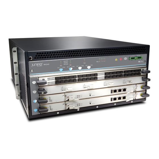
Upgrading MX240, MX480, and MX960
3D Universal Edge Router Fan Trays and
Power Supplies
December 2010
Part Number: 530-036423
Revision 02
Copyright © 2010, Juniper Networks, Inc.
This document describes the necessary steps to be taken to upgrade any Juniper Networks
MX Series 3D Universal Edge Router chassis to higher capacity cooling and higher capacity
power. Step-by-step descriptions are given for replacement of the various parts in the
chassis. All of these upgrades can be performed while the system is operational, but it
is important to follow the complete process through.
NOTE: Combinations of regular-capacity and high-capacity supplies and fan
trays are not supported outside of the upgrade window.
CAUTION: The router cannot be powered from AC and DC power supplies
simultaneously. The first type of power supply detected by the router when
initially powered on determines the type of power supply allowed by the
router. All installed power supplies of the other type are disabled by the router.
If you install a power supply of the other type while the router is operating,
the router disables the power supply and generates an alarm.
NOTE: Before upgrading, the MX Series router must be running Junos OS
Release 10.0 R1 or later to support high-capacity fan trays. Junos OS Release
10.0 R2 is required to support the MX240 and MX480 AC and DC high capacity
power supplies, and the MX960 AC high- capacity power supplies. Junos OS
Release 10.2 R1 is required to support the MX960 DC high-capacity power
supplies.
1
Advertisement
Table of Contents

Related Manuals for Juniper MX240 - UPGRADING


Summary of Contents for Juniper MX240 - UPGRADING
-
Page 1: Power Supplies
Part Number: 530-036423 Revision 02 This document describes the necessary steps to be taken to upgrade any Juniper Networks MX Series 3D Universal Edge Router chassis to higher capacity cooling and higher capacity power. Step-by-step descriptions are given for replacement of the various parts in the chassis. -
Page 2: Table Of Contents
Switch ............17 Copyright © 2010, Juniper Networks, Inc. - Page 3 Revision History ........... . 34 Copyright © 2010, Juniper Networks, Inc.
-
Page 4: Fan Tray Upgrade Overview
Release 10.0 R1 or later to support high-capacity fan trays. NOTE: To prevent overheating, install the replacement fan tray immediately after removing the existing fan tray. Figure 1: MX960 High-Capacity Fan Tray Figure 2: MX480 High-Capacity Fan Tray Copyright © 2010, Juniper Networks, Inc. -
Page 5: Replacing The Mx240 Fan Tray
WARNING: To avoid injury, keep tools and your fingers away from the fans as you slide the fan tray out of the chassis. The fans might still be spinning. NOTE: To prevent overheating, install the replacement fan tray immediately after removing the existing fan tray. Copyright © 2010, Juniper Networks, Inc. - Page 6 "this side up" label on the top surface of the fan tray. Tighten the captive screws on the fan tray faceplate to secure it in the chassis. Figure 5: Reinstalling a Fan Tray Copyright © 2010, Juniper Networks, Inc.
-
Page 7: Replacing The Mx480 Fan Tray
The fans might still be spinning. NOTE: To prevent overheating, install the replacement fan tray immediately after removing the existing fan tray. Figure 6: Removing the Fan Tray Copyright © 2010, Juniper Networks, Inc. -
Page 8: Replacing The Mx960 Fan Trays
ESD points on the chassis. Loosen the captive screw on each side of the fan tray faceplate. Grasp both sides of the fan tray and pull it out approximately 1 to 3 inches. Copyright © 2010, Juniper Networks, Inc. - Page 9 ESD points on the chassis. Grasp the fan tray on each side, and insert it straight into the chassis. Note the correct orientation by the "this side up" label on the top surface of the fan tray. Copyright © 2010, Juniper Networks, Inc.
- Page 10 Tighten the captive screws on each side of the fan tray faceplate to secure it in the chassis. Lower the standard cable manager back into position, if necessary. Figure 9: Installing an Upper Fan Tray Copyright © 2010, Juniper Networks, Inc.
-
Page 11: Upgrading The Mx960 Air Filter Tray
CAUTION: Always keep the air filter in place while the router is operating, except during replacement. Because the fans are very powerful, they could pull small bits of wire or other materials into the router through the unfiltered air intake. This could damage the router components. Copyright © 2010, Juniper Networks, Inc. -
Page 12: Installing The Mx960 High-Capacity Tray And Filter
Attach an electrostatic discharge (ESD) grounding strap to your bare wrist, and connect the strap to one of the ESD points on the chassis. Ensure that the air filter is right side up. Place the air filter into the air filter tray. Copyright © 2010, Juniper Networks, Inc. -
Page 13: Fan Tray Power Requirements
The minimum number of power supplies must be present in the router at all times. Table 2: Minimum Required Number of Power Supplies Router Model Configuration Minimum Required Number of Power Supplies MX240 AC – high line Copyright © 2010, Juniper Networks, Inc. -
Page 14: Upgrading The Mx240 And Mx480 Ac Power Supplies
If you remove a power supply, you must install a replacement power supply or a blank panel shortly after the removal. NOTE: After powering off a power supply, wait at least 60 seconds before turning it back on. Copyright © 2010, Juniper Networks, Inc. -
Page 15: Installing The Mx240 And Mx480 Ac High-Capacity Power Supplies
) position and observe the status LEDs on the power supply faceplate. If the power supply is correctly installed and functioning normally, the LEDs light AC OK DC OK steadily and the LED is not lit. PS FAIL Copyright © 2010, Juniper Networks, Inc. -
Page 16: Upgrading The Mx240 And Mx480 Dc Power Supplies
If you remove a power supply, you must install a replacement power supply or a blank panel shortly after the removal. NOTE: After powering off a power supply, wait at least 60 seconds before turning it back on. Copyright © 2010, Juniper Networks, Inc. -
Page 17: Switch
NOTE: Do not set the input mode switch if the power supply is installed in the chassis. If the power supply is already installed, you must remove it before setting the input mode switch. Copyright © 2010, Juniper Networks, Inc. - Page 18 CAUTION: Do not use a pencil, because fragments can break off and cause damage to the power supply. Rotate the metal cover over the input mode switch, and use a screwdriver to tighten the captive screw. Copyright © 2010, Juniper Networks, Inc.
-
Page 19: Installing The Mx240 And Mx480 Dc High-Capacity Power Supplies
The nut should be able to spin freely with your fingers when it is first placed onto the terminal stud. Applying installation torque to the nut when improperly threaded may result in damage to the terminal stud. Copyright © 2010, Juniper Networks, Inc. - Page 20 On each of the DC power supplies, switch the DC circuit breaker to the center position before moving it to the on ( ) position. — NOTE: The circuit breaker may bounce back to the off ( ) position if you move the breaker too quickly. Copyright © 2010, Juniper Networks, Inc.
- Page 21 NOTE: If more than one power supply is being installed, turn on all power supplies at the same time. NOTE: An SCB must be present for the LED to go on. PWR OK Figure 16: Installing a DC Power Supply in the Router Copyright © 2010, Juniper Networks, Inc.
-
Page 22: Upgrading The Mx960 Ac Power Supplies Overview
Remember to turn on both switches while upgrading the MX960 AC power supply (the one on the power supply and the one on the Power Distribution Module [PDM]). Continue by removing an adjacent existing power supply and replacing it with a high-capacity power supply. Copyright © 2010, Juniper Networks, Inc. -
Page 23: Removing The Mx960 Ac Power Supplies
Let go of the locking pin in the release lever. Ensure that the pin is seated inside the corresponding hole in the chassis. Pull the power supply straight out of the chassis. Copyright © 2010, Juniper Networks, Inc. - Page 24 Upgrading MX240, MX480, and MX960 3D Universal Edge Router Power Supplies and Fan Trays WARNING: Do not touch the power connector on the top of the power supply. It can contain dangerous voltages. Figure 19: Removing an MX960 AC Power Supply Copyright © 2010, Juniper Networks, Inc.
-
Page 25: Installing The Mx960 Ac High-Capacity Power Supplies
LEDs on the power supply faceplate. If the power supply is correctly installed and functioning normally, the AC OK DC OK LEDs light steadily, and the LED is not lit. PS FAIL Copyright © 2010, Juniper Networks, Inc. - Page 26 Air exhaust AC Power supplies Power supply ejectors Protective earthing ESD point NOTE: The MX960 DC power supplies protrude approximately 2 inches from the back of the chassis. See Figure 21 on page 27. Copyright © 2010, Juniper Networks, Inc.
-
Page 27: Upgrading The Mx960 Dc Power Supplies Overview
Move the input mode switch to position 0 for one feed or position 1 for two feeds. NOTE: For a fully redundant configuration in two-feed mode, 8 feeds are required. For a non-redundant configuration, 4 feeds are required. Copyright © 2010, Juniper Networks, Inc. -
Page 28: Removing An Mx960 Dc Power Supply
CAUTION: To maintain proper cooling and prevent thermal shutdown of the operating power supply unit, each power supply slot must contain either a Copyright © 2010, Juniper Networks, Inc. - Page 29 Let go of the locking pin in the release lever. Ensure that the pin is seated inside the corresponding hole in the chassis. Pull the power supply straight out of the chassis. WARNING: Do not touch the power connector on the top of the power supply. It can contain dangerous voltages. Copyright © 2010, Juniper Networks, Inc.
-
Page 30: Installing The Mx960 Dc High-Capacity Power Supplies
Attach an electrostatic discharge (ESD) grounding strap to your bare wrist, and connect the strap to one of the ESD points on the chassis. Move the switch on the power supply faceplate to the off ( ) position. Copyright © 2010, Juniper Networks, Inc. - Page 31 36 lb-in. (4.0 Nm). The terminal studs may be damaged if excessive torque is applied. Use only a torque-controlled driver or socket wrench to tighten nuts on the DC power supply terminal studs. Copyright © 2010, Juniper Networks, Inc.
- Page 32 On each of the DC power supplies, move the switch to the on ( ) position. NOTE: The switch may bounce back to the off ( ) position if you move the breaker too quickly. Verify that the LED is lit steadily. DC OK Copyright © 2010, Juniper Networks, Inc.
-
Page 33: Junos Documentation And Release Notes
JUNOS Release Notes. ® To obtain the most current version of all Juniper Networks technical documentation, see the product documentation page on the Juniper Networks website at http://www.juniper.net/techpubs/ Requesting Technical Support Technical product support is available through the Juniper Networks Technical Assistance Center (JTAC). -
Page 34: Self-Help Online Tools And Resources
Juniper Networks, Junos, Steel-Belted Radius, NetScreen, and ScreenOS are registered trademarks of Juniper Networks, Inc. in the United States and other countries. The Juniper Networks Logo, the Junos logo, and JunosE are trademarks of Juniper Networks, Inc. All other trademarks, service marks, registered trademarks, or registered service marks are the property of their respective owners. - Page 35 Products made or sold by Juniper Networks or components thereof might be covered by one or more of the following patents that are owned by or licensed to Juniper Networks: U.S. Patent Nos. 5,473,599, 5,905,725, 5,909,440, 6,192,051, 6,333,650, 6,359,479, 6,406,312, 6,429,706, 6,459,579, 6,493,347, 6,538,518, 6,538,899, 6,552,918, 6,567,902, 6,578,186, and 6,590,785.