Sign In
Upload
Manuals
Brands
Toshiba Manuals
Copier
e-studio550
Toshiba e-studio550 Manuals
Manuals and User Guides for Toshiba e-studio550. We have
4
Toshiba e-studio550 manuals available for free PDF download: Service Manual, Service Handbook, Operator's Manual
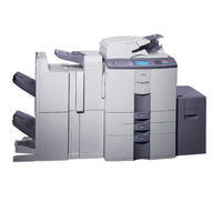
Toshiba e-studio550 Service Handbook (314 pages)
Digital Plain paper Copier
Brand:
Toshiba
| Category:
Copier
| Size: 7.65 MB
Table of Contents
General Precautions Regarding the Installation
2
Service of Machines
2
Transportation/Installation
2
Cautionary Labels
3
Main Service Parts for Safety
3
Precautions against Static Electricity
3
Table of Contents
5
1 Specifications / Accessories / Options / Supplies
8
Specifications
8
System Copy Speed
9
Copy Paper
10
Accessories
12
Machine Version
12
Options
13
Supplies
13
System List
14
2 Error Codes and Self-Diagnosis
15
Control Panel Check Mode
22
Operation Procedure
22
Self-Diagnosis Modes
22
List Printing Mode
23
PM Support Mode
23
Input Check (Test Mode 03)
24
Output Check (Test Mode 03)
30
Test Print Mode (04)
33
Adjustment Mode (05)
34
Setting Mode (08)
45
State Transition Diagram of Self-Diagnosis Modes
23
3 Adjustment
61
Hard Disk Formatting
61
Adjustment of Auto-Toner Sensor
62
Dimensional Adjustment of Copied Image
64
Overview
64
Paper Alignment
64
Procedure to Input the Adjustment Values
65
Paper Alignment
66
Printer Related Adjustment
67
Reproduction Ratio Adjustment of the Secondary Scanning Direction
68
Adjustment for Long-Sized Paper
69
Adjustment for Short-Sized Paper
69
Order of Distances to be Adjusted
71
Scanner Related Adjustment
72
Image Distortion Adjustment
72
Reproduction Ratio Adjustment of the Primary Scanning Direction
73
Image Position Adjustment of the Primary Scanning Direction
74
Top Margin
77
Right Margin
77
Bottom Margin
78
Image Quality Adjustment
79
Image Density for Copier
79
Keys Used in the Operation
79
Sharpness Adjustment for Copier
80
Gamma Slope Adjustment
80
Setting for Range Correction for Copier
81
Adjustment of Background Peak for Range Correction for Copier
81
Adjustment of Blurred/Thin Spotted Text
82
Adjustment of Image Density for Printer
82
Developer Bias
83
High-Voltage Adjustment
83
Main Charger Grid Bias
83
Note for Adjustment
84
Operation
84
Precautions
84
Adjustment of Scanning Section
85
Carriages
85
Installing the Carriage Wire
85
Adjustment of the Positions of the Carriages-1 and -2
86
Winding the Wire Around the Pulleys
87
Wind the Wire Around the Wire Pulley
87
Lens Unit
89
Replacment of the Lens Unit
89
Adjustment of the Magnification Ratio of the Lens
90
Adjustment of Paper Feeding System
92
Sheet Sideways Deviation Caused by Paper Feeding
92
Tandem LCF
93
Adjustment of Developer Unit
94
Doctor-Sleeve Gap
94
Drum-Sleeve Gap
94
Pole Position of the Developer Sleeve
94
Adjustment of Fuser Roller Pressure
95
Adjustment of Fuser Inlet Guide
96
Setting of Fuser Roller Temperature
96
High-Fusing Mode
97
Level up at 1St Printing
97
Level up at Continuous Printing
97
Adjustment of Exit/Reversal Unit
98
Adjustment of Sideways Deviation at Reverse Discharging
98
Adjustment of Reversing Automatic Document Feeder
99
Installing of the RADF Unit
99
Skew Adjustment
100
Adjustment of Solenoid
101
Disengagement Solenoid
101
Small Original Exit Solenoid
101
Large Original Exit Solenoid
101
Adjustment of RADF Open/Close Switch
102
Adjustment of RADF Height
102
Key Copy Counter (MU-8, MU-10)
103
PM Support Mode
105
4 Preventive Maintenance (Pm)
105
General Description
105
Operational Flow and Operational Screen
105
Main Screen
106
Operational Screen
106
Clear Screen
107
Sub Screen
107
Access Tree
108
General Descriptions for PM Procedure
109
Operational Items in Overhauling
109
Preparation
109
Preventive Maintenance Checklist
109
Preventive Maintenance Checklist
110
Front Side
114
Rear Side
115
Automatic Document Feeder
116
Original Glass
117
Pickup Roller and Feed Roller
117
Separation Roller
117
Slit Glass
117
Cleaner Unit / Toner Adhesion Amount Sensor / Drum Shaft Bearing
118
Drive Gears in the Paper Feeding Section
118
Main Charger Case/Main Charger Wire
118
Drum Cleaning Blade / Drum Creaning Brush
119
Recovery Blade
119
Separation Fingers for the Drum
119
Toner Transport Auger Drive Section
119
Mixer Shaft
120
Oil Seal
120
Transfer Belt Cleaning Bush/Flicker Periphery
121
Transfer Belt Power Supply Roller
121
Upper Separation Finger
121
Whole Toner Recycle Unit
121
Cleaning Web/Web Pushing Roller
122
Thermistor
122
PM Kit
123
Jig List
124
Precautions for Storing and Handling Supplies
125
Checking and Cleaning of OPC Drum
125
OPC Drum
125
Installation of Copier and Storage of Drum
126
Cleaning the Drum
126
Scratches on OPC Drum Surface
126
Collecting Used OPC Drums
126
Checking and Cleaning of Drum Cleaning Blade and Transfer Belt Cleaning Blade
126
Handling of Drum Cleaning Brush and Transfer Belt Cleaning Brush
127
Handling of Transfer Belt
127
Checking and Cleaning of Fuser Roller and Pressure Roller
127
Cleaning Procedure
127
Defective Cleaning and Countermeasures
128
Precaution When Installing Cleaning Web
128
Checking and Replacing of Cleaning Web and Cleaning Rollers (Felt, Metal)
128
Diagnosis and Prescription for each Error Code and Phenomenum
129
Paper Transport Jam
129
Paper Remaining Inside the Copier at Power on
130
Is the Sensor in the Jamming Area Working?
130
Jam Caused by an Abnormal HDD
131
Is the Registration Sensor Working?
131
Paper Fed from the 2Nd Cassette Not Reaching the Registration Sensor
132
Paper Fed from the 3Rd Cassette Not Reaching the Registration Sensor
132
Paper Fed from the 4Th Cassette Not Reaching the Registration Sensor
132
Paper Fed from the Tandem LCF Not Reaching the Registration Sensor
132
External LCF Transport Jam
133
Paper Left on the Transport Path
141
Paper Misfeeding
142
Bypass Misfeeding
143
1St Cassette Misfeeding
144
2Nd Cassette Misfeeding
145
3Rd Cassette Misfeeding
146
4Th Cassette Misfeeding
147
LCF Misfeeding
148
Is the LCF Transport Motor Working?
148
Cover Open Jam
149
Front Cover Opened During Printing
149
Feed Cover Opened During Printing
149
LCF Opened During Printing
150
Is the LCF Open?
150
Bypass Feed Unit Cover Opened During Printing
150
Is the Bypass Feed Unit Cover Open?
150
Jams at Exit/Reverse Section and Other Tronsport Jams
152
Leading Edge of Paper Not Reaching the Reverse Sensor 2
152
Leading Edge of Paper Not Reaching the Transport Sensor 1
153
Leading Edge of Paper Not Reaching the Transport Sensor 2
154
Leading Edge of Paper Not Reaching the Transport Sensor 3
155
Paper Remaining on the Transport Path When CRUN Is off
156
Relation between the Jamming Area and the Corresponding Sensors
156
Leading Edge of Paper Not Reaching the Reverse Sensor 1
157
Trailing Edge of Paper Not Passing the Reverse Sensor
158
Leading Edge of Paper Not Reaching the Exit Sensor
159
Trailing Edge of Paper Not Passing the Exit Sensor
160
Original Jam in RADF
161
Original Feeding Jam
161
Original Transport Jam
161
Original Discharging Jam
161
Short-Sized Original Exit Jam
162
Transport Jam at Scanning Section
162
RADF Opened During Original Feeding
163
RADF Opened During Original Transporting
163
RADF Opened During Large-Sized Original Discharging
163
RADF Opened During Small-Sized Original Reversing
163
Jam Access Cover Opened During Original Feeding
164
Jam Access Cover Opened During Original Transporting
164
Jam Access Cover Opened During Large-Sized Original Discharging
164
Jam Access Cover Opened During Small-Sized Original Reversing
164
Paper Jam in Finisher
165
Punching Jam
165
Finisher Paper Transport Delay Jam
165
Finisher Paper Transport Stop Jam
166
Paper Remaining Inside the Finisher at Power on
167
Finisher Front Door Opened During Printing
168
Finisher Stapling Jam
170
Finisher Early Arrival Jam
171
Saddle Stitcher Stapling Jam
172
Saddle Stitcher Door Opened During Printing
173
Paper Remaining at the Saddle Stitcher at Power on
174
Saddle Stitcher Transport Stop Jam
175
Saddle Stitcher Transport Delay Jam
176
Print End Command Time-Out Jam
176
Receiving Time Time-Out Jam
176
Ready Time Time-Out Jam
177
Inserter Feeding Delay Jam
178
Inserter Feeding Stop Jam
178
Inserter Reverse Path Delay Jam 1
179
Inserter Reverse Path Stop Jam 1
179
Inserter Reverse Path Delay Jam 2
179
Inserter Reverse Path Stop Jam 2
179
Paper Remaining at the Inserter When the Power Is on
180
Inserter Size Difference Jam
180
Inserter Feeding Jam
180
Paper Feeding System Related Service Call
181
Abnormal Feed Motor
181
Abnormal Tandem LCF Tray-Up Motor
183
Abnormal Tandem LCF End Fense Motor
184
External LCF Tray Motor Driving Abnormally
185
Process System Related Service Call
186
Main Charger Wire Cleaning Operating Abnormally
186
Transfer Belt Operating Abnormally
186
Cleaning Brush Drive Motor Driving Abnormally
186
Toner Bag Full
187
Scanning System Related Service Call
188
Peak Detection Error
188
Does the Exposure Lamp Light?
188
Carriage Home Position Sensor Not Going off Within a Fixed Time
189
Carriage Home Position Sensor Not Going on Within a Fixed Time
189
Fuser Unit Related Service Call
190
Abnormal Thermistor or Heater at Power on
190
Check the IH Control Board and IH Coil
190
Check the LGC Board
190
Abnormal Thermistor after Abnormality Judgment
191
Abnormal Fuser after Abnormality Judgment
191
Clear the Status Counter
191
Check the Side Thermistor
191
Check the Pressure Roller Thermistor
192
Abnormal IH Power Voltage/Ih Initialization Error
193
IGBT High Temperature
194
Abnormal IH Circuit or Coil
194
Cleaning Web Finished
195
Abnormality at the Web Motor Signal Path
195
Communication System Related Service Call
196
RADF I/F Being Abnormal
196
Communication Error between the Main CPU and PFC-CPU
196
Communication Error between the Main CPU and IPC Board
196
Communication Error between the IPC Board and Finisher
197
Communication Error between the Main CPU and Laser CPU
197
Communication Error between SYS Board and LGC Board
198
Communication Error between SYS Board and SLG Board
198
ADF Related Service Call
199
EEPROM Initialization Error
199
Read Sensor Adjustment Error
200
Original Length Sensor Adjustment Error
201
Small Original Reverse Sensor Adjustment Error
201
Lifting Tray Motor Error
202
Is the Lifting Tray Lifted When Originals Are Set on the Feeding Tray?
202
Is Upper Limit Sensor Working Properly When Lifting Tray Is Lifted?
202
Large Original Exit Sensor Adjustment Error
203
Laser Optical Unit Related Service Call
204
Abnormal Polygonal Motor
204
Is the Polygonal Motor Rotating?
204
H-Sync Detection Error
204
Secondary Scanning Coarse Adjustment
205
Laser Power Adjustment Error
205
Laser Caliblation Error
205
Secondary Scanning Fine Adjustment Error
205
Sending Error of the Image Data from the SYS Board
206
Finisher Related Service Call
207
Is Second Feed Motor (M8) Rotating in Reverse at the Fixed Timing?
208
Is the Shutter Securely Attached to the Shutter Upper/Lower Bars?
208
Is the Shutter Open Sensor (PI5) Working Normally?
208
Abnormal Delivery Motor
209
Rotate the Delivery Motor by Hand. Does It Rotate Smoothly?
209
Is the Delivery Motor Clock Sensor (PI10) Working Normally?
209
Tray Lifting Motor Driving Abnormally
210
Is the Tray 1 Lifted/Lowered?
210
Is There any Abnormality at the Tray 1 Lifting Mechanism?
210
Is the Tray 2 Home Position Sensor Working Properly?
211
Is the Tray 2 Lifting Mechanism Working Properly?
211
Is the Tray 2 Lifted/Lowered?
211
Is There any Abnormality at the Tray 2 Lifting Mechanism?
211
Abnormal Alignment Motor
212
Abnormal Staple Motor
212
Is the Alignment Guide Home Position Sensor (PI6) Working Normally?
212
Is the Problem Solved by Replacing the Alignment Motor?
212
Abnormal Stapler Shift Motor
213
Abnormal Height Sensor
213
Is the Stapler Shift Home Position Sensor (PI7) Working Normally?
213
Is the Problem Solved by Replacing the Stapler Shift Motor?
213
Is the Problem Solved by Readjusting the DIP Switch?
214
Abnormal Backup RAM Data
215
Abnormal Saddle Stitcher Paper Pushing Plate Motor
215
Abnormal Saddle Stitcher Stitch Motor (Front)
217
Abnormal Saddle Stitcher Stitch Motor (Rear)
217
Abnormal Saddle Stitcher Alignment Motor
217
Is the Alignment Plate Home Position Sensor (PI5S) Working Normally?
217
Abnormal Saddle Stitcher Guide Motor
218
Abnormal Saddle Stitcher Paper Folding Motor
218
Is the Guide Home Position Sensor (PI13S) Working Normally?
218
Is the Guide Motor (M3S) Operating at the Fixed Timing?
218
Abnormal Saddle Stitcher Paper Positioning Plate Motor
219
Saddle Stitcher Sensor Connector Connection Error
219
Is the Wiring between the Sensor and the Saddle Stitcher Correct?
219
Abnormal Saddle Stitcher Microswitch
221
Is the Switch Actuator for the Inlet Door Working Properly?
221
Is the Inlet Cover Switch (MS1S) Working Normally?
221
Is the Switch Actuator for the Front Door Working Properly?
222
Is the Front Cover Switch (MS2S) Working Normally?
222
Communication Error between Finisher and Saddle Stitcher
223
Abnormal Swing Motor
224
Is the Safety Zone Switch (MS3) Working Normally?
224
Is the Safety Zone Switch (MS3) Correctly Pressed?
224
Is the Swing Motor Clock Sensor (PI20) Working Normally?
225
Abnormal Horizontal Registration Motor
226
Abnormal Punch Motor
227
Abnormal Punch Unit Backup RAM Data
227
Communication Error between the Inserter and Finisher
228
Abnormal Inserter EEPROM
228
Abnormal Inserter Fan
228
Service Call for Others
229
Abnormal Main CPU
229
Troubleshooting for Image Quality Control
230
Check the Control Status of the Image Quality Control(05-291)
230
Corrective Action for Pattern Error
230
Is the Developer Unit Inserted Completely and Locked?
230
Corrective Action for Sensor Error
231
If the Output Value Is above 819
231
If the Output Value Is Less than (Value for 08-814)X4
231
Is the Window of the Image Quality Sensor Tainted?
231
Troubleshooting for Surface Potential Control
233
Check the Control Status of the Surface Potential Sensor (05-242)
233
Procedure of the “Surface Potential Sensor Control Check”
234
Troubleshooting for Image
235
Abnormality of Image Density/Gray Balance
235
Background Fogging
236
Moire
238
Lack of Sharpness
238
Toner Offset
239
Blurred Image
240
Poor Fusing
241
Blank Copy
242
Solid Copy
243
White Banding (in the Feeding Direction)
244
White Banding (at Right Angle with the Feeding Direction)
245
Skew (Inclined Image)
246
Black Banding (in the Feeding Direction)
247
Black Banding (at Right Angle with the Feeding Direction)
248
White Spots
249
Poor Image Transfer
251
Uneven Image Density
252
Faded Image (Low Density, Abnormal Gray Balance)
253
Caution for Correction
254
Toner Density Correcting Method
254
Image Dislocation in Feeding Direction
255
Jittering Image
256
Poor Cleaning
257
Cleaning Blade
258
Toner Recovery Auger
258
Recycle Unit
258
Uneven Light Distribution
259
Blotched Image
260
5 Troubleshooting
129
6 Firmware Updating
261
Software Installing for Firmware Updating
262
Requirements
262
Software Requirements for PC
262
DTE-DTE Connection
262
Outline
262
Protocol Specifications between the PC and SYS Board
263
Dial-Up Network Function
264
Virtual Modem
264
Installation of the Virtual Modem
264
Installing Dial-Up Networking
268
Setting of Dial-Up Network
270
Software Installing for FTP Server
274
Operation Procedure in [3][9] Mode
278
Outline
278
Preparation
278
Software Installation
278
Connection between the SYS Board and PC
279
New File
279
Updating Procedure
280
Recovery Mode
286
Assist Mode
287
Clear Nvram Flags
287
Format a Language Partition
287
Display
288
Firmware Version up Mode
288
Firmware Updating with Download Jig
292
System Firmware
293
ROM Type
293
ROM for Application Downloading
293
ROM for UI Data Downloading
293
Downloading Procedure
294
Connect the Jig and Perform Downloading
294
Confirmation of the Downloaded Data
296
Confirmation for Application Downloading
296
Confirmation for UI Data Downloading
296
Screens Displayed During the Download
297
Application Downloading
297
UI Data Downloading
298
Engine Firmware
299
Jig Board
299
Downloading
300
Printer ROM, PFC ROM/LGC Board
300
Scanner ROM/SLG Board
300
Laser ROM/PLG Board
301
RADF ROM/RADF Board
301
Inserter Rom/Inserter Main Board
302
Output Channel
303
7 Power Supply Unit
303
Fuse
307
8 Wire Harness Connection Diagrams
309
100V Series
310
115V or 120V Series
310
200V Series
310
AC Diagram
310
DC Diagram
312
Reversing Automatic Original Feeder
312
Advertisement
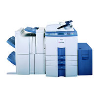
toshiba e-studio550 Service Manual (346 pages)
DIGITAL PLAIN PAPER COPIER
Brand:
toshiba
| Category:
Copier
| Size: 14.11 MB
Table of Contents
Table of Contents
15
Exposure Lamp
3
Specifications
6
25~200% When Using the RADF
8
System List
12
Outline of the Machine
13
Sectional View
14
Table of Contents
15
Electric Parts Layout
18
Rear Side
25
Symbols and Functions of Various Components
29
Symbols and Functions of Radf Various Components
37
System Block Layout
39
Copy Process
44
Details of Copy Process
46
General Operation
56
Control Panel
71
Control Panel and Display Panel
72
Items Shown on Display Panel
73
Display During Normal Copying
74
Display in Abnormal Condition
76
Relation between Copier State and Operator's Action
78
Dot Matrix Lcd Circuit
79
Led Display Circuit
81
Reflector
85
Scanner Control PC Board
95
Image Processing
104
Drum
105
8. Laser Optical Unit
113
General Description
114
Laser Optical Unit
114
Laser Diode
116
Structure
116
Disassembly and Replacement
121
Paper Feeding System
123
Drum Thermistor
163
Image Quality Control
165
Developer Unit
173
13. Transfer/Transport Unit
195
General Description
196
Operation
196
Transfer/Transport Unit
196
Functions
197
Disassembly and Replacement
199
Fuser Unit
206
Drive System
240
Timing Chart
294
Power Supply Unit
329
Operation of DC Output Circuits
330
Output Channel
331
Charger Wire Cleaner
334
Configuration of Power Supply Unit
336
Power Supply Sequence
337
Pc Boards
339
Toshiba e-studio550 Operator's Manual (179 pages)
Digital Plain Paper copier Copying functions
Brand:
Toshiba
| Category:
Copier
| Size: 6.29 MB
Table of Contents
Toshiba Quality Is Second to None
4
Preface
6
Features of the E-STUDIO550/650/810
7
Table of Contents
8
Table of Contents
9
Disclaimer Notice
11
Precautions
12
Installation
12
General Precautions
13
Before Making Copies
16
Description of the Digital Copier and the Optional Equipment
17
Main Components
17
Optional Equipment
18
Control Panel
19
Touch Panel
21
Turning on the Power Switch
23
Turning on the Power Switch/Auto Job Start
23
Controlling the Use of the Copier with Department Codes
24
Controlling the Use of the Copier with the Optional Key Copy Counters
25
How to Make Copies
26
General Copying Procedures
27
Setting Copy Paper
29
Acceptable Copy Paper Types and Sizes
29
Handling and Storing Paper
30
Changing the Paper Size of the Drawer/Setting the Drawer for Special Uses
31
Setting Originals
34
Acceptable Original Types and Sizes
34
When Placing an Original on the Glass
35
When Using the Reversing Automatic Document Feeder
36
Auto Job Start (Job Preset)
38
Interrupt Copying
39
Stopping the Copy Operation
40
Deleting or Changing Order of Pending Jobs
41
Setting of Basic Copy Modes
44
Paper Selection
45
Automatic Paper Selection (APS)
45
Manual Paper Selection
46
Reduction and Enlargement Copying
47
Duplex Copying (1-Sided, 2-Sided, Book-Type)
50
Copy Density Adjustment
54
Selecting Original Mode
56
Quick Access Menu
57
Using the Editing Functions
58
Image Shift
59
Edge Erase
61
Dual-Page
62
X-Y Zoom
64
Image Editing
65
Trimming/Masking
65
Mirror Image
67
Negative/Positive Reversal
68
In 1 /4 in 1
69
Copying with the Annotation
71
Page Numbering Copying
72
Magazine Sort (from the Editing Menu)
73
Cover Copying
75
Sheet Insertion Copying
77
Tab Paper Mode
79
Document Storage
85
Overlay
87
Sharpness Adjustment
90
Direction of Duplex Images (Rotation)
91
Using the Special Functions
93
Continuous Original Feeding / Single Original Feeding
93
Mixed-Sized Originals
95
Job Memory
96
Bypass Copying
99
Bypass Copying on Standard Size Paper
101
Bypass Copying on Non-Standard Size Paper
102
Weekly Timer
104
Setting the "OTHER" Size Key
105
Setting the Date and Time
106
Setting the Automatic Energy Save Mode
107
Setting the Automatic Off-Mode
108
Switching Languages
109
Department Codes
110
Department Code
112
Entering Letters
119
Selecting Finishing Modes (Using the Optional Finishers and the Inserter)
123
Finishing Modes and Finishers (Optional)
123
Sort/Group Copying
124
Staple Sorting (Optional)
125
Magazine Sort & Saddle Stitch Mode (Booklet Mode) (Optional)
127
Hole Punch Mode (Optional)
129
Inserter Mode (Optional)
130
Setting the Inserter
131
Using Only Staple and Hole Punch
134
7 When the Graphic Symbols Flash on the Touch Panel
137
Description of the Flashing Graphic Symbols
137
Add Paper Symbol
138
Adding Paper to the Drawers
138
Adding Paper to the Tandem LCF (Large Capacity Feeder)
139
Adding Paper to the External LCF (Large Capacity Feeder)(Optional)
140
Replace Toner Cartridge Symbol
143
Type of Originals
143
Clear Paper Symbol
144
Reversing Automatic Document Feeder
144
Inside of the Copier
144
Bypass Guide
144
External LCF (Optional)
144
Inserter (Optional)
144
Hole Punch Unit (Optional)
144
Finisher (Optional)
144
Saddle Stitch Unit (Optional)
155
Adding Staples (Optional)
156
Removing Jammed Staples (Optional)
159
Disposing of Accumulated Punched Paper Bits (Optional)
162
Call Service Symbol/Periodic Maintenance Message
163
Call Service Symbol / Periodic Maintenance Message
163
Maintenance
164
Daily Inspection
164
Daily Inspection
165
Simple Troubleshooting
166
Specifications & Options
169
E-STUDIO550/650/810 Specifications
169
Specifications of Options
173
Packing List
173
Index
174
Periodic Maintenance
178
Advertisement
Toshiba e-studio550 Operator's Manual (148 pages)
Brand:
Toshiba
| Category:
Copier
| Size: 1.07 MB
Table of Contents
Limited Warranty and Disclaimer
3
Proprietary Rights
3
Software License Agreement
3
Table of Contents
6
I I I I I Introduction
11
About the Documentation
12
About this Guide
12
About Other Manuals
12
I I I I I Preparing for GA-1140 Setup
13
About Setup and Administration
14
Easy Setup Flow
15
Setup Flow for Windows Environments
15
For Parallel Printing
15
For SMB Printing
15
For LPR Printing
15
For IPP Printing
16
For Novell Printing
16
Setup Flow for Mac os Environments
17
How to Setup from Touch Panel Display
18
Accessing Setting Menu
20
Switching On-Line/Off-Line
22
How to Setup from Topaccess
23
Accessing Topaccess for Administrator
25
Connecting to the Parallel Port
26
Connecting to the Network
27
I I I I I Setting up the Network Servers
29
About Network Servers Setup
30
Windows NT 4.0/2000 Server Setup
31
Configuring a Windows NT 4.0/2000 Server
32
Adding the GA-1140 to the TCP/IP Network
32
Installing the GA-1140 as a Shared Printer
33
Configuring Clients of a Windows NT 4.0 Server
34
Netware Server Setup
35
Netware 5.X Server Setup with NDPS
35
Configuring a Netware 5.X Server with NDPS
36
Netware 3.X or 4.X Server Setup
37
Configuring a Netware 4.X Server with NDS
38
Configuring a Netware 4.X with Bindery Emulation
39
Configuring a Netware 3.X with Bindery Emulation
41
I I I I I Setting up the Network Setup Options
43
Setting up the Port Options
44
Setting up the Ethernet Options
44
Setting up from Touch Panel Display
44
Setting up from Topaccess
45
Setting up the Parallel Port Options
46
Setting up from Touch Panel Display
46
Setting up from Topaccess
47
Setting up the Protocols
48
Setting up the TCP/IP Options
48
Setting up from Touch Panel Display
49
Setting up from Topaccess
51
Setting up the IPX/SPX Options
52
Setting up from Touch Panel Display
52
Setting up from Topaccess
53
Setting up the Appletalk Options
54
Setting up from Touch Panel Display
54
Setting up from Topaccess
55
Setting up the Print Services
56
Setting up the Netware Options
56
Setting up from Touch Panel Display
56
Setting up from Topaccess
59
Setting up the Windows Printing Service
61
Setting up from Touch Panel Display
61
Setting up from Topaccess
63
Setting up the LPD Printing Service
65
Setting up from Touch Panel Display
65
Setting up from Topaccess
66
I I I I I Setting up the Printer Setup Options
70
Setting up the Printer Setup Options
70
Setting up the Printer Default Options
70
Setting up from Touch Panel Display
70
Setting up from Topaccess
78
Setting up the Emulation Options
81
Setting up from Touch Panel Display
81
Setting up from Topaccess
82
Setting up the PCL Options
84
Setting up from Touch Panel Display
84
Setting up from Topaccess
87
Setting up the PS Options
89
Setting up from Touch Panel Display
89
Setting up from Topaccess
90
Setting up the Queue Options
92
Setting up from Topaccess
92
I I I I I Setting up the Topaccess Setup Options
96
Setting up the Topaccess Setup Options
96
Setting up the Topaccess Options
96
Setting up from Touch Panel Display
96
Setting up from Topaccess
97
Setting up the Job Log Options
100
Setting up from Topaccess
100
Setting up the Language Options
102
Setting up from Topaccess
102
I I I I I Administrative Functions
103
Administrative Functions on Touch Panel Display
104
Printing Test Pages
105
Printing a Current Job Forcibly
107
Deleting a Current Job Forcibly
109
Resetting the GA-1140
111
Restarting the GA-1140
113
Clearing the Server
115
Setting Administrator Password
117
Administrative Functions on Topaccess
119
Displaying the Print Log
120
Printing Test Pages
121
Setting Administrator Password
123
Changing the TOSHIBA MFP Logo Web Link
125
Restoring the Factory Defaults
126
Resetting the GA-1140
127
Restarting the GA-1140
128
Clearing the Server
129
Displaying and Managing the Counter
130
Displaying the Drawer Counter
130
I I I I I Troubleshooting
131
Maintaining Optimal Performance
132
Troubleshooting During Setup
133
Runtime Error Messages
134
Touch Panel Display Messages
134
Topaccess Messages
134
I I I I I Appendix
137
Appendix Printme Activation Guide
138
DNS Setup Options
138
Printme Setup Options
139
Activating Printme Services
140
Default Setting List
142
Default Setting List for Printer Function
142
Topaccess Setting
142
Printer Setting
143
Default Setting List for Network Function
144
Port Setting
144
TCP/IP Setting
144
IPX/SPX Setting
144
Netware Setting
145
Appletalk Setting
146
Other Setting
146
Advertisement
Related Products
Toshiba e-STUDIO28
Toshiba e-studio15
Toshiba e-studio650
Toshiba e-STUDIO211c
Toshiba e-studio 12
Toshiba e-studio 15
Toshiba e-STUDIO810 GA-1140
Toshiba e-studio2309a
Toshiba e-STUDIO5500c
Toshiba E-STUDIO5506AC
Toshiba Categories
Laptop
Air Conditioner
TV
LCD TV
All in One Printer
More Toshiba Manuals
Login
Sign In
OR
Sign in with Facebook
Sign in with Google
Upload manual
Upload from disk
Upload from URL