Sign In
Upload
Manuals
Brands
Mitsubishi Electric Manuals
Inverter
FR-A500 Series
Mitsubishi Electric FR-A500 Series Manuals
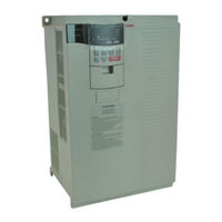
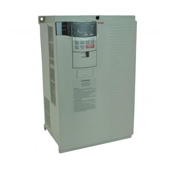
Manuals and User Guides for Mitsubishi Electric FR-A500 Series. We have
6
Mitsubishi Electric FR-A500 Series manuals available for free PDF download: Technical Manual, Instruction Manual
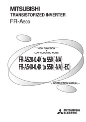
Mitsubishi Electric FR-A500 Series Instruction Manual (257 pages)
TRANSISTORIZED INVERTER
Brand:
Mitsubishi Electric
| Category:
Inverter
| Size: 5.7 MB
Table of Contents
Instruction Manual
1
Table of Contents
5
Chapter 1 Outline
10
Outline
10
Pre-Operation Information
11
Precautions for Operation
11
Basic Configuration
12
Control
12
Structure
13
Appearance and Structure
13
Removal and Reinstallation of the Front Cover
14
Removal and Reinstallation of the Operation Panel
16
Chapter 2 Installation and Wiring
18
Installation
19
Instructions for Installation
19
Wiring
21
Terminal Connection Diagram
21
Wiring of the Main Circuit
24
Connection Procedure
29
Wiring of the Control Circuit
30
Connection to the PU Connector
34
Connection of Stand-Alone Option Units
37
Design Information
42
2.3 Other Wiring
43
Power Supply Harmonics
43
Inverter-Generated Noises and Their Reduction Techniques
43
Leakage Currents and Countermeasures
46
Inverter-Driven 400V Class Motor
47
Peripheral Devices
48
Instructions for UL and Cul
51
Instructions for Compliance with the European Directives
52
Earthing (EC Version)
54
Chapter 3 Operation/Control
56
Pre-Operation Information
57
Devices and Parts to be Prepared for Operation
57
Power on
59
Operation Panel
60
Names and Functions of the Operation Panel (FR-DU04)
60
Monitor Display Changed by Pressing the Key
61
Monitoring
61
Frequency Setting
61
Parameter Setting Method
62
Operation Mode
63
Help Mode
63
Copy Mode
65
Operation
66
Pre-Operation Checks
66
External Operation Mode (Operation Using External Input Signals)
67
PU Operation Mode (Operation Using the Operation Panel (FR-DU04))
68
Combined Operation Mode (Operation Using the External Input Signals and PU)
69
Operation/Control
56
Chapter 4 Parameters
70
Parameter Lists
71
List of Parameters Classified by Purpose of Use
78
Parameters Recommended to be Set by the User
79
Parameter Function Details
80
Torque Boost (Pr. 0, Pr. 46, Pr. 112)
80
Output Frequency Range (Pr. 1, Pr. 2, Pr. 18)
81
Base Frequency, Base Frequency Voltage (Pr. 3, Pr. 19, Pr. 47, Pr. 113)
82
Multi-Speed Operation (Pr. 4 to Pr. 6, Pr. 24 to Pr. 27, Pr. 232 to Pr. 239)
83
Acceleration/Deceleration Time (Pr. 7, Pr. 8, Pr. 20, Pr. 21, Pr. 44, Pr. 45, Pr. 110, Pr. 111)
84
Electronic Overcurrent Protection (Pr. 9)
85
DC Injection Brake (Pr. 10 to Pr. 12)
86
Starting Frequency (Pr. 13)
87
Load Pattern Selection (Pr. 14)
88
Jog Operation (Pr. 15, Pr. 16)
89
MRS Input Selection (Pr. 17)
90
Stall Prevention (Pr. 22, Pr. 23, Pr. 66, Pr. 148, Pr. 149, Pr. 154)
91
Multi-Speed Input Compensation (Pr. 28)
92
Acceleration/Deceleration Pattern (Pr. 29, Pr. 140 to Pr. 143)
93
Regenerative Brake Duty (Pr. 30, Pr. 70)
94
Frequency Jump (Pr. 31 to Pr. 36)
95
Speed Display (Pr. 37, Pr. 144)
96
Up-To-Frequency Sensitivity (Pr. 41)
97
Output Frequency Detection (Pr. 42, Pr. 43, Pr. 50, Pr. 116)
97
Second/Third Stall Prevention (Pr. 48, Pr. 49, Pr. 114, Pr. 115)
98
Monitor Display/Fm, am Terminal Function Selection (Pr. 52 to Pr. 54, Pr. 158)
99
Monitoring Reference (Pr. 55, Pr. 56)
102
Automatic Restart after Instantaneous Power Failure (Pr. 57, Pr. 58, Pr. 162, Pr. 165, Pr. 611)
103
Remote Setting Function Selection (Pr. 59)
105
Intelligent Mode Selection (Pr. 60)
107
Acceleration/Deceleration Reference Current (Pr. 61 to Pr. 64)
109
Retry Function (Pr. 65, Pr. 67 to Pr. 69)
110
Applied Motor (Pr. 71)
112
PWM Carrier Frequency (Pr. 72, Pr. 240)
113
Voltage Input (Pr. 73)
114
Input Filter Time Constant (Pr. 74)
115
Reset Selection/Disconnected PU Detection/Pu Stop Selection (Pr. 75)
115
Alarm Code Output Selection (Pr. 76)
117
Parameter Write Disable Selection (Pr. 77)
118
Reverse Rotation Prevention Selection (Pr. 78)
119
Operation Mode Selection (Pr. 79)
120
Motor Capacity/Number of Motor Poles/Speed Control Gain (Pr. 80, Pr. 81, Pr. 89)
123
Operating Conditions
123
Offline Auto Tuning Function (Pr. 82 to Pr. 84, Pr. 90 to Pr. 94, Pr. 96)
124
Online Auto Tuning Selection (Pr. 95)
132
V/F Control Frequency (Voltage) (Pr. 100 to Pr. 109)
134
Computer Link Operation (Pr. 117 to Pr. 124, Pr. 342)
135
Setting Items and Set Data
142
Error Code List
144
Communication Specifications for RS-485 Communication
145
Operation at Alarm Occurrence
145
Communication Error
145
PID Control (Pr. 128 to Pr. 134)
146
Commercial Power Supply-Inverter Switchover Function (Pr. 135 to Pr. 139)
153
Output Current Detection Function (Pr. 150, Pr. 151)
158
Zero Current Detection (Pr. 152, Pr. 153)
159
RT Signal Activated Condition Selection (Pr. 155)
160
Stall Prevention Function and Current Limit Function (Pr. 156)
160
OL Signal Output Timer (Pr. 157)
162
User Group Selection (Pr. 160, Pr. 173 to Pr. 176)
163
Watt-Hour Meter Clear/Actual Operation Hour Meter Clear (Pr. 170, Pr. 171)
164
Input Terminal Function Selection (Pr. 180 to Pr. 186)
164
Output Terminal Function Selection (Pr. 190 to Pr. 195)
167
User Initial Value Setting (Pr. 199)
169
Programmed Operation Function (Pr. 200 to Pr. 231)
170
Cooling Fan Operation Selection (Pr. 244)
174
Stop Selection (Pr. 250)
175
Output Phase Failure Protection Selection (Pr. 251)
176
Override Bias/Gain (Pr. 252, Pr. 253)
176
Power Failure-Time Deceleration-To-Stop Function (Pr. 261 to Pr. 266)
177
Stop-On-Contact, Load Torque High-Speed Frequency Selection (Pr. 270)
178
High-Speed Frequency Control (Pr. 271 to Pr. 274)
179
Operation Example
180
Stop-On-Contact Control Function (Pr. 275, Pr. 276)
183
Brake Sequence Function (Pr. 278 to Pr. 285)
186
Droop Control (Pr. 286, Pr. 287)
190
Capacitor Life Alarm (Pr. 503, Pr. 504)
191
FM / am Terminal Calibration (Pr. 900, Pr. 901)
192
Frequency Setting Voltage (Current) Bias and Gain (Pr. 902 to Pr. 905)
194
Adjustment Procedure
195
PU Buzzer Control (Pr. 990)
199
Chapter 5 Protective Functions
200
Errors (Alarms)
201
Error (Alarm) Definitions
201
To Know the Operating Status at the Occurrence of an Alarm
210
Correspondences between Digital and Actual Characters
210
Alarm Code Output
211
Resetting the Inverter
211
Troubleshooting
212
Motor Remains Stopped
212
Motor Rotates in Opposite Direction
212
Speed Greatly Differs from the Setting
212
Acceleration/Deceleration Is Not Smooth
212
Motor Current Is Large
212
Speed Does Not Increase
213
Speed Varies During Operation
213
Operation Mode Is Not Changed Properly
213
Operation Panel (FR-DU04) Display Is Not Provided
213
5.2.10 POWER Lamp Is Not Lit
213
5.2.11 Parameter Write Cannot be Performed
213
Chapter 6 Precautions for Maintenance and Inspection
214
Precautions for Maintenance and Inspection
215
Check Items
215
Periodic Inspection
215
Insulation Resistance Test Using Megger
216
Pressure Test
216
Daily and Periodic Inspection
216
Checking the Inverter and Converter Modules
218
Replacement of Parts
219
Inverter Replacement
220
Measurement of Main Circuit Voltages, Currents and Powers
221
Chapter 7 Specifications
224
Standard Specifications
225
Model Specifications
225
Common Specifications
227
Outline Dimension Drawings
229
Outline Drawing
232
Chapter 8 Options
234
Option List
235
Stand-Alone Options
235
Plug-In Dedicated Options
237
Appendices
248
Appendix1 Instruction Code List
249
Appendix2 Operating the Inverter Using a Single-Phase Power Supply
256
Advertisement
Mitsubishi Electric FR-A500 Series Technical Manual (303 pages)
Transistored Inverter
Brand:
Mitsubishi Electric
| Category:
Inverter
| Size: 6.42 MB
Table of Contents
Xwsxw Iuhtxhqflhv Dqg Dffhohudwlrq Dqg Ghfhohudwlrq Wlphv
100
Xwsxw Iuhtxhqflhv Dqg Rxwsxw Yrowdjhv
105
Lqmhfwlrq Eudnh
109
Hjhqhudwlyh Eudnh Gxw
110
Ohfwurqlf Wkhupdo Uhod
111
Xwsxw Vwrs Flufxlw Vhohfwlrq
111
Uhtxhqf\ Mxps
117
Xwsxw Vljqdo Vhohfwlrq
118
Xowlðixqfwlrq Prqlwrulqj Glvsod\V
119
Qwhooljhqw Rshudwlrq Prgh
124
Hwu\ Ixqfwlrq
131
Qsxw Ilowhu Frqvwdqw
133
Hohfwlrq Ri Dgydqfhg Pdjqhwlf Iox[ Yhfwru Frqwuro
134
Hohfwlrq Ri Jhqhudoðsxusrvh Pdjqhwlf Iox[ Yhfwru Frqwuro
136
Iiolqh Dxwr Wxqlqj Ixqfwlrq
137
Qolqh Dxwr Wxqlqj Ixqfwlrq
141
Ols Frpshqvdwlrq
142
Srlqw Ioh[Leoh 9Î) Fkdudfwhulvwlf
142
Rpphufldo Srzhu Vxsso\Ðlqyhuwhu Vzlwfkðryhu Vhtxhqfh
157
Xuuhqw Ghwhfwlrq Ixqfwlrq
161
Vhu Jurxs Vhohfwlrq
162
Dwwðkrxu Phwhuñ Dfwxdo Rshudwlrq Krxu Phwhu Fohdu
163
Urjudpphg Rshudwlrq
164
Rrolqj Idq Rshudwlrq Vhohfwlrq
165
Wrs Vhohfwlrq
165
Rzhu Idloxuh Vwrs Ixqfwlrq
167
Wrsðrqðfrqwdfwñ Ordg Wrutxh Kljkðvshhg Iuhtxhqf\ Vhohfwlrq
168
Rdg Wrutxh Kljkðvshhg Iuhtxhqf\ Frqwuro
168
Wrsðrqðfrqwdfw Frqwuro
170
Udnh Vhtxhqfh Flufxlw Ixqfwlrq
171
Urrs Frqwuro
174
Urxqg Idxow Ghwhfwlrq Suhvhqfhîdevhqfh Dw Vwduw
174
Dudphwhu Xqlw Odqjxdjh Fkdqjhðryhu
175
Yhufxuuhqw 3Urwhfwlrq Õ2&Ì Wr
181
Wdoo Suhyhqwlrq Ixqfwlrq Dqg Fxuuhqw Olplw Ixqfwlrq
182
Hjhqhudwlyh Ryhuyrowdjh Surwhfwlrq Õ29Ì Wr
183
Qyhuwhu 6Wdwxv Dqg 5Hvhw 0Hwkrg Dw 2Ffxuuhqfh Ri $Odup
188
Vh Ri Wkh Lqyhuwhu Zlwk Vlqjohðskdvh Srzhu Vxsso
189
Djqhwlf Frqwdfwru Rq Wkh Lqyhuwhu Srzhu Vxsso\ Vlgh
191
Hjhqhudwlyh Eudnh
191
Rqqhfwlrq Wr D Odujhðfdsdflw\ Srzhu Vxsso
192
Hohfwlqj Wkh ,Qyhuwhu
195
Ulqflsoh Dqg Frqwuro V\Vwhp Ri Wkh Lqyhuwhu &Rpprq
195
Wduwlqj 7Rutxh Dqg 6Wduwlqj &Xuuhqw Ri Wkh 0Rwru
202
Wduwlqj 7Rutxh %Rrvw
203
Ffhohudwlrqî'hfhohudwlrq 7Lph Ri Wkh 0Rwru
204
Hfhohudwlrq &Kdudfwhulvwlf Ri Wkh ,Qyhuwhu
207
Rwru &Kdudfwhulvwlfv
210
Kdudfwhulvwlfv Ri Wkh Lqgxfwlrq Prwru
210
Rqwlqxrxv 0Rwru 2Xwsxw &Kdudfwhulvwlf
211
Rzð9Leudwlrq 0Rwru
214
Udnh 0Rwru
215
Rohð&Kdqjh 0Rwru
216
Xephuvleoh 0Rwru
216
Sorvlrqð3Urri 0Rwru
218
Hduhg 0Rwruv
219
Lqjohð3Kdvh 0Rwru
220
Huplvvleoh 0D[Lpxp )Uhtxhqf\ Ri *Hqhudoð 3Xusrvh 0Rwru
221
Qyhuwhuðgulyhq Éíí9 Prwru
221
Qyhuwhu ,Qsxw &Xuuhqw Dqg 3Rzhu )Dfwru
222
Psuryhphqw Ri 3Rzhu )Dfwru
223
Quxvk &Xuuhqw
223
Qvwdqwdqhrxv 3Rzhu )Dloxuh
224
Rzhu 6Xsso\ 9Rowdjh 9Duldwlrq
224
Pedodqfhg 3Rzhu 6Xsso\ 9Rowdjh
224
Rruglqdwlrq Zlwk &Rpphufldo 6Xsso
225
Liihuhqfhv Ehwzhhq Qrlvh Dqg Kduprqlfv
226
Rzhu Kduprqlfv Dqg Wkhlu Uhgxfwlrq Whfkqltxhv
226
Qyhuwhuðjhqhudwhg Qrlvh Dqg Phdvxuhv Djdlqvw Qrlvh
234
Hdndjh Fxuuhqwv Dqg Frxqwhuphdvxuhv
240
Hohfwlqj Shulskhudo (Txlsphqw)
243
Rð)Xvh %Uhdnhu
244
Khupdo 5Hod
246
Deoh 6L]H Dqg :Lulqj 'Lvwdqfh
246
Wduwîvwrs Vzlwfk
251
Uhtxhqf\ Vhwwlqj Srwhqwlrphwhu
251
Uhtxhqf\ 0Hwhu Dqg &Doleudwlrq 5Hvlvwru
252
Zlvwhg Dqg 6Klhoghg &Deohv
253
Dqho 'Hvljq
254
Qvwdoodwlrq (Qylurqphqw Ri Wkh ,Qyhuwhu)
254
Shflilfdwlrq Ri Hqforvhg Sdqho
258
Rrolqj Ri ,Qyhuwhu 3Dqho
259
Rwhv Rq ,Qvwdoodwlrq Ri ,Qyhuwhu Lq D 3Dqho
260
Hwhuv Dqg 0Hdvxuhphqw 0Hwkrgv
267
Hdvxuhphqw Ri Srzhuv
267
Hdvxuhphqw Ri Yrowdjhv Dqg Xvh Ri
268
Hdvxuhphqw Ri Fxuuhqwv
268
Vh Ri &7 Dqg Wudqvgxfhu
269
Hdvxuhphqw Ri Lqyhuwhu Lqsxw Srzhu Idfwru
269
Hdvxuhphqw Ri Lqyhuwhu Rxwsxw Iuhtxhqf
269
Rpsoldqfh Zlwk 6Wdqgdugv
270
Rpsoldqfh Zlwk Wkh 8/ Dqg &6$ 6Wdqgdugv
270
Rpsoldqfh Zlwk Wkh (Xurshdq 'Luhfwlyhv)
272
Rz Wr 8Vh Wkh 3Dudphwhuv
275
Wdqgdug Frqqhfwlrq Gldjudp Ri Wkh Lqyhuwhu Htxlsshg Zlwk
276
Xwrpdwlf Rshudwlrq Xvlqj É Wr Ëíp$'& Fxuuhqw Vljqdo
281
Qyhuwhuv Dqg Prwruv Duh Lq Sdluv
284
Rvlwlrqlqj 2Shudwlrq &Rpprq
293
Huwlfdo :Lqglqjñ /Liwhu
294
Vh Ri Uhod\ Rxwsxw Rswlrq
294
Vh Ri Eudnh Vhtxhqfh Flufxlw Ixqfwlrq
295
Qyhuwhu $Odup 2Xwsxw 'Lvsod\ Dqg )Dloxuh 5Hvhw
296
Rj 2Shudwlrq Lq ([Whuqdo 2Shudwlrq 0Rgh)
298
Hyhuvleoh 2Shudwlrq E\ $Qdorj ,Qsxw
301
Shudwlrq Xvlqj 6Wrsðrqð&Rqwdfw &Rqwuro )Xqfwlrq
302
Mitsubishi Electric
FR-A520-0.4K -55K
Instruction Manual
Mitsubishi Electric FR-A500 Series Instruction Manual (228 pages)
TRANSISTORIZED INVERTER, HIGH FUNCTION & LOW ACOUSTIC NOISE
Brand:
Mitsubishi Electric
| Category:
Inverter
| Size: 2.91 MB
Table of Contents
Safety Instructions
4
Fire Prevention
4
Table of Contents
7
Pre-Operation Information
11
Precautions for Operation
11
Basic Configuration
12
Structure
13
Appearance and Structure
13
Removal and Reinstallation of the
14
Removal and Reinstallation of the Operation Panel
16
Installation and Wiring
17
Installation
18
Instructions for Installation
18
Wiring
20
Terminal Connection Diagram
20
Wiring of the Main Circuit
23
Wiring of the Control Circuit
29
Connection to the PU Connector
33
Connection of Stand-Alone Option Units
35
Design Information
39
Other Wiring
40
Power Harmonics
40
Japanese Harmonic Suppression Guidelines
41
Inverter-Generated Noises and Reduction Techniques
44
Leakage Currents and Countermeasures
48
Inverter-Driven 400V Class Motor
49
Peripheral Devices
50
Instructions for Compliance with the UL and CSA Standards
52
Instructions for Compliance with the European Standards
53
Earthing (EC Version)
54
Pre-Operation Information
57
Devices and Parts to be Prepared for Operation
57
Power on
59
Installation Check
59
Parameter Check
59
Operation
65
Pre-Operation Checks
65
External Operation Mode (Operation Using External Input Signals)
66
PU Operation Mode (Operation Using the Operation Panel (FR-DU04))
67
Combined Operation Mode (Operation Using the External Input Signals and PU)
68
Parameter List
70
Parameter Function Details
76
Torque Boost (Pr. 0, Pr. 46, Pr. 112)
76
Output Frequency Range (Pr. 1, Pr. 2, Pr. 18)
77
Base Frequency, Base Frequency Voltage (Pr. 3, Pr. 19, Pr. 47, Pr. 113)
78
Multi-Speed Operation (Pr. 4 to Pr. 6, Pr. 24 to Pr. 27, Pr. 232 to Pr. 239)
79
Acceleration/Deceleration Time (Pr. 7, Pr. 8, Pr. 20, Pr. 21, Pr. 44, Pr. 45, Pr. 110, Pr. 111)
80
Electronic Overcurrent Protection (Pr. 9)
81
DC Dynamic Brake (Pr. 10, Pr. 11, Pr. 12)
82
Starting Frequency (Pr. 13)
83
Load Pattern Selection (Pr. 14)
83
Jog Operation (Pr. 15, Pr. 16)
84
MRS Input Selection (Pr. 17)
85
Stall Prevention (Pr. 22, Pr. 23, Pr. 66, Pr. 148, Pr. 149, Pr. 154)
86
Multi-Speed Input Compensation (Pr. 28)
87
Acceleration/Deceleration Pattern (Pr. 29, Pr. 140 to Pr. 143)
88
Regenerative Brake Duty (Pr. 30, Pr. 70)
89
Frequency Jump (Pr. 31 to Pr. 36)
90
Speed Display (Pr. 37, Pr. 144)
91
Up-To-Frequency Sensitivity (Pr. 41)
92
Output Frequency Detection (Pr. 42, Pr. 43, Pr. 50, Pr. 116)
92
Second/Third Stall Prevention (Pr. 48, Pr. 49, Pr. 114, Pr. 115)
93
Monitor Display/Fm, am Terminal Function Selection (Pr. 52 to Pr. 54, Pr. 158)
95
Monitoring Reference (Pr. 55, Pr. 56)
97
Automatic Restart after Instantaneous Power Failure (Pr. 57, Pr. 58, Pr. 162 to Pr. 165)
98
Remote Setting Function Selection (Pr. 59)
100
Intelligent Mode Selection (Pr. 60)
101
Acceleration/Deceleration Reference Current/Lift Mode Starting Frequency (Pr. 61 to Pr. 64)
103
Retry Function (Pr. 65, Pr. 67 to Pr. 69)
104
Applied Motor (Pr. 71)
106
PWM Carrier Frequency (Pr. 72, Pr. 240)
107
Voltage Input (Pr. 73)
108
Input Filter Time Constant (Pr. 74)
109
Reset Selection/Pu Disconnection Detection/Pu Stop Selection (Pr. 75)
109
Alarm Code Output Selection (Pr. 76)
111
Parameter Write Inhibit Selection (Pr. 77)
112
Reverse Rotation Prevention Selection (Pr. 78)
113
Operation Mode Selection (Pr. 79)
114
Motor Capacity/Number of Motor Poles/Speed Control Gain (Pr. 80, Pr. 81, Pr. 89)
117
Offline Auto Tuning Function (Pr. 82 to Pr. 84, Pr. 90 to Pr. 94, Pr. 96)
118
Online Auto Tuning Selection (Pr. 95)
124
V/F Control Frequency (Voltage) (Pr. 100 to Pr. 109)
126
Computer Link Operation (Pr. 117 to Pr. 124)
127
Setting Items and Set Data
133
Error Code List
135
PID Control (Pr. 128 to Pr. 134)
137
Commercial Power Supply-Inverter Switch-Over Function (Pr. 135 to Pr. 139)
144
Output Current Detection Function (Pr. 150, Pr. 151)
148
Zero Current Detection (Pr. 152, Pr. 153)
149
RT Signal Activated Condition Selection (Pr. 155)
150
Stall Prevention Function and Current Limit Function (Pr. 156)
150
OL Signal Output Timer (Pr. 157)
152
User Group Selection (Pr. 160, Pr. 173 to Pr. 176)
153
Watt-Hour Meter Clear/Actual Operation Hour Meter Clear (Pr. 170, Pr. 171)
154
Input Terminal Function Selection (Pr. 180 to Pr. 186)
154
Output Terminal Function Selection (Pr. 190 to Pr. 195)
157
User Initial Value Setting (Pr. 199)
159
Programmed Operation Function (Pr. 200 to Pr. 231)
160
Cooling Fan Operation Selection (Pr. 244)
164
Stop Selection (Pr. 250)
165
Power Failure-Time Deceleration-To-Stop Function (Pr. 261 to Pr. 266)
167
Stop-On-Contact, Load Torque High-Speed Frequency Selection (Pr. 270)
169
High-Speed Frequency Control (Pr. 271 to Pr. 274)
170
Operation Example
171
Z Stop on Contact (Pr. 275, Pr. 276)
174
Stop on Contact (Pr. 275, Pr. 276)
175
Brake Sequence Function (Pr. 278 to Pr. 285)
177
Droop Control (Pr. 286, Pr. 287)
181
Meter (Frequency Meter) Calibration (Pr. 900, Pr. 901)
182
Frequency Setting Voltage (Current) Bias and Gain (Pr. 902 to Pr. 905)
184
Buzzer Control (Pr. 990)
186
Errors (Alarms)
188
Error (Alarm) Definitions
188
Correspondences between Digital and Actual Characters
191
Alarm Code Output
192
Resetting the Inverter
192
Troubleshooting
193
Checking the Operation Panel Display at Alarm Stop
193
Faults and Check Points
194
Precautions for Maintenance and Inspection
196
Check Items
196
Periodic Inspection
196
Insulation Resistance Test Using Megger
197
Pressure Test
197
Checking the Inverter and Converter Modules
199
Replacement of Parts
200
Inverter Replacement
201
Measurement of Main Circuit Voltages, Currents and Power
202
Standard Specifications
205
Model Specifications
205
Common Specifications
207
Outline Drawings
209
Outline Drawing
212
Option List
214
Stand-Alone Options
214
Inboard Dedicated Options
216
Appendix 1 Data Code List
217
Appendix 1 Data Code List
218
Appendix 2 List of Parameters Classified by Purposes of Use
224
Appendix 3 Operating the Inverter Using a Single-Phase Power Supply
225
Advertisement
Mitsubishi Electric FR-A500 Series Instruction Manual (228 pages)
TRANSISTORIZED INVERTER, HIGH FUNCTION & LOW ACOUSTIC NOISE
Brand:
Mitsubishi Electric
| Category:
Inverter
| Size: 5.73 MB
Table of Contents
Table of Contents
7
Pre-Operation Information
11
Precautions for Operation
11
Basic Configuration
12
Structure
13
Appearance and Structure
13
Removal and Reinstallation of the
14
Removal and Reinstallation of the Operation Panel
16
Installation
18
Instructions for Installation
18
Wiring
20
Terminal Connection Diagram
20
Wiring of the Main Circuit
23
Wiring of the Control Circuit
29
Connection to the PU Connector
33
Connection of Stand-Alone Option Units
35
Design Information
39
Other Wiring
40
Power Harmonics
40
Japanese Harmonic Suppression Guidelines
41
Inverter-Generated Noises and Reduction Techniques
44
Leakage Currents and Countermeasures
48
Inverter-Driven 400V Class Motor
49
Peripheral Devices
50
Instructions for Compliance with the UL and CSA Standards
52
Instructions for Compliance with the European Standards
53
Earthing (EC Version)
54
Pre-Operation Information
57
Devices and Parts to be Prepared for Operation
57
Power on
59
Parameter Check
59
Operation
65
Pre-Operation Checks
65
External Operation Mode (Operation Using External Input Signals)
66
PU Operation Mode (Operation Using the Operation Panel (FR-DU04))
67
Combined Operation Mode (Operation Using the External Input Signals and PU)
68
Parameter List
70
Parameter Function Details
76
Torque Boost (Pr. 0, Pr. 46, Pr. 112)
76
Output Frequency Range (Pr. 1, Pr. 2, Pr. 18)
77
Base Frequency, Base Frequency Voltage (Pr. 3, Pr. 19, Pr. 47, Pr. 113)
78
Multi-Speed Operation (Pr. 4 to Pr. 6, Pr. 24 to Pr. 27, Pr. 232 to Pr. 239)
79
Acceleration/Deceleration Time (Pr. 7, Pr. 8, Pr. 20, Pr. 21, Pr. 44, Pr. 45, Pr. 110, Pr. 111)
80
Electronic Overcurrent Protection (Pr. 9)
81
DC Dynamic Brake (Pr. 10, Pr. 11, Pr. 12)
82
Starting Frequency (Pr. 13)
83
Load Pattern Selection (Pr. 14)
83
Jog Operation (Pr. 15, Pr. 16)
84
MRS Input Selection (Pr. 17)
85
Stall Prevention (Pr. 22, Pr. 23, Pr. 66, Pr. 148, Pr. 149, Pr. 154)
86
Multi-Speed Input Compensation (Pr. 28)
87
Acceleration/Deceleration Pattern (Pr. 29, Pr. 140 to Pr. 143)
88
Regenerative Brake Duty (Pr. 30, Pr. 70)
89
Frequency Jump (Pr. 31 to Pr. 36)
90
Speed Display (Pr. 37, Pr. 144)
91
Up-To-Frequency Sensitivity (Pr. 41)
92
Output Frequency Detection (Pr. 42, Pr. 43, Pr. 50, Pr. 116)
92
Second/Third Stall Prevention (Pr. 48, Pr. 49, Pr. 114, Pr. 115)
93
Monitor Display/Fm, am Terminal Function Selection (Pr. 52 to Pr. 54, Pr. 158)
95
Monitoring Reference (Pr. 55, Pr. 56)
97
Automatic Restart after Instantaneous Power Failure (Pr. 57, Pr. 58, Pr. 162 to Pr. 165)
98
Remote Setting Function Selection (Pr. 59)
100
Intelligent Mode Selection (Pr. 60)
101
Acceleration/Deceleration Reference Current/Lift Mode Starting Frequency (Pr. 61 to Pr. 64)
103
Retry Function (Pr. 65, Pr. 67 to Pr. 69)
104
Applied Motor (Pr. 71)
106
PWM Carrier Frequency (Pr. 72, Pr. 240)
107
Voltage Input (Pr. 73)
108
Input Filter Time Constant (Pr. 74)
109
Reset Selection/Pu Disconnection Detection/Pu Stop Selection (Pr. 75)
109
Alarm Code Output Selection (Pr. 76)
111
Parameter Write Inhibit Selection (Pr. 77)
112
Reverse Rotation Prevention Selection (Pr. 78)
113
Operation Mode Selection (Pr. 79)
114
Motor Capacity/Number of Motor Poles/Speed Control Gain (Pr. 80, Pr. 81, Pr. 89)
117
Offline Auto Tuning Function (Pr. 82 to Pr. 84, Pr. 90 to Pr. 94, Pr. 96)
118
Online Auto Tuning Selection (Pr. 95)
124
V/F Control Frequency (Voltage) (Pr. 100 to Pr. 109)
126
Computer Link Operation (Pr. 117 to Pr. 124)
127
PID Control (Pr. 128 to Pr. 134)
137
Commercial Power Supply-Inverter Switch-Over Function (Pr. 135 to Pr. 139)
144
Output Current Detection Function (Pr. 150, Pr. 151)
148
Zero Current Detection (Pr. 152, Pr. 153)
149
RT Signal Activated Condition Selection (Pr. 155)
150
Stall Prevention Function and Current Limit Function (Pr. 156)
150
OL Signal Output Timer (Pr. 157)
152
User Group Selection (Pr. 160, Pr. 173 to Pr. 176)
153
Watt-Hour Meter Clear/Actual Operation Hour Meter Clear (Pr. 170, Pr. 171)
154
Input Terminal Function Selection (Pr. 180 to Pr. 186)
154
Output Terminal Function Selection (Pr. 190 to Pr. 195)
157
User Initial Value Setting (Pr. 199)
159
Programmed Operation Function (Pr. 200 to Pr. 231)
160
Cooling Fan Operation Selection (Pr. 244)
164
Stop Selection (Pr. 250)
165
Power Failure-Time Deceleration-To-Stop Function (Pr. 261 to Pr. 266)
167
Stop-On-Contact, Load Torque High-Speed Frequency Selection (Pr. 270)
169
High-Speed Frequency Control (Pr. 271 to Pr. 274)
170
Stop on Contact (Pr. 275, Pr. 276)
175
Brake Sequence Function (Pr. 278 to Pr. 285)
177
Droop Control (Pr. 286, Pr. 287)
181
Meter (Frequency Meter) Calibration (Pr. 900, Pr. 901)
182
Frequency Setting Voltage (Current) Bias and Gain (Pr. 902 to Pr. 905)
184
Buzzer Control (Pr. 990)
186
Errors (Alarms)
188
Error (Alarm) Definitions
188
Correspondences between Digital and Actual Characters
191
Alarm Code Output
192
Resetting the Inverter
192
Troubleshooting
193
Checking the Operation Panel Display at Alarm Stop
193
Faults and Check Points
194
Precautions for Maintenance and Inspection
196
Check Items
196
Periodic Inspection
196
Insulation Resistance Test Using Megger
197
Pressure Test
197
Replacement of Parts
200
Inverter Replacement
201
Measurement of Main Circuit Voltages, Currents and Power
202
Standard Specifications
205
Model Specifications
205
Common Specifications
207
Outline Drawings
209
Option List
214
Stand-Alone Options
214
Inboard Dedicated Options
216
Appendix 1 Data Code List
218
Appendix 2 List of Parameters Classified by Purposes of Use
224
Appendix 3 Operating the Inverter Using a Single-Phase Power Supply
225
Mitsubishi Electric FR-A500 Series Instruction Manual (225 pages)
TRANSISTORIZED INVERTER
Brand:
Mitsubishi Electric
| Category:
Inverter
| Size: 2.68 MB
Table of Contents
Table of Contents
6
Pre-Operation Information
10
Precautions for Operation
10
Basic Configuration
11
Structure
12
Appearance and Structure
12
Removal and Reinstallation of the
13
Removal and Reinstallation of the Operation Panel
15
Installation
17
Instructions for Installation
17
Wiring
19
Terminal Connection Diagram
19
Wiring of the Main Circuit
22
Wiring of the Control Circuit
28
Connection to the PU Connector
32
Connection of Stand-Alone Option Units
34
Design Information
38
Other Wiring
39
Power Harmonics
39
Japanese Harmonic Suppression Guidelines
40
Inverter-Generated Noises and Reduction Techniques
43
Leakage Currents and Countermeasures
47
Inverter-Driven 400V Class Motor
48
Peripheral Devices
49
Instructions for Compliance with the UL and CSA Standards
51
Instructions for Compliance with the European Standards
52
Earthing (EC Version)
53
Pre-Operation Information
56
Devices and Parts to be Prepared for Operation
56
Power on
58
Parameter Check
58
Operation
64
Pre-Operation Checks
64
External Operation Mode (Operation Using External Input Signals)
65
PU Operation Mode (Operation Using the Operation Panel (FR-DU04))
66
Combined Operation Mode (Operation Using the External Input Signals and PU)
67
Parameter List
69
Parameter Function Details
75
Output Frequency Range (Pr. 1, Pr. 2, Pr. 18)
76
Base Frequency, Base Frequency Voltage (Pr. 3, Pr. 19, Pr. 47, Pr. 113)
77
Multi-Speed Operation (Pr. 4 to Pr. 6, Pr. 24 to Pr. 27, Pr. 232 to Pr. 239)
78
Acceleration/Deceleration Time (Pr. 7, Pr. 8, Pr. 20, Pr. 21, Pr. 44, Pr. 45, Pr. 110, Pr. 111)
79
Electronic Overcurrent Protection (Pr. 9)
80
DC Dynamic Brake (Pr. 10, Pr. 11, Pr. 12)
81
Starting Frequency (Pr. 13)
82
Load Pattern Selection (Pr. 14)
82
Jog Operation (Pr. 15, Pr. 16)
83
MRS Input Selection (Pr. 17)
84
Stall Prevention (Pr. 22, Pr. 23, Pr. 66, Pr. 148, Pr. 149, Pr. 154)
85
Multi-Speed Input Compensation (Pr. 28)
86
Acceleration/Deceleration Pattern (Pr. 29, Pr. 140 to Pr. 143)
87
Regenerative Brake Duty (Pr. 30, Pr. 70)
88
Frequency Jump (Pr. 31 to Pr. 36)
89
Speed Display (Pr. 37, Pr. 144)
90
Up-To-Frequency Sensitivity (Pr. 41)
91
Output Frequency Detection (Pr. 42, Pr. 43, Pr. 50, Pr. 116)
91
Second/Third Stall Prevention (Pr. 48, Pr. 49, Pr. 114, Pr. 115)
92
Monitor Display/Fm, am Terminal Function Selection (Pr. 52 to Pr. 54, Pr. 158)
94
Monitoring Reference (Pr. 55, Pr. 56)
96
Automatic Restart after Instantaneous Power Failure (Pr. 57, Pr. 58, Pr. 162 to Pr. 165)
97
Remote Setting Function Selection (Pr. 59)
99
Intelligent Mode Selection (Pr. 60)
100
Acceleration/Deceleration Reference Current/Lift Mode Starting Frequency (Pr. 61 to Pr. 64)
102
Retry Function (Pr. 65, Pr. 67 to Pr. 69)
103
Applied Motor (Pr. 71)
105
PWM Carrier Frequency (Pr. 72, Pr. 240)
106
Voltage Input (Pr. 73)
107
Input Filter Time Constant (Pr. 74)
108
Reset Selection/Pu Disconnection Detection/Pu Stop Selection (Pr. 75)
108
Alarm Code Output Selection (Pr. 76)
110
Parameter Write Inhibit Selection (Pr. 77)
111
Reverse Rotation Prevention Selection (Pr. 78)
112
Operation Mode Selection (Pr. 79)
113
Motor Capacity/Number of Motor Poles/Speed Control Gain (Pr. 80, Pr. 81, Pr. 89)
116
Offline Auto Tuning Function (Pr. 82 to Pr. 84, Pr. 90 to Pr. 94, Pr. 96)
117
Online Auto Tuning Selection (Pr. 95)
123
V/F Control Frequency (Voltage) (Pr. 100 to Pr. 109)
125
Computer Link Operation (Pr. 117 to Pr. 124)
135
PID Control (Pr. 128 to Pr. 134)
136
Commercial Power Supply-Inverter Switch-Over Function (Pr. 135 to Pr. 139)
143
Output Current Detection Function (Pr. 150, Pr. 151)
147
Zero Current Detection (Pr. 152, Pr. 153)
148
RT Signal Activated Condition Selection (Pr. 155)
149
Stall Prevention Function and Current Limit Function (Pr. 156)
149
OL Signal Output Timer (Pr. 157)
151
User Group Selection (Pr. 160, Pr. 173 to Pr. 176)
152
Watt-Hour Meter Clear/Actual Operation Hour Meter Clear (Pr. 170, Pr. 171)
153
Input Terminal Function Selection (Pr. 180 to Pr. 186)
153
Output Terminal Function Selection (Pr. 190 to Pr. 195)
156
User Initial Value Setting (Pr. 199)
158
Programmed Operation Function (Pr. 200 to Pr. 231)
159
Cooling Fan Operation Selection (Pr. 244)
163
Stop Selection (Pr. 250)
164
Power Failure-Time Deceleration-To-Stop Function (Pr. 261 to Pr. 266)
166
Stop-On-Contact, Load Torque High-Speed Frequency Selection (Pr. 270)
168
High-Speed Frequency Control (Pr. 271 to Pr. 274)
169
Stop on Contact (Pr. 275, Pr. 276)
173
Brake Sequence Function (Pr. 278 to Pr. 285)
176
Droop Control (Pr. 286, Pr. 287)
180
Meter (Frequency Meter) Calibration (Pr. 900, Pr. 901)
181
Frequency Setting Voltage (Current) Bias and Gain (Pr. 902 to Pr. 905)
183
Buzzer Control (Pr. 990)
185
Errors (Alarms)
187
Error (Alarm) Definitions
187
Correspondences between Digital and Actual Characters
190
Alarm Code Output
191
Resetting the Inverter
191
Troubleshooting
192
Checking the Operation Panel Display at Alarm Stop
192
Faults and Check Points
193
Precautions for Maintenance and Inspection
195
Check Items
195
Periodic Inspection
195
Insulation Resistance Test Using Megger
196
Pressure Test
196
Replacement of Parts
199
Inverter Replacement
200
Measurement of Main Circuit Voltages, Currents and Power
201
Standard Specifications
204
Model Specifications
204
Common Specifications
206
Outline Drawings
208
Option List
213
Stand-Alone Options
213
Inboard Dedicated Options
215
Appendix 1 Data Code List
217
Appendix 2 List of Parameters Classified by Purposes of Use
223
Appendix 3 Operating the Inverter Using a Single-Phase Power Supply
224
Mitsubishi Electric FR-A500 Series Instruction Manual (78 pages)
Brand:
Mitsubishi Electric
| Category:
DC Drives
| Size: 0.38 MB
Advertisement
Related Products
Mitsubishi Electric FR-A500L Series
Mitsubishi Electric FR-A5AP
Mitsubishi Electric FR-A520-0.4K
Mitsubishi Electric FR-A520-2.2K
Mitsubishi Electric FR-A520-5.5K
Mitsubishi Electric FR-A520-7.5K
Mitsubishi Electric FR-A520-7.5K-NA
Mitsubishi Electric FR-A520-11K-NA
Mitsubishi Electric FR-A540-15K-NA
Mitsubishi Electric FR-A540-30K-NA
Mitsubishi Electric Categories
Air Conditioner
Controller
Projector
Inverter
Heat Pump
More Mitsubishi Electric Manuals
Login
Sign In
OR
Sign in with Facebook
Sign in with Google
Upload manual
Upload from disk
Upload from URL