Sign In
Upload
Manuals
Brands
KEB Manuals
Controller
COMBIVERT H6
KEB COMBIVERT H6 Manuals
Manuals and User Guides for KEB COMBIVERT H6. We have
4
KEB COMBIVERT H6 manuals available for free PDF download: Instructions For Use Manual
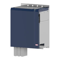
KEB COMBIVERT H6 Instructions For Use Manual (74 pages)
INSTALLATION H6 AXIS MODULES POWER 0.75...110 KW
Brand:
KEB
| Category:
Control Unit
| Size: 8 MB
Table of Contents
Preface
3
Signal Words and Symbols
3
More Symbols
3
Laws and Guidelines
4
Warranty and Liability
4
Support
4
Copyright
4
Table of Contents
5
List of Figures
8
List of Tables
9
Glossary
10
Standards for Drive Converters / Control Cabinets
12
Product Standards that Apply Directly to the Drive Converter
12
Basic Standards to Which Drive Converter Standards Refer Directly
12
Standards that Are Used in the Environment of the Drive Converter
13
1 Basic Safety Instructions
14
Target Group
14
Transport, Storage and Proper Use
14
Installation
15
Electrical Connection
16
EMC-Compatible Installation
17
Voltage Test
17
Insulation Measurement
17
Start-Up and Operation
18
Maintenance
19
Repair
20
Disposal
20
2 Product Description
21
Specified Application
22
Unintended Use
22
Product Features
23
Part Code
24
Table 1: Part Code
24
3 Technical Data
25
Operating Conditions
25
Climatic Ambient Conditions
25
Table 2: Climatic Ambient Conditions
25
Mechanical Ambient Conditions
26
Chemical / Mechanical Active Substances
26
Table 3: Mechanical Ambient Conditions
26
Table 4: Chemical / Mechanical Active Substances
26
Electrical Operating Conditions
27
Device Classification
27
Electromagnetic Compatibility
27
Table 5: Device Classification
27
Table 6: Electromagnetic Compatibility
27
Technical Data of the Axis Modules
28
Figure 1: Overload Characteristic (E.OL, E.OL2)
28
Table 7: Overview of the Device Data Housing B, P
28
Table 8: Overview of the Device Data Housing C, S
29
Table 9: Overview of the Device Data Housing E, G, U, W
30
DC Link Capacities
31
Table 10: DC Link Capacities
31
Mechanical Installation
32
Control Cabinet Installation
32
Figure 2: Control Cabinet Installation
32
Mounting Instructions for Control Cabinet Installation
33
Installation Instructions For Flat Rear Heat Sink
33
Table 11: Mounting Instructions for Control Cabinet Installation
33
Dimensions Central Heat Sink
34
Air Heat Sink
34
Liquid Heat Sinks
34
Figure 3: Main Heat Sink for COMBIVERT H6
34
Dimensions And Weights Of Modules With Flat Rear Heat Sink
35
Figure 4: Dimensions and Weights of the Axis Modules
35
Dimensions of Modules with Air-Cooled Heat Sink
36
Figure 5: Dimensions and Weights Housing P
36
Figure 6: Dimensions and Weights Housing S
37
Figure 7: Dimensions and Weights Housing U
38
Figure 8: Dimensions and Weights Housing W
39
4 Installation and Connection
40
Construction of the Device
40
Figure 9: Front View of the Device
40
Figure 10: Connections of the Front Side
41
Figure 11: View Rear Side of the Device Housing B/P
42
Figure 12: View Rear Side of the Unit
43
Figure 13: View Upper Side of the Unit
44
Figure 14: Status Leds
44
Status LED Axis Module
45
Status LED Safety Module
45
Table 12: Status LED Safety Module
45
Table 13: Status LED Axis Module
45
Connection of the Power Unit
46
Connection of the DC Bus X1D
46
Connection of the 24V Bus X1C
46
Figure 15: Connection of the DC Bus
46
Figure 16: Connection of the 24V Bus
46
Connection of the Motor
47
Motor Terminal X1A
47
Figure 17: Housing B / P Motor Connection
47
Figure 18: Housing C / S Motor Connection
48
Figure 19: Housing E / U Motor Connection
48
Figure 20: Housing G / W Motor Connection
48
Selection of the Motor Cable
49
Interconnection of the Motor
49
Figure 21: Interconnection of the Motor
49
Terminal Block X1B for Motor Temperature and Brake Control
50
Figure 22: Connection of Motor and Voltage Supply
50
Figure 23: Terminal Block X1B
50
Motor Temperature Detection
51
Use of the Temperature Input in KTY Mode
51
Figure 24: Connection of a KTY Sensor
51
Table 14: Motor Temperature Detection
51
Use of the Temperature Input in PTC Mode
52
Brake Control Terminals B+, B
52
Brake Control Terminals BA+, BA- and BB+, BB
52
Figure 25: Brake Control Terminals B+, B
52
Figure 26: Brake Control Terminals BA+, BA- and BB+, BB
52
Table 15: Wiring Example in PTC Mode
52
Encoder Interfaces
53
Figure 27: Encoder Interfaces of Housings B/P
53
Figure 28: Encoder Interfaces of Housings C/S, E/U and G/W
53
Encoder Interface X3AA (Channel 1)
54
Figure 29: Encoder Interface X3AA (Channel 1)
54
Encoder Interface X3AA (Channel 1) for HTL Signals
55
Encoder Interface X3AB (Channel 2)
55
Figure 30: Encoder Interface X3AA (Channel 1) for HTL Signals
55
Description of the Encoder Interfaces
56
Table 16: Description of the Encoder Interfaces
56
Connection of the Control
57
Error Chain Terminal X2C, X2D
57
Error Chain (Channel 1)
57
Error Power Supply Unit (Channel 2)
57
Wiring Example Error Chain
57
Figure 31: Error Chain Terminal X2C, X2D
57
Figure 32: Wiring Example Error Chain
57
Ethercat System Bus Terminal X4B
58
Diagnosis / Visualisation X4A
58
Table 17: Ethercat System Bus Socket X4B
58
Table 18: Diagnosis / Visualisation X4A
58
Digital Inputs and Outputs X2A
59
Technical Data of the Inputs
59
Technical Data of the Outputs
59
Assignment of the Interfaces
59
Figure 33: Assignment of the Interfaces
59
Table 19: Technical Data of the Digital Output
59
Assembly of the Wires to PUSH in Terminals
60
Figure 34: Assembly of the Control Cable
60
Table 20: Wire-End Ferrules and Stripping Length
60
Assignment of the Terminal Block X2A
61
Connection of the Digital Inputs
61
Connection of the Digital Outputs
61
Example for the Control of Digital Inputs and Digital Outputs
61
Figure 35: Assignment of the Terminal Block X2A
61
Figure 36: Connection of the Digital Inputs DI 1
61
Figure 37: Connection of the Digital Outputs DO 1
61
Figure 38: Example for the Control of Digital Inputs and Digital Outputs
61
Safety Module Terminal Block X2B
62
General Instructions for Safety Modules
62
Table 21: Safety Module Terminal Block X2B General Information
62
Module Type 0 Terminal Block X2B
63
Control Release
63
Brake Control
63
Module Type 1 and 2
63
Figure 39: Safety Module Type 0 Terminal Block X2B (Top View)
63
Figure 40: Connection of the Control Release Via Switch and PLC
63
Figure 41: Connection of a Brake Release Via Switch and PLC
63
5 Cooling System
64
Installation of Water-Cooled Units
64
Heat Sink and Operating Pressure
64
Materials in the Cooling Circuit
64
Requirements on the Coolant
65
Table 22: Electrochemical Series / Standard Potentials against Hydrogen
65
Table 23: Requirements on the Coolant
65
Special Requirements for Open and Half-Open Cooling Systems
66
Connection to the Cooling System
66
Coolant Temperature and Moisture Condensation
66
Table 24: Special Requirements for Open and Semi-Open Cooling Systems
66
Emptying the Cooling Circuit
67
Table 25: Dew Point Table
67
Coolant Heating Depending On Power Dissipation And Flow Rate With Water
68
Typically Pressure Drop Depending On The Flow Rate
68
Figure 42: Coolant Heating Depending on Power Dissipation
68
Figure 43: Typically Fall of Pressure Depending on the Rate of Flow
68
6 Certification
69
Ce-Marking
69
UL Marking
69
Further Information and Documentation
70
7 Revision History
71
Advertisement
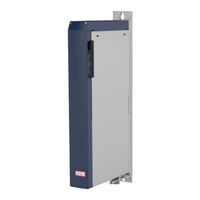
KEB COMBIVERT H6 Instructions For Use Manual (62 pages)
INSTALLATION RECTIFIER MODULE
Brand:
KEB
| Category:
Control Unit
| Size: 5 MB
Table of Contents
Preface
3
Signal Words and Symbols
3
More Symbols
3
Laws and Guidelines
4
Warranty and Liability
4
Support
4
Copyright
4
Table of Contents
5
List of Figures
8
List of Tables
9
Glossary
10
Standards for Drive Converters / Control Cabinets
12
Product Standards that Apply Directly to the Drive Converter
12
Basic Standards to Which Drive Converter Standards Refer Directly
12
Standards that Are Used in the Environment of the Drive Converter
13
1 Basic Safety Instructions
14
Target Group
14
Transport, Storage and Proper Use
14
Installation
15
Electrical Connection
16
EMC-Compatible Installation
17
Voltage Test
17
Insulation Measurement
17
Start-Up and Operation
18
Maintenance
19
Repair
20
Disposal
20
2 Product Description
21
Specified Application
22
Unintended Use
22
Product Features
23
Type Code
24
Table 1: Type Code
24
3 Technical Data
25
Operating Conditions
25
Climatic Ambient Conditions
25
Table 2: Climatic Ambient Conditions
25
Mechanical Ambient Conditions
26
Chemical / Mechanical Active Substances
26
Table 3: Mechanical Ambient Conditions
26
Table 4: Chemical / Mechanical Active Substances
26
Electrical Operating Conditions
27
Device Classification
27
Electromagnetic Compatibility
27
Table 5: Device Classification
27
Table 6: Electromagnetic Compatibility
27
Technical Data of the H6 Power Supply Units
28
Table 7: Technical Data of the H6 Rectifier Modules
28
DC Link Capacity
29
Table 8: DC Link Capacity
29
Mechanical Installation
30
Control Cabinet Installation
30
Figure 1: Control Cabinet Installation
30
Installation Instructions For Flat Rear Heat Sink
31
Dimensions Central Heat Sink
31
Air Heat Sink
31
Liquid Heat Sinks
32
Figure 2: Main Heat Sink for COMBIVERT H6
32
Dimensions And Weights Of The Power Supply Units With Flat Rear Heat Sink
33
Figure 3: Housing C and G
33
Dimensions and Weights of the Power Supply Units with Air Heat Sink
34
Figure 4: Housing S
34
Figure 5: Housing W
35
Mains Chokes
36
Table 9: Mains Chokes
36
Emc Filter
37
Connection Cross Sections and Tightening Torques
37
Table 10: EMC Filter
37
Table 11: Connection Cross Sections and Tightening Torques
37
4 Installation and Connection
38
Construction of the Unit
38
Figure 6: Construction of the Unit
38
Figure 7: Connections of the Front Side
38
Figure 8: View Rear Side of the Unit
39
Figure 9: Internal Wiring of the Rectifier Module (Schematic Diagram)
39
Figure 10: View Upper Side of the Unit
40
Figure 11: Status-Leds
41
Status-LED Safety Module
41
Status-LED Unit
41
Status-Leds
41
Connection of the Power Unit
42
Connection of the DC Bus X1D
42
Connection of the 24V Bus X1C
42
Figure 12: Connection of the DC Bus
42
Figure 13: Connection of the 24V Bus
42
Power Unit Terminal Strips X1A, X1B
43
Table 12: Power Unit Terminal Strips Housing C/S
43
Table 13: Power Unit Terminal Strips Housing G/W
43
Connection for Power Supply
44
Figure 14: Connection for Power Supply
44
Connection Of A Braking Resistor With Fire Protection Monitoring
45
Figure 15: Connection of a Braking Resistor
45
Connection of the Control
46
Error Chain Terminal X2C, X2D
46
Error Linkage Circuit (Channel 1)
46
Error Power Supply Unit (Channel 2)
46
Wiring Example Error Linkage Circuit
46
Figure 16: Error Chain Terminal X2C, X2D
46
Figure 17: Wiring Example Error Linkage Circuit
46
Ethercat System Bus Terminal X4B
47
Diagnosis / Visualisation X4A
47
Table 14: Ethercat System Bus Socket X4B
47
Table 15: Diagnosis / Visualisation X4A
47
Assignment of the Interfaces
48
Digital Inputs and Outputs X2A
48
Technical Data of the Inputs
48
Technical Data of the Outputs
48
Figure 18: Assignment of the Interfaces
48
Table 16: Technical Data of the Outputs
48
Assembly of the Wires to PUSH in Terminals
49
Figure 19: Assembly of the Control Cable
49
Table 17: Wire-End Ferrules and Stripping Length
49
Assignment of the Terminal Block X2A
50
Connection of the Digital Inputs
50
Connection of the Digital Outputs
50
Figure 20: Assignment of the Terminal Block X2A
50
Figure 21: Connection of the Digital Inputs DI 1
50
Figure 22: Connection of the Digital Outputs DO 1
50
Example for the Control of Digital Inputs and Digital Outputs
51
Figure 23: Example for the Control of Digital Inputs and Digital Outputs
51
5 Certification
52
CE Marking
52
UL Marking
52
Further Information and Documentation
54
6 Cooling System
55
Installation of Water-Cooled Units
55
Heat Sink and Operating Pressure
55
Materials in the Cooling Circuit
55
Requirements on the Coolant
56
Table 18: Requirements on the Coolant
56
Connection to the Cooling System
57
Coolant Temperature and Moisture Condensation
57
Table 19: Supply of Temper Coolant
58
Coolant Heating Depending On Power Loss And Flow Rate With Water
59
Typically Fall Of Pressure Depending On The Rate Of Flow
59
Figure 24: Coolant Heating Depending on Power Loss
59
Figure 25: Typically Fall of Pressure Depending on the Rate of Flow
59
7 Revision History
60
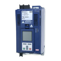
KEB COMBIVERT H6 Instructions For Use Manual (60 pages)
INSTALLATION 24V POWER SUPPLY MODULE
Brand:
KEB
| Category:
Control Unit
| Size: 3 MB
Table of Contents
Preface
3
Signal Words and Symbols
3
More Symbols
3
Laws and Guidelines
4
Warranty and Liability
4
Support
4
Copyright
4
Table of Contents
5
List of Figures
8
List of Tables
9
Glossary
10
Standards for Drive Converters / Control Cabinets
12
Product Standards that Apply Directly to the Drive Converter
12
Basic Standards to Which Drive Converter Standards Refer Directly
12
Standards that Are Used in the Environment of the Drive Converter
13
1 Basic Safety Instructions
14
Target Group
14
Transport, Storage and Proper Use
14
Installation
15
Electrical Connection
16
EMC-Compatible Installation
17
Voltage Test
17
Insulation Measurement
17
Start-Up and Operation
18
Maintenance
19
Repair
20
Disposal
20
2 Product Description
21
Product Features
22
COMBIVERT H6 Series
22
Specified Application
22
Unintended Use
22
Power Supply Module Without Output Terminal
23
Power Supply Module with Output Terminal
23
Control Module with 24V Power Supply
23
Type Code
24
Table 1: Type Code
25
3 Technical Data
26
Operating Conditions
26
Climatic Ambient Conditions
26
Table 2: Climatic Ambient Conditions
26
Mechanical Ambient Conditions
27
Chemical / Mechanical Active Substances
27
Table 3: Mechanical Ambient Conditions
27
Table 4: Chemical / Mechanical Active Substances
27
Electrical Operating Conditions
28
Equipment Classification
28
Electromagnetic Compatibility
28
Table 5: Equipment Classification
28
Table 6: Electromagnetic Compatibility
28
Technical Data of the 24V Modules
29
Table 7: Performance Data
29
Mechanical Installation
30
Control Cabinet Installation
30
Figure 1: Control Cabinet Installation
30
Installation Instructions For Flat Rear Heat Sink
31
Dimensions Central Heat Sink
31
Air Heat Sink
31
Liquid Heat Sinks
32
Figure 2: Main Heat Sink for COMBIVERT H6
32
Dimensions And Weights Of Modules With Flat Rear Heat Sink
33
Figure 3: Dimensions and Weights of Modules with Flat Rear Heat Sink
33
Dimensions and Weights of Modules with Air Heat Sink
34
Figure 4: Dimensions and Weights of Modules with Air Heat Sink
34
4 Installation and Connection
35
Construction of the Unit
35
Figure 5: Front View of the Device
35
Figure 6: Connections of the Front Side
36
Figure 7: View Rear Side of the Unit
37
Figure 8: View of the Unit Top Side for Control Type „D
38
Figure 10: Status Leds
39
Figure 9: View of the Unit Top Side for Control Type „C
39
Status Leds
39
Connection of the Power Unit
40
Connection of the DC Bus X1D
40
Connection of the 24V Bus X1C
40
Figure 11: Connection of the DC Bus
40
Figure 12: Connection of the 24V Bus
40
Connection of the External 24V Supply X1B
41
Internal Wiring with Option (Schematic Diagram))
41
Figure 13: Connection of the External 24V Supply X1B
41
Figure 14: Internal Wiring with Option (Schematic Diagram))
41
Connection Of The 24V Supply Hardware Configuration 1 (With DC Bus) Rectifier Module
42
Figure 15: Connection of the 24V Supply (with DC Bus) Rectifier Module
42
Connection Of The 24V Supply Hardware Configuration 3 (With DC Bus) With Aic
43
Figure 16: Connection of the 24V Supply (with DC Bus) with AIC
43
Connection Of The 24V Supply Hardware Configuration 2 (Without DC Bus) With Aic
44
Figure 17: Connection of the 24V Supply (Without DC Bus) with AIC
44
Connection of the Control Type „D
45
Inputs and Outputs X2A
45
Assignment of the Terminal Block X2A
45
Technical Data of the Digital Inputs Control Type „D
45
Technical Data of the Digital Outputs Control Type „D
45
Technical Data of the 24V Outputs
45
Figure 18: Assignment of the Terminal Block X2A
45
Table 8: Technical Data of the Digital Inputs Control Type „D
45
Table 9: Technical Data of the Digital Outputs Control Type „D
45
Assembly of the Wires to PUSH in Terminals
46
Figure 19: Assembly of the Control Cable
46
Table 10: Wire-End Ferrules and Stripping Length
46
Ethercat System Bus Terminals X4B
47
Fieldbus Slave Module Socket X4C
47
Diagnosis / Visualisation X4A
47
Table 11: Ethercat System Bus Socket X4B
47
Table 12: Fieldbus Slave Module Socket X4C
47
Table 13: Diagnosis / Visualisation X4A
47
Assignment of the Interfaces
48
Figure 20: Assignment of the Interfaces
48
Connection of the Control Type „B
49
Connection of the Control Type „C
49
Assignment of the Terminal Block X2A
49
Technical Data of the Inputs
49
Technical Data of the Outputs
49
Technical Data of the 24V Outputs
49
Figure 21: Assignment of the Terminal Block X2A
49
Table 14: Technical Data of the Outputs
49
5 Certification
50
Ce Marking
50
UL Marking
51
Further Information and Documentation
52
6 Cooling System
53
Installation of Water-Cooled Units
53
Heat Sink and Operating Pressure
53
Materials in the Cooling Circuit
53
Requirements on the Coolant
54
Table 15: Electrochemical Voltage Series / Standard Potentials against Hydrogen
54
Table 16: Requirements on the Coolant
54
Connection to the Cooling System
55
Coolant Temperature and Moisture Condensation
55
Table 17: Supply of Temper Coolant
56
Coolant Heating Depending On Power Loss And Flow Rate With Water
57
Typically Fall Of Pressure Depending On The Rate Of Flow
57
Figure 22: Coolant Heating Depending on Power Loss
57
Figure 23: Typically Fall of Pressure Depending on the Rate of Flow
57
7 Revision History
58
Advertisement
KEB COMBIVERT H6 Instructions For Use Manual (40 pages)
Functional safety
Brand:
KEB
| Category:
Controller
| Size: 1 MB
Table of Contents
Preface
3
Signal Words and Symbols
3
More Symbols
3
Laws and Guidelines
4
Warranty and Liability
4
Support
4
Copyright
4
Table of Contents
5
List of Figures
7
List of Tables
8
Glossary
9
Standards for Drive Converters / Control Cabinets
11
Product Standards that Apply Directly to the Drive Converter
11
Basic Standards to Which Drive Converter Standards Refer Directly
11
Standards that Are Used in the Environment of the Drive Converter
12
1 Basic Safety Instructions
13
Target Group
13
Validity of this Manual
13
Electrical Connection
14
Start-Up and Operation
14
2 Product Description
15
Device Identification
15
Table 1: Numerical Code
15
3 Safety Functions
16
General Instructions
16
Safe Torque off (Safe Torque off - STO)
17
Emergency Stop According en 60204
18
Calculation of the Rotation Angle Triggered by the Jerk
18
Table 2: Calculation of the Jerk
18
Classification Of Sto According Iec 61508
19
Classification Of Sto According En Iso 13849
19
Safe Brake Control (Safe Brake Control - SBC)
19
Requirements for the Brake
19
Table 3: Classifications of STO
19
Table 4: Requirements for the Brake
19
Classification Of Sbc According Iec 61508
20
Classification Of Sbc According En Iso 13849
20
Table 5: Classifications of SBC
20
4 Description of the Terminals
21
Figure 1: Description of the Terminals
21
Table 6: Mechanical Specification of Terminal Strip X2B
21
Inputs
22
Specification Of The Sto Inputs
22
STO with OSSD Signals
22
Specification Of The Sbc Inputs
22
SBC with OSSD Signals
22
Table 7: Specification of the STO Inputs
22
Table 8: STO with OSSD Signals
22
Table 9: Specification of the SBC Inputs
22
Outputs
23
Output STO
23
Output SBC
23
Brake Output
23
Status Leds
23
Status-LED Safety Module
23
Table 10: Status-LED Safety Module
23
5 Installation
24
Additional Instructions
24
6 Functional Descriptions
25
Status of the Safety Module
25
Table 11: Status of the Safety Module
25
Function Description STO
26
Functional Description SBC
26
Single Axis Module
27
Double Axis Module
27
Table 12: Braking Handling Single Axis Module
27
Table 13: Braking Handling Double Axis Module
27
Setting of Status Bits by the SBC Function
28
Table 14: Setting of Status Bits by the SBC Function
28
Table 15: Setting of Status Bits by the SBC Function
28
Monitoring of the SBC Function
29
7 Wiring Examples
30
Direct Switching off with Emergency Stop Switch
30
Figure 2: Direct Switching off with Emergency Stop Switch
30
Direct Switching off with Emergency Stop Switch and Monitoring of the Wiring
31
Figure 3: Direct Switching off with Emergency Stop Switch and Monitoring of the Wiring
31
Direct Switching off by Safety Module with Test Pulses
32
Figure 4: Direct Switching off by Safety Module with Test Pulses
32
Wiring SS1
33
Figure 5: Wiring SS1
33
8 Change of the Safety Module
34
Certification
35
Annex to the Declaration of Conformity
35
Table 16: Annex to the Declaration of Conformity
35
10 Revision History
37
Notes
38
Advertisement
Related Products
KEB COMBIVERT F5
KEB COMBIVERT F5 Servo
KEB combiverty
KEB COMBIVERT G6
KEB COMBIVERT 10F6 Series
KEB COMBIVERT 12F6 Series
KEB COMBIVERT 13F6 Series
KEB COMBIVERT 14F6 Series
KEB COMBIVERT 15F6 Series
KEB COMBIVERT 16F6 Series
KEB Categories
DC Drives
Controller
Inverter
Control Unit
Industrial Equipment
More KEB Manuals
Login
Sign In
OR
Sign in with Facebook
Sign in with Google
Upload manual
Upload from disk
Upload from URL