KEB COMBIVERT H6 Instructions For Use Manual
Installation 24v power supply module
Hide thumbs
Also See for COMBIVERT H6:
- Instructions for use manual (40 pages) ,
- Instructions for use manual (74 pages) ,
- Instructions for use manual (62 pages)

Subscribe to Our Youtube Channel
Related Manuals for KEB COMBIVERT H6


Summary of Contents for KEB COMBIVERT H6
- Page 1 COMBIVERT H6 INSTRUCTIONS FOR USE | INSTALLATION 24V POWER SUPPLY MODULE Translation of original manual Document 20105427 EN 04...
-
Page 3: Preface
PREfAcE Preface The described hard- and software are developments of the KEB Automation KG. The enclosed documents correspond to conditions valid at printing. Misprint, mistakes and technical changes reserved. Signal words and symbols Certain operations can cause hazards during the installation, operation or thereafter. -
Page 4: Laws And Guidelines
If applicable, the license terms of this software are contained in the instructions for use. The instructions for use are already available to you, can be downloaded free of charge from the KEB website or can be requested from the respec- tive KEB contact person. -
Page 5: Table Of Contents
1.7 Disposal ............................20 2 Product Description ............ 21 2.3 Product features ..........................22 2.3.1 COMBIVERT H6 series ...................... 22 2.1 Specified application ........................22 2.2 Unintended use ..........................22 2.3.2 24V power supply module without output terminal ............. 23 2.3.3 24V power supply module with output terminal .............. - Page 6 TAbLE Of cONTENTS 3.1.2 Mechanical ambient conditions ..................27 3.1.3 Chemical / mechanical active substances ................27 3.1.4 Electrical operating conditions .................... 28 3.1.4.1 Equipment classification ....................28 3.1.4.2 Electromagnetic compatibility ..................28 3.2 Technical data of the 24V modules ....................29 3.3 Mechanical installation .........................
- Page 7 TAbLE Of cONTENTS 5 Certification ..............50 5.1 cE Marking ............................. 50 5.2 UL Marking ............................. 51 5.3 further information and documentation ..................52 6 cooling System............53 6.1 Installation of water-cooled units ....................53 6.1.1 Heat sink and operating pressure ..................53 6.1.2 Materials in the cooling circuit ....................
-
Page 8: List Of Figures
LIST Of fIGURES List of figures Figure 1: Control cabinet installation ....................30 Figure 2: Main heat sink for COMBIVERT H6 ................. 32 Figure 3: Dimensions and weights of modules with flat rear heat sink ........... 33 Figure 4: Dimensions and weights of modules with air heat sink............ 34 Figure 5: Front view of the device .................... -
Page 9: List Of Tables
LIST Of TAbLES List of Tables Table 1: Type code ........................25 Table 2: Climatic ambient conditions ..................... 26 Table 3: Mechanical ambient conditions ..................27 Table 4: Chemical / mechanical active substances ............... 27 Table 5: Equipment classification ....................28 Table 6: Electromagnetic compatibility .................. -
Page 10: Glossary
Open source real-time interface for IP xx Degree of protection (xx for level) sensors and actuators (DIN 5008) KEB product The KEB product is subject of this Fieldbus system manual. Complete drive module including Silicium temperature sensor (pola- auxiliary equipment (control cabinet) - Page 11 GLOSSARY Term used in the safety technology (EN 61508-1...7) for the size of error probability per hour Programmable logic controller PT100 Temperature sensor with R0=100Ω PT1000 Temperature sensor with R0=1000Ω PTC-resistor for temperature detec- tion Pulse width modulation RJ45 Modular connector with 8 lines Synchronous sensorless closed loop SELV Safety Extra Low Voltage (<...
-
Page 12: Standards For Drive Converters / Control Cabinets
STANDARDS fOR DRIVE cONVERTERS / cONTROL cAbINETS Standards for drive converters / control cabinets Product standards that apply directly to the drive converter EN 61800-2 Adjustable speed electrical power drive systems - Part 2: General requirements - Rating specifications for low voltage adjustable frequency a.c. power drive systems (VDE 0160-102, IEC 61800-2) EN 61800-3 Speed-adjustable electrical drives. Part 3: EMC requirements and specific test methods (VDE 0160-103, IEC 61800-3) -
Page 13: Standards That Are Used In The Environment Of The Drive Converter
STANDARDS fOR DRIVE cONVERTERS / cONTROL cAbINETS EN 61000-4-5 Electromagnetic compatibility (EMC) - Part 4-5: Testing and measurement techniques - Surge immunity test (IEC 61000-4-5); German version EN 61000-4-5 EN 61000-4-6 Electromagnetic compatibility (EMC) - Part 4-6: Testing and measurement techniques - Immunity to conducted disturbances, induced by radio-frequency fields (IEC 61000-4-6); German version EN 61000-4-6 EN 61000-4-34... -
Page 14: Basic Safety Instructions
► Read the instructions for use ! ► Observe the safety and warning instructions ! ► If anything is unclear, please contact KEB Automation KG ! 1.1 Target group This instruction manual is determined exclusively for electrical personnel. Electrical per- sonnel for the purpose of this instruction manual must have the following qualifications: •... -
Page 15: Installation
bASIc SAfETY INSTRUcTIONS Drive converters contain electrostatic sensitive components. ► Avoid contact. ► Wear ESD-protective clothing. Do not store drive converters • in the environment of aggressive and/or conductive liquids or gases. • with direct sunlight. • outside the specified environmental conditions. 1.3 Installation DANGER Do not operate in an explosive environment! -
Page 16: Electrical Connection
If personnel protection is required during installation of the system, suitable protective devices must be used for drive converters. www.keb.de/fileadmin/media/Manuals/knowledge/04_techinfo/00_gene- ral/ti_rcd_0400_0002_gbr.pdf Installations which include drive converter shall be equipped with additional control and protective devices in accordance with the relevant applicable safety requirements, e.g. -
Page 17: Emc-Compatible Installation
According to EN 60204-1 it is permissible to disconnect already tested com- ponents. Drive converters of the KEB Automation KG are delivered ex works voltage tested to 100% according to product standard. 1.4.3 Insulation measurement An insulation measurement (in accordance with EN 60204-1 chapter 18.3) with DC... -
Page 18: Start-Up And Operation
If a drive converter with electrolytic capacitors in a DC link (see technical data) has not been in operation for more than one year, observe the following instructions. www.keb.de/fileadmin/media/Manuals/knowledge/04_techinfo/00_gene- ral/ti_format_capacitors_0400_0001_gbr.pdf NOTICE continuous operation (S1) with load > 60 % ! Premature ageing of the electrolytic capacitors ! ►... -
Page 19: Maintenance
For applications that require cyclic switching off and on of the drive converter, maintain an off-time of at least 5 min after the last switch on. If you require shorter cycle times please contact KEB Automation KG. Short-circuit resistance The drive converters are conditional short-circuit proof. After resetting the internal pro- tection devices, the function as directed is guaranteed. -
Page 20: Repair
1.7 Disposal Electronic devices of the KEB Automation KG are exclusively professional devices for further industrial processing (so-called B2B devices). Manufacturers of B2B devices are obliged to take back and recycle devices manufac- tured after 14.08.2018. -
Page 21: Product Description
PRODUcT DEScRIPTION 2 Product Description The product family COMBIVERT H6 is optimized for the use in multi-axis drives. The structure is modular and thus it can be optimally adapted to the respective requirements. A system consists of the following components:... -
Page 22: Product Features
SPEcIfIED APPLIcATION 2.1 Specified application The COMBIVERT H6 is a DC-coupled drive system for the control of different axes. It serves exclusively for the control and regulation of three-phase motors. It is intended for the installation into electrical systems or machines. -
Page 23: Power Supply Module Without Output Terminal
PRODUcT fEATURES Control • EtherCAT system bus for transmission of setpoints and actual values between control, Active Front End modules and axis modules. • Drive profiles according to CiA402 Regulation • Synchronous and asynchronous machines, with and without encoder feedback Error bus • Channel 1: Error output of the connected DC buses •... -
Page 24: Type Code
A: No encoder interface Encoder interface B: Two-channel multi encoder interface 1: BASIC 2: PRO ADVANCED Software configuration 3-9: KEB default A-Z: Customer / special version 1: No DC bus connection 2: DC bus connection / operation at rectifier modules (B6) 3: DC bus connection / operation at Active Front End... -
Page 25: Table 1: Type Code
TYPE cODE x x H 6 x x x - x x x x 01: No fieldbus slave module 02: reserved 03: PROFIBUS ® 1) 04: Interbus Fieldbus slave module 05: CANopen ® 2) 06: ProfiNet 07: POWERLINK 08: EtherCAT ® 3) Table 1: Type code The type code is not used as order code, it is only used for identification ! PROFIBUS®... -
Page 26: Technical Data
OPERATING cONDITIONS 3 Technical Data 3.1 Operating conditions 3.1.1 climatic ambient conditions Storage Standard class Notes Surrounding temperature EN 60721-3-1 -25…55 °C Relative humidity 5…95 % (without condensation) EN 60721-3-1 Storage height – – Max. 3000 m above sea level Transport Standard class Notes... -
Page 27: Mechanical Ambient Conditions
OPERATING cONDITIONS 3.1.2 Mechanical ambient conditions Storage Standard class Notes Vibration amplitude 0.3 mm (2…9 Hz) Vibration limits EN 60721-3-1 Acceleration amplitude 1 m/s² (9…200 Hz) Shock limit values EN 60721-3-1 40 m/s²; 22 ms Transport Standard class Notes Vibration amplitude 3.5 mm (2…9 Hz) Vibration limits EN 60721-3-2 Acceleration amplitude 10 m/s²... -
Page 28: Electrical Operating Conditions
OPERATING cONDITIONS 3.1.4 Electrical operating conditions 3.1.4.1 Equipment classification Requirement Standard class Notes – EN 61800-5-1 Overvoltage category EN 60664-1 – Non-conductive pollution, occasional conden- Pollution degree EN 60664-1 sation when PDS is out of service Table 5: Equipment classification 3.1.4.2 Electromagnetic compatibility The indicated values are only valid for units with external filter. -
Page 29: Technical Data Of The 24V Modules
TEcHNIcAL DATA Of THE 24V MODULES 3.2 Technical data of the 24V modules Housing b, P Input data mains supply Rated input voltage Rated input voltage UL N_UL Input voltage range 320…528 Input voltage range 210…750 in_dc Mains frequency / Hz 50/60 ±2 Phases Rated input power... -
Page 30: Mechanical Installation
MEcHANIcAL INSTALLATION 3.3 Mechanical installation 3.3.1 control cabinet installation Mounting distances Dimension Distance in mm Distance in inch 1) Minimum distance for cooling 2) Distance to preceding elements in the cabinet door. ATTENTION Horizontal installation in the control cabinet must be done with special care and the displacement between the units must be kept to a minimum. -
Page 31: Installation Instructions For Flat Rear Heat Sink
► The machine builder is responsible for the cooling of the units. Heat-conducting paste Information about the correct application of the heat-conducting paste are available at www.keb.de under the search term "Heat-conducting paste“. Select correct flow temperature for liquid coolers ► The flow temperature must be choose in such a way, that no mois- ture condensation occurs. -
Page 32: Liquid Heat Sinks
Following liquid heat sinks are available, if no usable cooling surface exists at customer side: Heat sink cabinet outcut Size L1 in mm L2 in mm L3 in mm 04H6TFW-0400 06H6TFW-0600 08H6TFW-0800 10H6TFW-1000 1052 1035 1006 12H6TFW-1200 1252 1235 1206 Figure 2: Main heat sink for COMBIVERT H6... -
Page 33: Dimensions And Weights Of Modules With Flat Rear Heat Sink
MEcHANIcAL INSTALLATION 3.3.4 Dimensions and weights of modules with flat rear heat sink Housing size Module width in mm Weight in kg B (with control module) Figure 3: Dimensions and weights of modules with flat rear heat sink... -
Page 34: Dimensions And Weights Of Modules With Air Heat Sink
MEcHANIcAL INSTALLATION 3.3.5 Dimensions and weights of modules with air heat sink 49,7 Housing size Module width in mm Weight in kg Figure 4: Dimensions and weights of modules with air heat sink... -
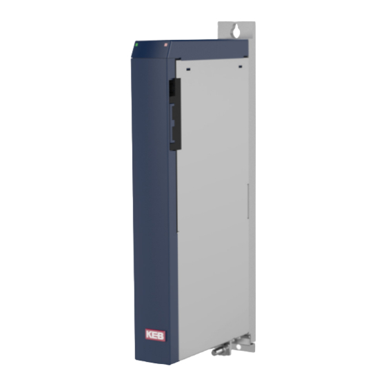
Page 35: Installation And Connection
cONSTRUcTION Of THE UNIT 4 Installation and connection 4.1 construction of the unit front view front without cover Remove the front cover • Press with your thumb centrally the bottom of the lid. • Slightly lift the lid at the bottom. •... -
Page 36: Figure 6: Connections Of The Front Side
cONSTRUcTION Of THE UNIT Description Terminal connections of the front side Terminal Description +24V bus X1C.1 X1C.3 +24V bus X1C.2 X1C.4 DC bus+ X1D.1 X1D.3 DC bus+ DC bus- X1D.2 X1D.4 DC bus- Microfuse (optional) 5 x 20 mm, T 20 A Cable fastening (strain (optional) —... -
Page 37: Figure 7: View Rear Side Of The Unit
cONSTRUcTION Of THE UNIT View rear side of the unit Size b/P Line terminal strip X1A Mains input 3-phase 400 V cross-section Tightening torque 0.2...6 mm² 0.7 Nm AWG 24-10 6.2 lb inch Protective earth and function earth 2 x screw terminal for ring cable lug Ø... -
Page 38: Figure 8: View Of The Unit Top Side For Control Type „D
cONSTRUcTION Of THE UNIT View of the unit top side for control type „D“ Digital inputs and outputs Dig. input 4 15 DC 24 V/< 0.7 A output Dig. input 3 13 DC 24 V/< 0.7 A output Dig. input 2 DC 24 V/<... -
Page 39: Status Leds
cONSTRUcTION Of THE UNIT View of the unit top side for control type „c“ Digital inputs and outputs Output 3 (DC 24 V / 7 A) Output 2 (DC 24 V / 5 A) DI1 digital input DO1 digital output voltage (release for output DC output 5 A) -
Page 40: Connection Of The Power Unit
The 24V bus supplies the control and the driver circuit of the axis module and the power supply and regenerative unit with 24V DC voltage. This voltage is usually provided by the COMBIVERT H6 power supply module, but can also be used by an existing 24 V voltage source. -
Page 41: Connection Of The External 24V Supply X1B
cONNEcTION Of THE POWER UNIT NOTICE Parallel connection of 24V power supply modules is not permitted. 4.2.3 connection of the external 24V supply X1b Name function connection Tightening torque Ring cable lug: Connection for external 24V forked < 8 mm 1.3 Nm supply 12 lb inch... -
Page 42: Connection Of The 24V Supply Hardware Configuration 1 (With Dc Bus) Rectifier Module
cONNEcTION Of THE POWER UNIT 4.2.4 Connection of the 24V supply hardware configuration 1 (with DC bus) rectifier module ⑦ 24/0Vdc 24/0Vdc DC-Bus DC-Bus DC-Bus ⑥ ⑧ ⑨ Error Error L12 L22 L32 +PA - PB L3 L2 L1 U V W ④... -
Page 43: Connection Of The 24V Supply Hardware Configuration 3 (With Dc Bus) With Aic
cONNEcTION Of THE POWER UNIT 4.2.5 Connection of the 24V supply hardware configuration 3 (with DC bus) with AIC ⑫ ⑩ ϑ ⑥ ⑦ Error Error 24/0Vdc 24/0Vdc DC-Bus DC-Bus ⑧ ⑨ U V W U V W 24Vdc 0Vdc U V W ⑤... -
Page 44: Connection Of The 24V Supply Hardware Configuration 2 (Without Dc Bus) With Aic
cONNEcTION Of THE POWER UNIT 4.2.6 Connection of the 24V supply hardware configuration 2 (without DC bus) with AIC ⑫ ⑩ ϑ ⑥ ⑦ Error Error 24/0Vdc 24/0Vdc DC-Bus DC-Bus ⑧ ⑨ U V W U V W 24Vdc 0Vdc U V W ⑤... -
Page 45: Connection Of The Control Type „D
cONNEcTION Of THE cONTROL TYPE „D“ 4.3 connection of the control type „D“ 4.3.1 Inputs and outputs X2A 4.3.1.1 Assignment of the terminal block X2A Digital inputs and outputs function Term. Term. function Digital input 4 DC 24 V/< 0.7 A output Digital input 3 DC 24 V/<... -
Page 46: Assembly Of The Wires To Push In Terminals
cONNEcTION Of THE cONTROL TYPE „D“ 4.3.2 Assembly of the wires to PUSH IN terminals ATTENTION Malfunctions caused by loose cable connections! ► Observe metal sleeve length and stripping length Metal sleeve Stripping cross-section Wire-end ferrule length length 0.50 mm 10 mm 12 mm with plastic collars... -
Page 47: Ethercat System Bus Terminals X4B
cONNEcTION Of THE cONTROL TYPE „D“ 4.3.3 Ethercat system bus terminals X4b The EtherCAT system bus serves for the communication of the master with the axis modules and the power supply and regenerative unit. „CanOpen over EtherCAT “ is used as protocol. Description of the LEDs RJ45 socket Assignment... -
Page 48: Assignment Of The Interfaces
cONNEcTION Of THE cONTROL TYPE „D“ cOMbIVIS 6 A current XML file is required for the operation with COMBIVIS 6. At active inter- net connection the download can directly be done from COMBIVIS 6. 4.3.5.1 Assignment of the interfaces reserved - do not assign ! reserved - do not assign ! TxD (RS232) DGND (reference potential) RxD (RS232) TxD-A (RS485) RxD-A (RS485) -
Page 49: Connection Of The Control Type „B
cONNEcTION Of THE cONTROL TYPE „b“ 4.4 connection of the control type „b“ Devices with control type "B" consist only of the 24V power supply module. They have no control module and no 24 V output terminal.Further connection is therefore not necessary. -
Page 50: Certification
cERTIfIcATION 5 Certification 5.1 cE Marking CE marked power supplies were developed and manufactured to comply with the regu- lations of the Low-Voltage Directive 2014/35/EU and EMC directive (2014/30/EU). The start-up (i.e. the starting of normal operation) of the 24V power supplies is prohib- ited until it is determined that the unit or machinery complies with the machine directive (2006/42/EC). -
Page 51: Ul Marking
5.2 UL Marking Acceptance according to UL is marked at KEB inverters with the adjacent logo on the type plate. To be conform according to UL for use on the North American and Canadian Market the following additionally instructions must be observed (summary of original texts of the UL-Files): •... -
Page 52: Further Information And Documentation
5.3 further information and documentation You find supplementary manuals and instructions for the download under www.keb.de/service/downloads General instructions • EMC and safety instructions • Manuals for further control boards Instruction and information for construction and development • Input fuses in accordance with UL • Programming manual for control and power unit •... -
Page 53: Cooling System
DC link circuit capacitors and power modules (IGBT). Also the temper- ature dependent switching losses are positively effected. The use of water-cooled KEB COMBIVERT drive converters is offered in the drive technology, because there are pro- cess-caused coolants available with some applications. -
Page 54: Requirements On The Coolant
INSTALLATION Of WATER-cOOLED UNITS Standard Standard Material Generated Ion Material Generated Ion potential potential Aluminium -1.67 V Copper 0.34 V Manganese -1.05 V Carbon 0.74 V Zinc -0.76 V Silver 0.80 V Chrome -0.71 V Platinum 1.20 V Iron -0.44 V Gold 1.42 V Cadmium... -
Page 55: Connection To The Cooling System
Pay attention to flux direction and check tightness ! • The cooling flow must always be started before starting the KEB COMBIVERT. The connection to the cooling system can occur as closed or open cooling circuit. The connection to a closed cycle cooling circuit is recommended, because the danger of contamination of coolant is very small. -
Page 56: Table 17: Supply Of Temper Coolant
INSTALLATION Of WATER-cOOLED UNITS In order to avoid a moisture condensation the following possibilities can be done. The application of both methods is recommended. Supply of temper coolant This is possible by using heatings in the cooling circuit for the control of the coolant tem- perature. -
Page 57: Coolant Heating Depending On Power Loss And Flow Rate With Water
INSTALLATION Of WATER-cOOLED UNITS 6.1.6 Coolant heating depending on power loss and flow rate with water ΔT / K 5 l/min 10 l/min 20 l/min 30 l/min 40 l/min 50 l/min 100 l/min / kW Figure 22: Coolant heating depending on power loss 6.1.7 Typically fall of pressure depending on the rate of flow l/min Figure 23:... -
Page 58: Revision History
REVISION HISTORY 7 Revision History Version Date Description 2015-07 Conversion to document version 2016-08 Heatsink concepts 2017-09 New CI, general revision, linkage with InCopy components 2018-11 Revision of the product description and design of the device 2019-06 Updates made... - Page 59 Room 1709, 415 Missy 2000 725 Su Seo Dong E-Mail: vb.belgien@keb.de Internet: www.keb.de Gangnam Gu 135- 757 Seoul Republic of Korea Tel: +82 2 6253 6771 Fax: +82 2 6253 6770 E-Mail: vb.korea@keb.de KEB South America - Regional Manager brazil Rua Dr.
- Page 60 Automation with Drive www.keb.de KEB Automation KG Suedstrasse 38 32683 Barntrup Tel. +49 5263 401-0 E-Mail: info@keb.de...
Need help?
Do you have a question about the COMBIVERT H6 and is the answer not in the manual?
Questions and answers