Sign In
Upload
Manuals
Brands
Juniper Manuals
Switch
EX4200-24P
Juniper EX4200-24P Manuals
Manuals and User Guides for Juniper EX4200-24P. We have
3
Juniper EX4200-24P manuals available for free PDF download: Hardware Manual, Complete Hardware Manual, Specifications
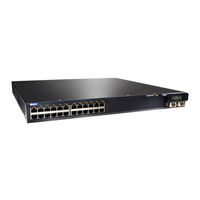
Juniper EX4200-24P Hardware Manual (314 pages)
EX4200 Series
Brand:
Juniper
| Category:
Switch
| Size: 4.67 MB
Table of Contents
Table of Contents
3
About the Documentation
17
Documentation and Release Notes
17
Supported Platforms
17
Documentation Conventions
17
Table 1: Notice Icons
18
Table 2: Text and Syntax Conventions
18
Documentation Feedback
19
About the Documentation
19
Requesting Technical Support
20
Self-Help Online Tools and Resources
20
Opening a Case with JTAC
20
Chassis Components and Descriptions
23
System Overview
23
Overview
23
Chapter 1 System Overview
25
EX4200 Switches Hardware Overview
25
EX4200 Switches
25
Switches
25
Uplink Modules
26
Power over Ethernet Ports
26
EX4200 Switch Models
27
Table 3: EX4200 Switch Models
27
EX4200 Switch Hardware and CLI Terminology Mapping
28
Table 4: CLI Equivalents of Terms Used in Documentation for EX4200
29
Chapter 2 Chassis Components and Descriptions
31
Chassis Physical Specifications for EX4200 Switches
31
Table 5: Physical Specifications of the Switch Chassis
31
Field-Replaceable Units in EX4200 Switches
32
Front Panel of an EX4200 Switch
33
Figure 1: EX4200 Switch with 48 Gigabit Ethernet Ports
33
Figure 2: EX4200 Switch with 24 Gigabit Ethernet Ports
33
Chassis Components and Descriptions
33
Rear Panel of an EX4200 Switch
34
Figure 3: EX4200-24F Switch with 24 SFP Ports
34
LCD Panel in EX4200 Switches
35
Figure 4: EX4200 Switch Rear Panel
35
Figure 5: LCD Panel
35
LCD Panel Modes
36
LCD Panel Menus
37
Table 6: LCD Panel Menu Options
37
Uplink Modules in EX4200 Switches
40
SFP Uplink Module
41
SFP+ Uplink Module and SFP+ Macsec Uplink Module
41
Figure 6: SFP Uplink Module
41
Figure 7: SFP+ and SFP+ Macsec Uplink Module
42
XFP Uplink Module
43
Chassis Status Leds in EX4200 Switches
43
Figure 8: XFP Uplink Module
43
Figure 9: Chassis Status Leds in an EX4200 Switch
44
Table 7: Chassis Status Leds in an EX4200 Switch
44
Management Port Leds in EX4200 Switches
45
Network Port Leds in EX4200 Switches
46
Figure 10: Leds on the Management Port on an EX4200 Switch
46
Table 8: Link/Activity LED on the Management Port on EX4200 Switches
46
Table 9: Status LED on the Management Port on EX4200 Switches
46
Figure 11: Leds on the Network Ports on the Front Panel
47
Figure 12: Leds on the Uplink Module Ports on the SFP Uplink Module
47
Figure 13: Leds on the Uplink Module Ports on the SFP+ and SFP+ Macsec Uplink
48
Figure 14: Leds on the Uplink Module Ports on the XFP Uplink Module
48
Modules
48
Table 10: Link/Activity LED on Network Ports
48
Table 11: Status LED on Network Ports
50
Chapter 3 Cooling System and Airflow
53
Cooling System and Airflow in an EX4200 Switch
53
Fan Tray
53
Airflow Direction in the EX4200 Switch Chassis
53
Figure 15: Fan Tray Used in an EX4200 Switch
53
Figure 16: Airflow through the EX4200 Switch Chassis
54
Chapter 4 Power Supplies
55
Power Supply in EX4200 Switches
55
AC Power Supplies
56
Figure 17: 320 W AC Power Supply
56
DC Power Supplies
57
Figure 18: 600 W and 930 W AC Power Supplies
57
Power Supplies
57
Poe Power Budget and AC Power Supplies
58
Figure 19: DC Power Supply
58
Table 12: Power Supply Rating and Poe Power Budget for EX4200 Switch
58
AC Power Supply Leds in EX4200 Switches
59
Table 13: AC Power Supply Leds
59
DC Power Supply Leds in EX4200 Switches
60
Table 14: DC Power Supply Leds
60
Chapter 5 Viewing System Information
61
Dashboard for EX Series Switches
61
Graphical Chassis Viewer
62
Table 15: Details of a Virtual Chassis Member Switch
62
System Information Panel
63
Viewing System Information
63
Table 16: Status of a Member Switch in a Virtual Chassis
63
Table 17: System Information
63
Health Status Panel
65
Table 18: Health Status
65
Capacity Utilization Panel
67
Alarms Panel
67
Table 19: Capacity Utilization
67
File System Usage
68
Chassis Viewer
68
Table 20: Chassis Viewer for EX2200 Switches
68
Table 21: Chassis Viewer for EX2200-C Switches
69
Table 22: Chassis Viewer for EX3200, EX3300, and EX4200 Switches
69
Table 23: Chassis Viewer for EX4300 Switches
71
Table 24: Chassis Viewer for EX4500 Switches
72
Table 25: Chassis Viewer for EX4550 Switches
73
Table 26: Chassis Viewer for EX4600 Switches
75
Table 27: Chassis Viewer for EX6210 Switches
75
Table 28: Chassis Viewer for EX8208 Switches
76
Table 29: Chassis Viewer for EX8216 Switches
78
Table 30: Chassis Viewer for XRE200 External Routing Engines
78
Site Planning, Preparation, and Specifications
81
Preparation Overview
81
Transceiver and Cable Specifications
81
Chapter 6 Preparation Overview
83
Preparation Overview
83
Site Preparation Checklist for EX4200 Switches
83
Table 31: Site Preparation Checklist
83
Environmental Requirements and Specifications for EX Series Switches
84
Table 32: EX Series Switch Environmental Tolerances
85
General Site Guidelines
88
Site Electrical Wiring Guidelines
89
Table 33: Site Electrical Wiring Guidelines
89
Cabinet Requirements
90
Rack Requirements
90
Table 34: Rack Requirements and Specifications
90
Requirements for Mounting an EX4200 Switch on a Desktop or Wall
91
Table 35: Cabinet Requirements and Specifications
91
Figure 20: Clearance Requirements for Airflow and Hardware Maintenance for
92
Figure 21: Airflow through the EX4200 Switch Chassis
93
Switches
95
Chapter 7 Power Specifications and Requirements
95
AC Power Cord Specifications for EX4200 Switches
96
Figure 22: AC Plug Types
97
Table 38: AC Power Cord Specifications
97
Calculating the EX Series Switch Fiber-Optic Cable Power Budget
98
Calculating the EX Series Switch Fiber-Optic Cable Power Margin
98
Power Specifications and Requirements
99
Table 39: Estimated Values for Factors Causing Link Loss
99
Power Specifications and Requirements
95
Power Specifications for EX4200 Switches
95
Table 36: AC Power Supply Electrical Specifications
95
Table 37: DC Power Supply Electrical Specifications
95
Chapter 8 Transceiver and Cable Specifications
101
Pluggable Transceivers Supported on EX4200 Switches
101
Pluggable Transceivers Supported on EX Series Switches
102
SFP+ Direct Attach Copper Cables for EX Series Switches
103
Cable Specifications
103
Figure 23: SFP+ Direct Attach Copper Cables for EX Series Switches
103
Table 40: Software Support for SFP+ Passive Direct Attach Copper Cables for EX Series Switches
103
Table 41: SFP+ Direct Attach Copper Cable Specifications
106
Standards Supported by These Cables
109
Management Cable Specifications
109
Understanding EX Series Switches Fiber-Optic Cable Signal Loss, Attenuation
110
And Dispersion
110
Signal Loss in Multimode and Single-Mode Fiber-Optic Cable
110
Table 42: Specifications of Cables to Connect to Management Devices
110
Attenuation and Dispersion in Fiber-Optic Cable
111
Chapter 9 Pinout Specifications
113
USB Port Specifications for an EX Series Switch
114
RJ-45 Management Port Connector Pinout Information
115
Table 44: RJ-45 Management Port Connector Pinout Information
115
Port, QSFP+ Port, SFP+ Port, and SFP Port Connector Pinout Information
116
Table 45: 10/100/1000BASE-T Ethernet Network Port Connector Pinout
116
Table 46: SFP Network Port Connector Pinout Information
116
Table 47: SFP+ Network Port Connector Pinout Information
117
Table 48: QSFP+ Network Port Connector Pinout Information
118
RJ-45 to DB-9 Serial Port Adapter Pinout Information
120
Table 49: RJ-45 to DB-9 Serial Port Adapter Pinout Information
120
Uplink Modules Connector Pinout Information for EX4200 Switches
121
Table 50: Uplink Modules Connector Pinout Information
121
Virtual Chassis Ports Connector Pinout Information for EX4200 Switches
129
Table 51: Virtual Chassis Ports (Vcps) Connector Pinout Information
129
Pinout Specifications
113
Console Port Connector Pinout Information
113
Table 43: Console Port Connector Pinout Information
113
Chapter 10 Planning the Virtual Chassis
133
Configurations
133
Ports Used to Interconnect Virtual Chassis Members
133
Number of Switches, Required Software Releases, and Member Roles that You Configure in the Virtual Chassis
134
Table 52: Number of Switches and Switch Roles for an EX4200 Virtual Chassis
134
Virtual Chassis Module
135
Table 53: Number of Switches and Switch Roles for an EX4500 Virtual Chassis
135
Table 54: Number of Switches and Switch Roles for an EX4550 Virtual Chassis
135
Table 55: Number of Switches and Switch Roles for a Mixed EX4200, EX4500, and EX4550 Virtual Chassis, Per Junos os Release
135
Switch Role and Member ID on the LCD Panel
136
Planning EX4200, EX4500, and EX4550 Virtual Chassis
136
Table 56: Virtual Chassis Components to Consider When Planning an EX4200
136
Table 57: Cabling Requirements for a Virtual Chassis
137
Virtual Chassis Cabling Configuration Examples for EX4200 Switches
138
Figure 24: EX4200 Switches Mounted on a Single Rack and Connected in a Ring
139
Figure 25: EX4200 Switches Mounted on a Single Rack and Connected in a Ring
139
Topology Using Short and Long Cables: Option 1
139
Figure 26: EX4200 Switches Mounted on a Single Rack and Connected in a Ring Topology Using Short and Medium Cables
140
Figure 27: EX4200 Switches Mounted on Adjacent Racks and Connected in a
140
Figure 28: EX4200 Switches Mounted on Adjacent Racks and Connected in a
140
Initial Installation and Configuration
141
Chapter 11 Unpacking the Switch
143
Unpacking an EX4200 Switch
143
Parts Inventory (Packing List) for an EX4200 Switch
144
Figure 29: Unpacking an EX4200 Switch
144
Table 58: Packing List for an EX4200 Switch
145
Registering Products-Mandatory for Validating Slas
146
Chapter 12 Installing the Switch
149
Installing and Connecting an EX4200 Switch
149
Mounting an EX4200 Switch
150
Mounting an EX4200 Switch on a Desk or Other Level Surface
151
Mounting an EX4200 Switch on Two Posts in a Rack or Cabinet
152
Figure 30: Attaching Rubber Feet to an EX4200 Switch Chassis
152
Figure 31: Attaching the Mounting Bracket to the Side Panel of the Switch
154
Figure 32: Mounting the Switch on Two Posts in a Rack
154
Mounting an EX4200 Switch on Four Posts in a Rack or Cabinet
155
Figure 33: Attaching the Front-Mounting Bracket to the Side Mounting-Rail
157
Figure 34: Attaching the Side Mounting-Rail to the Switch Chassis
157
Figure 35: Mounting the Switch to the Front Posts in a Rack
158
Figure 36: Sliding the Rear Mounting-Blades into the Side-Mounting Rail
158
Mounting an EX4200 Switch in a Recessed Position in a Rack or Cabinet
159
Mounting an EX4200 Switch on a Wall
160
Figure 37: Attaching Wall-Mount Brackets to the Switch Chassis
161
Installing and Removing EX4200 Switch Hardware Components
162
Figure 38: Mounting the Switch on a Wall
162
Chapter 13 Connecting the Switch to Power
165
Connecting Earth Ground to an EX Series Switch
165
Parts and Tools Required for Connecting an EX Series Switch to Earth Ground
165
Table 59: Parts and Tools Required for Connecting an EX Series Switch to Earth Ground
166
Special Instructions to Follow before Connecting Earth Ground to a
166
Special Instructions to Follow before Connecting Earth Ground to a
167
Switch
168
Table 60: Special Instructions to Follow before Connecting Earth Ground to a
168
Figure 39: Connecting the Grounding Lug to a Switch Mounted on Four Posts of
169
Connecting Earth Ground to an EX Series Switch
170
Figure 40: Connecting a Grounding Cable to an EX Series Switch
170
Connecting AC Power to an EX4200 Switch
171
Figure 41: Connecting the AC Power Cord Retainer Clip to an AC Power Supply in an EX4200 Switch
173
Figure 42: Connecting an AC Power Cord to an AC Power Supply in an EX4200 Switch
173
Connecting DC Power to an EX4200 Switch
174
Figure 43: DC Power Supply in an EX4200 Switch
174
Figure 44: Removing the Terminal Block Cover from a DC Power Supply
175
Figure 45: Securing Ring Lugs to the Terminals on the DC Power Supply
177
Chapter 14 Connecting the Switch to the Network
179
Connecting a Device to a Network for Out-Of-Band Management
179
Connecting a Device to a Management Console by Using an
179
Figure 46: RJ-45 Connector on an Ethernet Cable
179
Connector
180
Figure 47: Connecting a Device to a Network for Out-Of-Band Management
180
Figure 48: RJ-45 Connector on an Ethernet Cable
180
Connecting a Fiber-Optic Cable
181
Figure 49: Connecting a Device to a Management Console through a Console
181
Figure 50: Connecting a Device Directly to a Management Console
181
A Device
182
Figure 51: Connecting a Fiber-Optic Cable to an Optical Transceiver Installed in
182
Chapter 15 Performing Initial Configuration
183
EX4200 Default Configuration
183
Connecting and Configuring an EX Series Switch (CLI Procedure)
187
Connecting and Configuring an EX Series Switch (J-Web Procedure)
190
Figure 52: LCD Panel in an EX3200, EX4200, EX4500, EX4550, or EX8200
192
Figure 53: LCD Panel in an EX4300 Switch
192
Configuring the LCD Panel on EX Series Switches (CLI Procedure)
195
Disabling or Enabling Menus and Menu Options on the LCD Panel
195
Configuring a Custom Display Message
196
Installing, Maintaining, and Replacing Components
199
Chapter 16 Replacing Cooling System Component
201
Installing a Fan Tray in an EX4200 Switch
201
Removing a Fan Tray from an EX4200 Switch
202
Figure 54: Installing a Fan Tray in an EX4200 Switch
202
Figure 55: Removing a Fan Tray from an EX4200 Switch
202
Chapter 17 Replacing Power Supply
205
Installing a Power Supply in an EX4200 Switch
205
Figure 56: Installing a Power Supply in an EX4200 Switch
206
Removing a Power Supply from an EX4200 Switch
207
Figure 57: Removing a Power Supply from the Switch
208
Chapter 18 Replacing Uplink Module
209
Installing an Uplink Module in an EX4200 Switch
209
Removing an Uplink Module from an EX4200 Switch
211
Figure 58: Installing an Uplink Module in an EX4200 Switch
211
Figure 59: Sliding the Screwdriver to the Narrow Part of the Keyhole
213
Figure 60: Removing an Uplink Module from an EX4200 Switch
213
Chapter 19 Replacing Transceiver
215
Installing a Transceiver
215
Removing a Transceiver
217
Figure 61: Installing a Transceiver
217
Figure 62: Removing an SFP, SFP+, XFP, or a QSFP+ Transceiver
219
Chapter 20 Maintaining and Replacing Fiber-Optic Cable
221
Connecting a Fiber-Optic Cable
221
Disconnecting a Fiber-Optic Cable from a Device
222
Figure 63: Connecting a Fiber-Optic Cable to an Optical Transceiver Installed in
222
Maintaining Fiber-Optic Cables
223
Chapter 21 Replacing a Member Switch to Virtual Chassis
225
Adding a New EX4200 Switch to an Existing EX4200 Virtual Chassis
225
Procedure)
225
Adding a New Switch to an Existing Virtual Chassis Within the same Wiring Closet
225
Adding a New Switch to an Existing Preprovisioned Virtual Chassis Using
225
Chassis
227
Autoprovisioning
229
Replacing a Member Switch of a Virtual Chassis Configuration
231
Procedure)
231
Remove, Repair, and Reinstall the same Switch
231
Remove a Member Switch, Replace It with a Different Switch, and Reapply the Old Configuration
232
Remove a Member Switch and Make Its Member ID Available for Reassignment to a Different Switch
234
Chapter 22 Maintaining and Replacing Virtual Chassis Cable
235
Connecting a Virtual Chassis Cable to an EX4200 Switch
235
Disconnecting a Virtual Chassis Cable from an EX4200 Switch
236
Figure 64: Connecting a Virtual Chassis Cable to an EX4200 Switch
236
Figure 65: Virtual Chassis Cable Connector in an EX4200 Switch
237
Chapter 23 Contactingcustomer Supportandreturningthe Chassisor
239
Components
239
Returning an EX4200 Switch or Component for Repair or Replacement
239
Locating the Serial Number on an EX4200 Switch or Component
240
Listing the Switch and Components Details with the CLI
240
Locating the Chassis Serial Number ID Label on an EX4200 Switch
240
Locating the Serial Number ID Labels on Frus in an EX4200 Switch
241
Contacting Customer Support to Obtain Return Material Authorization
241
Figure 66: Location of the Serial Number ID Label on an EX4200 Switch
241
Packing an EX4200 Switch or Component for Shipping
242
Packing an EX4200 Switch for Shipping
242
Packing EX4200 Switch Components for Shipping
243
Troubleshooting
245
Chapter 24 Alarms and Syslog Messages
247
Understanding Alarm Types and Severity Levels on EX Series Switches
247
Table 61: Alarm Terms
247
Chassis Component Alarm Conditions on EX4200 Switches
248
Table 62: Chassis Component Alarm Conditions on EX4200 Switches
249
Checking Active Alarms with the J-Web Interface
253
Monitoring System Log Messages
254
Table 63: Summary of Key Alarm Output Fields
254
Table 64: Filtering System Log Messages
255
Table 65: Viewing System Log Messages
257
Chapter 25 Troubleshooting Switch Components
259
Troubleshooting Network Interfaces on EX4200 Switches
259
The Interface on the Port in Which an SFP or SFP+ Transceiver Is Installed Is down
259
Troubleshooting Virtual Chassis Port Connectivity on an EX4200 Switch
260
Virtual Chassis Port (VCP) Connection Does Not Work
260
Troubleshooting Power Supply Installation Alarms on EX4200 Switches
260
The Switch Displays the "Unsupported PSU" Alarm
261
Safety and Compliance Information
263
Chapter 26 General Safety Guidelines and Warnings
265
Definitions of Safety Warning Levels
266
Qualified Personnel Warning
268
Warning Statement for Norway and Sweden
269
Chapter 27 Fire Safety Requirements
271
Chapter 28 Installation Safety Guidelines and Warnings
273
Installation Instructions Warning
273
Chassis Lifting Guidelines
274
Restricted Access Warning
274
Ramp Warning
276
Rack-Mounting and Cabinet-Mounting Warnings
276
Wall-Mounting Warning for EX4200 Switches
280
Grounded Equipment Warning
280
Chapter 29 Radiation and Laser Safety Guidelines and Warnings
283
Laser and LED Safety Guidelines and Warnings
283
General Laser Safety Guidelines
283
Class 1 Laser Product Warning
284
Class 1 LED Product Warning
284
Laser Beam Warning
284
Radiation from Open Port Apertures Warning
285
Chapter 30 Maintenance and Operational Safety Warnings
287
Maintenance and Operational Safety Guidelines and Warnings
287
Battery Handling Warning
287
Jewelry Removal Warning
288
Lightning Activity Warning
289
Operating Temperature Warning
290
Product Disposal Warning
291
Chapter 31 Electrical Safety Guidelines and Warnings
293
General Electrical Safety Guidelines and Warnings
293
Action to Take after an Electrical Accident
294
Prevention of Electrostatic Discharge Damage
295
AC Power Electrical Safety Guidelines
296
Figure 67: Placing a Component into an Antistatic Bag
296
AC Power Disconnection Warning
297
DC Power Electrical Safety Guidelines for Switches
298
DC Power Disconnection Warning
301
DC Power Grounding Requirements and Warning
302
DC Power Wiring Sequence Warning
303
DC Power Wiring Terminations Warning
305
Multiple Power Supplies Disconnection Warning
306
TN Power Warning
306
Chapter 32 Agency Approvals and Compliance Statements
309
Agency Approvals for EX Series Switches
309
Compliance Statements for EMC Requirements for EX Series Switches
310
Canada
310
European Community
311
Israel
311
Japan
311
Korea
312
United States
312
FCC Part 15 Statement
312
Nonregulatory Environmental Standards
313
Compliance Statements for Acoustic Noise for EX Series Switches
314
Advertisement
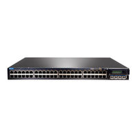
Juniper EX4200-24P Complete Hardware Manual (280 pages)
Brand:
Juniper
| Category:
Switch
| Size: 4.56 MB
Table of Contents
Table of Contents
7
About this Topic Collection
19
How to Use this Guide
19
List of EX Series Guides for Junos os Release 10.3
19
Component Descriptions
19
Downloading Software
21
Documentation Symbols Key
22
Documentation Feedback
23
Requesting Technical Support
24
Self-Help Online Tools and Resources
24
Opening a Case with JTAC
24
Switch and Components Overview and Specifications
25
EX3200 and EX4200 Switches Overview
25
EX3200 and EX4200 Switches Overview
27
EX3200 and EX4200 Switches Hardware Overview
27
EX3200 and EX4200 Switch Types
27
EX3200 Switches
28
EX4200 Switches
28
Uplink Modules
29
Power over Ethernet (Poe) Ports
29
EX3200 and EX4200 Switches Overview
29
EX3200 Switch Models
30
EX4200 Switch Models
30
Table 1: EX3200 Switch Models
30
Table 2: EX4200 Switch Models
30
Chassis Physical Specifications for EX3200 and EX4200 Switches
31
Front Panel of an EX3200 Switch
31
Table 3: Physical Specifications of the EX3200 and EX4200 Switch Chassis
31
Rear Panel of an EX3200 Switch
32
Figure 1: EX3200 Switch with 48 Gigabit Ethernet Ports
32
Figure 2: EX3200 Switch with 24 Gigabit Ethernet Ports
32
Front Panel of an EX4200 Switch
33
Figure 3: EX3200 Switch Rear Panel
33
Figure 4: EX4200 Switch with 48 Gigabit Ethernet Ports
34
Figure 5: EX4200 Switch with 24 Gigabit Ethernet Ports
34
Figure 6: EX4200-24F Switch with 24 SFP Ports
34
Figure 8: LCD Panel in EX3200 and EX4200 Switches
34
Rear Panel of an EX4200 Switch
35
Figure 7: EX4200 Switch Rear Panel
35
Component Descriptions
37
LCD Panel in EX3200 and EX4200 Switches
37
LCD Panel Modes
38
LCD Panel Menus
39
Component Descriptions
39
Table 4: LCD Panel Menu Options in EX3200 and EX4200 Switches
39
Field-Replaceable Units in EX3200 and EX4200 Switches
42
Chassis Status Leds in EX3200 Switches
43
Figure 9: Chassis Status Leds in an EX3200 Switch
43
Table 5: Chassis Status Leds in an EX3200 Switch
43
Chassis Status Leds in EX4200 Switches
44
Figure 10: Chassis Status Leds in an EX4200 Switch
44
Table 6: Chassis Status Leds in an EX4200 Switch
44
Network Port Leds in EX3200 and EX4200 Switches
45
Figure 11: Leds on the Network Ports on the Front Panel
45
Figure 12: Leds on the Uplink Module Ports on the SFP Uplink Module
45
Figure 13: Leds on the Uplink Module Ports on the SFP+ Uplink Module
46
Figure 14: Leds on the Uplink Module Ports on the XFP Uplink Module
46
Table 7: Link/Activity LED on Network Ports in EX3200 and EX4200
46
Table 8: Status LED on Network Ports in EX3200 and EX4200 Switches
48
Management Port Leds in EX3200 and EX4200 Switches
49
Figure 15: Leds on the Management Port on an EX3200 Switch
50
Figure 16: Leds on the Management Port on an EX4200 Switch
50
Table 9: Link/Activity LED on the Management Port on EX3200 and EX4200
50
Table 10: Status LED on the Management Port on EX3200 and EX4200
50
Power Supply in EX3200 and EX4200 Switches
51
Figure 17: 320 W AC Power Supply in EX3200 and EX4200 Switches
52
Figure 18: 600 W and 930 W AC Power Supplies in EX3200 and EX4200
52
Figure 19: DC Power Supply in EX3200 and EX4200 Switches
52
Table 11: Minimum Power Requirements for an EX3200 Switch
52
Table 12: Minimum Power Requirements for an EX4200 Switch
53
AC Power Supply Leds in EX3200 and EX4200 Switches
54
DC Power Supply Leds in EX3200 and EX4200 Switches
54
Table 13: AC Power Supply Leds in EX3200 and EX4200 Switches
54
Cooling System and Airflow in an EX3200 Switch
55
Table 14: DC Power Supply Leds in EX3200 and EX4200 Switches
55
Figure 20: Fan Tray Used in an EX3200 Switch
56
Figure 21: Airflow through the EX3200 Switch Chassis
56
Cooling System and Airflow in an EX4200 Switch
57
Figure 22: Fan Tray Used in an EX4200 Switch
57
Figure 23: Airflow through the EX4200 Switch Chassis
57
Uplink Modules in EX3200 and EX4200 Switches
58
SFP Uplink Module
59
Figure 24: SFP Uplink Module
59
Figure 25: SFP+ Uplink Module
60
XFP Uplink Module
61
Figure 26: XFP Uplink Module
61
Component Specifications
63
USB Port Specifications for an EX Series Switch
63
Network Port Connector Pinout Information for an EX3200 or EX4200
63
Switch
63
Table 15: Network Port Connector Pinout Information for an EX3200 or EX4200
64
Console Port Connector Pinout Information for an EX Series Switch
65
Switch
65
Component Specifications
65
Table 16: EX Series Switches Console Port Connector Pinout Information
65
Table 17: Management Port Connector Pinout Information for EX3200 and EX4200 Switches
66
Optical Interface Support in EX3200 and EX4200 Switches
67
Table 18: Optical Interface Support and Copper Interface Support for Gigabit Ethernet SFP Transceivers in EX3200 and EX4200 Switches
68
Table 19: Optical Interface Support for Fast Ethernet SFP Transceivers in EX3200 and EX4200 Switches
79
Table 20: Optical Interface Support for Gigabit Ethernet SFP+ Transceivers in
85
Table 21: Optical Interface Support for Gigabit Ethernet XFP Transceivers in
90
SFP+ Direct Attach Cables for EX Series Switches
93
Cable Specifications
94
Table 22: SFP+ Direct Attach Cable Specifications
95
Standards Supported by These Cables
97
Table 23: Uplink Modules Connector Pinout Information for EX3200 and EX4200
97
Switches
98
Virtual Chassis Ports Connector Pinout Information for EX4200 Switches
105
Table 24: Virtual Chassis Ports (Vcps) Connector Pinout Information
105
Planning for Switch Installation
109
Site Preparation
111
Site Preparation Checklist for EX3200 and EX4200 Switches
111
Table 25: Site Preparation Checklist
111
General Site Guidelines for EX Series Switches
113
Site Electrical Wiring Guidelines for EX Series Switches
113
Environmental Requirements and Specifications for EX Series Switches
114
Table 26: Site Electrical Wiring Guidelines
114
Table 27: EX Series Switch Environmental Tolerances
115
Mounting and Clearance Requirements
117
Rack Requirements for EX3200 and EX4200 Switches
117
Table 28: Rack Requirements and Specifications for the Switch
117
Cabinet Requirements for EX3200 and EX4200 Switches
118
Wall
119
Table 29: Cabinet Requirements and Specifications for the Switch
119
Clearance Requirements for Airflow and Hardware Maintenance for EX3200 and EX4200 Switches
120
Figure 27: Clearance Requirements for Airflow and Hardware Maintenance for
120
Figure 28: Airflow through the EX3200 Switch Chassis
121
Figure 29: Airflow through the EX4200 Switch Chassis
122
Cable Specifications
123
Network Cable Specifications for EX3200 and EX4200 Switches
123
Planning Power Requirements
125
Power Specifications for EX3200 and EX4200 Switches
125
Table 30: AC Power Supply Electrical Specifications for EX3200 and EX4200
125
Table 31: DC Power Supply Electrical Specifications for EX3200 and EX4200
125
AC Power Cord Specifications for EX3200 and EX4200 Switches
126
Table 32: AC Power Cord Specifications
126
Figure 30: AC Plug Types
127
Switch
129
Planning the Virtual Chassis
130
Virtual Chassis Cabling Configuration Examples for EX4200 Switches
131
Figure 31: EX4200 Switches Mounted on a Single Rack and Connected in a Ring
131
Figure 32: EX4200 Switches Mounted on a Single Rack and Connected in a Ring
132
Figure 33: EX4200 Switches Mounted on a Single Rack and Connected in a Ring Topology Using Short and Medium Cables
132
Figure 34: EX4200 Switches Mounted on Adjacent Racks and Connected in a
132
Procedure)
133
Adding a New Switch to an Existing Virtual Chassis Configuration Within the same Wiring Closet
133
Figure 35: EX4200 Switches Mounted on Adjacent Racks and Connected in a
133
Adding a New Switch from a Different Wiring Closet to an Existing Virtual Chassis Configuration
134
Adding a New Switch to an Existing Preprovisioned Virtual Chassis Configuration Using Autoprovisioning
136
Installing and Connecting the Switch and Switch Components
139
Installing the Switch
141
Installing and Connecting an EX3200 or EX4200 Switch
141
Unpacking an EX3200 or EX4200 Switch
142
Figure 36: Unpacking an EX3200 or EX4200 Switch
143
Table 33: Inventory of Components Provided with an EX3200 or EX4200
143
Mounting an EX3200 or EX4200 Switch
144
Mounting an EX3200 or EX4200 Switch on a Desk or Other Level Surface
145
Figure 37: Attaching Rubber Feet to an EX3200 or EX4200 Switch Chassis
145
Mounting an EX3200 or EX4200 Switch on Two Posts in a Rack or Cabinet
146
Figure 38: Attaching the Mounting Bracket Along the Front of the Switch
147
Mounting an EX3200 or EX4200 Switch on Four Posts in a Rack or Cabinet
148
Figure 39: Mounting the Switch on Two Posts in a Rack
148
Figure 40: Attaching the Front Bracket to the Side-Rail Bracket
150
Figure 41: Attaching the Side-Rail Bracket to the Switch Chassis
150
Figure 42: Mounting the Switch to the Front Posts in a Rack
151
Figure 43: Sliding the Rear Brackets to the Rear of a Four-Post Rack
151
Mounting an EX3200 or EX4200 Switch in a Recessed Position in a Rack or Cabinet
152
Mounting an EX3200 or EX4200 Switch on a Wall
152
Figure 44: Attaching Wall-Mount Brackets to an EX3200 or EX4200 Switch
153
Figure 45: Mounting an EX3200 or EX4200 Switch on a Wall
154
Installing Switch Components
155
Installing and Removing EX3200 and EX4200 Switch Hardware
155
Components
155
Installing a Power Supply in an EX3200 or EX4200 Switch
156
Installing a Fan Tray in an EX3200 or EX4200 Switch
157
Figure 46: Installing a Power Supply in an EX3200 or EX4200 Switch
157
Figure 47: Installing a Fan Tray in an EX3200 Switch
158
Figure 48: Installing a Fan Tray in an EX4200 Switch
158
Installing an Uplink Module in an EX3200 or EX4200 Switch
159
Figure 49: Installing an Uplink Module in an EX3200 or EX4200 Switch
160
Installing a Transceiver in an EX Series Switch
161
Figure 50: Installing a Transceiver in an EX Series Switch
162
Connecting a Virtual Chassis Cable to an EX4200 Switch
163
Figure 51: Connecting a Virtual Chassis Cable to an EX4200 Switch
164
Connecting the Switch
165
Connecting Earth Ground to an EX Series Switch
165
Figure 52: Connecting a Grounding Cable to an EX Series Switch
165
Connecting Earth Ground to an EX2200 or EX3200 Switch
166
Connecting Earth Ground to an EX4200 Switch
167
Connecting Earth Ground to an EX4500 Switch
168
Figure 53: Connecting the Grounding Lug to an EX4200 Switch on a Four-Post
168
Connecting Earth Ground to an EX8208 Switch
169
Connecting Earth Ground to an EX8216 Switch
170
Connecting AC Power to an EX3200 or EX4200 Switch
171
Figure 54: Connecting the AC Power Cord Retainer Clip to an AC Power Supply in an EX3200 or EX4200 Switch
172
Figure 55: Connecting an AC Power Cord to an AC Power Supply in an EX3200 or EX4200 Switch
172
Connecting DC Power to an EX3200 or EX4200 Switch
173
Figure 56: DC Power Supply in an EX3200 or EX4200 Switch
173
Figure 57: Removing the Terminal Block Cover from a DC Power Supply in an EX3200 or EX4200 Switch
174
Figure 58: Securing Ring Lugs to the Terminals on the DC Power Supply in an EX3200 or EX4200 Switch
175
Connecting an EX Series Switch to a Network for Out-Of-Band Management
176
Figure 59: Ethernet Cable Connector
176
Connecting an EX Series Switch to a Management Console
177
Figure 60: Connecting an EX Series Switch to a Network for Out-Of-Band
177
Figure 61: Ethernet Cable Connector
177
Figure 62: Connecting an EX Series Switch to a Management Console through
178
Figure 63: Connecting an EX Series Switch Directly to a Management
178
Connecting an EX Series Switch to a Modem
179
Setting the Serial Console Speed for the Switch
179
Configuring the Modem
180
Table 34: Port Settings
180
Connecting the Modem to the Console Port
181
Figure 64: Ethernet Cable Connector
181
Connecting a Fiber-Optic Cable to an EX Series Switch
182
Figure 65: Connecting a Fiber-Optic Cable to an Optical Transceiver Installed in
183
Performing Initial Configuration
185
EX3200 and EX4200 Default Configuration
185
Connecting and Configuring an EX Series Switch (CLI Procedure)
189
Connecting and Configuring an EX Series Switch (J-Web Procedure)
191
Figure 66: LCD Panel in an EX3200, EX4200, EX4500, or EX8200 Switch
192
Removing Switch Components
195
Removing Switch Components
197
Components
197
Removing a Power Supply from an EX3200 or EX4200 Switch
198
Figure 67: Removing a Power Supply from an EX3200 or EX4200 Switch
199
Removing a Fan Tray from an EX3200 or EX4200 Switch
200
Figure 68: Removing a Fan Tray from an EX3200 Switch
200
Removing an Uplink Module from an EX3200 or EX4200 Switch
201
Figure 69: Removing a Fan Tray from an EX4200 Switch
201
Removing a Transceiver from an EX Series Switch
203
Figure 70: Sliding the Screwdriver to the Narrow Part of the Keyhole
203
Figure 71: Removing an Uplink Module from an EX3200 or EX4200 Switch
203
Disconnecting a Fiber-Optic Cable from an EX Series Switch
205
Figure 72: Removing a Transceiver from an EX Series Switch
205
Disconnecting a Virtual Chassis Cable from an EX4200 Switch
206
Replacing a Member Switch of a Virtual Chassis Configuration
207
Procedure)
207
Figure 73: Virtual Chassis Cable Connector in an EX4200 Switch
207
Remove, Repair, and Reinstall the same Switch
208
Remove a Member Switch, Replace with a Different Switch, and Reapply the Old Configuration
208
Remove a Member Switch and Make Its Member ID Available for Reassignment to a Different Switch
209
Switch and Component Maintenance
211
Routine Maintenance
213
Maintaining Fiber-Optic Cables in EX Series Switches
213
Troubleshooting Switch Components
215
Troubleshooting Switch Components
217
Troubleshooting Network Interfaces on EX3200 and EX4200 Switches
217
The Interface on One of the Last Four Built-In Network Ports in an EX3200 Switch (for Example, Interface Ge-0/0/23) Is down
217
The Interface on the Port in Which an SFP or SFP+ Transceiver Is Installed in an SFP+ Uplink Module Is down
218
Troubleshooting Uplink Module Installation or Replacement on EX3200 and EX4200 Switches
218
Virtual Chassis Port (VCP) Connection Does Not Work
218
One of the Last Four Network Ports on an EX3200 Switch with an SFP or SFP+ Uplink Module Installed Is Disabled
219
Returning Hardware
221
Returning the Switch or Switch Components
223
Replacement
223
Locating the Serial Number on an EX3200 or EX4200 Switch or Component
224
Listing the Switch and Components Details with the CLI
224
Switch
224
Figure 74: Location of the Serial Number ID Label on an EX3200 Switch
224
Locating the Serial Number ID Labels on Frus in an EX3200 or EX4200 Switch
225
Contacting Customer Support to Obtain Return Materials Authorization for EX
225
Series Switches
225
Figure 75: Location of the Serial Number ID Label on an EX4200 Switch
225
Packing an EX3200 or EX4200 Switch or Component for Shipping
226
Packing an EX3200 or EX4200 Switch for Shipping
227
Packing EX3200 or EX4200 Switch Components for Shipping
228
Safety Information
229
General Safety Information
231
General Safety Guidelines and Warnings for EX Series Switches
231
Definitions of Safety Warning Levels for EX Series Switches
232
Fire Safety Requirements for EX Series Switches
234
Qualified Personnel Warning for EX Series Switches
235
Warning Statement for Norway and Sweden for EX Series Switches
236
Radiation and Laser Warnings
237
Laser and LED Safety Guidelines and Warnings for EX Series Switches
237
General Laser Safety Guidelines
237
Class 1 Laser Product Warning
237
Class 1 LED Product Warning
238
Laser Beam Warning
238
Radiation from Open Port Apertures Warning for EX Series Switches
240
Installation and Maintenance Safety Information
243
Installation Instructions Warning for EX Series Switches
243
Chassis Lifting Guidelines for EX3200 and EX4200 Switches
244
Ramp Warning for EX Series Switches
244
Rack-Mounting and Cabinet-Mounting Warnings for EX Series Switches
245
Wall-Mounting Warning for EX3200 and EX4200 Switches
249
Grounded Equipment Warning for EX Series Switches
250
Switches
250
Battery Handling Warning
251
Jewelry Removal Warning
252
Lightning Activity Warning
253
Operating Temperature Warning
254
Product Disposal Warning
256
Power and Electrical Safety Information
259
General Electrical Safety Guidelines and Warnings for EX Series Switches
259
Prevention of Electrostatic Discharge Damage on EX Series Switches
260
Figure 76: Place a Component into an Antistatic Bag
261
AC Power Electrical Safety Guidelines for EX Series Switches
262
AC Power Disconnection Warning for EX Series Switches
263
Multiple Power Supplies Disconnection Warning for EX Series Switches
264
Switches
264
DC Power Electrical Safety Guidelines for EX Series Switches
264
DC Power Disconnection Warning for EX Series Switches
266
DC Power Grounding Requirements and Warning for EX Series Switches
267
DC Power Wiring Sequence Warning for EX Series Switches
268
DC Power Wiring Terminations Warning for EX Series Switches
270
TN Power Warning for EX Series Switches
271
In Case of Electrical Accident: Action to Take on an EX Series Switch
272
Compliance Information
273
Compliance Information
275
Agency Approvals for EX Series Switches
275
Compliance Statements for EMC Requirements for EX Series Switches
276
Canada
276
European Community
277
Japan
277
United States
277
FCC Part 15 Statement
277
Non-Regulatory Environmental Standards
278
Compliance Statements for Acoustic Noise for EX Series Switches
278
Declaration of Conformity for EX3200 and EX4200 Switches
279
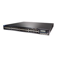
Juniper EX4200-24P Specifications (13 pages)
EX4200 ETHERNET SWITCHES WITH VIRTUAL CHASSIS TECHNOLOGY
Brand:
Juniper
| Category:
Switch
| Size: 0.78 MB
Table of Contents
Product Description
1
Features and Benefits
3
Policy Manager
4
Limited Lifetime Warranty
5
Product Options
5
Physical Specifications
6
Link Aggregation
9
Troubleshooting
10
Ordering Information
11
About Juniper Networks
12
Advertisement
Advertisement
Related Products
Juniper EX 4200 24F
Juniper EX 4200 24P
Juniper EX 4200 24T
Juniper EX4200-24T
Juniper EX4200-24T-DC
Juniper EX4200-24PX
Juniper EX4200-24F
Juniper EX4200-24F-S
Juniper EX4200-24F-DC
Juniper EX 4200
Juniper Categories
Network Router
Switch
Gateway
Software
Network Hardware
More Juniper Manuals
Login
Sign In
OR
Sign in with Facebook
Sign in with Google
Upload manual
Upload from disk
Upload from URL