Juniper EX3200 Series Complete Hardware Manual
Hide thumbs
Also See for EX3200 Series:
- Hardware manual (310 pages) ,
- Quick start manual (10 pages) ,
- Datasheet (8 pages)

Related Manuals for Juniper EX3200 Series


Summary of Contents for Juniper EX3200 Series
- Page 1 Complete Hardware Guide for EX3200 and EX4200 Ethernet Switches Published: 2010-08-11 Revision 11 Copyright © 2010, Juniper Networks, Inc.
- Page 2 Products made or sold by Juniper Networks or components thereof might be covered by one or more of the following patents that are owned by or licensed to Juniper Networks: U.S. Patent Nos. 5,473,599, 5,905,725, 5,909,440, 6,192,051, 6,333,650, 6,359,479, 6,406,312, 6,429,706, 6,459,579, 6,493,347, 6,538,518, 6,538,899, 6,552,918, 6,567,902, 6,578,186, and 6,590,785.
- Page 3 The terms and conditions for using this software are described in the software license contained in the acknowledgment to your purchase order or, to the extent applicable, to any reseller agreement or end-user purchase agreement executed between you and Juniper Networks.
- Page 4 Juniper, even if such feature, function, service, application, operation, or capability is enabled without a key; (g) distribute any key for the Software provided by Juniper to any third party; (h) use the...
- Page 5 Customer did not originally purchase from Juniper or an authorized Juniper reseller; (k) disclose the results of testing or benchmarking of the Software to any third party without the prior written consent of Juniper; or (l) use the Software in any manner other than as expressly provided herein.
- Page 6 (or services are accessed by) the Software shall be a third party beneficiary with respect to this Agreement, and such licensor or vendor shall have the right to enforce this Agreement in its own name as if it were Juniper. In addition, certain third party software may be provided with the Software and is subject to the accompanying license(s), if any, of its respective owner(s).
-
Page 7: Table Of Contents
Cooling System and Airflow in an EX3200 Switch ......31 Copyright © 2010, Juniper Networks, Inc. - Page 8 Power Specifications for EX3200 and EX4200 Switches ....101 AC Power Cord Specifications for EX3200 and EX4200 Switches ... 102 viii Copyright © 2010, Juniper Networks, Inc.
- Page 9 Configuring the Modem ......... . 156 Copyright © 2010, Juniper Networks, Inc.
- Page 10 One of the last four network ports on an EX3200 switch with an SFP or SFP+ uplink module installed is disabled ......195 Copyright © 2010, Juniper Networks, Inc.
- Page 11 Product Disposal Warning ........232 Copyright © 2010, Juniper Networks, Inc.
- Page 12 Compliance Statements for Acoustic Noise for EX Series Switches ..254 Declaration of Conformity for EX3200 and EX4200 Switches ....255 Copyright © 2010, Juniper Networks, Inc.
- Page 13 Planning Power Requirements ........101 Copyright © 2010, Juniper Networks, Inc.
- Page 14 EX3200 or EX4200 Switch ........151 Copyright © 2010, Juniper Networks, Inc.
- Page 15 Power and Electrical Safety Information ......235 Figure 76: Place a Component into an Antistatic Bag ..... . 237 Copyright © 2010, Juniper Networks, Inc.
- Page 16 Complete Hardware Guide for EX3200 and EX4200 Ethernet Switches Copyright © 2010, Juniper Networks, Inc.
- Page 17 Switches ............73 Table 24: Virtual Chassis Ports (VCPs) Connector Pinout Information ..81 Copyright © 2010, Juniper Networks, Inc. xvii...
- Page 18 Table 34: Port Settings ..........156 xviii Copyright © 2010, Juniper Networks, Inc.
-
Page 19: About This Topic Collection
Component descriptions, site preparation, installation, replacement, and safety and compliance information for EX3200 and EX4200 switches Complete Hardware Guide for EX4500 Switches Component descriptions, site preparation, installation, replacement, and safety and compliance information for EX4500 switches Copyright © 2010, Juniper Networks, Inc. - Page 20 OS for EX Series Switches, Release 10.3: Power Management ® JUNOS OS for EX Series Switches, Release 10.3: Routing Policy and Packet Filtering ® JUNOS OS for EX Series Switches, Release 10.3: Software Installation Copyright © 2010, Juniper Networks, Inc.
-
Page 21: Downloading Software
You can download Junos OS for EX Series switches from the Download Software area . To download the software, you must http://www.juniper.net/customers/support/ have a Juniper Networks user account. For information about obtaining an account, see http://www.juniper.net/entitlement/setupAccountInfo.do Copyright © 2010, Juniper Networks, Inc. -
Page 22: Documentation Symbols Key
IP addresses; configuration hierarchy level. ospf area area-id] hierarchy levels; or labels on routing The console port is labeled CONSOLE platform components. < > (angle brackets) Enclose optional keywords or variables. stub <default-metric metric>; xxii Copyright © 2010, Juniper Networks, Inc. -
Page 23: Documentation Feedback
We encourage you to provide feedback, comments, and suggestions so that we can improve the documentation. Send e-mail to with the techpubs-comments@juniper.net following: Document URL or title Page number if applicable Software version Your name and company Copyright © 2010, Juniper Networks, Inc. xxiii... -
Page 24: Requesting Technical Support
7 days a week, 365 days a year. Self-Help Online Tools and Resources For quick and easy problem resolution, Juniper Networks has designed an online self-service portal called the Customer Support Center (CSC) that provides you with the following features: Find CSC offerings: http://www.juniper.net/customers/support/... -
Page 25: Switch And Components Overview And Specifications
PART 1 Switch and Components Overview and Specifications EX3200 and EX4200 Switches Overview on page 3 Component Descriptions on page 13 Component Specifications on page 39 Copyright © 2010, Juniper Networks, Inc. - Page 26 Complete Hardware Guide for EX3200 and EX4200 Ethernet Switches Copyright © 2010, Juniper Networks, Inc.
-
Page 27: Ex3200 And Ex4200 Switches Overview
Juniper Networks Junos operating system (Junos OS), which provides Layer 2 and Layer 3 switching, routing, and security services. The same Junos OS code base that runs on EX Series switches also runs on all Juniper Networks J Series, M Series, MX Series, and T Series routers. -
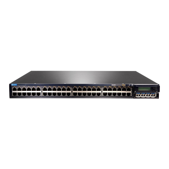
Page 28: Ex3200 Switches
Power over Ethernet (PoE) or only 8 ports equipped for PoE. All models provide ports that have 10/100/1000Base-T Gigabit Ethernet connectors and optional 1-gigabit small form-factor pluggable (SFP) transceivers, 10-gigabit small form-factor Copyright © 2010, Juniper Networks, Inc. -
Page 29: Uplink Modules
Related Topics EX3200 Switch Models on page 6 EX4200 Switch Models on page 6 Field-Replaceable Units in EX3200 and EX4200 Switches on page 18 Site Preparation Checklist for EX3200 and EX4200 Switches on page 87 Copyright © 2010, Juniper Networks, Inc. -
Page 30: Ex3200 Switch Models
48 Gigabit Ethernet All 48 ports 930 W EX4200-24F 24 small form-factor pluggable Not applicable 320 W (SFP) transceivers Related Topics EX3200 Switch Models on page 6 Front Panel of an EX4200 Switch on page 9 Copyright © 2010, Juniper Networks, Inc. -
Page 31: Chassis Physical Specifications For Ex3200 And Ex4200 Switches
The front panel of an EX3200 switch consists of the following components: 10/100/1000Base-T Gigabit Ethernet ports, some or all of which are enabled for Power over Ethernet (PoE) Uplink module ports—SFP, SFP+, or XFP ports (The uplink module is an optional feature.) Copyright © 2010, Juniper Networks, Inc. -
Page 32: Rear Panel Of An Ex3200 Switch
Removing an Uplink Module from an EX3200 or EX4200 Switch on page 177 Rear Panel of an EX3200 Switch The rear panel of the EX3200 switch consists of the following components: Protective earthing terminal Temperature shutdown LED Copyright © 2010, Juniper Networks, Inc. -
Page 33: Front Panel Of An Ex4200 Switch
Installing and Removing EX3200 and EX4200 Switch Hardware Components on page 131 Front Panel of an EX4200 Switch The front panel of an EX4200 switch consists of the following components: Network ports—depending on the switch model, either of: Copyright © 2010, Juniper Networks, Inc. -
Page 34: Figure 4: Ex4200 Switch With 48 Gigabit Ethernet Ports
Network Port LEDs in EX3200 and EX4200 Switches on page 21 Network Port Connector Pinout Information for an EX3200 or EX4200 Switch on page 40 LCD Panel in EX3200 and EX4200 Switches on page 13 Copyright © 2010, Juniper Networks, Inc. -
Page 35: Rear Panel Of An Ex4200 Switch
Front Panel of an EX4200 Switch on page 9 USB Port Specifications for an EX Series Switch on page 39 Cooling System and Airflow in an EX4200 Switch on page 33 Power Supply in EX3200 and EX4200 Switches on page 27 Copyright © 2010, Juniper Networks, Inc. - Page 36 Connecting Earth Ground to an EX Series Switch on page 141 Installing and Removing EX3200 and EX4200 Switch Hardware Components on page 131 Understanding Virtual Chassis Hardware Configuration on an EX4200 Switch on page 105 Copyright © 2010, Juniper Networks, Inc.
-
Page 37: Component Descriptions
You can configure the second line of the LCD panel to display a custom message. If the LCD panel is configured to display a custom message, the button and the Menu Enter button are disabled. See Configuring the LCD Panel on EX Series Switches (CLI Procedure). Copyright © 2010, Juniper Networks, Inc. -
Page 38: Lcd Panel Modes
Virtual Chassis port (VCP) status (for an EX4200 switch that is a member of a Virtual Chassis) Status of the power supply Status of the fan and temperature Version of Junos OS for EX Series switches loaded on the switch Copyright © 2010, Juniper Networks, Inc. -
Page 39: Lcd Panel Menus
SPD (speed) See “Network Port LEDs in EX3200 and EX4200 Switches” on page 21 for information on the Status LED modes. Press to exit the Idle menu and go to the Status menu. Menu Copyright © 2010, Juniper Networks, Inc. - Page 40 Show VCP status option. Menu If you do not want users to use Status menu options, disable the entire menu or individual menu options. See Configuring the LCD Panel on EX Series Switches (CLI Procedure). Copyright © 2010, Juniper Networks, Inc.
- Page 41 Field-Replaceable Units in EX3200 and EX4200 Switches on page 18 Connecting and Configuring an EX Series Switch (CLI Procedure) on page 165 Connecting and Configuring an EX Series Switch (J-Web Procedure) on page 167 Copyright © 2010, Juniper Networks, Inc.
-
Page 42: Field-Replaceable Units In Ex3200 And Ex4200 Switches
The power supply, fan tray, uplink module, and transceivers are hot-removable and hot-insertable: You can remove and replace them without powering off the switch or disrupting switch functions. NOTE: If you have a Juniper J-Care service contract, register any addition, change, or upgrade of hardware components at . Failure to https://www.juniper.net/customers/csc/management/updateinstallbase.jsp... -
Page 43: Chassis Status Leds In Ex3200 Switches
All three LEDs can be lit simultaneously. Related Topics Front Panel of an EX3200 Switch on page 7 Checking Active Alarms with the J-Web Interface Understanding Alarm Types and Severity Levels on EX Series Switches Copyright © 2010, Juniper Networks, Inc. -
Page 44: Chassis Status Leds In Ex4200 Switches
NOTE: The amber glow of the Alarm LED that indicates a minor alarm closely resembles the red glow that indicates a major alarm. All three LEDs can be lit simultaneously. Related Topics Front Panel of an EX4200 Switch on page 9 Copyright © 2010, Juniper Networks, Inc. -
Page 45: Network Port Leds In Ex3200 And Ex4200 Switches
Figure 14 on page 22 shows the location of the LEDs on the uplink module ports on the XFP uplink module. Figure 11: LEDs on the Network Ports on the Front Panel Figure 12: LEDs on the Uplink Module Ports on the SFP Uplink Module Copyright © 2010, Juniper Networks, Inc. -
Page 46: Figure 13: Leds On The Uplink Module Ports On The Sfp+ Uplink Module
State and Description Link/Activity Green Blinking—The port and the link are active, and there is link activity. On steadily—The port and the link are active, but there is no link activity. Off—The port is not active. Copyright © 2010, Juniper Networks, Inc. - Page 47 Table 8 on page 24 describes the Status LED. From the Idle menu of the LCD, use the button on the LCD panel to toggle between the ADM, DPX, POE, and SPD indicators. Enter Copyright © 2010, Juniper Networks, Inc.
-
Page 48: Table 8: Status Led On Network Ports In Ex3200 And Ex4200 Switches
A device that draws power from the port is connected to the port, but the device is not drawing any power from the port. Unlit—PoE is not enabled on the port. LED: SPD Copyright © 2010, Juniper Networks, Inc. -
Page 49: Management Port Leds In Ex3200 And Ex4200 Switches
The management port on EX3200 and EX4200 switches has two LEDs that indicate link/activity and port status (see Figure 15 on page 26 or Figure 16 on page 26). The management port is set to full-duplex and the speed is set to 100 Mbps. Copyright © 2010, Juniper Networks, Inc. -
Page 50: Figure 15: Leds On The Management Port On An Ex3200 Switch
See Rear Panel of an EX3200 Switch on page 8 for port location. See Rear Panel of an EX4200 Switch on page 11 for port location. Connecting an EX Series Switch to a Network for Out-of-Band Management on page 152 Copyright © 2010, Juniper Networks, Inc. -
Page 51: Power Supply In Ex3200 And Ex4200 Switches
NOTE: The A+ and B+ terminals are referred to as +RTN and A– and B– terminals are referred to as –48 V in “DC Power Wiring Sequence Warning for EX Series Switches” on page 244 and “DC Power Electrical Safety Guidelines for EX Series Switches” on page 240. Copyright © 2010, Juniper Networks, Inc. -
Page 52: Figure 17: 320 W Ac Power Supply In Ex3200 And Ex4200 Switches
Table 11 on page 28 lists the minimum power requirements for each model of EX3200 switch. The maximum power available to each PoE port is 15.4 W. Table 11: Minimum Power Requirements for an EX3200 Switch Model Number Number of PoE-enabled Ports Minimum Power Requirement EX3200-24T 320 W Copyright © 2010, Juniper Networks, Inc. -
Page 53: Table 12: Minimum Power Requirements For An Ex4200 Switch
LEDs on the power supply, command output, show chassis and messages on the LCD—to indicate that the power supply is functioning normally. Ignore error indicators that appear during the first 60 seconds. Copyright © 2010, Juniper Networks, Inc. -
Page 54: Ac Power Supply Leds In Ex3200 And Ex4200 Switches
DC Power Supply LEDs in EX3200 and EX4200 Switches The DC power supply in an EX3200 or EX4200 switch is on the rear panel. Table 14 on page 31 describes the LEDs on the DC power supplies in EX3200 and EX4200 switches. Copyright © 2010, Juniper Networks, Inc. -
Page 55: Cooling System And Airflow In An Ex3200 Switch
The cooling system in an EX3200 switch consists of a field-replaceable unit (FRU) fan tray with one fan (see Figure 20 on page 32). The fan tray is located at the rear of the chassis and provides side-to-rear chassis cooling (see Figure 21 on page 32). Copyright © 2010, Juniper Networks, Inc. -
Page 56: Figure 20: Fan Tray Used In An Ex3200 Switch
Rear Panel of an EX3200 Switch on page 8 Prevention of Electrostatic Discharge Damage on EX Series Switches on page 236 Installing a Fan Tray in an EX3200 or EX4200 Switch on page 133 Copyright © 2010, Juniper Networks, Inc. -
Page 57: Cooling System And Airflow In An Ex4200 Switch
Temperature sensors in the chassis monitor the temperature within the chassis. The system raises an alarm if the fan fails or if the temperature inside the chassis rises above permitted levels. If the temperature inside the chassis rises above the threshold, the Copyright © 2010, Juniper Networks, Inc. -
Page 58: Uplink Modules In Ex3200 And Ex4200 Switches
SFP+ uplink module configured to operate in the 10-gigabit mode at the other end. This topic describes: SFP Uplink Module on page 35 SFP+ Uplink Module on page 35 XFP Uplink Module on page 37 Copyright © 2010, Juniper Networks, Inc. -
Page 59: Sfp Uplink Module
If the operating mode and the configured mode for an SFP+ uplink module are different, it is shown in the output of show chassis pic fpc-slot slot number pic-slot 1 Figure 25 on page 36 shows the SFP+ uplink module. Copyright © 2010, Juniper Networks, Inc. -
Page 60: Figure 25: Sfp+ Uplink Module
For example, if you install an SFP+ transceiver in port 2 on the uplink module ( ), then is disabled. The disabled port ge-0/1/3 ge-0/0/23 is not listed in the output of show interface commands. Copyright © 2010, Juniper Networks, Inc. -
Page 61: Xfp Uplink Module
Virtual Chassis Access Switch and a Virtual Chassis Distribution Switch Installing an Uplink Module in an EX3200 or EX4200 Switch on page 135 Troubleshooting Uplink Module Installation or Replacement on EX3200 and EX4200 Switches on page 194 Copyright © 2010, Juniper Networks, Inc. - Page 62 Complete Hardware Guide for EX3200 and EX4200 Ethernet Switches Copyright © 2010, Juniper Networks, Inc.
-
Page 63: Component Specifications
RE-USB-4G-S CAUTION: Any USB memory product not listed as supported for EX Series switches has not been tested by Juniper Networks. The use of any unsupported USB memory product could expose your EX Series switch to unpredictable behavior. Juniper Networks Technical Assistance Center (JTAC) can provide only limited support for issues related to unsupported hardware. -
Page 64: Table 15: Network Port Connector Pinout Information For An Ex3200 Or Ex4200
Negative Vport (in PoE models) TRP2+ Transmit/receive data pair 2 Positive Vport (in PoE models) TRP3+ Transmit/receive data pair 3 TRP3- Transmit/receive data pair 3 TRP2- Transmit/receive data pair 2 Positive Vport (in PoE models) Copyright © 2010, Juniper Networks, Inc. -
Page 65: Console Port Connector Pinout Information For An Ex Series Switch
Signal Ground Signal ground Signal Ground Signal ground RxD Input Receive data CD Input Data carrier detect CTS Input Clear to send Related Topics See Rear Panel of an EX2200 Switch for port location. Copyright © 2010, Juniper Networks, Inc. -
Page 66: Table 17: Management Port Connector Pinout Information For Ex3200 And Ex4200 Switches
See Rear Panel of an EX3200 Switch on page 8 for port location. See Rear Panel of an EX4200 Switch on page 11 for port location. Connecting an EX Series Switch to a Network for Out-of-Band Management on page 152 Copyright © 2010, Juniper Networks, Inc. -
Page 67: Optical Interface Support In Ex3200 And Ex4200 Switches
This topic describes the optical interfaces supported for those transceivers. It also lists the copper interface supported for the SFP transceivers. NOTE: Use only optical transceivers and optical connectors purchased from Juniper Networks for your EX Series switch. The Gigabit Ethernet SFP, SFP+, or XFP transceivers installed in EX3200 or EX4200... -
Page 68: Table 18: Optical Interface Support And Copper Interface Support For Gigabit Ethernet Sfp Transceivers In Ex3200 And Ex4200 Switches
Maximum Input Power – Fiber Type Copper Core/Cladding Size – Modal Bandwidth – Distance 100 m (328 ft) DOM Support Not available Software required Junos OS for EX Series switches, Release 9.0 or later Copyright © 2010, Juniper Networks, Inc. - Page 69 500 MHz/km Distance 220 m 275 m 500 m 550 m (722 ft) (902 ft) (1640 ft) (1804 ft) DOM Support Available Software required Junos OS for EX Series switches, Release 9.0 or later Copyright © 2010, Juniper Networks, Inc.
- Page 70 Maximum Input Power –3 dBm Fiber Type Core/Cladding Size 9/125 µm Modal Bandwidth – Distance 10 km (6.2 miles) DOM Support Available Software required Junos OS for EX Series switches, Release 9.0 or later Copyright © 2010, Juniper Networks, Inc.
- Page 71 Maximum Input Power –3 dBm Fiber Type Core/Cladding Size 9/125 µm Modal Bandwidth – Distance 10 km (6.2 miles) DOM Support Available Software required Junos OS for EX Series switches, Release 9.4 or later Copyright © 2010, Juniper Networks, Inc.
- Page 72 Maximum Input Power –3 dBm Fiber Type Core/Cladding Size 9/125 µm Modal Bandwidth – Distance 10 km (6.2 miles) DOM Support Available Software required Junos OS for EX Series switches, Release 9.4 or later Copyright © 2010, Juniper Networks, Inc.
- Page 73 Maximum Input Power –21 dBm Fiber Type Core/Cladding Size 9/125 µm Modal Bandwidth – Distance 10 km (6.2 miles) DOM Support Available Software required Junos OS for EX Series switches, Release 9.5 or later Copyright © 2010, Juniper Networks, Inc.
- Page 74 Maximum Input Power –21 dBm Fiber Type Core/Cladding Size 9/125 µm Modal Bandwidth – Distance 10 km (6.2 miles) DOM Support Available Software required Junos OS for EX Series switches, Release 9.5 or later Copyright © 2010, Juniper Networks, Inc.
- Page 75 Maximum Input Power –23 dBm Fiber Type Core/Cladding Size 9/125 µm Modal Bandwidth – Distance 40 km (24.8 miles) DOM Support Available Software required Junos OS for EX Series switches, Release 9.5 or later Copyright © 2010, Juniper Networks, Inc.
- Page 76 Maximum Input Power –23 dBm Fiber Type Core/Cladding Size 9/125 µm Modal Bandwidth – Distance 40 km (24.8 miles) DOM Support Available Software required Junos OS for EX Series switches, Release 9.5 or later Copyright © 2010, Juniper Networks, Inc.
- Page 77 Maximum Input Power –3 dBm Fiber Type Core/Cladding Size 9/125 µm Modal Bandwidth – Distance 40 km (24.8 miles) DOM Support Available Software required Junos OS for EX Series switches, Release 9.4 or later Copyright © 2010, Juniper Networks, Inc.
- Page 78 Maximum Input Power –3 dBm Fiber Type Core/Cladding Size 9/125 µm Modal Bandwidth – Distance 70 km (43.5 miles) DOM Support Available Software required Junos OS for EX Series switches, Release 9.0 or later Copyright © 2010, Juniper Networks, Inc.
-
Page 79: Table 19: Optical Interface Support For Fast Ethernet Sfp Transceivers In Ex3200 And Ex4200 Switches
Fiber Type Core/Cladding Size 62.5/125 µm Fiber Grade FDDI/OM1 Modal Bandwidth 500 Mhz/km Distance 2 km (1.2 miles) DOM Support Not available Software required Junos OS for EX Series switches, Release 9.2 or later Copyright © 2010, Juniper Networks, Inc. - Page 80 Maximum Input Power –8 dBm Fiber Type Core/Cladding Size 9/125 µm Modal Bandwidth – Distance 10 km (6.2 miles) DOM Support Not available Software required Junos OS for EX Series switches, Release 9.5 or later Copyright © 2010, Juniper Networks, Inc.
- Page 81 Maximum Input Power –8 dBm Fiber Type Core/Cladding Size 9/125 µm Modal Bandwidth – Distance 20 km (12.4 miles) DOM Support Not available Software required Junos OS for EX Series switches, Release 9.3 or later Copyright © 2010, Juniper Networks, Inc.
- Page 82 Maximum Input Power –8 dBm Fiber Type Core/Cladding Size 9/125 µm Modal Bandwidth – Distance 20 km (12.4 miles) DOM Support Not available Software required Junos OS for EX Series switches, Release 9.3 or later Copyright © 2010, Juniper Networks, Inc.
- Page 83 Maximum Input Power –8 dBm Fiber Type Core/Cladding Size 9/125 µm Modal Bandwidth – Distance 40 km (24.8 miles) DOM Support Not available Software required Junos OS for EX Series switches, Release 10.0 or later Copyright © 2010, Juniper Networks, Inc.
- Page 84 Maximum Input Power –8 dBm Fiber Type Core/Cladding Size 9/125 µm Modal Bandwidth – Distance 80 km (49.7 miles) DOM Support Not available Software required Junos OS for EX Series switches, Release 10.0 or later Copyright © 2010, Juniper Networks, Inc.
-
Page 85: Table 20: Optical Interface Support For Gigabit Ethernet Sfp+ Transceivers In
Modal Bandwidth 1500 MHz/km MHz/km MHz/km Distance 10 m 30 m 100 m (32.8 ft) (98.4 ft) (328 ft) DOM Support Available Software required Junos OS for EX Series switches, Release 10.2 or later Copyright © 2010, Juniper Networks, Inc. - Page 86 26 m 33 m 66 m 82 m 300 m (85 ft) (108 ft) (216 ft) (269 ft) (984 ft) DOM Support Available Software required Junos OS for EX Series switches, Release 9.4 or later Copyright © 2010, Juniper Networks, Inc.
- Page 87 FDDI/OM1 Modal Bandwidth MHz/km MHz/km MHz/km Distance 220 m 220 m 220 m (722 ft) (722 ft) (722 ft) DOM Support Available Software required Junos OS for EX Series switches, Release 9.5 or later Copyright © 2010, Juniper Networks, Inc.
- Page 88 Maximum Input Power 0.5 dBm Fiber Type Core/Cladding Size 9/125 µm Modal Bandwidth – Distance 10 km (6.2 miles) DOM Support Available Software required Junos OS for EX Series switches, Release 9.4 or later Copyright © 2010, Juniper Networks, Inc.
- Page 89 Maximum Input Power –1 dBm Fiber Type Core/Cladding Size 9/125 µm Modal Bandwidth – Distance 40 km (24.8 miles) DOM Support Available Software required Junos OS for EX Series switches, Release 10.3 or later Copyright © 2010, Juniper Networks, Inc.
-
Page 90: Table 21: Optical Interface Support For Gigabit Ethernet Xfp Transceivers In
26 m 33 m 66 m 82 m 300 m (85 ft) (108 ft) (216 ft) (269 ft) (984 ft) DOM Support Available Software required Junos OS for EX Series switches, Release 9.0 or later Copyright © 2010, Juniper Networks, Inc. - Page 91 Maximum Input Power 0.5 dBm Fiber Type Core/Cladding Size 9/125 µm Modal Bandwidth – Distance 10 km (6.2 miles) DOM Support Available Software required Junos OS for EX Series switches, Release 9.0 or later Copyright © 2010, Juniper Networks, Inc.
- Page 92 Maximum Input Power –1 dBm Fiber Type Core/Cladding Size 9/125 µm Modal Bandwidth – Distance 40 km (24.8 miles) DOM Support Available Software required Junos OS for EX Series switches, Release 9.0 or later Copyright © 2010, Juniper Networks, Inc.
-
Page 93: Sfp+ Direct Attach Cables For Ex Series Switches
Twinax cables, are suitable for in-rack connections between servers and switches. They are suitable for short distances up to 7 m, making them ideal for highly cost-effective networking connectivity within a rack and between adjacent racks. Copyright © 2010, Juniper Networks, Inc. -
Page 94: Cable Specifications
Standards Supported by These Cables on page 73 Cable Specifications Juniper Networks SFP+ direct attach cables are available in four lengths: 1 m (3.3 ft)—Supported on EX3200, EX4200, EX4500, and EX8200 switches 3 m (9.9 ft)—Supported on EX3200, EX4200, EX4500, and EX8200 switches 5 m (16.4 ft)—Supported on EX3200, EX4200, and EX8200 switches... -
Page 95: Table 22: Sfp+ Direct Attach Cable Specifications
C to 85 Cable type Twinax Wire AWG 30 AWG Minimum cable bend radius 1 in. Cable characteristic impedance 100 ohms Crosstalk between pairs 2% maximum Time delay 1.31 nsec/ft Length 3 m (9.9 ft) Copyright © 2010, Juniper Networks, Inc. - Page 96 C to 85 Cable type Twinax Wire AWG 24 AWG Minimum cable bend radius 2 in. Cable characteristic impedance 100 ohms Crosstalk between pairs 2% maximum Time delay 1.31 nsec/ft Length 7 m (23 ft) Copyright © 2010, Juniper Networks, Inc.
-
Page 97: Standards Supported By These Cables
You can also use optional uplink module ports to connect members of a Virtual Chassis across multiple wiring closets. Table 23: Uplink Modules Connector Pinout Information for EX3200 and EX4200 Switches Pin Number Pin Name Copyright © 2010, Juniper Networks, Inc. -
Page 98: Switches
Complete Hardware Guide for EX3200 and EX4200 Ethernet Switches Table 23: Uplink Modules Connector Pinout Information for EX3200 and EX4200 Switches (continued) Pin Number Pin Name Uplink_I2C_SCK Uplink_PD POWER (12V) XAUI0_RX0N XAUI0_RX2N Uplink_P25_LED2 XAUI1_RX0N Uplink_P27_LED2 XAUI1_RX2N SRX28N Uplink_XAUI_XMDIO SRX26N Copyright © 2010, Juniper Networks, Inc. - Page 99 Table 23: Uplink Modules Connector Pinout Information for EX3200 and EX4200 Switches (continued) Pin Number Pin Name SGMIIRXN Uplink_I2C_Rst Uplink_Intr Uplink_Pwr_En Uplink_P26_LED0 POWER (12V) POWER (12V) XAUI0_RX0P XAUI0_RX2P XAUI1_RX0P XAUI1_RX2P SRX28P SRX26P SGMIIRXP CPU_UPLINK_MDC Copyright © 2010, Juniper Networks, Inc.
- Page 100 Complete Hardware Guide for EX3200 and EX4200 Ethernet Switches Table 23: Uplink Modules Connector Pinout Information for EX3200 and EX4200 Switches (continued) Pin Number Pin Name Uplink_I2C_SDA CPU_UPLINK_MDIO Uplink_P26_LED1 UPLNK_PWR_OK POWER (12V) XAUI0_TX1N XAUI0_TX3N XAUI1_TX1N XAUI1_TX3N STX27N STX25N Uplink_Rst Uplink_Status_LED0 Copyright © 2010, Juniper Networks, Inc.
- Page 101 Table 23: Uplink Modules Connector Pinout Information for EX3200 and EX4200 Switches (continued) Pin Number Pin Name POWER (12V) XAUI0_TX0N XAUI0_TX1P XAUI0_TX2N XAUI0_TX3P XAUI1_TX0N XAUI1_TX1P XAUI1_TX2N XAUI1_TX3P STX28N STX27P STX26N STX25P SGMIITXN Uplink_Hotswap_LED Uplink_Spare_Intr Uplink_Status_LED1 Uplink_P27_LED0 POWER (12V) POWER (12V) Copyright © 2010, Juniper Networks, Inc.
- Page 102 Complete Hardware Guide for EX3200 and EX4200 Ethernet Switches Table 23: Uplink Modules Connector Pinout Information for EX3200 and EX4200 Switches (continued) Pin Number Pin Name XAUI0_TX0P XAUI0_TX2P XAUI1_TX0P XAUI_TX2P STX28P STX26P SGMIITXP Uplink_Expander_Intr Uplink_P27_LED1 POWER (12V) XAUI0_RX1N Copyright © 2010, Juniper Networks, Inc.
- Page 103 Chapter 3: Component Specifications Table 23: Uplink Modules Connector Pinout Information for EX3200 and EX4200 Switches (continued) Pin Number Pin Name XAUI0_RX3N XAUI1_RX1N XAUI1_RX3N SRX27N SRX25N Uplink_P25_LED0 POWER (12V) Uplink_PD_Loopback XAUI0_RX1P XAUI0_RX3P Uplink_P26_ LED2 XAUI1_RX1P Copyright © 2010, Juniper Networks, Inc.
- Page 104 Complete Hardware Guide for EX3200 and EX4200 Ethernet Switches Table 23: Uplink Modules Connector Pinout Information for EX3200 and EX4200 Switches (continued) Pin Number Pin Name Uplink_P28_ LED2 XAUI1_RX3P SRX27P Uplink_XAUI_MDC SRX25P Serial_RX Uplink_P25_LED1 Uplink_P28_LED0 POWER (12V) POWER (12V) Copyright © 2010, Juniper Networks, Inc.
-
Page 105: Virtual Chassis Ports Connector Pinout Information For Ex4200 Switches
Chassis. The cable is provided with the switch. Table 24 on page 81 provides the Virtual Chassis ports (VCPs) connector pinout information. Table 24: Virtual Chassis Ports (VCPs) Connector Pinout Information Pin Number Pin Name P1TXP0 P1TXN0 Copyright © 2010, Juniper Networks, Inc. - Page 106 Complete Hardware Guide for EX3200 and EX4200 Ethernet Switches Table 24: Virtual Chassis Ports (VCPs) Connector Pinout Information (continued) Pin Number Pin Name P1TXP1 P1TXN1 P1TXP2 P1TXN2 P1TXP3 P1TXN3 P2TXP0 P2TXN0 P2TXP1 P2TXN1 Copyright © 2010, Juniper Networks, Inc.
- Page 107 Chapter 3: Component Specifications Table 24: Virtual Chassis Ports (VCPs) Connector Pinout Information (continued) Pin Number Pin Name P2TXP2 P2TXN2 P2TXP3 P2TXN3 P1RXP0 P1RXN0 P1RXP1 P1RXN1 P1RXP2 P1RXN2 P1RXP3 P1RXN3 Copyright © 2010, Juniper Networks, Inc.
- Page 108 Planning the Virtual Chassis on page 106 Understanding Virtual Chassis Components Understanding Virtual Chassis Hardware Configuration on an EX4200 Switch on page 105 Connecting a Virtual Chassis Cable to an EX4200 Switch on page 139 Copyright © 2010, Juniper Networks, Inc.
-
Page 109: Planning For Switch Installation
Planning for Switch Installation Site Preparation on page 87 Mounting and Clearance Requirements on page 93 Cable Specifications on page 99 Planning Power Requirements on page 101 Planning the Virtual Chassis on page 105 Copyright © 2010, Juniper Networks, Inc. - Page 110 Complete Hardware Guide for EX3200 and EX4200 Ethernet Switches Copyright © 2010, Juniper Networks, Inc.
-
Page 111: Site Preparation
“Power Specifications for EX3200 requirements. and EX4200 Switches” on page 101 Hardware Configuration Choose the number and types of switches you “EX3200 and EX4200 Switches want to install. Hardware Overview” on page 3 Rack or Cabinet Copyright © 2010, Juniper Networks, Inc. - Page 112 General Safety Guidelines and Warnings for EX Series Switches on page 207 General Site Guidelines for EX Series Switches on page 89 Installing and Connecting an EX3200 or EX4200 Switch on page 117 Mounting an EX3200 or EX4200 Switch on page 120 Copyright © 2010, Juniper Networks, Inc.
-
Page 113: General Site Guidelines For Ex Series Switches
Table 26 on page 90 describes the factors you must consider while planning the electrical wiring at your site. WARNING: It is particularly important to provide a properly grounded and shielded environment and to use electrical surge-suppression devices. Copyright © 2010, Juniper Networks, Inc. -
Page 114: Environmental Requirements And Specifications For Ex Series Switches
DC Power Supply in an EX8200 Switch Environmental Requirements and Specifications for EX Series Switches The switch must be installed in a rack or cabinet housed in a dry, clean, well-ventilated, and temperature-controlled environment. Copyright © 2010, Juniper Networks, Inc. -
Page 115: Table 27: Ex Series Switch Environmental Tolerances
EX4200 Switches on page 96 Clearance Requirements for Airflow and Hardware Maintenance for EX4500 Switches Clearance Requirements for Airflow and Hardware Maintenance for an EX8208 Switch Clearance Requirements for Airflow and Hardware Maintenance for an EX8216 Switch Copyright © 2010, Juniper Networks, Inc. - Page 116 Complete Hardware Guide for EX3200 and EX4200 Ethernet Switches Copyright © 2010, Juniper Networks, Inc.
-
Page 117: Mounting And Clearance Requirements
The holes in the mounting brackets are spaced at 1 U (1.75 in. or 4.45 cm), so that the switch can spacing be mounted in any rack that provides holes spaced at that distance. Copyright © 2010, Juniper Networks, Inc. -
Page 118: Cabinet Requirements For Ex3200 And Ex4200 Switches
You can mount the switch in a cabinet that contains a 19-in. rack. Cabinet requirements consist of: Cabinet size Clearance requirements Cabinet airflow requirements Table 29 on page 95 provides the cabinet requirements and specifications for the switch. Copyright © 2010, Juniper Networks, Inc. -
Page 119: Wall
You can install the switch on a desktop or wall. When choosing a location, allow at least 6 in. (15.2 cm) of clearance between the front and back of the chassis and adjacent equipment or walls. Copyright © 2010, Juniper Networks, Inc. -
Page 120: Clearance Requirements For Airflow And Hardware Maintenance For Ex3200 And Ex4200 Switches
Insert the screws into wall studs wherever possible to provide added support for the chassis. Use the wall-mount kit from Juniper Networks to mount the switch on a wall. The wall-mount kit is not part of the standard package and needs to be ordered separately. -
Page 121: Figure 28: Airflow Through The Ex3200 Switch Chassis
NEBS GR-63 recommends that you allow at least 30 in. (76.2 cm) in front of the rack or cabinet and 24 in. (61 cm) behind the rack or cabinet. Figure 28: Airflow Through the EX3200 Switch Chassis Copyright © 2010, Juniper Networks, Inc. -
Page 122: Figure 29: Airflow Through The Ex4200 Switch Chassis
General Site Guidelines for EX Series Switches on page 89 Rack-Mounting and Cabinet-Mounting Warnings for EX Series Switches on page 221 Cooling System and Airflow in an EX3200 Switch on page 31 Cooling System and Airflow in an EX4200 Switch on page 33 Copyright © 2010, Juniper Networks, Inc. -
Page 123: Cable Specifications
Management Port Connector Pinout Information for an EX3200 or EX4200 Switch on page 42 Console Port Connector Pinout Information for an EX Series Switch on page 41 Rear Panel of an EX3200 Switch on page 8 Rear Panel of an EX4200 Switch on page 11 Copyright © 2010, Juniper Networks, Inc. - Page 124 Complete Hardware Guide for EX3200 and EX4200 Ethernet Switches Copyright © 2010, Juniper Networks, Inc.
-
Page 125: Planning Power Requirements
Table 31: DC Power Supply Electrical Specifications for EX3200 and EX4200 Switches Item Specification DC input voltage 36 through 72 VDC DC input current 7 A maximum Power supply output 190 W Output holdup time 1 ms minimum Copyright © 2010, Juniper Networks, Inc. -
Page 126: Ac Power Cord Specifications For Ex3200 And Ex4200 Switches
250 VAC, 10 A, 50 Hz AS/NZ 3112 China 250 VAC, 10 A, 50 Hz GB2099 and GB1002 Europe (except Italy, Switzerland, and 250 VAC, 10 A, 50 Hz CEE (7) VII United Kingdom) Copyright © 2010, Juniper Networks, Inc. -
Page 127: Figure 30: Ac Plug Types
General Safety Guidelines and Warnings for EX Series Switches on page 207 General Electrical Safety Guidelines and Warnings for EX Series Switches on page 235 Prevention of Electrostatic Discharge Damage on EX Series Switches on page 236 Copyright © 2010, Juniper Networks, Inc. - Page 128 Complete Hardware Guide for EX3200 and EX4200 Ethernet Switches Copyright © 2010, Juniper Networks, Inc.
-
Page 129: Switch
Procedure) on page 109 Understanding Virtual Chassis Hardware Configuration on an EX4200 Switch Virtual Chassis is a feature in Juniper Networks EX4200 Ethernet Switches that allows you to interconnect two or more EX4200 switches, enabling them to operate as a unified single high bandwidth switch. -
Page 130: Planning The Virtual Chassis
Understanding Virtual Chassis Hardware Configuration on an EX4200 Switch on page 105 Virtual Chassis Cabling Configuration Examples for EX4200 Switches on page 107 Clearance Requirements for Airflow and Hardware Maintenance for EX3200 and EX4200 Switches on page 96 Copyright © 2010, Juniper Networks, Inc. -
Page 131: Virtual Chassis Cabling Configuration Examples For Ex4200 Switches
Virtual Chassis cables and one long Virtual Chassis cable. Figure 31: EX4200 Switches Mounted on a Single Rack and Connected in a Ring Topology Using Short and Long Cables: Option 1 Copyright © 2010, Juniper Networks, Inc. -
Page 132: Figure 32: Ex4200 Switches Mounted On A Single Rack And Connected In A Ring
Virtual Chassis cables. Figure 34: EX4200 Switches Mounted on Adjacent Racks and Connected in a Ring Topology Using Medium and Long Cables: Option 1 Copyright © 2010, Juniper Networks, Inc. -
Page 133: Procedure)
You can specify the role of the new member switch when you add its serial number in the Virtual Chassis configuration file. The parameters specified in the master Virtual Chassis configuration Copyright © 2010, Juniper Networks, Inc. -
Page 134: Adding A New Switch From A Different Wiring Closet To An Existing Virtual Chassis Configuration
If you are expanding a preprovisioned configuration, made a note of the serial number (on the back of the switch). You will need to edit the Virtual Chassis configuration to include the serial number of the new member switch. Copyright © 2010, Juniper Networks, Inc. - Page 135 ID that is higher than 0 (1 through 9), because there is already at least one member of the Virtual Chassis configuration. NOTE: If you are using a preprovisioned configuration, the member ID is automatically assigned to the member's serial number in the configuration file. Copyright © 2010, Juniper Networks, Inc.
-
Page 136: Adding A New Switch To An Existing Preprovisioned Virtual Chassis Configuration Using Autoprovisioning
Power on the new member switch. Confirm that the new member switch is now included in the Virtual Chassis configuration by checking the front-panel display for the member ID. It should display Copyright © 2010, Juniper Networks, Inc. - Page 137 Example: Configuring Automatic Software Update on Virtual Chassis Member Switches Monitoring Virtual Chassis Configuration Status and Statistics Replacing a Member Switch of a Virtual Chassis Configuration (CLI Procedure) on page 183 Reverting to the Default Factory Configuration for the EX Series Switch Copyright © 2010, Juniper Networks, Inc.
- Page 138 Complete Hardware Guide for EX3200 and EX4200 Ethernet Switches Copyright © 2010, Juniper Networks, Inc.
-
Page 139: Installing And Connecting The Switch And Switch Components
PART 3 Installing and Connecting the Switch and Switch Components Installing the Switch on page 117 Installing Switch Components on page 131 Connecting the Switch on page 141 Performing Initial Configuration on page 161 Copyright © 2010, Juniper Networks, Inc. - Page 140 Complete Hardware Guide for EX3200 and EX4200 Ethernet Switches Copyright © 2010, Juniper Networks, Inc.
-
Page 141: Installing The Switch
“Mounting an EX3200 or EX4200 Switch on a Desk or Other Level Surface” on page 121 (using the rubber feet provided) “Mounting an EX3200 or EX4200 Switch on a Wall” on page 128 (using the separately orderable wall-mount kit) Copyright © 2010, Juniper Networks, Inc. -
Page 142: Unpacking An Ex3200 Or Ex4200 Switch
Open the top flaps on the shipping carton. Remove the accessory box and verify the contents against the parts inventory on the label attached to the carton. Pull out the packing material holding the switch in place. Copyright © 2010, Juniper Networks, Inc. -
Page 143: Figure 36: Unpacking An Ex3200 Or Ex4200 Switch
Power supply (preinstalled if your system order includes a 320 W AC power supply; not preinstalled if your system order includes a 600 W AC power supply, a 930 W AC power supply, or a 190 W DC power supply) Power cord retainer Mounting brackets Mounting screws Rubber feet Copyright © 2010, Juniper Networks, Inc. -
Page 144: Mounting An Ex3200 Or Ex4200 Switch
Mounting an EX3200 or EX4200 Switch in a Recessed Position in a Rack or Cabinet on page 128 Mounting an EX3200 or EX4200 Switch on a Desk or Other Level Surface on page 121 Mounting an EX3200 or EX4200 Switch on a Wall on page 128 Copyright © 2010, Juniper Networks, Inc. -
Page 145: Mounting An Ex3200 Or Ex4200 Switch On A Desk Or Other Level Surface
Turn the chassis right side up on the desk or the level surface. If it is an EX4200-24F switch, we recommend you insert dust covers in unused SFP ports. Figure 37: Attaching Rubber Feet to an EX3200 or EX4200 Switch Chassis Copyright © 2010, Juniper Networks, Inc. -
Page 146: Mounting An Ex3200 Or Ex4200 Switch On Two Posts In A Rack Or Cabinet
Screws to secure the chassis to the rack (not provided) 2-in.-recess front brackets if you will mount the switch in a recessed position (brackets are from the separately orderable four-post rack-mount kit). Dust covers for ports (for EX4200-24F switches only; optional) Copyright © 2010, Juniper Networks, Inc. -
Page 147: Figure 38: Attaching The Mounting Bracket Along The Front Of The Switch
Align the bottom hole in both the mounting brackets with a hole in each rack rail, making sure the chassis is level. See Figure 39 on page 124. Copyright © 2010, Juniper Networks, Inc. -
Page 148: Mounting An Ex3200 Or Ex4200 Switch On Four Posts In A Rack Or Cabinet
You can mount the switch on two posts in either a two-post rack or a four-post rack by using the mounting brackets provided with the switch. See “Mounting an EX3200 or EX4200 Switch on Two Posts in a Rack or Cabinet” on page 122. Copyright © 2010, Juniper Networks, Inc. - Page 149 CAUTION: If you are mounting multiple units on a rack, mount the heaviest unit at the bottom of the rack and mount the other units from the bottom of the rack to the top in decreasing order of the weight of the units. Copyright © 2010, Juniper Networks, Inc.
-
Page 150: Figure 40: Attaching The Front Bracket To The Side-Rail Bracket
Align the bottom hole in both the mounting brackets with a hole in each rack rail, making sure the chassis is level. See Figure 42 on page 127. Copyright © 2010, Juniper Networks, Inc. -
Page 151: Figure 42: Mounting The Switch To The Front Posts In A Rack
Connecting Earth Ground to an EX Series Switch on page 141 Connecting AC Power to an EX3200 or EX4200 Switch on page 147 Connecting DC Power to an EX3200 or EX4200 Switch on page 149 Copyright © 2010, Juniper Networks, Inc. -
Page 152: Mounting An Ex3200 Or Ex4200 Switch In A Recessed Position In A Rack Or Cabinet
“Chassis Lifting Guidelines for EX3200 and EX4200 Switches” on page 220. Remove the switch from the shipping carton (see “Unpacking an EX3200 or EX4200 Switch” on page 118). Ensure that you have the following parts and tools available: Copyright © 2010, Juniper Networks, Inc. -
Page 153: Figure 44: Attaching Wall-Mount Brackets To An Ex3200 Or Ex4200 Switch
If you are mounting two switches together, line the second switch on top of the first and attach it to the mounting brackets using two wall-mount bracket screws on each side (see Figure 45 on page 130). Copyright © 2010, Juniper Networks, Inc. -
Page 154: Figure 45: Mounting An Ex3200 Or Ex4200 Switch On A Wall
Connecting and Configuring an EX Series Switch (CLI Procedure) on page 165 Connecting and Configuring an EX Series Switch (J-Web Procedure) on page 167 Wall-Mounting Warning for EX3200 and EX4200 Switches on page 225 Copyright © 2010, Juniper Networks, Inc. -
Page 155: Installing Switch Components
Fan Tray in an EX3200 or EX4200 Switch” on page 133. To remove a fan tray from an EX3200 or EX4200 switch, follow instructions in “Removing a Fan Tray from an EX3200 or EX4200 Switch” on page 176. Copyright © 2010, Juniper Networks, Inc. -
Page 156: Installing A Power Supply In An Ex3200 Or Ex4200 Switch
The handle on the 190 W DC power supply runs across the faceplate. Push the locking lever up to its highest position (this action might pull the power supply in). Tighten the locking lever screw by using the screwdriver. Copyright © 2010, Juniper Networks, Inc. -
Page 157: Installing A Fan Tray In An Ex3200 Or Ex4200 Switch
Figure 46: Installing a Power Supply in an EX3200 or EX4200 Switch NOTE: Each power supply must be connected to a dedicated power source outlet. NOTE: If you have a Juniper J-Care service contract, register any addition, change, or upgrade of hardware components at https://www.juniper.net/customers/csc/management/updateinstallbase.jsp... -
Page 158: Figure 47: Installing A Fan Tray In An Ex3200 Switch
131 Cooling System and Airflow in an EX3200 Switch on page 31 Cooling System and Airflow in an EX4200 Switch on page 33 Field-Replaceable Units in EX3200 and EX4200 Switches on page 18 Copyright © 2010, Juniper Networks, Inc. -
Page 159: Installing An Uplink Module In An Ex3200 Or Ex4200 Switch
Ensure that you have the following parts and tools available: Electrostatic discharge (ESD) grounding strap (If a grounding strap is not available, follow the alternative grounding method described in Step 1 of the following procedure.) Cross-head screwdriver (provided in the uplink module kit) Copyright © 2010, Juniper Networks, Inc. -
Page 160: Figure 49: Installing An Uplink Module In An Ex3200 Or Ex4200 Switch
NOTE: If the switch does not detect the uplink module, see “Troubleshooting Uplink Module Installation or Replacement on EX3200 and EX4200 Switches” on page 194. Figure 49: Installing an Uplink Module in an EX3200 or EX4200 Switch Copyright © 2010, Juniper Networks, Inc. -
Page 161: Installing A Transceiver In An Ex Series Switch
Chapter 10: Installing Switch Components NOTE: If you have a Juniper J-Care service contract, register any addition, change, or upgrade of hardware components at . Failure to https://www.juniper.net/customers/csc/management/updateinstallbase.jsp do so can result in significant delays if you need replacement parts. This note applies if you change the type of power supply or add a new type of uplink module. -
Page 162: Figure 50: Installing A Transceiver In An Ex Series Switch
Fiber-optic transceivers and fiber-optic cables connected to transceivers emit laser light that can damage your eyes. Figure 50: Installing a Transceiver in an EX Series Switch Related Topics Removing a Transceiver from an EX Series Switch on page 179 Copyright © 2010, Juniper Networks, Inc. -
Page 163: Connecting A Virtual Chassis Cable To An Ex4200 Switch
Chassis port and slide it in gently until it is fully seated. Slide the locking cover over the Virtual Chassis cable connector. Tighten the screws on the locking cover by using the cross-head screwdriver. Copyright © 2010, Juniper Networks, Inc. -
Page 164: Figure 51: Connecting A Virtual Chassis Cable To An Ex4200 Switch
Understanding Virtual Chassis Hardware Configuration on an EX4200 Switch on page 105 Understanding Virtual Chassis Components Planning the Virtual Chassis on page 106 Virtual Chassis Ports Connector Pinout Information for EX4200 Switches on page 81 Copyright © 2010, Juniper Networks, Inc. -
Page 165: Connecting The Switch
Figure 52: Connecting a Grounding Cable to an EX Series Switch Before you connect earth ground to the protective earthing terminal of an EX Series switch, ensure that a licensed electrician has attached an appropriate grounding lug to the grounding cable. Copyright © 2010, Juniper Networks, Inc. -
Page 166: Connecting Earth Ground To An Ex2200 Or Ex3200 Switch
NOTE: Some early models of EX3200 switches require 10-24x.25-in. screws rather than 10-32x.25-in. screws. If the Juniper Networks product number on the label next to the protective earthing terminal is from 750-021xxx through 750-030xxx, the switch requires 10-24x.25-in. screws. -
Page 167: Connecting Earth Ground To An Ex4200 Switch
NOTE: Some early models of EX4200 switches require 10-24x.25-in. screws rather than 10-32x.25-in. screws. If the Juniper Networks product number on the label next to the protective earthing terminal is from 750-021xxx through 750-030xxx, the switch requires 10-24x.25-in. screws. -
Page 168: Connecting Earth Ground To An Ex4500 Switch
Grounding cable for your EX4500 switch—The grounding cable must be 14 AWG (2 mm²), minimum 90°C wire, or as permitted by the local code. Grounding lug for your grounding cable. See Grounding Cable and Lug Specifications for EX4500 Switches. Copyright © 2010, Juniper Networks, Inc. -
Page 169: Connecting Earth Ground To An Ex8208 Switch
Grounding lug for your grounding cable. See Grounding Cable and Lug Specifications for EX8200 Switches. Washers and ¼-20x.75-in. screws to secure the grounding lug to the protective earthing terminal Phillips (+) screwdriver, number 2 To connect earth ground to an EX8208 switch: Copyright © 2010, Juniper Networks, Inc. -
Page 170: Connecting Earth Ground To An Ex8216 Switch
Connecting AC Power to an EX3200 or EX4200 Switch on page 147 Connecting DC Power to an EX3200 or EX4200 Switch on page 149 Connecting AC Power to an EX4500 Switch Connecting AC Power to an EX8200 Switch Copyright © 2010, Juniper Networks, Inc. -
Page 171: Connecting Ac Power To An Ex3200 Or Ex4200 Switch
Squeeze the two sides of the power cord retainer clip and insert the L-shaped ends of the wire clip into the holes in the bracket on each side of the AC power cord inlet on the AC power supply faceplate (see Figure 54 on page 148). Copyright © 2010, Juniper Networks, Inc. -
Page 172: Figure 54: Connecting The Ac Power Cord Retainer Clip To An Ac Power Supply In An Ex3200 Or Ex4200 Switch
Connecting DC Power to an EX3200 or EX4200 Switch on page 149 Power Supply in EX3200 and EX4200 Switches on page 27 AC Power Supply LEDs in EX3200 and EX4200 Switches on page 30 Copyright © 2010, Juniper Networks, Inc. -
Page 173: Connecting Dc Power To An Ex3200 Or Ex4200 Switch
Switch” on page 132. Ensure that you have the following parts and tools available: DC power source cables (12–14 AWG) with ring lug (Molex 190700067 or equivalent) (not provided) Phillips (+) screwdriver, number 2 Copyright © 2010, Juniper Networks, Inc. -
Page 174: Figure 57: Removing The Terminal Block Cover From A Dc Power Supply In An Ex3200 Or Ex4200 Switch
Connect the power supplies to the power sources. Secure power source cables to the power supplies by screwing the ring lugs attached to the cables to the appropriate terminals by using the screw from the terminals (see Figure 58 on page 151). Copyright © 2010, Juniper Networks, Inc. -
Page 175: Figure 58: Securing Ring Lugs To The Terminals On The Dc Power Supply In An Ex3200 Or Ex4200 Switch
Figure 58: Securing Ring Lugs to the Terminals on the DC Power Supply in an EX3200 or EX4200 Switch Replace the terminal block cover and secure it using the screw. Use the screwdriver to tighten the screw. Copyright © 2010, Juniper Networks, Inc. -
Page 176: Connecting An Ex Series Switch To A Network For Out-Of-Band Management
See Front Panel of an EX4500 Switch. See Switch Fabric and Routing Engine (SRE) Module in an EX8208 Switch. See Routing Engine (RE) Module in an EX8216 Switch. Connect the other end of the Ethernet cable to the management device. Copyright © 2010, Juniper Networks, Inc. -
Page 177: Connecting An Ex Series Switch To A Management Console
RJ-45 to DB-9 serial port adapter are supplied with the switch. Figure 61 on page 153 shows the RJ-45 connector of the Ethernet cable supplied with the switch. Figure 61: Ethernet Cable Connector Copyright © 2010, Juniper Networks, Inc. -
Page 178: Figure 62: Connecting An Ex Series Switch To A Management Console Through
To Console port (on the switch) Related Topics Connecting an EX Series Switch to a Network for Out-of-Band Management on page 152 Console Port Connector Pinout Information for an EX Series Switch on page 41 Copyright © 2010, Juniper Networks, Inc. -
Page 179: Connecting An Ex Series Switch To A Modem
Hit [Enter] to boot immediately, or space bar for command prompt. Press the Spacebar to pause the switch in the loader state (after the Junos OS has loaded on the switch but before the software starts). Copyright © 2010, Juniper Networks, Inc. -
Page 180: Configuring The Modem
Microsoft Windows HyperTerminal) and select the COM port to which the modem is connected (for example, COM1). Configure the port settings shown in Table 34 on page 156. Table 34: Port Settings Port Settings Value Bits per second 115200 Data bits Parity None Copyright © 2010, Juniper Networks, Inc. -
Page 181: Connecting The Modem To The Console Port
PC directly to the switch, use a combination of the RJ-45 to DB-9 female adapter supplied with the switch and a USB to DB-9 male adapter. You must provide the USB to DB-9 male adapter. Copyright © 2010, Juniper Networks, Inc. -
Page 182: Connecting A Fiber-Optic Cable To An Ex Series Switch
EX Series switches have field-replaceable unit (FRU) optical transceivers to which you can connect fiber-optic cables. Before you begin connecting a fiber-optic cable to an optical transceiver installed in an EX Series switch, ensure that you have taken the necessary precautions for safe handling Copyright © 2010, Juniper Networks, Inc. -
Page 183: Figure 65: Connecting A Fiber-Optic Cable To An Optical Transceiver Installed In
Installing a Transceiver in an EX Series Switch on page 137 Maintaining Fiber-Optic Cables in EX Series Switches on page 189 Optical Interface Support in EX2200 Switches Optical Interface Support in EX3200 and EX4200 Switches on page 43 Optical Interface Support in EX4500 Switches Copyright © 2010, Juniper Networks, Inc. - Page 184 Complete Hardware Guide for EX3200 and EX4200 Ethernet Switches Optical Interface Support in EX8200 Switches Copyright © 2010, Juniper Networks, Inc.
-
Page 185: Performing Initial Configuration
). Although you can install only one uplink module, the interfaces for ge-0/1/3 both are shown below. system { syslog { user * { any emergency; file messages { any notice; authorization info; file interactive-commands { interactive-commands any; Copyright © 2010, Juniper Networks, Inc. - Page 186 0 { family ethernet-switching; ge-0/0/5 { unit 0 { family ethernet-switching; ge-0/0/6 { unit 0 { family ethernet-switching; ge-0/0/7 { unit 0 { family ethernet-switching; ge-0/0/8 { unit 0 { family ethernet-switching; ge-0/0/9 { Copyright © 2010, Juniper Networks, Inc.
- Page 187 { unit 0 { family ethernet-switching; ge-0/0/17 { unit 0 { family ethernet-switching; ge-0/0/18 { unit 0 { family ethernet-switching; ge-0/0/19 { unit 0 { family ethernet-switching; ge-0/0/20 { unit 0 { Copyright © 2010, Juniper Networks, Inc.
- Page 188 0 { family ethernet-switching; ge-0/1/1 { unit 0 { family ethernet-switching; ge-0/1/2 { unit 0 { family ethernet-switching; ge-0/1/3 { unit 0 { family ethernet-switching; protocols { igmp-snooping{ vlan all; lldp { interface all; Copyright © 2010, Juniper Networks, Inc.
-
Page 189: Connecting And Configuring An Ex Series Switch (Cli Procedure)
Factory Configuration for the EX Series Switch. Before you begin connecting and configuring an EX Series switch through the console using the CLI: Set the following parameter values in the console server or PC: Baud Rate—9600 Flow Control—None Data—8 Parity—None Copyright © 2010, Juniper Networks, Inc. - Page 190 Use this IP address to connect to the switch. Specify the SNMP Read Community, Location, and Contact to configure SNMP parameters. These parameters are optional. Specify the system date and time. Select the time zone from the list. These options are optional. Copyright © 2010, Juniper Networks, Inc.
-
Page 191: Connecting And Configuring An Ex Series Switch (J-Web Procedure)
EX2200 switch—The LEDs on the network ports on the front panel blink when the switch is in the initial setup mode. EX3200, EX4200, EX4500, or EX8200 switch—The LCD displays a count-down timer when the switch is in initial setup mode. Copyright © 2010, Juniper Networks, Inc. -
Page 192: Figure 66: Lcd Panel In An Ex3200, Ex4200, Ex4500, Or Ex8200 Switch
On the J-Web login page, type root as the username, leave the password field blank, and click Login. On the Introduction page, click Next. On the Basic Settings page, modify the hostname, the root password, and date and time settings: Copyright © 2010, Juniper Networks, Inc. - Page 193 If you use the J-Web interface to continue configuring the switch, the Web session is redirected to the new management IP address. If the connection cannot be made, the J-Web interface displays instructions for starting a J-Web session. Copyright © 2010, Juniper Networks, Inc.
- Page 194 Installing and Connecting an EX2200 Switch Installing and Connecting an EX3200 or EX4200 Switch on page 117 Installing and Connecting an EX4500 Switch Installing and Connecting an EX8208 Switch Installing and Connecting an EX8216 Switch Copyright © 2010, Juniper Networks, Inc.
-
Page 195: Removing Switch Components
PART 4 Removing Switch Components Removing Switch Components on page 173 Copyright © 2010, Juniper Networks, Inc. - Page 196 Complete Hardware Guide for EX3200 and EX4200 Ethernet Switches Copyright © 2010, Juniper Networks, Inc.
-
Page 197: Removing Switch Components
Power Supply in an EX3200 or EX4200 Switch” on page 132. To remove a power supply from an EX3200 or EX4200 switch, follow instructions in “Removing a Power Supply from an EX3200 or EX4200 Switch” on page 174. Copyright © 2010, Juniper Networks, Inc. -
Page 198: Removing A Power Supply From An Ex3200 Or Ex4200 Switch
DC power supply—Switch the circuit breaker on the panel board that services the DC circuit to the OFF position. Copyright © 2010, Juniper Networks, Inc. -
Page 199: Figure 67: Removing A Power Supply From An Ex3200 Or Ex4200 Switch
Field-Replaceable Units in EX3200 and EX4200 Switches on page 18 AC Power Cord Specifications for EX3200 and EX4200 Switches on page 102 Rear Panel of an EX3200 Switch on page 8 Rear Panel of an EX4200 Switch on page 11 Copyright © 2010, Juniper Networks, Inc. -
Page 200: Removing A Fan Tray From An Ex3200 Or Ex4200 Switch
When the fan stops spinning, slide the fan tray completely out of the chassis. Place the fan tray in the antistatic bag or on the antistatic mat placed on a flat, stable surface. Figure 68: Removing a Fan Tray from an EX3200 Switch Copyright © 2010, Juniper Networks, Inc. -
Page 201: Removing An Uplink Module From An Ex3200 Or Ex4200 Switch
Before you begin removing an uplink module from an EX3200 or EX4200 switch: Ensure that you have taken the necessary precautions to prevent ESD damage (see “Prevention of Electrostatic Discharge Damage on EX Series Switches” on page 236). Copyright © 2010, Juniper Networks, Inc. - Page 202 Place one hand under the uplink module to support it and slide it completely out of the chassis. Slide the screwdriver out of the keyhole. Place the uplink module in an antistatic bag or on an antistatic mat placed on a flat, stable surface. Copyright © 2010, Juniper Networks, Inc.
-
Page 203: Removing A Transceiver From An Ex Series Switch
Before you begin removing a transceiver from an EX Series switch, ensure that you have taken the necessary precautions for safe handling of lasers (see “Laser and LED Safety Guidelines and Warnings for EX Series Switches” on page 213). Copyright © 2010, Juniper Networks, Inc. - Page 204 This prevents damage to the transceiver. Using the needlenose pliers, pull the ejector lever out from the transceiver. Grasp the transceiver ejector lever and gently slide the transceiver approximately 0.5 in. (1.3 cm) straight out of the port. Copyright © 2010, Juniper Networks, Inc.
-
Page 205: Disconnecting A Fiber-Optic Cable From An Ex Series Switch
(see “Laser and LED Safety Guidelines and Warnings for EX Series Switches” on page 213). Ensure that you have the following parts and tools available: A rubber safety cap to cover the transceiver A rubber safety cap to cover the fiber-optic cable connector Copyright © 2010, Juniper Networks, Inc. -
Page 206: Disconnecting A Virtual Chassis Cable From An Ex4200 Switch
A cross-head screwdriver (provided in the uplink module kit) To disconnect a Virtual Chassis cable from an EX4200 switch (see Figure 73 on page 183): Loosen the screws on the locking cover by using the cross-head screwdriver. Slide the locking cover back. Copyright © 2010, Juniper Networks, Inc. -
Page 207: Replacing A Member Switch Of A Virtual Chassis Configuration
You can retain the existing configuration of the member switch and apply it to a new member switch, or you can free up the member ID and make it available for assignment to a new member switch. Copyright © 2010, Juniper Networks, Inc. -
Page 208: Remove, Repair, And Reinstall The Same Switch
Virtual Chassis master request virtual-chassis renumber to change the member switch’s current member ID to the member ID that belonged to the member switch that was removed from the Virtual Chassis configuration). Copyright © 2010, Juniper Networks, Inc. -
Page 209: Remove A Member Switch And Make Its Member Id Available For Reassignment To A Different Switch
Related Topics Monitoring Virtual Chassis Configuration Status and Statistics Adding a New Switch to an Existing Virtual Chassis Configuration (CLI Procedure) on page 109 Copyright © 2010, Juniper Networks, Inc. - Page 210 Complete Hardware Guide for EX3200 and EX4200 Ethernet Switches Copyright © 2010, Juniper Networks, Inc.
-
Page 211: Switch And Component Maintenance
PART 5 Switch and Component Maintenance Routine Maintenance on page 189 Copyright © 2010, Juniper Networks, Inc. - Page 212 Complete Hardware Guide for EX3200 and EX4200 Ethernet Switches Copyright © 2010, Juniper Networks, Inc.
-
Page 213: Routine Maintenance
Use only an approved alcohol-free fiber-optic cable cleaning kit such as the ® Opptex Cletop-S Fiber Cleaner. Follow the directions in the cleaning kit you use. Related Topics Handling and Storing Line Cards in EX8200 Switches Maintaining Line Card Cables in EX8200 Switches Copyright © 2010, Juniper Networks, Inc. - Page 214 Laser and LED Safety Guidelines and Warnings for EX Series Switches on page 213 Optical Interface Support in EX2200 Switches Optical Interface Support in EX3200 and EX4200 Switches on page 43 Optical Interface Support in EX4500 Switches Optical Interface Support in EX8200 Switches Copyright © 2010, Juniper Networks, Inc.
-
Page 215: Troubleshooting Switch Components
PART 6 Troubleshooting Switch Components Troubleshooting Switch Components on page 193 Copyright © 2010, Juniper Networks, Inc. - Page 216 Complete Hardware Guide for EX3200 and EX4200 Ethernet Switches Copyright © 2010, Juniper Networks, Inc.
-
Page 217: Troubleshooting Switch Components
SFP or SFP+ uplink module. Alternatively, you can install an XFP uplink module instead of an SFP or SFP+ uplink module. There is no conflict between the built-in network ports and the ports on the XFP uplink modules. Copyright © 2010, Juniper Networks, Inc. -
Page 218: The Interface On The Port In Which An Sfp Or Sfp+ Transceiver Is Installed In An Sfp+ Uplink Module Is Down
The Virtual Chassis port (VCP) connection configured in an EX4200 switch does not work. A port of the uplink module is set as a VCP. Cause The uplink module installed in the switch was replaced. Copyright © 2010, Juniper Networks, Inc. -
Page 219: One Of The Last Four Network Ports On An Ex3200 Switch With An Sfp Or Sfp+ Uplink Module Installed Is Disabled
Installing an Uplink Module in an EX3200 or EX4200 Switch on page 135 Removing a Transceiver from an EX Series Switch on page 179 Uplink Modules in EX3200 and EX4200 Switches on page 34 Understanding Virtual Chassis Hardware Configuration on an EX4200 Switch on page 105 Copyright © 2010, Juniper Networks, Inc. - Page 220 Complete Hardware Guide for EX3200 and EX4200 Ethernet Switches Copyright © 2010, Juniper Networks, Inc.
-
Page 221: Returning Hardware
PART 7 Returning Hardware Returning the Switch or Switch Components on page 199 Copyright © 2010, Juniper Networks, Inc. - Page 222 Complete Hardware Guide for EX3200 and EX4200 Ethernet Switches Copyright © 2010, Juniper Networks, Inc.
-
Page 223: Returning The Switch Or Switch Components
Packing an EX3200 or EX4200 Switch or Component for Shipping on page 202 Returning an EX3200 or EX4200 Switch or Component for Repair or Replacement If you need to return a switch or hardware component to Juniper Networks for repair or replacement, follow this procedure: Determine the serial number of the component. -
Page 224: Locating The Serial Number On An Ex3200 Or Ex4200 Switch Or Component
Locating the Serial Number on an EX3200 or EX4200 Switch or Component If you are returning a switch or hardware component to Juniper Networks for repair or replacement, you must locate the serial number of the switch or component. You must provide the serial number to the Juniper Networks Technical Assistance Center (JTAC) when you contact them to obtain Return Materials Authorization (RMA). -
Page 225: Locating The Serial Number Id Labels On Frus In An Ex3200 Or Ex4200 Switch
Contacting Customer Support to Obtain Return Materials Authorization for EX Series Switches If you are returning a switch or hardware component to Juniper Networks for repair or replacement, obtain a Return Materials Authorization (RMA) from Juniper Networks Technical Assistance Center (JTAC). -
Page 226: Packing An Ex3200 Or Ex4200 Switch Or Component For Shipping
Returning an EX8200 Switch or Component for Repair or Replacement Packing an EX3200 or EX4200 Switch or Component for Shipping If you are returning an EX3200 or EX4200 switch or component to Juniper Networks for repair or replacement, pack the item as described in this topic. -
Page 227: Packing An Ex3200 Or Ex4200 Switch For Shipping
Place the packing foam on top of and around the switch. If you are returning accessories or FRUs with the switch, pack them as instructed in “Packing EX3200 or EX4200 Switch Components for Shipping” on page 204. Copyright © 2010, Juniper Networks, Inc. -
Page 228: Packing Ex3200 Or Ex4200 Switch Components For Shipping
Removing a Power Supply from an EX3200 or EX4200 Switch on page 174 Removing an Uplink Module from an EX3200 or EX4200 Switch on page 177 Removing a Transceiver from an EX Series Switch on page 179 Copyright © 2010, Juniper Networks, Inc. -
Page 229: Safety Information
PART 8 Safety Information General Safety Information on page 207 Radiation and Laser Warnings on page 213 Installation and Maintenance Safety Information on page 219 Power and Electrical Safety Information on page 235 Copyright © 2010, Juniper Networks, Inc. - Page 230 Complete Hardware Guide for EX3200 and EX4200 Ethernet Switches Copyright © 2010, Juniper Networks, Inc.
-
Page 231: General Safety Information
Never install electrical jacks in wet locations unless the jacks are specifically designed for wet environments. Operate the EX Series switch only when it is properly grounded. Ensure that the separate protective earthing terminal provided on this product is permanently connected to earth. Copyright © 2010, Juniper Networks, Inc. -
Page 232: Definitions Of Safety Warning Levels For Ex Series Switches
CAUTION: You need to observe the specified guidelines to avoid minor injury or discomfort to you or severe damage to the EX Series switch. WARNING: This symbol alerts you to the risk of personal injury from a laser. Copyright © 2010, Juniper Networks, Inc. - Page 233 å unngå ulykker. WARNING: Aviso Este símbolo de aviso indica perigo. Encontra-se numa situação que lhe poderá causar danos físicos. Antes de começar a trabalhar com qualquer Copyright © 2010, Juniper Networks, Inc.
-
Page 234: Fire Safety Requirements For Ex Series Switches
In addition, you should establish procedures to protect your equipment in the event of a fire emergency. Juniper Networks products should be installed in an environment suitable for electronic equipment. We recommend that fire suppression equipment be available... -
Page 235: Qualified Personnel Warning For Ex Series Switches
NOTE: To keep warranties effective, do not use a dry chemical fire extinguisher to control a fire at or near a Juniper Networks switch. If a dry chemical fire extinguisher is used, the unit is no longer eligible for coverage under a service agreement. -
Page 236: Warning Statement For Norway And Sweden For Ex Series Switches
WARNING: The equipment must be connected to an earthed mains socket-outlet. Advarsel Apparatet skal kobles til en jordet stikkontakt. Varning! Apparaten skall anslutas till jordat nätuttag. Related Topics General Safety Guidelines and Warnings for EX Series Switches on page 207 Copyright © 2010, Juniper Networks, Inc. -
Page 237: Radiation And Laser Warnings
Class 1 Laser Product Warning WARNING: Class 1 laser product. Copyright © 2010, Juniper Networks, Inc. -
Page 238: Class 1 Led Product Warning
Aviso Produto de classe 1 com LED. ¡Atención! Aviso sobre producto LED de Clase 1. Varning! Lysdiodprodukt av klass 1. Laser Beam Warning WARNING: Do not stare into the laser beam or view it directly with optical instruments. Copyright © 2010, Juniper Networks, Inc. - Page 239 Installation Instructions Warning for EX Series Switches on page 219 Grounded Equipment Warning for EX Series Switches on page 226 Optical Interface Support in EX2200 Switches Optical Interface Support in EX3200 and EX4200 Switches on page 43 Optical Interface Support in EX4500 Switches Copyright © 2010, Juniper Networks, Inc.
-
Page 240: Radiation From Open Port Apertures Warning For Ex Series Switches
WARNING: Aviso Dada a possibilidade de emissão de radiação invisível através do orifício da via de acesso, quando esta não tiver nenhum cabo de fibra conectado, deverá evitar a exposição à radiação e não deverá olhar fixamente para orifícios que se encontrarem a descoberto. Copyright © 2010, Juniper Networks, Inc. - Page 241 Laser and LED Safety Guidelines and Warnings for EX Series Switches on page 213 Installation Instructions Warning for EX Series Switches on page 219 Grounded Equipment Warning for EX Series Switches on page 226 Copyright © 2010, Juniper Networks, Inc.
- Page 242 Complete Hardware Guide for EX3200 and EX4200 Ethernet Switches Copyright © 2010, Juniper Networks, Inc.
-
Page 243: Installation And Maintenance Safety Information
Advarsel Les installasjonsinstruksjonene før systemet kobles til strømkilden. Aviso Leia as instruções de instalação antes de ligar o sistema à sua fonte de energia. ¡Atención! Ver las instrucciones de instalación antes de conectar el sistema a la red de alimentación. Copyright © 2010, Juniper Networks, Inc. -
Page 244: Chassis Lifting Guidelines For Ex3200 And Ex4200 Switches
Ramp Warning for EX Series Switches WARNING: When installing the switch, do not use a ramp inclined at more than 10 degrees. Waarschuwing Gebruik een oprijplaat niet onder een hoek van meer dan 10 graden. Copyright © 2010, Juniper Networks, Inc. -
Page 245: Rack-Mounting And Cabinet-Mounting Warnings For Ex Series Switches
If the rack is provided with stabilizing devices, install the stabilizers before mounting or servicing the switch in the rack. WARNING: Waarschuwing Om lichamelijk letsel te voorkomen wanneer u dit toestel in een rek monteert of het daar een servicebeurt geeft, moet u speciale Copyright © 2010, Juniper Networks, Inc. - Page 246 Les directives ci-dessous sont destinées à assurer la protection du personnel: Le rack sur lequel est monté le Juniper Networks switch doit être fixé à la structure du bâtiment. Si cette unité constitue la seule unité montée en casier, elle doit être placée dans le bas.
- Page 247 Le seguenti direttive vengono fornite per garantire la sicurezza personale: Il Juniper Networks switch deve essere installato in un telaio, il quale deve essere fissato alla struttura dell'edificio. Questa unità deve venire montata sul fondo del supporto, se si tratta dell'unica unità...
- Page 248 Para garantizar su seguridad, proceda según las siguientes instrucciones: El Juniper Networks switch debe instalarse en un bastidor fijado a la estructura del edificio. Colocar el equipo en la parte inferior del bastidor, cuando sea la única unidad en el mismo.
-
Page 249: Wall-Mounting Warning For Ex3200 And Ex4200 Switches
Följande riktlinjer ges för att trygga din säkerhet: Juniper Networks switch måste installeras i en ställning som är förankrad i byggnadens struktur. Om denna enhet är den enda enheten på ställningen skall den installeras längst ned på... -
Page 250: Grounded Equipment Warning For Ex Series Switches
While performing the maintenance activities for EX Series switches, observe the following guidelines and warnings: Battery Handling Warning on page 227 Jewelry Removal Warning on page 228 Lightning Activity Warning on page 229 Operating Temperature Warning on page 230 Product Disposal Warning on page 232 Copyright © 2010, Juniper Networks, Inc. -
Page 251: Battery Handling Warning
WARNING: Aviso Existe perigo de explosão se a bateria for substituída incorrectamente. Substitua a bateria por uma bateria igual ou de um tipo equivalente recomendado pelo fabricante. Destrua as baterias usadas conforme as instruções do fabricante. Copyright © 2010, Juniper Networks, Inc. -
Page 252: Jewelry Removal Warning
WARNING: Warnung Vor der Arbeit an Geräten, die an das Netz angeschlossen sind, jeglichen Schmuck (einschließlich Ringe, Ketten und Uhren) abnehmen. Metallgegenstände erhitzen sich, wenn sie an das Netz und die Erde angeschlossen werden, und können schwere Verbrennungen verursachen oder an die Anschlußklemmen angeschweißt werden. Copyright © 2010, Juniper Networks, Inc. -
Page 253: Lightning Activity Warning
WARNING: Waarschuwing Tijdens onweer dat gepaard gaat met bliksem, dient u niet aan het systeem te werken of kabels aan te sluiten of te ontkoppelen. WARNING: Varoitus Älä työskentele järjestelmän parissa äläkä yhdistä tai irrota kaapeleita ukkosilmalla. Copyright © 2010, Juniper Networks, Inc. -
Page 254: Operating Temperature Warning
6 in. (15.2 cm) of clearance around the ventilation openings. WARNING: Waarschuwing Om te voorkomen dat welke switch van de Juniper Networks router dan ook oververhit raakt, dient u deze niet te bedienen op een plaats waar de maximale aanbevolen omgevingstemperatuur van 40°... - Page 255 40° C. Ettei ilmanvaihto estyisi, tuuletusaukkojen ympärille on jätettävä ainakin 15,2 cm tilaa. WARNING: Attention Pour éviter toute surchauffe des routeurs de la gamme Juniper Networks switch, ne l'utilisez pas dans une zone où la température ambiante est supérieure à 40° C. Pour permettre un flot d'air constant, dégagez un espace d'au moins 15,2 cm autour des ouvertures de ventilations.
-
Page 256: Product Disposal Warning
Complete Hardware Guide for EX3200 and EX4200 Ethernet Switches WARNING: Varning! Förhindra att en Juniper Networks switch överhettas genom att inte använda den i ett område där den maximalt rekommenderade omgivningstemperaturen på 40° C överskrids. Förhindra att luftcirkulationen inskränks genom att se till att det finns fritt utrymme på minst 15,2 cm omkring ventilationsöppningarna. - Page 257 Laser and LED Safety Guidelines and Warnings for EX Series Switches on page 213 Installation Instructions Warning for EX Series Switches on page 219 Grounded Equipment Warning for EX Series Switches on page 226 Copyright © 2010, Juniper Networks, Inc.
- Page 258 Complete Hardware Guide for EX3200 and EX4200 Ethernet Switches Copyright © 2010, Juniper Networks, Inc.
-
Page 259: Power And Electrical Safety Information
CAUTION: Before removing or installing components of a switch, attach an ESD strap to an ESD point and place the other end of the strap around your bare wrist. Failure to use an ESD strap could result in damage to the switch. Copyright © 2010, Juniper Networks, Inc. -
Page 260: Prevention Of Electrostatic Discharge Damage On Ex Series Switches
Observe the following guidelines to minimize the potential for electrostatic discharge (ESD) damage, which can cause intermittent or complete component failures: Copyright © 2010, Juniper Networks, Inc. -
Page 261: Figure 76: Place A Component Into An Antistatic Bag
See Rear Panel of an EX3200 Switch on page 8 for the ESD point location. See Rear Panel of an EX4200 Switch on page 11 for the ESD point location. See Front Panel of an EX4500 Switch for the ESD point location. Copyright © 2010, Juniper Networks, Inc. -
Page 262: Ac Power Electrical Safety Guidelines For Ex Series Switches
WARNING: The attached power cable is only for this product. Do not use the cable for another product. Related Topics General Safety Guidelines and Warnings for EX Series Switches on page 207 General Electrical Safety Guidelines and Warnings for EX Series Switches on page 235 Copyright © 2010, Juniper Networks, Inc. -
Page 263: Ac Power Disconnection Warning For Ex Series Switches
General Safety Guidelines and Warnings for EX Series Switches on page 207 General Electrical Safety Guidelines and Warnings for EX Series Switches on page 235 AC Power Electrical Safety Guidelines for EX Series Switches on page 238 Copyright © 2010, Juniper Networks, Inc. -
Page 264: Multiple Power Supplies Disconnection Warning For Ex Series Switches
General Electrical Safety Guidelines and Warnings for EX Series Switches on page 235 AC Power Electrical Safety Guidelines for EX Series Switches on page 238 DC Power Electrical Safety Guidelines for EX Series Switches The following electrical safety guidelines apply to a DC-powered switch: Copyright © 2010, Juniper Networks, Inc. - Page 265 DC Power Grounding Requirements and Warning for EX Series Switches on page 243 DC Power Wiring Sequence Warning for EX Series Switches on page 244 DC Power Wiring Terminations Warning for EX Series Switches on page 246 Copyright © 2010, Juniper Networks, Inc.
-
Page 266: Dc Power Disconnection Warning For Ex Series Switches
Aviso Antes de executar um dos seguintes procedimentos, certifique-se que desligou a fonte de alimentação de energia do circuito de corrente contínua. Para se assegurar que toda a corrente foi DESLIGADA, localize o disjuntor no painel que serve o circuito Copyright © 2010, Juniper Networks, Inc. -
Page 267: Dc Power Grounding Requirements And Warning For Ex Series Switches
Attention Lors de l'installation de l'appareil, la mise à la terre doit toujours être connectée en premier et déconnectée en dernier. Warnung Der Erdanschluß muß bei der Installation der Einheit immer zuerst hergestellt und zuletzt abgetrennt werden. Copyright © 2010, Juniper Networks, Inc. -
Page 268: Dc Power Wiring Sequence Warning For Ex Series Switches
Notez que le fil de masse devrait toujours être relié d'abord et débranché pour la dernière fois. Notez que le fil de masse devrait toujours être relié d'abord et débranché pour la dernière fois. Copyright © 2010, Juniper Networks, Inc. - Page 269 DC Power Disconnection Warning for EX Series Switches on page 242 DC Power Grounding Requirements and Warning for EX Series Switches on page 243 DC Power Wiring Terminations Warning for EX Series Switches on page 246 Copyright © 2010, Juniper Networks, Inc.
-
Page 270: Dc Power Wiring Terminations Warning For Ex Series Switches
"bucle cerrado" o "espada", con las lengüetas de conexión vueltas hacia arriba. Estos terminales deberán ser del tamaño apropiado para los cables que se utilicen, y tendrán que sujetar tanto el aislante como el conductor. Copyright © 2010, Juniper Networks, Inc. -
Page 271: Tn Power Warning For Ex Series Switches
General Electrical Safety Guidelines and Warnings for EX Series Switches on page 235 Grounded Equipment Warning for EX Series Switches on page 226 Multiple Power Supplies Disconnection Warning for EX Series Switches on page 240 Copyright © 2010, Juniper Networks, Inc. -
Page 272: In Case Of Electrical Accident: Action To Take On An Ex Series Switch
General Electrical Safety Guidelines and Warnings for EX Series Switches on page 235 AC Power Electrical Safety Guidelines for EX Series Switches on page 238 DC Power Electrical Safety Guidelines for EX Series Switches on page 240 Copyright © 2010, Juniper Networks, Inc. -
Page 273: Compliance Information
PART 9 Compliance Information Compliance Information on page 251 Copyright © 2010, Juniper Networks, Inc. - Page 274 Complete Hardware Guide for EX3200 and EX4200 Ethernet Switches Copyright © 2010, Juniper Networks, Inc.
-
Page 275: Compliance Information
EN 55022 Class A Emissions (Europe) ICES-003 Class A VCCI Class A (Japan) AS/NZS CISPR 22 Class A (Australia/New Zealand) CISPR 22 Class A EN 55024 EN 300386 EN 61000-3-2 Power Line Harmonics EN 61000-3-3 Voltage Fluctuations and Flicker Copyright © 2010, Juniper Networks, Inc. -
Page 276: Compliance Statements For Emc Requirements For Ex Series Switches
Repairs to certified equipment should be made by an authorized Canadian maintenance facility designated by the supplier. Any repairs or alterations made by the user to this equipment, or equipment malfunctions, may give the telecommunications company cause to request the user to disconnect the equipment. Copyright © 2010, Juniper Networks, Inc. -
Page 277: European Community
However, there is no guarantee that interference will not occur in a particular installation. Copyright © 2010, Juniper Networks, Inc. -
Page 278: Non-Regulatory Environmental Standards
Maschinenlärminformations-Verordnung - 3. GPSGV, der höchste Schalldruckpegel beträgt 70 dB(A) oder weniger gemäss EN ISO 7779 Translation: The emitted sound pressure is below 70 dB(A) per EN ISO 7779. Related Topics Agency Approvals for EX Series Switches on page 251 Copyright © 2010, Juniper Networks, Inc. -
Page 279: Declaration Of Conformity For Ex3200 And Ex4200 Switches
Related Topics Agency Approvals for EX Series Switches on page 251 Compliance Statements for EMC Requirements for EX Series Switches on page 252 Compliance Statements for Acoustic Noise for EX Series Switches on page 254 Copyright © 2010, Juniper Networks, Inc. - Page 280 Complete Hardware Guide for EX3200 and EX4200 Ethernet Switches Copyright © 2010, Juniper Networks, Inc.
Need help?
Do you have a question about the EX3200 Series and is the answer not in the manual?
Questions and answers