Juniper EX4200-24T Hardware Manual

Juniper EX4200-24T Hardware Manual

Ex4200 series
Hide thumbs Also See for EX4200-24T:
Table of Contents

Advertisement

Quick Links

EX4200 Switch Hardware Guide
Modified: 2017-07-05
Copyright © 2017, Juniper Networks, Inc.

Advertisement

Table of Contents
loading

Summary of Contents for Juniper EX4200-24T

  • Page 1 EX4200 Switch Hardware Guide Modified: 2017-07-05 Copyright © 2017, Juniper Networks, Inc.
  • Page 2 END USER LICENSE AGREEMENT The Juniper Networks product that is the subject of this technical documentation consists of (or is intended for use with) Juniper Networks software. Use of such software is subject to the terms and conditions of the End User License Agreement (“EULA”) posted at http://www.juniper.net/support/eula.html.
  • Page 3: Table Of Contents

    Fan Tray ............31 Airflow Direction in the EX4200 Switch Chassis ..... . . 31 Copyright © 2017, Juniper Networks, Inc.
  • Page 4 Signal Loss in Multimode and Single-Mode Fiber-Optic Cable ... 88 Attenuation and Dispersion in Fiber-Optic Cable ..... . 89 Copyright © 2017, Juniper Networks, Inc.
  • Page 5 Connecting DC Power to an EX4200 Switch ......152 Copyright © 2017, Juniper Networks, Inc.
  • Page 6 Old Configuration ........210 Copyright © 2017, Juniper Networks, Inc.
  • Page 7 Restricted Access Warning ......... . 252 Copyright © 2017, Juniper Networks, Inc.
  • Page 8 Nonregulatory Environmental Standards ......291 Compliance Statements for Acoustic Noise for EX Series Switches ..292 viii Copyright © 2017, Juniper Networks, Inc.
  • Page 9 Planning the Virtual Chassis ........111 Copyright © 2017, Juniper Networks, Inc.
  • Page 10 Performing Initial Configuration ........161 Copyright © 2017, Juniper Networks, Inc.
  • Page 11 Electrical Safety Guidelines and Warnings ......271 Figure 67: Placing a Component into an Antistatic Bag ....274 Copyright © 2017, Juniper Networks, Inc.
  • Page 12 EX4200 Switch Hardware Guide Copyright © 2017, Juniper Networks, Inc.
  • Page 13 Table 29: Chassis Viewer for EX8216 Switches ......56 Copyright © 2017, Juniper Networks, Inc.
  • Page 14 Unpacking the Switch ..........121 Copyright © 2017, Juniper Networks, Inc.
  • Page 15 Table 65: Viewing System Log Messages ....... 235 Copyright © 2017, Juniper Networks, Inc.
  • Page 16 EX4200 Switch Hardware Guide Copyright © 2017, Juniper Networks, Inc.
  • Page 17: About The Documentation

    ® To obtain the most current version of all Juniper Networks technical documentation, see the product documentation page on the Juniper Networks website at http://www.juniper.net/techpubs/ If the information in the latest release notes differs from the information in the documentation, follow the product Release Notes.
  • Page 18: Table 1: Notice Icons

    RFC 1997, BGP Communities Attribute Italic text like this Represents variables (options for which Configure the machine’s domain name: you substitute a value) in commands or [edit] configuration statements. root@# set system domain-name domain-name xviii Copyright © 2017, Juniper Networks, Inc.
  • Page 19: Documentation Feedback

    We encourage you to provide feedback, comments, and suggestions so that we can improve the documentation. You can provide feedback by using either of the following methods: Online feedback rating system—On any page of the Juniper Networks TechLibrary site , simply click the stars to rate the content, http://www.juniper.net/techpubs/index.html and use the pop-up form to provide us with information about your experience.
  • Page 20: Requesting Technical Support

    7 days a week, 365 days a year. Self-Help Online Tools and Resources For quick and easy problem resolution, Juniper Networks has designed an online self-service portal called the Customer Support Center (CSC) that provides you with the following features: Find CSC offerings: http://www.juniper.net/customers/support/...
  • Page 21 About the Documentation For international or direct-dial options in countries without toll-free numbers, see http://www.juniper.net/support/requesting-support.html Copyright © 2017, Juniper Networks, Inc.
  • Page 22 EX4200 Switch Hardware Guide xxii Copyright © 2017, Juniper Networks, Inc.
  • Page 23: Overview

    PART 1 Overview System Overview on page 3 Chassis Components and Descriptions on page 9 Cooling System and Airflow on page 31 Power Supplies on page 33 Viewing System Information on page 39 Copyright © 2017, Juniper Networks, Inc.
  • Page 24 EX4200 Switch Hardware Guide Copyright © 2017, Juniper Networks, Inc.
  • Page 25: System Overview

    Layer 2 and Layer 3 switching, routing, and security services. The same Junos OS code base that runs on EX Series switches also runs on all Juniper Networks M Series, MX Series, and T Series routers and SRX Series devices.
  • Page 26: Uplink Modules

    PoE was first defined in the IEEE 802.3af standard. Starting with Junos OS Release 11.1, EX4200 switches support enhanced PoE, a Juniper Networks extension to the IEEE 302.3af PoE standard that increases the amount of power per PoE port. A later standard,...
  • Page 27: Ex4200 Switch Models

    24 Gigabit Ethernet All 24 ports (PoE+) One fan tray with 930 W 11.2R1 or later three fans. EX4200-24F 24 small form-factor – One fan tray with 320 W 9.0R2 or later pluggable (SFP) three fans. Copyright © 2017, Juniper Networks, Inc.
  • Page 28: Ex4200 Switch Hardware And Cli Terminology Mapping

    EX4200 Switches Hardware Overview on page 3 EX4200 Switch Hardware and CLI Terminology Mapping This topic describes the hardware terms used in EX4200 switch documentation and the corresponding terms used in the Junos OS CLI. See Table 4 on page Copyright © 2017, Juniper Networks, Inc.
  • Page 29: Table 4: Cli Equivalents Of Terms Used In Documentation For Ex4200

    In this case, the FPC Understanding EX Chassis: of 0–9. number refers to the Series Virtual Chassis member ID assigned to Components Member ID of the the switch. switch within the Virtual Chassis Copyright © 2017, Juniper Networks, Inc.
  • Page 30 PS 930W AC PS 190W DC Fan tray Fan tray – Fan tray “Cooling System and Airflow in an EX4200 Switch” on page 31 Related EX4200 Switches Hardware Overview on page 3 Documentation Copyright © 2017, Juniper Networks, Inc.
  • Page 31: Chassis Components And Descriptions

    600 W or 930 W AC power supply installed—19.25 in. (48.9 cm) Weight 320 W AC power supply: 2.5 lb (1.1 kg) 600 W and 930 W AC power supplies: 3.1 lb (1.4 kg) 190 W DC power supply: 2.5 lb (1.1 kg) Copyright © 2017, Juniper Networks, Inc.
  • Page 32: Field-Replaceable Units In Ex4200 Switches

    The fan tray, uplink module, and transceivers are hot-removable and hot-insertable: You can remove and replace them without powering off the switch or disrupting switch functions. NOTE: If you have a Juniper J-Care service contract, register any addition, change, or upgrade of hardware components at . Failure https://www.juniper.net/customers/support/tools/updateinstallbase/ to do so can result in significant delays if you need replacement parts.
  • Page 33: Front Panel Of An Ex4200 Switch

    EX4200-24F switch with 24 SFP ports for use with fiber-optic connectors. Figure 1: EX4200 Switch with 48 Gigabit Ethernet Ports 
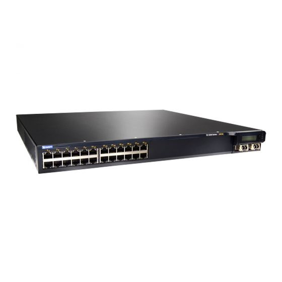
Figure 2: EX4200 Switch with 24 Gigabit Ethernet Ports Copyright © 2017, Juniper Networks, Inc.
  • Page 34: Rear Panel Of An Ex4200 Switch

    The 320 W AC power supply and the 190 W DC are flush with the chassis. The 600 W AC power supply and 930 W AC power Copyright © 2017, Juniper Networks, Inc.
  • Page 35: Lcd Panel In Ex4200 Switches

    There are two navigation buttons— Menu Enter —to the right of the LCD panel. Figure 5 on page Figure 5: LCD Panel Copyright © 2017, Juniper Networks, Inc.
  • Page 36: Lcd Panel Modes

    The number of alarms is updated every second. In the status mode, the second line displays: Virtual Chassis port (VCP) status (for an EX4200 switch that is a member of a Virtual Chassis) Status of the power supply Copyright © 2017, Juniper Networks, Inc.
  • Page 37: Lcd Panel Menus

    See Network Port LEDs in EX3200 Switches or “Network Port LEDs in EX4200 Switches” on page 24 information about the Status LED modes. Press to exit the Idle menu and go to the Status menu. Menu Copyright © 2017, Juniper Networks, Inc.
  • Page 38 It is not available for an EX3200 switch. If you do not want users to use Status menu options, disable the entire menu or individual menu options. See “Configuring the LCD Panel on EX Series Switches (CLI Procedure)” on page 173. Copyright © 2017, Juniper Networks, Inc.
  • Page 39 “Configuring the LCD Panel on EX Series Switches (CLI Procedure)” on page 173. Related Front Panel of an EX4200 Switch on page 11 Documentation Field-Replaceable Units in EX4200 Switches on page 10 Connecting and Configuring an EX Series Switch (CLI Procedure) on page 165 Copyright © 2017, Juniper Networks, Inc.
  • Page 40: Uplink Modules In Ex4200 Switches

    Likewise, you can install an XFP uplink module at one end of the connection and install an SFP+ uplink module configured to operate in the 10-gigabit mode at the other end. Copyright © 2017, Juniper Networks, Inc.
  • Page 41: Sfp Uplink Module

    If the operating mode and the configured mode for the uplink module are different, it is shown in the output of show chassis pic fpc-slot slot number pic-slot 1 Figure 7 on page 20 shows the SFP+ uplink module and the SFP+ MACsec uplink module. Copyright © 2017, Juniper Networks, Inc.
  • Page 42: Figure 7: Sfp+ And Sfp+ Macsec Uplink Module

    The SFP+ uplink module requires Junos OS for EX Series switches, Release 9.4 or later. The SFP+ MACsec uplink module requires Junos OS for EX Series switches, Release 13.2X50-D10 or later. Copyright © 2017, Juniper Networks, Inc.
  • Page 43: Xfp Uplink Module

    Chassis Status LEDs in EX4200 Switches The front panel of an EX4200 switch has three LEDs on the far right side of the panel, next to the LCD panel (see Figure 9 on page 22). Copyright © 2017, Juniper Networks, Inc.
  • Page 44: Figure 9: Chassis Status Leds In An Ex4200 Switch

    SYS (System) Green On steadily—Junos OS for EX Series switches has been loaded on the switch. Blinking—The switch is booting. Off—The switch is powered off or is halted. Copyright © 2017, Juniper Networks, Inc.
  • Page 45: Management Port Leds In Ex4200 Switches

    The management port on EX4200 switches has two LEDs that indicate link/activity and port status (see Figure 10 on page 24). The management port is set to full-duplex and the speed is set to 100 Mbps. Copyright © 2017, Juniper Networks, Inc.
  • Page 46: Network Port Leds In Ex4200 Switches

    LEDs on the network ports on the front panel. Figure 12 on page 25 shows the location of the LEDs on the uplink module ports on the SFP uplink module. Copyright © 2017, Juniper Networks, Inc.
  • Page 47: Figure 11: Leds On The Network Ports On The Front Panel

    LEDs on the uplink module ports on the XFP uplink module. Figure 11: LEDs on the Network Ports on the Front Panel Figure 12: LEDs on the Uplink Module Ports on the SFP Uplink Module Copyright © 2017, Juniper Networks, Inc.
  • Page 48: Figure 13: Leds On The Uplink Module Ports On The Sfp+ And Sfp+ Macsec Uplink

    State and Description Link/Activity Green Blinking—The port and the link are active, and there is link activity. On steadily—The port and the link are active, but there is no link activity. Off—The port is not active. Copyright © 2017, Juniper Networks, Inc.
  • Page 49 Table 11 on page 28 describes the Status LED. From the Idle menu of the LCD, use the button on the LCD panel to toggle between the ADM, DPX, POE, and SPD indicators. Enter Copyright © 2017, Juniper Networks, Inc.
  • Page 50: Table 11: Status Led On Network Ports

    The speed indicators for network ports on the front panel are: One blink per second—10 Mbps Two blinks per second—100 Mbps Three blinks per second—1000 Mbps The speed indicators for network ports on the SFP uplink module are: Green—1000 Mbps Unlit—10/100 Mbps Copyright © 2017, Juniper Networks, Inc.
  • Page 51 XFP transceivers, therefore, this LED is always green on an XFP uplink module.. Related Front Panel of an EX4200 Switch on page 11 Documentation Uplink Modules in EX4200 Switches on page 18 LCD Panel in EX4200 Switches on page 13 Copyright © 2017, Juniper Networks, Inc.
  • Page 52 EX4200 Switch Hardware Guide Copyright © 2017, Juniper Networks, Inc.
  • Page 53: Cooling System And Airflow

    Figure 15: Fan Tray Used in an EX4200 Switch Airflow Direction in the EX4200 Switch Chassis The fan tray located at the rear of the chassis provides side-to-rear chassis cooling (see Figure 16 on page 32). Copyright © 2017, Juniper Networks, Inc.
  • Page 54: Figure 16: Airflow Through The Ex4200 Switch Chassis

    Rear Panel of an EX4200 Switch on page 12 Prevention of Electrostatic Discharge Damage on page 273 Installing a Fan Tray in an EX4200 Switch on page 179 Removing a Fan Tray from an EX4200 Switch on page 180 Copyright © 2017, Juniper Networks, Inc.
  • Page 55: Power Supplies

    LEDs on the power supply, command output, show chassis and messages on the LCD panel—to indicate that the power supply is functioning normally. Ignore error indicators that might appear during the first 60 seconds. Copyright © 2017, Juniper Networks, Inc.
  • Page 56: Ac Power Supplies

    2.25 in. The power cord retainer clips extend out of the power supply by 3 in. The number of ports on which PoE is enabled determines the minimum power requirements of different switch models. Figure 17: 320 W AC Power Supply Copyright © 2017, Juniper Networks, Inc.
  • Page 57: Dc Power Supplies

    The A+ and B+ terminals are referred to as +RTN and A– and B– terminals are referred to as –48 V in “DC Power Wiring Sequence Warning” on page 281 “DC Power Electrical Safety Guidelines for Switches” on page 276. Copyright © 2017, Juniper Networks, Inc.
  • Page 58: Poe Power Budget And Ac Power Supplies

    PoE power budgets for EX4200 switch models that support PoE. Starting with Junos OS Release 11.1, EX4200 switches support enhanced PoE, a Juniper Networks extension to the IEEE 302.3af PoE standard. Enhanced PoE permits up to 18.6 W per PoE port.
  • Page 59: Ac Power Supply Leds In Ex4200 Switches

    Off—Disconnected from power or power is not coming into the power supply. On—Power is coming into the power supply. DC OK Off—Power supply is not sending out power correctly. On—Power supply is sending out power correctly. Copyright © 2017, Juniper Networks, Inc.
  • Page 60: Dc Power Supply Leds In Ex4200 Switches

    Flash Red LED A There is no input; there is no output. LED B Related Power Supply in EX4200 Switches on page 33 Documentation Connecting DC Power to an EX4200 Switch on page 152 Copyright © 2017, Juniper Networks, Inc.
  • Page 61: Viewing System Information

    NOTE: This topic applies only to the J-Web Application package. When you log in to the J-Web user interface, the dashboard for the Juniper Networks EX Series Ethernet Switches appears. Use the dashboard to view system information. The Update Available window appears if there is a latest update of the J-Web Application package available on the Juniper Networks server.
  • Page 62: Graphical Chassis Viewer

    Virtual Chassis. If the member switch does not appear dimmed, it means the switch is present and is active. Table 16 on page 41 describes the possible status of a member switch. Copyright © 2017, Juniper Networks, Inc.
  • Page 63: System Information Panel

    NOTE: In a Virtual Chassis setup for an EX6210, EX8208, or EX8216 switch, the Device model field displays details of the master Routing Engine. To view details of a member, select it. Copyright © 2017, Juniper Networks, Inc.
  • Page 64 Virtual Chassis, the value displayed in Inventory details field is always 1 FPC. FPC is a legacy term for a slot in a large Juniper Networks chassis; which simply refers to the standalone switch. For EX2200 and EX2200-C switches configured as a Virtual Chassis, the value displayed in the Inventory details field is 1–4 FPC, with the number corresponding to the number of...
  • Page 65: Health Status Panel

    Indicates the average CPU usage over 15 minutes. In a Virtual Chassis configuration, on loading the master or backup switch, the CPU load for that switch's Routing Engine is displayed by default. To display the CPU load for a specific switch's Routing Engine, click the image of that switch. Copyright © 2017, Juniper Networks, Inc.
  • Page 66 Routing Engine. CPU load Indicates the average CPU usage over 15 minutes. Flash Indicates the usage and capacity of internal flash memory and any external USB flash drive. EX8216 Switches Copyright © 2017, Juniper Networks, Inc.
  • Page 67: Capacity Utilization Panel

    Alarms Panel Displays information about the last five alarms raised in the system. For example, if there are 5 major alarms, then details of all 5 major alarms are displayed. If there are 4 major Copyright © 2017, Juniper Networks, Inc.
  • Page 68: File System Usage

    In the image, the following colors denote the interface status: Green—Interface is up and operational. Yellow—Interface is up but is nonoperational. Gray—Interface is down and nonoperational. Mouse over the interface (port) to view more information. Rear View Copyright © 2017, Juniper Networks, Inc.
  • Page 69: Table 21: Chassis Viewer For Ex2200-C Switches

    USB port Indicates the USB port for the switch. NOTE: We recommend that you use USB flash drives purchased from Juniper Networks for your EX Series switch. Fan tray Mouse over the fan tray icon to display name, status, and description information.
  • Page 70 USB port Indicates the USB port for the switch. NOTE: We recommend that you use USB flash drives purchased from Juniper Networks for your EX Series switch. Fan tray Mouse over the fan tray icon to display name, status, and description information.
  • Page 71: Table 23: Chassis Viewer For Ex4300 Switches

    Description USB port Indicates the USB port for the switch. NOTE: We recommend that you use USB flash drives purchased from Juniper Networks for your EX Series switch. Management ( ) port The management port is used to connect the switch to a management device for out-of-band management.
  • Page 72: Table 24: Chassis Viewer For Ex4500 Switches

    USB port Indicates the USB port for the switch. NOTE: We recommend that you use USB flash drives purchased from Juniper Networks for your EX Series switch. Fan tray Mouse over the fan tray icons to display name, status, and description information.
  • Page 73: Table 25: Chassis Viewer For Ex4550 Switches

    Use this port for initial switch configuration. USB port Indicates the USB port for the switch. NOTE: We recommend that you use USB flash drives purchased from Juniper Networks for your EX Series switch. Rear View of the EX4500 Switch Fan tray Mouse over the fan tray icon to display status of the fans and airflow direction information.
  • Page 74 (uplink or Virtual Chassis). USB port Indicates the USB port for the switch. NOTE: We recommend that you use USB flash drives purchased from Juniper Networks for your EX Series switch. Rear View of the EX4550 Switch Fan tray Mouse over the fan tray icon to display the status of the fans and airflow direction information.
  • Page 75: Table 26: Chassis Viewer For Ex4600 Switches

    USB port Indicates the USB port for the switch. NOTE: We recommend that you use USB flash drives purchased from Juniper Networks for your EX Series switch. Fan tray Mouse over the fan tray icons to display name, status, and description information.
  • Page 76: Table 28: Chassis Viewer For Ex8208 Switches

    You can view status for the following ports on the SRE module: USB port—Indicates the USB port for the switch. NOTE: We recommend that you use USB flash drives purchased from Juniper Networks for your EX Series switch. Management ( ) port—The management port is used to connect the switch to a management...
  • Page 77 You can view status for the following ports on the SRE module: USB port—Indicates the USB port for the switch. NOTE: We recommend that you use USB flash drives purchased from Juniper Networks for your EX Series switch. Auxiliary port—This port is unavailable.
  • Page 78: Table 29: Chassis Viewer For Ex8216 Switches

    You can view status for the following ports on the RE module: USB port—Indicates the USB port for the switch. NOTE: We recommend that you use USB flash drives purchased from Juniper Networks for your EX Series switch. Auxiliary port—This port is unavailable.
  • Page 79 USB port Indicates the USB port for the switch. NOTE: We recommend that you use USB flash drives purchased from Juniper Networks for your EX Series switch. PIC1 slot You can install a Virtual Chassis module in the PIC1 slot. Mouse over the Virtual Chassis ports to display the port status details.
  • Page 80 EX4300 Switches Hardware Overview EX4500 Switches Hardware Overview EX6210 Switch Hardware Overview EX8208 Switch Hardware Overview EX8216 Switch Hardware Overview Checking Active Alarms with the J-Web Interface on page 231 XRE200 External Routing Engine Hardware Guide Copyright © 2017, Juniper Networks, Inc.
  • Page 81: Site Planning, Preparation, And Specifications

    Site Planning, Preparation, and Specifications Preparation Overview on page 61 Power Specifications and Requirements on page 73 Transceiver and Cable Specifications on page 79 Pinout Specifications on page 91 Planning the Virtual Chassis on page 111 Copyright © 2017, Juniper Networks, Inc.
  • Page 82 EX4200 Switch Hardware Guide Copyright © 2017, Juniper Networks, Inc.
  • Page 83: Preparation Overview

    Power Measure distance between external power sources and switch installation site. Locate sites for connection of system grounding. Calculate the power consumption and “Power Specifications for EX4200 requirements. Switches” on page 73 Hardware Configuration Copyright © 2017, Juniper Networks, Inc.
  • Page 84: Environmental Requirements And Specifications For Ex Series Switches

    Mounting an EX4200 Switch on page 128 Environmental Requirements and Specifications for EX Series Switches The switch must be installed in a rack or cabinet housed in a dry, clean, well-ventilated, and temperature-controlled environment. Copyright © 2017, Juniper Networks, Inc.
  • Page 85: Table 32: Ex Series Switch Environmental Tolerances

    Complies with Zone 4 degradation up to the relative humidity range temperature range 32° F (0° C) earthquake 10,000 feet 10% through 85% through 113° F (45° C) requirements as per (3048 meters) (noncondensing) GR-63, Issue 4. Copyright © 2017, Juniper Networks, Inc.
  • Page 86 158° F (70° C) humidity range 5% through 93%, noncondensing NOTE: As defined in NEBS GR-63-CORE, Issue 4, short-term events can be up to 96 hours in duration but not more than 15 days per year. Copyright © 2017, Juniper Networks, Inc.
  • Page 87 Complies with Zone 4 degradation up to the relative humidity range temperature range 41° F (5° C) earthquake 10,000 feet 10% through 85% through 104° F (40° C) requirements as per (3048 meters) (noncondensing) GR-63, Issue 4. Copyright © 2017, Juniper Networks, Inc.
  • Page 88: General Site Guidelines

    Keep the area around the chassis free from dust and conductive material, such as metal flakes. Follow prescribed airflow guidelines to ensure that the cooling system functions properly and that exhaust from other equipment does not blow into the intake vents of the device. Copyright © 2017, Juniper Networks, Inc.
  • Page 89: Site Electrical Wiring Guidelines

    Electrical hazards as a result of power surges conducted over the lines into the equipment Related General Safety Guidelines and Warnings on page 243 Documentation General Electrical Safety Guidelines and Warnings on page 271 Prevention of Electrostatic Discharge Damage on page 273 Copyright © 2017, Juniper Networks, Inc.
  • Page 90: Rack Requirements

    Secure the rack to the ceiling brackets as well as wall or floor brackets for maximum stability. Related Rack-Mounting and Cabinet-Mounting Warnings on page 254 Documentation Cabinet Requirements You can mount the device in a cabinet that contains a 19-in. rack. Cabinet requirements consist of: Cabinet size Copyright © 2017, Juniper Networks, Inc.
  • Page 91: Requirements For Mounting An Ex4200 Switch On A Desktop Or Wall

    Insert the screws into wall studs wherever possible to provide added support for the chassis. Copyright © 2017, Juniper Networks, Inc.
  • Page 92: Figure 20: Clearance Requirements For Airflow And Hardware Maintenance For

    EX4200 Switch Hardware Guide Use the wall-mount kit from Juniper Networks to mount the switch on a wall. The wall-mount kit is not part of the standard package and must be ordered separately. Related Clearance Requirements for Airflow and Hardware Maintenance for EX4200 Switches...
  • Page 93: Figure 21: Airflow Through The Ex4200 Switch Chassis

    Rack Requirements on page 68 Documentation Cabinet Requirements on page 68 General Site Guidelines on page 66 Rack-Mounting and Cabinet-Mounting Warnings on page 254 Cooling System and Airflow in an EX4200 Switch on page 31 Copyright © 2017, Juniper Networks, Inc.
  • Page 94 EX4200 Switch Hardware Guide Copyright © 2017, Juniper Networks, Inc.
  • Page 95: Switches

    7 A (for switches with 24 ports equipped for PoE) 12 A (for switches with 48 ports equipped for PoE) Table 37: DC Power Supply Electrical Specifications Item Specification DC input voltage 36 through 72 VDC Copyright © 2017, Juniper Networks, Inc.
  • Page 96: Ac Power Cord Specifications For Ex4200 Switches

    (approximately 14.75 feet) in length, to comply with National Electrical Code (NEC) Sections 400-8 (NFPA 75, 5-2.2) and 210-52 and Canadian Electrical Code (CEC) Section 4-010(3). The cords supplied with the switch are in compliance. Copyright © 2017, Juniper Networks, Inc.
  • Page 97: Figure 22: Ac Plug Types

    Table 38 on page Figure 22: AC Plug Types Related Power Supply in EX4200 Switches on page 33 Documentation Copyright © 2017, Juniper Networks, Inc.
  • Page 98: Calculating The Ex Series Switch Fiber-Optic Cable Power Budget

    The power margin (P ) is the amount of power available after attenuation or link loss (LL) has been subtracted from the power budget (P Copyright © 2017, Juniper Networks, Inc.
  • Page 99: Power Specifications And Requirements

    (2 km) * (0.5 dBm/km) = 1 dBm Clock Recovery Module (CRM) 1 dBm 1 dBm NOTE: For information about the actual amount of signal loss caused by equipment and other factors, see your vendor documentation for that equipment. Copyright © 2017, Juniper Networks, Inc.
  • Page 100 Calculating the EX Series Switch Fiber-Optic Cable Power Budget on page 76 Documentation Understanding EX Series Switches Fiber-Optic Cable Signal Loss, Attenuation, and Dispersion on page 88 Pluggable Transceivers Supported on EX Series Switches on page 80 Copyright © 2017, Juniper Networks, Inc.
  • Page 101: Transceiver And Cable Specifications

    (JTAC) can help you diagnose the source of the problem. Your JTAC engineer might recommend that you check the third-party optic or cable and potentially replace it with an equivalent Juniper Networks optic or cable that is qualified for the device.
  • Page 102: Pluggable Transceivers Supported On Ex Series Switches

    6 seconds for the interface to display the operational commands. Use only optical transceivers and optical connectors purchased from Juniper Networks for your EX Series switches. For the list and specifications of transceivers supported on EX2200 switches, see Pluggable Transceivers Supported on EX2200 Switches.
  • Page 103: Sfp+ Direct Attach Copper Cables For Ex Series Switches

    3 ft (1 m), 10 ft (3 m), and 16 ft (5 m) EX3200 switches Junos OS Release 10.3 3 ft (1 m), 10 ft (3 m), 16 ft (5 m), and 23 ft (7 m) Copyright © 2017, Juniper Networks, Inc.
  • Page 104 3 ft (1 m), 10 ft (3 m), 16 ft (5 m), and 23 ft (7 m) EX4500 switches Junos OS Release 10.2 3 ft (1 m), 10 ft (3 m), and 23 ft (7 m) Junos OS Release 11.2 16 ft (5 m) Copyright © 2017, Juniper Networks, Inc.
  • Page 105 (JTAC) can help you diagnose the source of the problem. Your JTAC engineer might recommend that you check the third-party optic or cable and potentially replace it with an equivalent Juniper Networks optic or cable that is qualified for the device.
  • Page 106: Table 41: Sfp+ Direct Attach Copper Cable Specifications

    30 AWG Minimum cable bend radius 1 in. (2.54 cm) Cable characteristic impedance 100 ohms Crosstalk between pairs 2% maximum Time delay 1.31 nsec/ft Length 3.3 ft (1 m) Support for Virtual Chassis configuration Copyright © 2017, Juniper Networks, Inc.
  • Page 107 30 AWG Minimum cable bend radius 1 in. (2.54 cm) Cable characteristic impedance 100 ohms Crosstalk between pairs 2% maximum Time delay 1.31 nsec/ft Length 9.9 ft (3 m) Support for Virtual Chassis configuration Copyright © 2017, Juniper Networks, Inc.
  • Page 108 24 AWG Minimum cable bend radius 1 in. (2.54 cm) Cable characteristic impedance 100 ohms Crosstalk between pairs 2% maximum Time delay 1.31 nsec/ft Length 16.4 ft (5 m) Support for Virtual Chassis configuration Copyright © 2017, Juniper Networks, Inc.
  • Page 109: Standards Supported By These Cables

    Removing a Transceiver on page 195 Management Cable Specifications Table 42 on page 88 lists the specifications for the cables that connect the console ( and management ( ) ports to management devices. MGMT Copyright © 2017, Juniper Networks, Inc.
  • Page 110: Understanding Ex Series Switches Fiber-Optic Cable Signal Loss, Attenuation

    For information about the maximum transmission distance and supported wavelength range for the types of single-mode and multimode fiber-optic cables that are used on different EX Series switches see “Pluggable Transceivers Supported on EX Series Switches” on page Copyright © 2017, Juniper Networks, Inc.
  • Page 111: Attenuation And Dispersion In Fiber-Optic Cable

    (including those from dispersion), and a safety margin for unexpected losses. Related Calculating the EX Series Switch Fiber-Optic Cable Power Budget on page 76 Documentation Calculating the EX Series Switch Fiber-Optic Cable Power Margin on page 76 Copyright © 2017, Juniper Networks, Inc.
  • Page 112 EX4200 Switch Hardware Guide Copyright © 2017, Juniper Networks, Inc.
  • Page 113: Pinout Specifications

    Virtual Chassis Ports Connector Pinout Information for EX4200 Switches on page 107 Console Port Connector Pinout Information The console port on a Juniper Networks device is an RS-232 serial interface that uses an RJ-45 connector to connect to a console management device. The default baud rate for the console port is 9600 baud.
  • Page 114: Usb Port Specifications For An Ex Series Switch

    Documentation Configuring the Console Port Type (CLI Procedure) USB Port Specifications for an EX Series Switch The following Juniper Networks USB flash drives have been tested and are officially supported for the USB port on all EX Series switches: RE-USB-1G-S...
  • Page 115: Rj-45 Management Port Connector Pinout Information

    Booting an EX Series Switch Using a Software Package Stored on a USB Flash Drive RJ-45 Management Port Connector Pinout Information Table 44 on page 93 provides the pinout information for the RJ-45 connector for the management port on Juniper Networks devices. Table 44: RJ-45 Management Port Connector Pinout Information Signal Description...
  • Page 116: Port, Qsfp+ Port, Sfp+ Port, And Sfp Port Connector Pinout Information

    Transmit/receive data pair 4 TRP4- Transmit/receive data pair 4 Table 46: SFP Network Port Connector Pinout Information Signal Description VeeT Module transmitter ground TX_Fault Module transmitter fault TX_Disable Transmitter disabled 2-wire serial interface data line Copyright © 2017, Juniper Networks, Inc.
  • Page 117: Table 47: Sfp+ Network Port Connector Pinout Information

    Table 47: SFP+ Network Port Connector Pinout Information Signal Description VeeT Module transmitter ground TX_Fault Module transmitter fault TX_Disable Transmitter disabled 2-wire serial interface data line SCL- 2-wire serial interface clock MOD_ABS Module absent Copyright © 2017, Juniper Networks, Inc.
  • Page 118: Table 48: Qsfp+ Network Port Connector Pinout Information

    Module transmitter 3.3 V supply VeeT Module transmitter ground Transmitter noninverted data input Transmitter inverted data input VeeT Module transmitter ground Table 48: QSFP+ Network Port Connector Pinout Information Signal TX2n TX2p TX4n TX4p ModSelL Copyright © 2017, Juniper Networks, Inc.
  • Page 119 Chapter 9: Pinout Specifications Table 48: QSFP+ Network Port Connector Pinout Information (continued) Signal LPMode_Reset VccRx RX3p RX3n RX1p RX1n RX2n RX2p RX4n RX4p ModPrsL IntL VccTx Vcc1 Reserved Copyright © 2017, Juniper Networks, Inc.
  • Page 120: Rj-45 To Db-9 Serial Port Adapter Pinout Information

    Table 49 on page 98 provides the pinout information for the RJ-45 to DB-9 serial port adapter. Table 49: RJ-45 to DB-9 Serial Port Adapter Pinout Information RJ-45 Pin Signal DB-9 Pin Signal Copyright © 2017, Juniper Networks, Inc.
  • Page 121: Uplink Modules Connector Pinout Information For Ex4200 Switches

    You can use these ports to connect an access switch to a distribution switch. You can also use optional uplink module ports to connect members of a Virtual Chassis across multiple wiring closets. Table 50: Uplink Modules Connector Pinout Information Pin Number Pin Name Uplink_I2C_SCK Uplink_PD Copyright © 2017, Juniper Networks, Inc.
  • Page 122 EX4200 Switch Hardware Guide Table 50: Uplink Modules Connector Pinout Information (continued) Pin Number Pin Name POWER (12V) XAUI0_RX0N XAUI0_RX2N Uplink_P25_LED2 XAUI1_RX0N Uplink_P27_LED2 XAUI1_RX2N SRX28N Uplink_XAUI_XMDIO SRX26N SGMIIRXN Uplink_I2C_Rst Uplink_Intr Uplink_Pwr_En Uplink_P26_LED0 POWER (12V) POWER (12V) Copyright © 2017, Juniper Networks, Inc.
  • Page 123 Chapter 9: Pinout Specifications Table 50: Uplink Modules Connector Pinout Information (continued) Pin Number Pin Name XAUI0_RX0P XAUI0_RX2P XAUI1_RX0P XAUI1_RX2P SRX28P SRX26P SGMIIRXP CPU_UPLINK_MDC Uplink_I2C_SDA CPU_UPLINK_MDIO Uplink_P26_LED1 UPLNK_PWR_OK POWER (12V) XAUI0_TX1N XAUI0_TX3N Copyright © 2017, Juniper Networks, Inc.
  • Page 124 EX4200 Switch Hardware Guide Table 50: Uplink Modules Connector Pinout Information (continued) Pin Number Pin Name XAUI1_TX1N XAUI1_TX3N STX27N STX25N Uplink_Rst Uplink_Status_LED0 POWER (12V) XAUI0_TX0N XAUI0_TX1P XAUI0_TX2N XAUI0_TX3P XAUI1_TX0N XAUI1_TX1P XAUI1_TX2N XAUI1_TX3P Copyright © 2017, Juniper Networks, Inc.
  • Page 125 Chapter 9: Pinout Specifications Table 50: Uplink Modules Connector Pinout Information (continued) Pin Number Pin Name STX28N STX27P STX26N STX25P SGMIITXN Uplink_Hotswap_LED Uplink_Spare_Intr Uplink_Status_LED1 Uplink_P27_LED0 POWER (12V) POWER (12V) XAUI0_TX0P XAUI0_TX2P XAUI1_TX0P XAUI_TX2P STX28P STX26P Copyright © 2017, Juniper Networks, Inc.
  • Page 126 EX4200 Switch Hardware Guide Table 50: Uplink Modules Connector Pinout Information (continued) Pin Number Pin Name SGMIITXP Uplink_Expander_Intr Uplink_P27_LED1 POWER (12V) XAUI0_RX1N XAUI0_RX3N XAUI1_RX1N XAUI1_RX3N SRX27N SRX25N Uplink_P25_LED0 Copyright © 2017, Juniper Networks, Inc.
  • Page 127 Chapter 9: Pinout Specifications Table 50: Uplink Modules Connector Pinout Information (continued) Pin Number Pin Name POWER (12V) Uplink_PD_Loopback XAUI0_RX1P XAUI0_RX3P Uplink_P26_ LED2 XAUI1_RX1P Uplink_P28_ LED2 XAUI1_RX3P SRX27P Uplink_XAUI_MDC SRX25P Serial_RX Uplink_P25_LED1 Uplink_P28_LED0 POWER (12V) POWER (12V) Copyright © 2017, Juniper Networks, Inc.
  • Page 128 Uplink Modules in EX4200 Switches on page 18 Documentation Front Panel of an EX4200 Switch on page 11 Installing an Uplink Module in an EX4200 Switch on page 187 Removing an Uplink Module from an EX4200 Switch on page 189 Copyright © 2017, Juniper Networks, Inc.
  • Page 129: Virtual Chassis Ports Connector Pinout Information For Ex4200 Switches

    Table 51 on page 107 provides the Virtual Chassis ports (VCPs) connector pinout information. Table 51: Virtual Chassis Ports (VCPs) Connector Pinout Information Pin Number Pin Name P1TXP0 P1TXN0 P1TXP1 P1TXN1 P1TXP2 P1TXN2 P1TXP3 P1TXN3 Copyright © 2017, Juniper Networks, Inc.
  • Page 130 EX4200 Switch Hardware Guide Table 51: Virtual Chassis Ports (VCPs) Connector Pinout Information (continued) Pin Number Pin Name P2TXP0 P2TXN0 P2TXP1 P2TXN1 P2TXP2 P2TXN2 P2TXP3 P2TXN3 P1RXP0 P1RXN0 P1RXP1 P1RXN1 P1RXP2 P1RXN2 Copyright © 2017, Juniper Networks, Inc.
  • Page 131 Chapter 9: Pinout Specifications Table 51: Virtual Chassis Ports (VCPs) Connector Pinout Information (continued) Pin Number Pin Name P1RXP3 P1RXN3 P2RXP0 P2RXN0 P2RXP1 P2RXN1 P2RXP2 P2RXN2 P2RXP3 P2RXN3 Copyright © 2017, Juniper Networks, Inc.
  • Page 132 Planning EX4200, EX4500, and EX4550 Virtual Chassis on page 114 Understanding EX Series Virtual Chassis Components Understanding EX4200, EX4500, and EX4550 Virtual Chassis Hardware Configurations on page 111 Connecting a Virtual Chassis Cable to an EX4200 Switch on page 213 Copyright © 2017, Juniper Networks, Inc.
  • Page 133: Planning The Virtual Chassis

    SFP, SFP+, or XFP uplink module ports configured as VCPs SFP network ports on EX4200-24F switches configured as VCPs On EX4500 switches: The dedicated VCPs on the Virtual Chassis module SFP+ network ports configured as VCPs Copyright © 2017, Juniper Networks, Inc.
  • Page 134: Number Of Switches, Required Software Releases, And Member Roles That You Configure In The Virtual Chassis

    The number of switches that you can configure in a Virtual Chassis and the role that can be assigned to each switch in a Virtual Chassis depend on the Juniper Networks Junos operating system (Junos OS) release that is running on the switches.
  • Page 135: Virtual Chassis Module

    Release 11.4R1, you must install a Virtual Chassis module for using the switch in a Virtual Chassis configuration. Starting with Release 11.4R1, you can use uplink port connections to interconnect EX4500 member switches into a Virtual Chassis. Copyright © 2017, Juniper Networks, Inc.
  • Page 136: Switch Role And Member Id On The Lcd Panel

    You can interconnect up to ten EX4500 switches into a Virtual Chassis composed exclusively of EX4500 switches. EX4550 switches only Junos OS Release 12.2 or later You can interconnect up to ten EX4550 switches into a Virtual Chassis composed exclusively of EX4550 switches. Copyright © 2017, Juniper Networks, Inc.
  • Page 137: Table 57: Cabling Requirements For A Virtual Chassis

    0.5 m through 5 m 1 m, 3 m, and 5 m You must order these cables separately for EX4200, EX4500, and EX4550 switches, including EX4500 switches that are shipped with a preinstalled Virtual Chassis module. Copyright © 2017, Juniper Networks, Inc.
  • Page 138: Virtual Chassis Cabling Configuration Examples For Ex4200 Switches

    VCP cables, you can install the XFP uplink module, the SFP uplink module, or the SFP+ uplink module and set the uplink module ports as VCP interfaces. See Setting an Uplink Port on an EX Series Switch as a Virtual Chassis Port (CLI Procedure). Copyright © 2017, Juniper Networks, Inc.
  • Page 139: Figure 24: Ex4200 Switches Mounted On A Single Rack And Connected In A Ring

    Figure 24: EX4200 Switches Mounted on a Single Rack and Connected in a Ring Topology Using Short and Long Cables: Option 1 Figure 25: EX4200 Switches Mounted on a Single Rack and Connected in a Ring Topology Using Short and Long Cables: Option 2 Copyright © 2017, Juniper Networks, Inc.
  • Page 140: Figure 26: Ex4200 Switches Mounted On A Single Rack And Connected In A Ring Topology Using Short And Medium Cables

    Understanding EX Series Virtual Chassis Components Planning EX4200, EX4500, and EX4550 Virtual Chassis on page 114 Virtual Chassis Ports Connector Pinout Information for EX4200 Switches on page 107 Example: Configuring an EX4200 Virtual Chassis Interconnected Across Multiple Wiring Closets Copyright © 2017, Juniper Networks, Inc.
  • Page 141: Initial Installation And Configuration

    Unpacking the Switch on page 121 Installing the Switch on page 127 Connecting the Switch to Power on page 143 Connecting the Switch to the Network on page 157 Performing Initial Configuration on page 161 Copyright © 2017, Juniper Networks, Inc.
  • Page 142 EX4200 Switch Hardware Guide Copyright © 2017, Juniper Networks, Inc.
  • Page 143: Unpacking The Switch

    An inventory of parts provided with the switch is provided in “Parts Inventory (Packing List) for an EX4200 Switch” on page 122. Save the shipping carton and packing materials in case you need to move or ship the switch later. Copyright © 2017, Juniper Networks, Inc.
  • Page 144: Parts Inventory (Packing List) For An Ex4200 Switch

    If any part on the packing list is missing, contact your customer service representative or contact Juniper customer care from within the U.S. or Canada by telephone at 1-888-314-5822. For international-dial or direct-dial options in countries without toll-free numbers, see http://www.juniper.net/support/requesting-support.html...
  • Page 145: Table 58: Packing List For An Ex4200 Switch

    Power cord retainer clip for these models is not shipped switches by default; you must order it separately. Mounting brackets Mounting screws to attach the mounting brackets to the switch chassis Rubber feet RJ-45 cable and RJ-45 to DB-9 serial port adapter Copyright © 2017, Juniper Networks, Inc.
  • Page 146: Registering Products-Mandatory For Validating Slas

    Documentation EX4200 Switches Hardware Overview on page 3 Registering Products—Mandatory for Validating SLAs Register all new Juniper Networks hardware products and changes to an existing installed product using the Juniper Networks website to activate your hardware replacement service-level agreements (SLAs).
  • Page 147 Chapter 11: Unpacking the Switch Contacting Customer Support to Obtain a Return Materials Authorization for an NFX250 Device Copyright © 2017, Juniper Networks, Inc.
  • Page 148 EX4200 Switch Hardware Guide Copyright © 2017, Juniper Networks, Inc.
  • Page 149: Installing The Switch

    “Mounting an EX4200 Switch in a Recessed Position in a Rack or Cabinet” on page 137 (using the 2-in.-recess front brackets from the separately orderable four-post rack-mount kit) Copyright © 2017, Juniper Networks, Inc.
  • Page 150: Mounting An Ex4200 Switch

    On a desk or other level surface by using rubber feet. The switch is shipped with four rubber feet to be used to stabilize the chassis on a desk or other level surface. On a wall by using the separately orderable wall-mount kit. Copyright © 2017, Juniper Networks, Inc.
  • Page 151: Mounting An Ex4200 Switch On A Desk Or Other Level Surface

    Turn the chassis upside down on the desk or the level surface where you intend to mount the switch. Attach the rubber feet to the bottom of the chassis, as shown in Figure 30 on page 130. Copyright © 2017, Juniper Networks, Inc.
  • Page 152: Mounting An Ex4200 Switch On Two Posts In A Rack Or Cabinet

    If you need to mount the switch in a recessed position on either a two-post rack or a four-post rack, you can use the 2-in.-recess front brackets provided in the separately orderable four-post rack-mount kit. Before mounting the switch on two posts in a rack: Copyright © 2017, Juniper Networks, Inc.
  • Page 153 For example, if you want to front-mount the switch, align the brackets along the front of the side panel. Figure 31 on page 132. Copyright © 2017, Juniper Networks, Inc.
  • Page 154: Figure 31: Attaching The Mounting Bracket To The Side Panel Of The Switch

    Align the bottom hole in both the mounting brackets with a hole in each rack rail, making sure the chassis is level. See Figure 32 on page 132. Figure 32: Mounting the Switch on Two Posts in a Rack Mounting rack Mounting bracket Copyright © 2017, Juniper Networks, Inc.
  • Page 155: Mounting An Ex4200 Switch On Four Posts In A Rack Or Cabinet

    2 in. recessed from the rack front, thus ensuring that the protective earthing terminal is accessible through the opening in the rear mounting-blade. Before mounting the switch on four posts in a rack: Copyright © 2017, Juniper Networks, Inc.
  • Page 156 If you are mounting multiple units on a rack, mount the heaviest unit at the bottom of the rack and mount the other units from the bottom of the rack to the top in decreasing order of the weight of the units. Copyright © 2017, Juniper Networks, Inc.
  • Page 157: Figure 33: Attaching The Front-Mounting Bracket To The Side Mounting-Rail

    Have one person grasp both sides of the switch, lift the switch, and position it in the rack, aligning the side mounting-rail holes with the threaded holes in the front post Copyright © 2017, Juniper Networks, Inc.
  • Page 158: Figure 35: Mounting The Switch To The Front Posts In A Rack

    Slide the rear mounting-blades into the side mounting-rails. See Figure 36 on page 136. Figure 36: Sliding the Rear Mounting-Blades into the Side-Mounting Rail 1— Rear mounting-blade 3— Switch 2—Side mounting-rail Copyright © 2017, Juniper Networks, Inc.
  • Page 159: Mounting An Ex4200 Switch In A Recessed Position In A Rack Or Cabinet

    “Mounting an EX4200 Switch on Two Posts in a Rack or Cabinet” on page 130. Related Connecting Earth Ground to an EX Series Switch on page 143 Documentation Rack-Mounting and Cabinet-Mounting Warnings on page 254 Copyright © 2017, Juniper Networks, Inc.
  • Page 160: Mounting An Ex4200 Switch On A Wall

    NOTE: For easier lifting, install any additional power supplies only after you mount the switch on the wall. To mount the switch on a wall: Copyright © 2017, Juniper Networks, Inc.
  • Page 161: Figure 37: Attaching Wall-Mount Brackets To The Switch Chassis

    Grasp each side of the switch or switches, lift the switch or switches, and hang the brackets from the mounting screws as shown in Figure 38 on page 140. Copyright © 2017, Juniper Networks, Inc.
  • Page 162: Installing And Removing Ex4200 Switch Hardware Components

    Power supply Fan tray Uplink module Transceivers The power supply, fan tray, uplink module, and transceivers are hot-removable and hot-insertable: You can remove and replace them without powering off the switch or disrupting switch functions. Copyright © 2017, Juniper Networks, Inc.
  • Page 163 Cooling System and Airflow in an EX4200 Switch on page 31 Documentation Power Supply in EX4200 Switches on page 33 Uplink Modules in EX4200 Switches on page 18 Pluggable Transceivers Supported on EX4200 Switches on page 79 Copyright © 2017, Juniper Networks, Inc.
  • Page 164 EX4200 Switch Hardware Guide Copyright © 2017, Juniper Networks, Inc.
  • Page 165: Connecting The Switch To Power

    Parts and Tools Required for Connecting an EX Series Switch to Earth Ground Table 59 on page 144 lists the earthing terminal location, grounding cable requirements, grounding lug specifications, screws and washers required, and the screwdriver needed Copyright © 2017, Juniper Networks, Inc.
  • Page 166: Table 59: Parts And Tools Required For Connecting An Ex Series Switch To Earth Ground

    Phillips (+) of the minimum 90°C LCC10-14BWL or screws with #10 number 2 chassis wire, or as equivalent— split-lock washer— permitted by the not provided not provided local code Two #10 flat washers—not provided Copyright © 2017, Juniper Networks, Inc.
  • Page 167: Special Instructions To Follow Before Connecting Earth Ground To A

    Two ¼-20 x 0.5 in. Phillips (+) the chassis mm²), minimum LCD2-14A-Q or screws with #¼” number 2 60°C wire, or as equivalent split-washer permitted by the —provided —provided local code Two #¼” flat washers— provided Copyright © 2017, Juniper Networks, Inc.
  • Page 168: Switch

    Special Instructions EX3200 NOTE: Some early variants of EX3200 switches for which the Juniper Networks model number on the label next to the protective earthing terminal is from 750-021xxx through 750-030xxx require 10-24x.25 in. screws. Copyright © 2017, Juniper Networks, Inc.
  • Page 169: Figure 39: Connecting The Grounding Lug To A Switch Mounted On Four Posts Of

    Special Instructions EX4200 NOTE: Some early variants of EX4200 switches for which the Juniper Networks model number on the label next to the protective earthing terminal is from 750-021xxx through 750-030xxx require 10-24x.25 in. screws. NOTE: The protective earthing terminal on an EX4200 switch mounted on four posts of a rack is accessible through the slot on the left rear bracket only if the rack is 27.5 in.
  • Page 170: Connecting Earth Ground To An Ex Series Switch

    Connecting DC Power to an EX3300 Switch Connecting AC Power to an EX3400 Switch Connecting AC Power to an EX4200 Switch on page 149 Connecting DC Power to an EX4200 Switch on page 152 Copyright © 2017, Juniper Networks, Inc.
  • Page 171: Connecting Ac Power To An Ex4200 Switch

    For installations that require a separate grounding conductor to the chassis, use the protective earthing terminal on the switch chassis to connect to the earth ground. For instructions on connecting earth ground, see “Connecting Earth Ground to Copyright © 2017, Juniper Networks, Inc.
  • Page 172 (see Figure 42 on page 151). If the AC power source outlet has a power switch, set it to the OFF (0) position. Insert the power cord plug into an AC power source outlet. Copyright © 2017, Juniper Networks, Inc.
  • Page 173: Figure 41: Connecting The Ac Power Cord Retainer Clip To An Ac Power Supply In An Ex4200 Switch

    Connecting and Configuring an EX Series Switch (J-Web Procedure) on page 168 Connecting DC Power to an EX4200 Switch on page 152 Power Supply in EX4200 Switches on page 33 AC Power Supply LEDs in EX4200 Switches on page 37 Copyright © 2017, Juniper Networks, Inc.
  • Page 174: Connecting Dc Power To An Ex4200 Switch

    “Connecting Earth Ground to an EX Series Switch” on page 143. Install the power supply in the chassis. For instructions on , see “Installing a Power Supply in an EX4200 Switch” on page 183. Copyright © 2017, Juniper Networks, Inc.
  • Page 175: Figure 44: Removing The Terminal Block Cover From A Dc Power Supply

    (see Figure 44 on page 153). Save the screw. Figure 44: Removing the Terminal Block Cover from a DC Power Supply Remove the screws on the terminals using the screwdriver. Save the screws. Copyright © 2017, Juniper Networks, Inc.
  • Page 176 Tighten the screws on the power supply terminals on both the power supplies until snug using the screwdriver. Do not overtighten—apply between 8 lb-in. (0.9 Nm) and 9 lb-in. (1.02 Nm) of torque to the screws. Copyright © 2017, Juniper Networks, Inc.
  • Page 177: Figure 45: Securing Ring Lugs To The Terminals On The Dc Power Supply

    Connecting and Configuring an EX Series Switch (CLI Procedure) on page 165 Documentation Connecting and Configuring an EX Series Switch (J-Web Procedure) on page 168 Power Supply in EX4200 Switches on page 33 DC Power Supply LEDs in EX4200 Switches on page 38 Copyright © 2017, Juniper Networks, Inc.
  • Page 178 EX4200 Switch Hardware Guide Copyright © 2017, Juniper Networks, Inc.
  • Page 179: Connecting The Switch To The Network

    Figure 47 on page 158): Connect one end of the Ethernet cable to the management port (labeled MGMT ) on the device. ETHERNET Connect the other end of the Ethernet cable to the management device. Copyright © 2017, Juniper Networks, Inc.
  • Page 180: Connector

    PC directly to the device, use a combination of the RJ-45 to DB-9 female adapter supplied with the device and a USB to DB-9 male adapter. You must provide the USB to DB-9 male adapter. Copyright © 2017, Juniper Networks, Inc.
  • Page 181: Connecting A Fiber-Optic Cable

    If the fiber-optic cable connector is covered with a rubber safety cap, remove the cap. Save the cap. Remove the rubber safety cap from the optical transceiver. Save the cap. Insert the cable connector into the optical transceiver (see Figure 51 on page 160). Copyright © 2017, Juniper Networks, Inc.
  • Page 182: Figure 51: Connecting A Fiber-Optic Cable To An Optical Transceiver Installed In

    Related Disconnecting a Fiber-Optic Cable from a Device on page 200 Documentation Installing a Transceiver on page 193 Maintaining Fiber-Optic Cables on page 201 Copyright © 2017, Juniper Networks, Inc.
  • Page 183: Performing Initial Configuration

    ). Although you can install only one uplink module, the interfaces for both are shown below. system { syslog { user * { any emergency; file messages { any notice; authorization info; file interactive-commands { Copyright © 2017, Juniper Networks, Inc.
  • Page 184 { unit 0 { family ethernet-switching; ge-0/0/5 { unit 0 { family ethernet-switching; ge-0/0/6 { unit 0 { family ethernet-switching; ge-0/0/7 { unit 0 { family ethernet-switching; ge-0/0/8 { unit 0 { family ethernet-switching; Copyright © 2017, Juniper Networks, Inc.
  • Page 185 0 { family ethernet-switching; ge-0/0/16 { unit 0 { family ethernet-switching; ge-0/0/17 { unit 0 { family ethernet-switching; ge-0/0/18 { unit 0 { family ethernet-switching; ge-0/0/19 { unit 0 { family ethernet-switching; ge-0/0/20 { Copyright © 2017, Juniper Networks, Inc.
  • Page 186 0 { family ethernet-switching; ge-0/1/1 { unit 0 { family ethernet-switching; ge-0/1/2 { unit 0 { family ethernet-switching; ge-0/1/3 { unit 0 { family ethernet-switching; protocols { igmp-snooping{ vlan all; lldp { interface all; Copyright © 2017, Juniper Networks, Inc.
  • Page 187: Connecting And Configuring An Ex Series Switch (Cli Procedure)

    , revert to the factory-default configuration. ezsetup See Reverting to the Default Factory Configuration for the EX Series Switch. Using the CLI, set the following parameter values in the console server or PC: Baud rate—9600 Flow control—None Data—8 Parity—None Copyright © 2017, Juniper Networks, Inc.
  • Page 188 Using the Mini-USB Type-B Console Port. At the Junos OS shell prompt , type ezsetup. root% Enter the hostname. This is optional. Enter the root password you want to use for the device. Reenter the root password when prompted. Copyright © 2017, Juniper Networks, Inc.
  • Page 189 If you use the J-Web interface to continue configuring the switch, the Web session is redirected to the new management IP address. If the connection cannot be made, the J-Web interface displays instructions for starting a J-Web session. Copyright © 2017, Juniper Networks, Inc.
  • Page 190: Connecting And Configuring An Ex Series Switch (J-Web Procedure)

    This topic describes the J-Web procedure. NOTE: Before you begin the configuration, enable a DHCP client on the management PC that you will connect to the switch so that the PC can obtain an IP address dynamically. Copyright © 2017, Juniper Networks, Inc.
  • Page 191 EX3200, EX3300, EX4200, EX4300, EX4500, EX4550, EX6200, or EX8200 switch—The LCD panel displays a count-down timer when the switch is in initial setup mode. Copyright © 2017, Juniper Networks, Inc.
  • Page 192: Figure 52: Lcd Panel In An Ex3200, Ex4200, Ex4500, Ex4550, Or Ex8200

    EX3300, EX4500, or EX4550 switch—Connect the cable to the port labeled MGMT on the front panel (LCD panel side) of the switch. EX4300 switch—Connect the cable to the port labeled on the rear panel of MGMT the switch. Copyright © 2017, Juniper Networks, Inc.
  • Page 193 In-band Management—Create new VLAN for management Select this option to create a management VLAN. Click . Specify the VLAN Next name, VLAN ID, member interfaces, management IP address, and default gateway for the new VLAN. Out-of-band Management—Configure management port Copyright © 2017, Juniper Networks, Inc.
  • Page 194 Installing and Connecting an EX4500 Switch Installing and Connecting an EX4550 Switch Installing and Connecting an EX4600 Switch Installing and Connecting an EX6210 Switch Installing and Connecting an EX8208 Switch Installing and Connecting an EX8216 Switch Copyright © 2017, Juniper Networks, Inc.
  • Page 195: Configuring The Lcd Panel On Ex Series Switches (Cli Procedure)

    To disable a menu: [edit] user@switch# set chassis lcd-menu menu-item menu-name disable To enable a menu: [edit] user@switch# delete chassis lcd-menu menu-item menu-name disable To disable a menu option: [edit] user@switch# set chassis lcd-menu menu-item menu-option disable Copyright © 2017, Juniper Networks, Inc.
  • Page 196: Configuring A Custom Display Message

    You can view the custom message by issuing the command. show chassis lcd Related LCD Panel in EX3200 Switches Documentation LCD Panel in EX3300 Switches LCD Panel in EX4200 Switches on page 13 LCD Panel in EX4300 Switches Copyright © 2017, Juniper Networks, Inc.
  • Page 197 Chapter 15: Performing Initial Configuration LCD Panel in EX4500 Switches LCD Panel in EX4550 Switches LCD Panel in an EX6200 Switch LCD Panel in an EX8200 Switch LCD Panel in an XRE200 External Routing Engine Copyright © 2017, Juniper Networks, Inc.
  • Page 198 EX4200 Switch Hardware Guide Copyright © 2017, Juniper Networks, Inc.
  • Page 199: Installing, Maintaining, And Replacing Components

    Maintaining and Replacing Fiber-Optic Cable on page 199 Replacing a Member Switch to Virtual Chassis on page 203 Maintaining and Replacing Virtual Chassis Cable on page 213 Contacting Customer Support and Returning the Chassis or Components on page 217 Copyright © 2017, Juniper Networks, Inc.
  • Page 200 EX4200 Switch Hardware Guide Copyright © 2017, Juniper Networks, Inc.
  • Page 201: Replacing Cooling System Component

    Tighten the screw or screws on the fan tray by using the screwdriver. Copyright © 2017, Juniper Networks, Inc.
  • Page 202: Removing A Fan Tray From An Ex4200 Switch

    Grasp the handle on the fan tray and pull firmly to slide the fan tray halfway out of the chassis. Copyright © 2017, Juniper Networks, Inc.
  • Page 203 Installing and Removing EX4200 Switch Hardware Components on page 140 Cooling System and Airflow in an EX4200 Switch on page 31 Field-Replaceable Units in EX4200 Switches on page 10 Rear Panel of an EX4200 Switch on page 12 Copyright © 2017, Juniper Networks, Inc.
  • Page 204 EX4200 Switch Hardware Guide Copyright © 2017, Juniper Networks, Inc.
  • Page 205: Replacing Power Supply

    600 W and the 930 W AC power supplies is at the top of the faceplate. The handle on the 190 W DC power supply runs across the faceplate. Copyright © 2017, Juniper Networks, Inc.
  • Page 206: Figure 56: Installing A Power Supply In An Ex4200 Switch

    EX-PWR2-930-AC power supply is supported across the EX4200 product line. NOTE: If you have a Juniper J-Care service contract, register any addition, change, or upgrade of hardware components at . Failure https://www.juniper.net/customers/support/tools/updateinstallbase/ to do so can result in significant delays if you need replacement parts. This note does not apply if you replace existing components with the same type of component.
  • Page 207: Removing A Power Supply From An Ex4200 Switch

    Replace the screws on the terminals and tighten them. Loosen the locking lever screw on the left front of the power supply by using the screwdriver. Push down on the locking lever until it is in its lowest position. Copyright © 2017, Juniper Networks, Inc.
  • Page 208: Figure 57: Removing A Power Supply From The Switch

    Power Supply in EX4200 Switches on page 33 Field-Replaceable Units in EX4200 Switches on page 10 AC Power Cord Specifications for EX4200 Switches on page 74 Rear Panel of an EX4200 Switch on page 12 Copyright © 2017, Juniper Networks, Inc.
  • Page 209: Replacing Uplink Module

    Ensure that you have the following parts and tools available: Electrostatic discharge (ESD) grounding strap (If a grounding strap is not available, follow the alternative grounding method described in Step 1 of the following procedure.) Copyright © 2017, Juniper Networks, Inc.
  • Page 210 Flip the door down and tighten the screws by using the cross-head screwdriver. NOTE: If the switch does not detect the uplink module, see “Troubleshooting Virtual Chassis Port Connectivity on an EX4200 Switch” on page 238. Copyright © 2017, Juniper Networks, Inc.
  • Page 211: Removing An Uplink Module From An Ex4200 Switch

    Chapter 18: Replacing Uplink Module Figure 58: Installing an Uplink Module in an EX4200 Switch NOTE: If you have a Juniper J-Care service contract, register any addition, change, or upgrade of hardware components at . Failure https://www.juniper.net/customers/support/tools/updateinstallbase/ to do so can result in significant delays if you need replacement parts. This note does not apply if you replace existing components with the same type of component.
  • Page 212 Insert the ball end of the screwdriver in the keyhole on the front panel of the uplink module and slide the screwdriver to the narrow part of the keyhole (see Figure 59 on page 191). Copyright © 2017, Juniper Networks, Inc.
  • Page 213: Figure 59: Sliding The Screwdriver To The Narrow Part Of The Keyhole

    Place the uplink module in an antistatic bag or on an antistatic mat placed on a flat, stable surface. Figure 59: Sliding the Screwdriver to the Narrow Part of the Keyhole Figure 60: Removing an Uplink Module from an EX4200 Switch Copyright © 2017, Juniper Networks, Inc.
  • Page 214 Installing an Uplink Module in an EX4200 Switch on page 187 Documentation Installing and Removing EX4200 Switch Hardware Components on page 140 Field-Replaceable Units in EX4200 Switches on page 10 Front Panel of an EX4200 Switch on page 11 Copyright © 2017, Juniper Networks, Inc.
  • Page 215: Replacing Transceiver

    (JTAC) can help you diagnose the source of the problem. Your JTAC engineer might recommend that you check the third-party optic or cable and potentially replace it with an equivalent Juniper Networks optic or cable that is qualified for the device.
  • Page 216 Slide the transceiver in gently until it is fully seated. If you are installing a CFP transceiver, tighten the captive screws on the transceiver by using your fingers. Remove the rubber safety cap when you are ready to connect the cable to the transceiver. Copyright © 2017, Juniper Networks, Inc.
  • Page 217: Removing A Transceiver

    Documentation Connecting a Fiber-Optic Cable on page 159 Removing a Transceiver The transceivers for Juniper Networks devices are hot-removable and hot-insertable field-replaceable units (FRUs): You can remove and replace them without powering off the device or disrupting device functions. NOTE:...
  • Page 218 Remove the cable connected to the transceiver (see “Disconnecting a Fiber-Optic Cable from a Device” on page 200). Cover the transceiver and the end of each fiber-optic cable connector with a rubber safety cap immediately after disconnecting the fiber-optic cables. Copyright © 2017, Juniper Networks, Inc.
  • Page 219: Figure 62: Removing An Sfp, Sfp+, Xfp, Or A Qsfp+ Transceiver

    Figure 62: Removing an SFP, SFP+, XFP, or a QSFP+ Transceiver 1— Ejector lever By using your fingers, grasp the body of the transceiver and pull it straight out of the port. Copyright © 2017, Juniper Networks, Inc.
  • Page 220 Place the transceiver in the antistatic bag or on the antistatic mat placed on a flat, stable surface. Place the dust cover over the empty port. Related Installing a Transceiver on page 193 Documentation Copyright © 2017, Juniper Networks, Inc.
  • Page 221: Maintaining And Replacing Fiber-Optic Cable

    If the fiber-optic cable connector is covered with a rubber safety cap, remove the cap. Save the cap. Remove the rubber safety cap from the optical transceiver. Save the cap. Insert the cable connector into the optical transceiver (see Figure 51 on page 160). Copyright © 2017, Juniper Networks, Inc.
  • Page 222: Disconnecting A Fiber-Optic Cable From A Device

    Maintaining Fiber-Optic Cables on page 201 Disconnecting a Fiber-Optic Cable from a Device Juniper Networks devices have field-replaceable unit (FRU) optical transceivers to which you can connect fiber-optic cables. Before you begin disconnecting a fiber-optic cable from an optical transceiver, ensure that you have taken the necessary precautions for safe handling of lasers.
  • Page 223: Maintaining Fiber-Optic Cables

    Removing a Transceiver on page 195 Maintaining Fiber-Optic Cables on page 201 Maintaining Fiber-Optic Cables Fiber-optic cables connect to optical transceivers that are installed in Juniper Networks devices. To maintain fiber-optic cables: When you unplug a fiber-optic cable from a transceiver, place rubber safety caps over the transceiver and on the end of the cable.
  • Page 224 Opptex Cletop-S Fiber Cleaner. Follow the directions in the cleaning kit you use. Related Connecting a Fiber-Optic Cable on page 159 Documentation Laser and LED Safety Guidelines and Warnings on page 261 Copyright © 2017, Juniper Networks, Inc.
  • Page 225: Replacing A Member Switch To Virtual Chassis

    If you are expanding a preprovisioned configuration, made a note of the serial number (the number is on the back of the switch). You will need to edit the Virtual Chassis configuration to include the serial number of the new member switch. Copyright © 2017, Juniper Networks, Inc.
  • Page 226 If you immediately cable both VCPs on the new switch into the existing Virtual Chassis at the same time, a member switch that was already part of the Virtual Chassis might become nonoperational for Copyright © 2017, Juniper Networks, Inc.
  • Page 227: Chassis

    Chassis configuration across wiring closets: Power on the new switch. Connect a laptop or terminal to the console port of the switch, or use EZSetup on the LCD Panel of the standalone switch to specify temporary identification parameters. Copyright © 2017, Juniper Networks, Inc.
  • Page 228 Virtual Chassis at the same time, a member switch that was already part of the Virtual Chassis might become nonoperational for several seconds. Network traffic to this switch is dropped during the downtime. Copyright © 2017, Juniper Networks, Inc.
  • Page 229: Autoprovisioning

    VCPs. For more information, see Setting an Uplink Port on an EX Series Switch as a Virtual Chassis Port (CLI Procedure). Copyright © 2017, Juniper Networks, Inc.
  • Page 230 Example: Configuring Automatic Software Update on EX4200 Virtual Chassis Member Switches Monitoring the Virtual Chassis Status and Statistics on EX Series Virtual Chassis Replacing a Member Switch of a Virtual Chassis Configuration (CLI Procedure) on page 209 Copyright © 2017, Juniper Networks, Inc.
  • Page 231: Replacing A Member Switch Of A Virtual Chassis Configuration

    (with the same base MAC address) is reconnected. To remove, repair, and reinstall the member switch: Power off and disconnect the member switch to be repaired. Repair, as necessary. Reconnect the switch and power it on. Copyright © 2017, Juniper Networks, Inc.
  • Page 232: Remove A Member Switch, Replace It With A Different Switch, And Reapply The Old Configuration

    On the replacement switch, configure the optical ports that you are using to connect to the Virtual Chassis as VCPs. (The optical ports on the existing members in the Virtual Chassis where the replacement member will be connected should be Copyright © 2017, Juniper Networks, Inc.
  • Page 233 In a preprovisioned Virtual Chassis, on the master member switch, reconfigure the member information for the new member switch using the [edit virtual-chassis] configuration statement. member Copyright © 2017, Juniper Networks, Inc.
  • Page 234: Remove A Member Switch And Make Its Member Id Available For Reassignment To A Different Switch

    Adding an EX4200 Switch to a Preprovisioned EX4500 Virtual Chassis or a Preprovisioned Mixed EX4200 and EX4500 Virtual Chassis (CLI Procedure) Adding an EX4500 Switch to a Preprovisioned EX4200 Virtual Chassis (CLI Procedure) Adding an EX4500 Switch to a Nonprovisioned EX4200 Virtual Chassis (CLI Procedure) Copyright © 2017, Juniper Networks, Inc.
  • Page 235: Maintaining And Replacing Virtual Chassis Cable

    Chassis port and slide it in gently until it is fully seated. Slide the cable connector retainer over the Virtual Chassis cable connector. Tighten the screws on the cable connector retainer by using the cross-head screwdriver. Copyright © 2017, Juniper Networks, Inc.
  • Page 236: Disconnecting A Virtual Chassis Cable From An Ex4200 Switch

    To disconnect a Virtual Chassis cable from an EX4200 switch (see Figure 65 on page 215): Loosen the screws on the cable connector retainer by using the cross-head screwdriver. Slide the cable connector retainer back. Copyright © 2017, Juniper Networks, Inc.
  • Page 237: Figure 65: Virtual Chassis Cable Connector In An Ex4200 Switch

    Understanding EX4200, EX4500, and EX4550 Virtual Chassis Hardware Configurations on page 111 Understanding EX Series Virtual Chassis Components Planning EX4200, EX4500, and EX4550 Virtual Chassis on page 114 Virtual Chassis Ports Connector Pinout Information for EX4200 Switches on page 107 Copyright © 2017, Juniper Networks, Inc.
  • Page 238 EX4200 Switch Hardware Guide Copyright © 2017, Juniper Networks, Inc.
  • Page 239: Components

    Packing an EX4200 Switch or Component for Shipping on page 220 Returning an EX4200 Switch or Component for Repair or Replacement If you need to return a switch or hardware component to Juniper Networks for repair or replacement, follow this procedure: Determine the serial number of the component.
  • Page 240: Locating The Serial Number On An Ex4200 Switch Or Component

    EX4200 Switch Hardware Guide Locating the Serial Number on an EX4200 Switch or Component If you are returning a switch or hardware component to Juniper Networks for repair or replacement, you must locate the serial number of the switch or component. You must provide the serial number to the Juniper Networks Technical Assistance Center (JTAC) when you contact them to obtain Return Materials Authorization (RMA).
  • Page 241: Locating The Serial Number Id Labels On Frus In An Ex4200 Switch

    Returning an EX4200 Switch or Component for Repair or Replacement on page 217 Contacting Customer Support to Obtain Return Material Authorization If you are returning a device or hardware component to Juniper Networks for repair or replacement, obtain a Return Material Authorization (RMA) number from Juniper Networks Technical Assistance Center (JTAC).
  • Page 242: Packing An Ex4200 Switch Or Component For Shipping

    Documentation Packing an EX4200 Switch or Component for Shipping If you are returning an EX4200 switch or component to Juniper Networks for repair or replacement, pack the item as described in this topic. Before you begin packing the switch or component: Ensure that you have retrieved the original shipping carton and packing materials.
  • Page 243: Packing Ex4200 Switch Components For Shipping

    Packing EX4200 Switch Components for Shipping CAUTION: Do not stack switch components. Return individual components in separate boxes if they do not fit together on one level in the shipping box. To pack and ship switch components: Copyright © 2017, Juniper Networks, Inc.
  • Page 244 Installing a Fan Tray in an EX4200 Switch on page 179 Removing a Power Supply from an EX4200 Switch on page 185 Removing an Uplink Module from an EX4200 Switch on page 189 Removing a Transceiver on page 195 Copyright © 2017, Juniper Networks, Inc.
  • Page 245: Troubleshooting

    PART 5 Troubleshooting Alarms and Syslog Messages on page 225 Troubleshooting Switch Components on page 237 Copyright © 2017, Juniper Networks, Inc.
  • Page 246 EX4200 Switch Hardware Guide Copyright © 2017, Juniper Networks, Inc.
  • Page 247: Alarms And Syslog Messages

    This topic applies only to the J-Web Application package. Alarms alert you to conditions that might prevent normal operation of the switch. Before monitoring alarms on a Juniper Networks EX Series Ethernet switch, become familiar with the terms defined in Table 61 on page 225.
  • Page 248: Chassis Component Alarm Conditions On Ex4200 Switches

    This topic describes the chassis component alarm conditions on EX4200 switches. Table 62 on page 227 lists the alarms that the chassis components can generate on EX4200 switches, their severity levels, and the actions you can take to respond to them. Copyright © 2017, Juniper Networks, Inc.
  • Page 249: Table 62: Chassis Component Alarm Conditions On Ex4200 Switches

    If the above two checks show no problems, open a support case using the Case Manager link at http://www.juniper.net/support/ call 1-888-314-5822 (toll-free within the United States and Canada) or 1-408-745-9500 (from outside the United States). Copyright © 2017, Juniper Networks, Inc.
  • Page 250 The temperature Major Open a support case using the Case Manager sensor has failed. (red) http://www.juniper.net/support/ link at or call 1-888-314-5822 (toll-free within the United States and Canada) or 1-408-745-9500 (from outside the United States). Copyright © 2017, Juniper Networks, Inc.
  • Page 251 Single-bit ECC error Major Open a support case using the Case Manager detected. (red) link at http://www.juniper.net/support/ or call 1-888-314-5822 (toll-free within the United States and Canada) or 1-408-745-9500 (from outside the United States). Copyright © 2017, Juniper Networks, Inc.
  • Page 252 If you are unable to resolve the problem, open a support case using the Case Manager link at http://www.juniper.net/support/ call 1-888-314-5822 (toll-free within the United States and Canada) or 1-408-745-9500 (from outside the United States). Copyright © 2017, Juniper Networks, Inc.
  • Page 253: Checking Active Alarms With The J-Web Interface

    > > in the J-Web interface. Monitor Events and Alarms View Alarms Select an alarm filter based on alarm type, severity, description, and date range. Click All the alarms matching the filter are displayed. Copyright © 2017, Juniper Networks, Inc.
  • Page 254: Monitoring System Log Messages

    Apply a filter or a combination of filters to view messages. You can use filters to display relevant events. Table 64 on page 233 describes the different filters, their functions, and the associated actions. To view events in the CLI, enter the following command: show log Copyright © 2017, Juniper Networks, Inc.
  • Page 255: Table 64: Filtering System Log Messages

    NOTE: Regular expression matching is term Initial. case-sensitive. Search Applies the specified filter and displays the To apply the filter and display messages, matching messages. click Search Copyright © 2017, Juniper Networks, Inc.
  • Page 256 25 events, with severity levels highlighted in different colors. After you specify the filters, Event Summary displays the events matching the specified filters. Click the , and links to navigate First Next Prev Last through messages. Copyright © 2017, Juniper Networks, Inc.
  • Page 257: Table 65: Viewing System Log Messages

    —Indicates a condition or occurrence that does Event not generally require corrective action. Event Displays a more detailed explanation of the message. Description Time Displays the time at which the message was logged. Copyright © 2017, Juniper Networks, Inc.
  • Page 258 Events Detail table. Related Checking Active Alarms with the J-Web Interface on page 231 Documentation Understanding Alarm Types and Severity Levels on EX Series Switches on page 225 Copyright © 2017, Juniper Networks, Inc.
  • Page 259: Troubleshooting Switch Components

    Mode on an SFP+ or SFP+ MACSec Uplink Module (CLI Procedure). Related Troubleshooting Virtual Chassis Port Connectivity on an EX4200 Switch on page 238 Documentation Monitoring Interface Status and Traffic Configuring Gigabit Ethernet Interfaces (CLI Procedure) Copyright © 2017, Juniper Networks, Inc.
  • Page 260: Troubleshooting Virtual Chassis Port Connectivity On An Ex4200 Switch

    111 Troubleshooting Power Supply Installation Alarms on EX4200 Switches This topic provides troubleshooting information for problems related to power supply installation on EX4200 switches. The Switch Displays the “Unsupported PSU” Alarm on page 239 Copyright © 2017, Juniper Networks, Inc.
  • Page 261: The Switch Displays The "Unsupported Psu" Alarm

    185). If it is an incompatible power supply, remove it and install the correct power supply. Related Installing a Power Supply in an EX4200 Switch on page 183 Documentation Power Supply in EX4200 Switches on page 33 Copyright © 2017, Juniper Networks, Inc.
  • Page 262 EX4200 Switch Hardware Guide Copyright © 2017, Juniper Networks, Inc.
  • Page 263: Safety And Compliance Information

    Radiation and Laser Safety Guidelines and Warnings on page 261 Maintenance and Operational Safety Warnings on page 265 Electrical Safety Guidelines and Warnings on page 271 Agency Approvals and Compliance Statements on page 287 Copyright © 2017, Juniper Networks, Inc.
  • Page 264 EX4200 Switch Hardware Guide Copyright © 2017, Juniper Networks, Inc.
  • Page 265: General Safety Guidelines And Warnings

    Operate the device only when it is properly grounded. Ensure that the separate protective earthing terminal provided on this device is permanently connected to earth. Replace fuses only with fuses of the same type and rating. Copyright © 2017, Juniper Networks, Inc.
  • Page 266: Definitions Of Safety Warning Levels

    Before you work on any equipment, be aware of the hazards involved with electrical circuitry and be familiar with standard practices for preventing accidents. Waarschuwing Dit waarschuwingssymbool betekent gevaar. U verkeert in een situatie die lichamelijk letsel kan veroorzaken. Voordat u aan enige Copyright © 2017, Juniper Networks, Inc.
  • Page 267 Innan du utför arbete på någon utrustning måste du vara medveten om farorna med elkretsar och känna till vanligt förfarande för att förebygga skador. Related General Safety Guidelines and Warnings on page 243 Documentation Copyright © 2017, Juniper Networks, Inc.
  • Page 268: Qualified Personnel Warning

    General Safety Guidelines and Warnings on page 243 Documentation General Electrical Safety Guidelines and Warnings on page 271 AC Power Electrical Safety Guidelines on page 274 DC Power Electrical Safety Guidelines for Switches on page 276 Copyright © 2017, Juniper Networks, Inc.
  • Page 269: Warning Statement For Norway And Sweden

    The equipment must be connected to an earthed mains socket-outlet. Advarsel Apparatet skal kobles til en jordet stikkontakt. Varning! Apparaten skall anslutas till jordat nätuttag. Related General Safety Guidelines and Warnings on page 243 Documentation Copyright © 2017, Juniper Networks, Inc.
  • Page 270 EX4200 Switch Hardware Guide Copyright © 2017, Juniper Networks, Inc.
  • Page 271: Fire Safety Requirements

    In addition, you should establish procedures to protect your equipment in the event of a fire emergency. Juniper Networks products should be installed in an environment suitable for electronic equipment. We recommend that fire suppression equipment be available in the event of a fire in the vicinity of the equipment and that all local fire, safety, and electrical codes and ordinances be observed when you install and operate your equipment.
  • Page 272 To keep warranties effective, do not use a dry chemical fire extinguisher to control a fire at or near a Juniper Networks device. If a dry chemical fire extinguisher is used, the unit is no longer eligible for coverage under a service agreement.
  • Page 273: Installation Safety Guidelines And Warnings

    Advarsel Les installasjonsinstruksjonene før systemet kobles til strømkilden. Aviso Leia as instruções de instalação antes de ligar o sistema à sua fonte de energia. ¡Atención! Ver las instrucciones de instalación antes de conectar el sistema a la red de alimentación. Copyright © 2017, Juniper Networks, Inc.
  • Page 274: Chassis Lifting Guidelines

    Waarschuwing Dit toestel is bedoeld voor installatie op plaatsen met beperkte toegang. Een plaats met beperkte toegang is een plaats waar toegang slechts door servicepersoneel verkregen kan worden door middel van een speciaal instrument, een slot en sleutel, of een ander veiligheidsmiddel, en welke Copyright © 2017, Juniper Networks, Inc.
  • Page 275 Varning! Denna enhet är avsedd för installation i områden med begränsat tillträde. Ett område med begränsat tillträde får endast tillträdas av servicepersonal med ett speciellt verktyg, lås och nyckel, eller annan säkerhetsanordning, och kontrolleras av den auktoritet som ansvarar för området. Copyright © 2017, Juniper Networks, Inc.
  • Page 276: Ramp Warning

    Uneven mechanical loading could lead to a hazardous condition. WARNING: To prevent bodily injury when mounting or servicing the device in a rack, take the following precautions to ensure that the system remains stable. The following directives help maintain your safety: Copyright © 2017, Juniper Networks, Inc.
  • Page 277 De onderstaande richtlijnen worden verstrekt om uw veiligheid te verzekeren: De Juniper Networks switch moet in een stellage worden geïnstalleerd die aan een bouwsel is verankerd. Dit toestel dient onderaan in het rek gemonteerd te worden als het toestel het enige in het rek is.
  • Page 278 EX4200 Switch Hardware Guide Le rack sur lequel est monté le Juniper Networks switch doit être fixé à la structure du bâtiment. Si cette unité constitue la seule unité montée en casier, elle doit être placée dans le bas. Si cette unité est montée dans un casier partiellement rempli, charger le casier de bas en haut en plaçant l'élément le plus lourd dans le bas.
  • Page 279 Chapter 28: Installation Safety Guidelines and Warnings Juniper Networks switch må installeres i et stativ som er forankret til bygningsstrukturen. Denne enheten bør monteres nederst i kabinettet hvis dette er den eneste enheten i kabinettet. Ved montering av denne enheten i et kabinett som er delvis fylt, skal kabinettet lastes fra bunnen og opp med den tyngste komponenten nederst i kabinettet.
  • Page 280: Wall-Mounting Warning For Ex4200 Switches

    Följande riktlinjer ges för att trygga din säkerhet: Juniper Networks switch måste installeras i en ställning som är förankrad i byggnadens struktur. Om denna enhet är den enda enheten på ställningen skall den installeras längst ned på...
  • Page 281 Varning! Denna utrustning är avsedd att jordas. Se till att värdenheten är jordad vid normal användning. Related General Safety Guidelines and Warnings on page 243 Documentation AC Power Electrical Safety Guidelines on page 274 DC Power Electrical Safety Guidelines for Switches on page 276 Copyright © 2017, Juniper Networks, Inc.
  • Page 282 EX4200 Switch Hardware Guide Copyright © 2017, Juniper Networks, Inc.
  • Page 283: Radiation And Laser Safety Guidelines And Warnings

    Radiation from Open Port Apertures Warning on page 263 Laser and LED Safety Guidelines and Warnings Juniper Networks devices are equipped with laser transmitters, which are considered a Class 1 Laser Product by the U.S. Food and Drug Administration and are evaluated as a Class 1 Laser Product per EN 60825-1 requirements.
  • Page 284: Class 1 Laser Product Warning

    Aviso Produto de classe 1 com LED. ¡Atención! Aviso sobre producto LED de Clase 1. Varning! Lysdiodprodukt av klass 1. Laser Beam Warning WARNING: Do not stare into the laser beam or view it directly with optical instruments. Copyright © 2017, Juniper Networks, Inc.
  • Page 285: Radiation From Open Port Apertures Warning

    Varoitus Koska portin aukosta voi emittoitua näkymätöntä säteilyä, kun kuitukaapelia ei ole kytkettynä, vältä säteilylle altistumista äläkä katso avoimiin aukkoihin. Copyright © 2017, Juniper Networks, Inc.
  • Page 286 öppningar. Related General Safety Guidelines and Warnings on page 243 Documentation Laser and LED Safety Guidelines and Warnings on page 261 Installation Instructions Warning on page 251 Grounded Equipment Warning on page 258 Copyright © 2017, Juniper Networks, Inc.
  • Page 287: Maintenance And Operational Safety Warnings

    Attention Danger d'explosion si la pile n'est pas remplacée correctement. Ne la remplacer que par une pile de type semblable ou équivalent, recommandée par le fabricant. Jeter les piles usagées conformément aux instructions du fabricant. Copyright © 2017, Juniper Networks, Inc.
  • Page 288: Jewelry Removal Warning

    Metalliesineet kuumenevat, kun ne ovat yhteydessä sähkövirran ja maan kanssa, ja ne voivat aiheuttaa vakavia palovammoja tai hitsata metalliesineet kiinni liitäntänapoihin. Attention Avant d'accéder à cet équipement connecté aux lignes électriques, ôter tout bijou (anneaux, colliers et montres compris). Lorsqu'ils sont branchés Copyright © 2017, Juniper Networks, Inc.
  • Page 289: Lightning Activity Warning

    Waarschuwing Tijdens onweer dat gepaard gaat met bliksem, dient u niet aan het systeem te werken of kabels aan te sluiten of te ontkoppelen. Varoitus Älä työskentele järjestelmän parissa äläkä yhdistä tai irrota kaapeleita ukkosilmalla. Copyright © 2017, Juniper Networks, Inc.
  • Page 290: Operating Temperature Warning

    6 in. (15.2 cm) of clearance around the ventilation openings. Waarschuwing Om te voorkomen dat welke switch van de Juniper Networks router dan ook oververhit raakt, dient u deze niet te bedienen op een plaats waar de maximale aanbevolen omgevingstemperatuur van 40°...
  • Page 291: Product Disposal Warning

    15,2 cm à volta das aberturas de ventilação. ¡Atención! Para impedir que un encaminador de la serie Juniper Networks switch se recaliente, no lo haga funcionar en un área en la que se supere la temperatura ambiente máxima recomendada de 40°...
  • Page 292 AC Power Electrical Safety Guidelines on page 274 DC Power Electrical Safety Guidelines for Switches on page 276 Laser and LED Safety Guidelines and Warnings on page 261 Installation Instructions Warning on page 251 Grounded Equipment Warning on page 258 Copyright © 2017, Juniper Networks, Inc.
  • Page 293: Electrical Safety Guidelines And Warnings

    (ESD) grounding strap to an ESD point and place the other end of the strap around your bare wrist. Failure to use an ESD grounding strap could result in damage to the device. Copyright © 2017, Juniper Networks, Inc.
  • Page 294: Action To Take After An Electrical Accident

    Use caution. Be aware of potentially hazardous conditions that could cause further injury. Disconnect power from the device. If possible, send another person to get medical aid. Otherwise, assess the condition of the victim, then call for help. Copyright © 2017, Juniper Networks, Inc.
  • Page 295: Prevention Of Electrostatic Discharge Damage

    (see Figure 67 on page 274). If you are returning a component, place it in an antistatic bag before packing it. Copyright © 2017, Juniper Networks, Inc.
  • Page 296: Ac Power Electrical Safety Guidelines

    Do not circumvent this safety feature. Equipment grounding must comply with local and national electrical codes. You must provide an external certified circuit breaker rated minimum 20 A in the building installation. Copyright © 2017, Juniper Networks, Inc.
  • Page 297: Ac Power Disconnection Warning

    Warnung Bevor Sie an einem Chassis oder in der Nähe von Netzgeräten arbeiten, ziehen Sie bei Wechselstromeinheiten das Netzkabel ab bzw. Avvertenza Prima di lavorare su un telaio o intorno ad alimentatori, scollegare il cavo di alimentazione sulle unità CA. Copyright © 2017, Juniper Networks, Inc.
  • Page 298: Dc Power Electrical Safety Guidelines For Switches

    This topic applies to hardware devices in the EX Series product family, which includes EX Series switches and the XRE200 External Routing Engine. This topic also applies to hardware devices in the QFX Series and to OCX1100 switches. Copyright © 2017, Juniper Networks, Inc.
  • Page 299 For personal safety, connect the green and yellow wire to safety (earth) ground at both the device and the supply side of the DC wiring. Copyright © 2017, Juniper Networks, Inc.
  • Page 300 Connecting DC Power to a QFX3500, QFX3600, or QFX3600-I Device Connecting DC Power to a QFX5100 Device Connecting DC Power to a QFX5200 Connecting DC Power to a QFX10002 Connecting DC Power to a QFX10000 Copyright © 2017, Juniper Networks, Inc.
  • Page 301: Dc Power Disconnection Warning

    Aviso Antes de executar um dos seguintes procedimentos, certifique-se que desligou a fonte de alimentação de energia do circuito de corrente contínua. Para se assegurar que toda a corrente foi DESLIGADA, localize o disjuntor no Copyright © 2017, Juniper Networks, Inc.
  • Page 302: Dc Power Grounding Requirements And Warning

    Varoitus Laitetta asennettaessa on maahan yhdistäminen aina tehtävä ensiksi ja maadoituksen irti kytkeminen viimeiseksi. Attention Lors de l'installation de l'appareil, la mise à la terre doit toujours être connectée en premier et déconnectée en dernier. Copyright © 2017, Juniper Networks, Inc.
  • Page 303: Dc Power Wiring Sequence Warning

    –48 V varten – 48 V, +RTN varten +RTN, maajohto maajohtoon. Attention Câblez l'approvisionnement d'alimentation CC En utilisant les crochets appropriés à l'extrémité de câblage. En reliant la puissance, l'ordre approprié de câblage est rectifié pour rectifier, +RTN à +RTN, puis –48 V à Copyright © 2017, Juniper Networks, Inc.
  • Page 304 –48 V. Korrekt kopplas kopplingssekvens ar –48 V till –48 V, +RTN till +RTN, jord till jord. Related General Safety Guidelines and Warnings on page 243 Documentation General Electrical Safety Guidelines and Warnings on page 271 DC Power Electrical Safety Guidelines for Switches on page 276 Copyright © 2017, Juniper Networks, Inc.
  • Page 305: Dc Power Wiring Terminations Warning

    Aviso Quando forem requeridas montagens de instalação eléctrica de cabo torcido, use terminações de cabo aprovadas, tais como, terminações de cabo em circuito fechado e planas com terminais de orelha voltados para cima. Copyright © 2017, Juniper Networks, Inc.
  • Page 306: Multiple Power Supplies Disconnection Warning

    DC Power Electrical Safety Guidelines for Switches on page 276 TN Power Warning WARNING: The device is designed to work with a TN power system. Waarschuwing Het apparaat is ontworpen om te functioneren met TN energiesystemen. Copyright © 2017, Juniper Networks, Inc.
  • Page 307 TN-typ. Related General Safety Guidelines and Warnings on page 243 Documentation General Electrical Safety Guidelines and Warnings on page 271 Grounded Equipment Warning on page 258 Multiple Power Supplies Disconnection Warning on page 284 Copyright © 2017, Juniper Networks, Inc.
  • Page 308 EX4200 Switch Hardware Guide Copyright © 2017, Juniper Networks, Inc.
  • Page 309: Agency Approvals And Compliance Statements

    FCC 47CFR Part 15 Class A (USA) EN 55022 Class A Emissions (Europe) ICES-003 Class A VCCI Class A (Japan) AS/NZS CISPR 22 Class A (Australia/New Zealand) CISPR 22 Class A EN 55024 EN 300386 Copyright © 2017, Juniper Networks, Inc.
  • Page 310: Compliance Statements For Emc Requirements For Ex Series Switches

    Before installing this equipment, users should ensure that it is permissible to connect the equipment to the facilities of the local telecommunications company. The equipment must also be installed using an acceptable method of connection. In some cases, the Copyright © 2017, Juniper Networks, Inc.
  • Page 311: European Community

    Japan The preceding translates as follows: This is a Class A device. In a domestic environment this device might cause radio interference, in which case the user needs to take adequate measures. VCCI-A Copyright © 2017, Juniper Networks, Inc.
  • Page 312: Korea

    Increase the separation between the equipment and the receiver. Connect the equipment into an outlet on a circuit different from that to which the receiver is connected. Consult the dealer or an experienced radio or TV technician for help. Copyright © 2017, Juniper Networks, Inc.
  • Page 313: Nonregulatory Environmental Standards

    NEBS compliance—These EX Series switches are Network Equipment Building System (NEBS) compliant: EX2200-24T and EX2200-48T EX3200-24T, EX3200-48T EX3300-24T, EX3300-48T EX4200-24T, EX4200-24F, EX4200-24F-S, EX4200-48T and EX4200-48T-S EX4300-24T, EX4300-24T-S, EX4300-24P, EX4300-24P-S, EX4300-32F, EX4300-32F-S, EX4300-48T, EX4300-48T-AFI, EX4300-48T-S, EX4300-48P, and EX4300-48P-S All EX4500 switches with AC power supplies...
  • Page 314: Compliance Statements For Acoustic Noise For Ex Series Switches

    The emitted sound pressure is below 70 dB(A) per EN ISO 7779. Related Agency Approvals for EX Series Switches on page 287 Documentation Compliance Statements for EMC Requirements for EX Series Switches on page 288 Copyright © 2017, Juniper Networks, Inc.

Table of Contents