Sign In
Upload
Manuals
Brands
Honeywell Manuals
Controller
UDC3300
Honeywell UDC3300 Manuals
Manuals and User Guides for Honeywell UDC3300. We have
5
Honeywell UDC3300 manuals available for free PDF download: Product Manual, User Manual, Instruction Manual
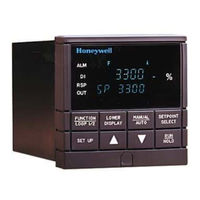
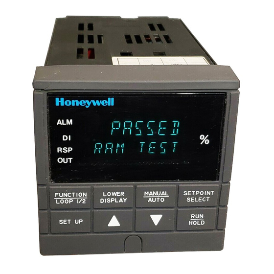
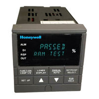
Honeywell UDC3300 Product Manual (294 pages)
Universal Digital Controller
Brand:
Honeywell
| Category:
Controller
| Size: 1.26 MB
Table of Contents
5
Table of Contents
13
Section 1 - Overview
13
Introduction
15
Operator Interface
15
Figure 1-1 Operator Interface Displays and Indicators
16
Table 1-1 Function of Keys
19
Section 2 - Installation
19
Overview
20
Table 2-1 Specifications
24
Model Number Interpretation
24
Figure 2-1 Model Number Interpretation
25
Mounting
25
Figure 2-2 Dimensions
26
Figure 2-3 Mounting Method
26
Table 2-2 Procedure for Mounting the Controller
27
Wiring
28
Table 2-3 Permissible Wiring Bundling
30
Wiring Diagrams
30
Figure 2-4 Composite Wiring Diagram
31
Figure 2-5 Line Voltage Wiring
32
Figure 2-6 Input #1/Input #2 Connections
33
Figure 2-7 Two HLAI Replace 2Nd LLAI Connections
33
Table 2-4 Input 2 Jumper Selections
34
Figure 2-8 Electromechanical Relay Output-Model DC330X-EE-XXX
35
Figure 2-9 Solid State Relay Output-Model DC330X-AA-XX
36
Figure 2-10 10-Amp Solid State Relay Output-Model DC330X-SS-XX
37
Figure 2-11 Open Collector Output-Model DC330X-TT-XXX
38
Figure 2-12 Current Output-Current /Time Duplex, Time/Current Duplex, Position Proportional, or Three Position Step Control
38
Table 2-5 Universal Output Wiring Functionality and Restrictions for Figure 2-12
39
Figure 2-13 Auxiliary Output and Three Relay Outputs
39
Table 2-6 Universal Output Wiring Functionality and Restrictions for Figure 2-13
40
Figure 2-14 Position Proportional Output or Three Position Step-Models DC330X-EE-XXX-X2, DC330X-AA-XXX-X2
41
Figure 2-15 Auxiliary Output Connections-Models DC330X-XX-2XX, DC330X-XX-5XX
41
Figure 2-16 Digital Inputs Connections-Model DC330X-XX-XX3
42
Figure 2-17 Rs422/485/Modbus Communications Option Connections
43
Figure 2-18 DMCS Communications Option Connections
44
Figure 2-19 Transmitter Power for 4-20 Ma 2-Wire Transmitter Using Open Collector Alarm 2 Output-Model DC330X-XT-XXX
45
Figure 2-20 Transmitter Power for 4-20 Ma 2-Wire Transmitter Using Auxiliary Output-Model DC330X-XX-2XX or DC330X-XX-5XX
46
Control and Alarm Relay Contact Information
46
Table 2-7 Control Relay Contact Information
46
Table 2-8 Alarm Relay Contact Information
47
Section 3 - Configuration
47
Overview
48
Configuration Prompts
48
Figure 3-1 Overview of UDC 3300 Prompt Hierarchy
50
How to Get Started
51
Configuration Tips
51
Table 3-1 Configuration Tips
52
Configuration Procedure
52
Table 3-2 Configuration Procedure
54
Loop 1 Tuning Parameters Set Up Group
54
Table 3-3 Tuning Group Function Prompts
56
Loop 2 Tuning Parameters Set Up Group
56
Table 3-4 Tuning Loop 2 Group Function
57
SP Ramp, SP Rate, or SP Programming Set Up Group
57
Table 3-5 SP Ramp Group Function Prompts
59
Accutune Set Up Group
60
Table 3-6 Accutune Group Function Prompts
61
Algorithm Data Set Up Group
61
Table 3-7 Algorithm Group Function Prompts
65
Output Algorithm Parameters Set Up Group
65
Table 3-8 Output Algorithm Group Function Prompts
66
Input 1 Parameters Set Up Group
66
Table 3-9 Input 1 Group Function Prompts
68
Input 2 Parameters Set Up Group
68
Table 3-10 Input 2 Group Function Prompts
69
Input 3 Parameters Set Up Group
69
Table 3-11 Input 3 Group Function
70
Loop 1 Control Parameters Set Up Group
70
Table 3-12 Control Group Function Prompts
72
Loop 2 Control Parameters Set Up Group
72
Table 3-13 Control 2 Group Function Prompts
74
Options Set Up Group
74
Table 3-14 Options Group Function Prompts
76
Communications Set Up Group
76
Table 3-15 Communications Group Function Prompts
78
Alarms Set Up Group
78
Table 3-16 Alarms Group Function Prompts
81
Display Parameters Set Up Group
81
Table 3-17 Display Group Function Prompts
82
Calibration Group
83
Maintenance Set Up Group
83
Table 3-18 Maintenance Group Function Prompts
84
Status Group
85
Configuration Record Sheet Basic Model: DC330B-XX-XXX
85
DMCS Model: DC330D-XX-XXX
87
Configuration Record Sheet Expanded Model: DC330E-XX-XXX
91
Section 4 - Configuration Prompt Definitions
91
Overview
92
Loop 1 Tuning Parameters Set Up Group
92
Table 4-1 Tuning Group Prompt Definitions
96
Loop 2 Tuning Parameters Set Up Group
96
Table 4-2 Loop 2 Tuning Group Prompt
97
Setpoint Ramp/Rate/Programming Set Up Group
97
Table 4-3 Setpoint Ramp/Rate Group Definitions
100
Accutune Set Up Group
100
Table 4-4 Accutune Group Definitions
104
Algorithm Data Set Up Group
104
Table 4-5 Algorithm Group Definitions
114
Figure 4-1 Example of Mass Flow Compensation Using Multiplier/Divider Algorithm
118
Figure 4-2 Example of Eight Segment Characterizer
121
Output Algorithm Parameters Set Up Group
121
Table 4-6 Output Algorithm Group Definitions
124
Input 1 Parameters Set Up Group
124
Table 4-7 Input 1 Group Definitions
128
Input 2 Parameters Set Up Group
128
Table 4-8 Input 2 Group Definitions
129
Input 3 Parameters Set Up Group
129
Table 4-9 Input 3 Group Definitions
130
Loop 1 Control Parameters Set Up Group
130
Table 4-10 Control Group Definitions
136
Loop 2 Control Parameters Set Up Group
136
Table 4-11 Control 2 Group Definitions
141
Options Set Up Group
141
Table 4-12 Options Group Definitions
147
Communications Set Up Group
147
Table 4-13 Communications Group Definitions
151
Alarms Set Up Group
151
Table 4-14 Alarms Group Definitions
155
Display Parameters Set Up Group
155
Table 4-15 Display Group Definitions
156
Calibration Data
156
Maintenance Group
156
Table 4-16 Maintenance Group Definitions
158
Status Test Data
159
Section 5 - Operation
159
Overview
160
How to Power Up the Controller
160
Table 5-1 Power Up Diagnostic Tests
161
Table 5-2 Procedure for Testing the Displays and Keys
162
Entering a Security Code
162
Table 5-3 Procedure for Entering a Security Code
163
Monitoring Your Controller
163
Figure 5-1 Operator Interface
165
Table 5-4 Lower Display Key Parameter
166
Table 5-5 Error Messages
167
Start-Up Procedure
167
Table 5-6 Procedure for Starting Up the Controller
168
Operating Modes
168
Table 5-7 Operating Mode Definitions
169
Table 5-8 Changing Operating Modes
170
Table 5-9 Procedure for Selecting Automatic or Manual Mode
172
Setpoints
172
Table 5-10 Procedure for Selecting the Local Setpoint Source
173
Table 5-11 Procedure for Changing the Local Setpoints
174
Table 5-12 Procedure for Enabling (Or Disabling) the Remote Setpoint
174
Table 5-13 Setpoint Selection Indication
175
Setpoint Ramp Rate
176
Single Setpoint Ramp
176
Table 5-14 Procedure for Configuring a Setpoint Ramp
178
Table 5-15 Procedure for Running a Setpoint Ramp
180
Using Two Sets of Tuning Constants
180
Table 5-16 Procedure for Selecting Two Sets of Tuning Constants
181
Table 5-17 Procedure for Setting Switchover Values
181
Table 5-18 Procedure for Setting Tuning Constant Values
182
Table 5-19 Procedure for Switching PID SETS From the Keyboard
183
Alarm Setpoints
183
Table 5-20 Procedure for Displaying or Changing the Alarm Setpoints
184
Two Loops of Control Overview
184
Table 5-21 Control Loop Selections
185
Figure 5-2 Functional Overview Block Diagram of a Single Loop (Loop #1) or Dual Loop Controller (Loop #1 and Loop #2)
186
Figure 5-3 Functional Overview Block Diagram of Internal Cascade of a 2-Loop Controller
187
Figure 5-4 Hi/Lo Override Selector
187
Table 5-22 Two-Loop Functionality and Restrictions (Model DC330E-EE-2XX or Model DC330E-EE-5XX)
188
Table 5-23 Two-Loop Functionality and Restrictions (Model DC330E-KE-2XX or Model DC330E-KE-5XX)
189
Configuring Two Loops of Control
189
Table 5-24 Procedure for Selecting 2-Loop Algorithm
189
Table 5-25 Procedure for Selecting Output Algorithm
190
Table 5-26 Procedure for Selecting Control Parameters
191
Table 5-27 Procedure for Selecting Tuning Parameters
192
Monitoring Two Loops of Control
192
Table 5-28 Digital Display Indication-Two Loops
193
Operating Two Loops of Control
194
Three Position Step Control Algorithm
194
Table 5-29 Procedure for Displaying the 3PSTEP Motor Position
195
Input Math Algorithms
198
Digital Input Option (Remote Switching)
198
Table 5-30 Digital Input Option Action On Contact Closure
200
Table 5-31 Digital Input Combinations "DIG IN1" or "DIG IN2
201
Table 5-32 Digital Inputs 1 and 2 Combination
202
Auto/Manual Station
202
Figure 5-5 Auto/Manual Station and Backup Control Feature
203
Table 5-33 Auto/Manual Station Mode Configuration Procedure
205
Fuzzy Overshoot Suppression
206
Accutune
207
Table 5-34 Accutune Rules and Regulations
208
Table 5-35 Procedure for Starting TUNE (Demand) Tuning
209
Table 5-36 Procedure for Using TUNE at Start-Up for Duplex
210
Table 5-37 Procedure for Using SP Tuning at Start-Up
211
Table 5-38 Procedure for Using SP Tuning at Start-Up for Duplex
213
Table 5-39 Accutune* Error Prompt Definitions
214
Carbon Potential
215
Figure 5-6 Carbon Potential Control
216
Healthwatch
217
Section 6 - Setpoint Ramp/Soak Programming Option
217
Overview
218
Program Contents
221
Drawing a Ramp/Soak Profile
221
Figure 6-1 Ramp/Soak Profile Example
222
Figure 6-2 Program Record Sheet
223
Entering the Setpoint Program Data
223
Table 6-1 Setpoint Program Data Entry Procedure
224
Table 6-2 Prompt Hierarchy and Available Selections
226
Run/Monitor the Program
226
Table 6-3 Run/Monitor Functions
229
Table 6-4 Procedures for Changing a Running Setpoint Program
231
Section 7 - Input Calibration
231
Overview
232
Minimum and Maximum Range Values
232
Table 7-1 Voltage and Resistance Equivalents for 0% and 100% Range Values
233
Preliminary Information
233
Figure 7-1 Inputs #1, #2, and #3 Wiring Terminals
234
Table 7-2 Equipment Needed
235
Input #1, #2, or #3 Set Up Wiring
235
Figure 7-2 Wiring Connections for Thermocouple Inputs Using an Ice Bath
235
Table 7-3 Set Up Wiring Procedure for Thermocouple Inputs Using an Ice Bath
236
Figure 7-3 Wiring Connections for Thermocouple Inputs Using a Precision Resistor
236
Table 7-4 Set Up Wiring Procedure for Thermocouple Inputs Using a Precision Resistor
237
Figure 7-4 Wiring Connections for RTD
238
Figure 7-5 Wiring Connections for Radiamatic, Millivolts, or Volts (Except 0 to 10 Volts)
239
Figure 7-6 Wiring Connections for 0 to 10 Volt Inputs
240
Figure 7-7 Wiring Connections for 4 to 20 Ma Inputs
241
Input #1, #2, or #3 Calibration Procedure
241
Table 7-5 Input #1, #2, or #3 Calibration Procedure
243
Restoring Factory Calibration
243
Table 7-6 Restoring Factory Calibration
245
Section 8 - Output Calibration
245
Overview
246
Current Proportional Output Calibration
246
Figure 8-1 Wiring Connections for Calibrating Current Proportional Output
246
Table 8-1 Set Up Wiring Procedure Current Proportional Output
247
Table 8-2 Current Proportional Output Calibration Procedure
248
Position Proportional and Three Position Step Output Calibration
249
Table 8-3 Position Proportional and 3 Position Step Output Calibration Procedure
252
Auxiliary Output Calibration
252
Figure 8-2 Wiring Connections for Calibrating Auxiliary Output
252
Table 8-4 Set Up Wiring Procedure for Auxiliary Output
253
Table 8-5 Auxiliary Output Calibration Procedure
255
Section 9 - Troubleshooting / Service
255
Overview
257
Troubleshooting Aids
257
Table 9-1 Error Message Prompts
258
Table 9-2 Procedure for Identifying the Software Version
259
Power-Up Tests
259
Table 9-3 Power-Up Tests
260
Status Tests
260
Table 9-4 Procedure for Displaying the Status Tests Results
261
Table 9-5 Status Tests
262
Background Tests
262
Table 9-6 Background Tests
264
Controller Failure Symptoms
264
Table 9-7 Controller Failure Symptoms
265
Troubleshooting Procedures
265
Table 9-8 Troubleshooting Power Failure Symptoms
266
Table 9-9 Troubleshooting Current Proportional Output Failure
267
Table 9-10 Troubleshooting Position Proportional Output Failure
268
Table 9-11 Troubleshooting Time Proportional Output Failure
269
Table 9-12 Troubleshooting Time/Current or Current/Time Proportional Output Failure
270
Table 9-13 Troubleshooting Alarm Relay Output Failure
271
Table 9-14 Troubleshooting a Keyboard Failure
272
Table 9-15 Troubleshooting a Communications Failure
273
Parts Replacement Procedures
274
Figure 9-1 Chassis Removal
274
Table 9-16 How to Remove the Chassis
275
Figure 9-2 Display/Keyboard Replacement
275
Table 9-17 Display/Keyboard Assembly Replacement Procedure
276
Figure 9-3 Removing the Printed Wiring Boards
276
Table 9-18 Printed Wiring Board Removal From Chassis
277
Figure 9-4 Printed Wiring Board Identification
278
Table 9-19 Second Input Board Replacement Procedure
278
Table 9-20 Power Input Board Replacement Procedure
279
Table 9-21 Digital Input Board Replacement Procedure
280
Table 9-22 Aux.out/Communications Board Replacement Procedure
281
Table 9-23 Mcu/Output Board Replacement Procedure
282
Maintenance
283
Section 10 - Parts List
283
Exploded View
283
Figure 10-1 UDC 3300 Exploded View
284
Table 10-1 Parts Identification
284
Table 10-2 Parts Not Shown
285
Section 11 - Appendix A - Manual Tuning
285
Overview
286
Time, Position, or Current Proportional Simplex Control
286
Table 11-1 Manual Tuning Procedure for Simplex Control
287
Table 11-2 Manual Tuning Formulas
288
Time Proportional Duplex or Current Proportional Duplex Control
288
Two Sets of Tuning Parameters for Single Output Operation
Advertisement
Honeywell UDC3300 Product Manual (120 pages)
Universal Digital Limit Controller
Brand:
Honeywell
| Category:
Controller
| Size: 0.54 MB
Table of Contents
4
Table of Contents
11
Section 1 - Overview
11
Introduction
13
Operator Interface
13
Figure 1-1 Operator Interface Displays and Indicators
14
Table 1-1 Function of Keys
15
Section 2 - Installation
15
Overview
16
Table 2-1 Operating Limits
17
Model Number Interpretation
17
Figure 2-1 Model Number Interpretation
18
Mounting
18
Figure 2-2 Dimensions
19
Figure 2-3 Mounting Method
20
Wiring
20
Table 2-2 Permissible Wiring Bundling
22
Wiring Diagrams
22
Figure 2-4 Composite Wiring Diagram
23
Figure 2-5 Line Voltage Wiring
24
Figure 2-6 Input #1 Connections
25
Figure 2-7 Output and Alarm Wiring
26
Figure 2-8 Digital Input Connections
27
Figure 2-9 RS422/485 Communications Option Connections
28
Figure 2-10 DMCS Communications Option Connections
29
Section 3 - Configuration
29
Overview
30
Configuration Prompts
30
Figure 3-1 Overview of UDC3300 Prompt Hierarchy
31
How to Get Started
32
Configuration Tips
32
Table 3-1 Configuration Tips
33
Configuration Procedure
34
Table 3-2 Configuration Procedure
35
Lockout Set Up Group
35
Table 3-3 Lockout Group Function Prompts
36
Limit Set Up Group
36
Table 3-4 Limit Group Function Prompts
37
Input 1 Parameters Set Up Group
37
Table 3-5 Input 1 Group Function Prompts
39
Communications Set Up Group
39
Table 3-6 Com Group Function Prompts
40
Alarms Set Up Group
40
Table 3-7 Alarms Group Function Prompts
41
Calib Group
41
Status Group
42
Configuration Record Sheet
43
Section 4 - Configuration Prompt Definitions
43
Overview
44
Lockout Data Set Up Group
44
Table 4-1 Lockout Group Prompt Definitions
45
Limit Data Set Up Group
45
Table 4-2 Limit Group Prompt Definitions
46
Input 1 Parameters Set Up Group
46
Table 4-3 Input 1 Group Definitions
50
Communications Set Up Group
50
Table 4-4 Communications Group Definitions
52
Alarms Set Up Group
52
Table 4-5 Alarms Group Definitions
54
Calibration Data
54
Status Test Data
55
Section 5 - Operation
55
Overview
56
How to Power Up the Controller
56
Table 5-1 Power Up Diagnostic Tests
57
Table 5-2 Procedure for Testing the Displays and Keys
58
Enter a Security Code
58
Table 5-3 Procedure for Entering a Security Code
59
How to Operate Your Limit Controller
59
Figure 5-1 Operator Interface
60
Table 5-4 Limit Action Duration or Peak PV Value
61
Table 5-5 Change a Setpoint Value Procedure
62
How to Monitor Your Limit Controller
62
Table 5-6 Error Messages
64
Alarm Setpoints
64
Table 5-7 Procedure for Displaying or Changing the Alarm Setpoints
65
Restarting After Power Loss
67
Section 6 - Input Calibration
67
Overview
68
Minimum and Maximum Range Values
68
Table 6-1 Voltage and Resistance Equivalents for 0% and 100% Range Values
69
Preliminary Information
69
Figure 6-1 Input #1 Wiring Terminals
70
Table 6-2 Equipment Needed
71
Input #1 Set Up Wiring
71
Figure 6-2 Wiring Connections for Thermocouple Inputs Using an Ice Bath
71
Table 6-3 Set Up Wiring Procedure for Thermocouple Inputs Using an Ice Bath
72
Figure 6-3 Wiring Connections for Thermocouple Inputs Using a Precision Resistor
72
Table 6-4 Set Up Wiring Procedure for Thermocouple Inputs Using a Precision Resistor
73
Figure 6-4 Wiring Connections for RTD (Resistance Thermometer Device)
74
Figure 6-5 Wiring Connections for Radiamatic, Millivolts, or Volts (Except 0 to 10 Volts)
75
Figure 6-6 Wiring Connections for 0 to 10 Volt Inputs
76
Figure 6-7 Wiring Connections for 4 to 20 Ma Inputs
77
Input #1 Calibration Procedure
78
Table 6-5 Input #1 Calibration Procedure
79
Section 7 - Troubleshooting / Service
79
Overview
81
Troubleshooting Aids
81
Table 7-1 Error Message Prompts
82
Table 7-2 Procedure for Identifying the Software Version
83
Power-Up Tests
83
Table 7-3 Power-Up Tests
84
Status Tests
84
Table 7-4 Procedure for Displaying the Status Tests Results
85
Table 7-5 Status Tests
86
Background Tests
87
Table 7-6 Background Tests
88
Controller Failure Symptoms
88
Table 7-7 Controller Failure Symptoms
89
Troubleshooting Procedures
89
Table 7-8 Troubleshooting Power Failure Symptoms
90
Table 7-9 Troubleshooting Latching Output Relay Failure
90
Table 7-10 Troubleshooting Alarm Relay Output Failure
91
Table 7-11 Troubleshooting a Keyboard Failure
92
Table 7-12 Troubleshooting a Communications Failure
93
Parts Replacement Procedures
94
Figure 7-1 Chassis Removal
94
Table 7-13 How to Remove the Chassis
95
Figure 7-2 Display/Keyboard Replacement
95
Table 7-14 Display/Keyboard Assembly Replacement Procedure
96
Figure 7-3 Removing the Printed Wiring Boards
96
Table 7-15 Printed Wiring Board Removal From Chassis
97
Figure 7-4 Printed Wiring Board Identification
98
Table 7-16 Power Input Board Replacement Procedure
99
Table 7-17 Digital Input Board Replacement Procedure
100
Table 7-18 Communications Board Replacement Procedure
101
Table 7-19 Mcu/Output Board Replacement Procedure
102
Maintenance
103
Section 8 - Parts List
103
Exploded View
103
Figure 8-1 UDC3300 Exploded View
104
Parts Not Shown
104
Table 8-1 Parts Identification
104
Table 8-2 Parts Not Shown
105
Section 9 - Appendix A How to Apply Digital Instrumentation in Severe Electrical Noise Environments
105
Overview
105
Section 9 - Appendix A - How to Apply Digital Instrumentation in
106
Potential Noise Sources
107
Prevention Methods
108
Recommended Wiring Practices
108
Table 9-1 External Wiring
110
Figure 9-1 Transformer for Digital Equipment
110
Power Source Considerations
111
Noise Suppression at the Source
111
Table 9-2 MOV Devices
112
Figure 9-2 Transient Suppression in Inductive Coils
112
Table 9-3 Coil Voltage Vs Resistor Voltage Rating
113
Figure 9-3 Contact Noise Suppression
114
Figure 9-4 DC Load Noise Suppression
Honeywell UDC3300 User Manual (118 pages)
Universal Digital Controller
Brand:
Honeywell
| Category:
Controller
| Size: 0.53 MB
Table of Contents
3
About This Document
5
Table of Contents
11
1 Introduction
11
Overview
11
CE Conformity (Europe)
11
Figure 1-1 Operator Interface Displays and Indicators
12
Function Keys
12
Table 1-1 Function of Keys
13
2 Installation
13
Mounting
13
Figure 2-1 Dimensions
14
Wiring
14
Figure 2-2 Mounting Method
15
Table 2-1 Permissible Wiring Bundling
16
Figure 2-3 Composite Wiring Diagram
17
Figure 2-4 Line Voltage Wiring
18
Figure 2-5 Input #1/#2 Connections
19
Table 2-2 Input 2 Jumper Selections
19
Figure 2-6 Two HLAI Replace 2Nd LLAI Connections
20
Figure 2-7 Electromechanical Relay Output - Model DC330X-EE-XXX
21
Figure 2-8 Solid State (SS) Relay Output - Model DC33-X-AA-XX
21
Figure 2-9 10-Amp SS External Relay Output - Model DC330X-SS-XX
22
Figure 2-10 Open Collector Output - Model DC330X-TT-XXX
23
Figure 2-11 Current Output Current/Time Duplex, Time/Current Duplex, Position Proportional or Three Position Step Control
23
Figure 2-12 Auxiliary Output and Three-Relay Output
24
Figure 2-13 Position Proportional Output or Three Position Step-Models
25
Figure 2-14 Auxiliary Output Connections-Models DC330X-XX-2XX, DC330X-XX-5XX
25
Figure 2-15 Digital Inputs Connections-Model DC330X-XX-XX3
26
Figure 2-16 RS422/485/ASCII or Modbus Communications Option Connections
27
Figure 2-17 Transmitter Power for 4-20 Ma 2-Wire Transmitter Using Open Collector Alarm 2 Output-Model DC330X-XT-XXX
27
Figure 2-18 Transmitter Power for 4-20 Ma 2-Wire Transmitter Using Auxiliary Output-Model DC330X-XX-2XX or DC330X-XX-5XX
28
Table 2-3 Control Relay Contact Information
28
Table 2-4 Alarm Relay Contact Information
29
3 Configuration
29
Overview
29
Figure 3-1 Prompt Hierarchy
32
Configuration Procedure
32
Table 3-1 Configuration Procedure
33
Loop 1 Tuning Parameters Set Up Group
33
Table 3-2 Loop 1 Tuning Group Function Prompts
35
Loop 2 Tuning Parameters Set Up Group
35
Table 3-3 Loop 2 Tuning Group Function Prompts
37
SP Ramp, SP Rate, or SP Programming Set Up Group
37
Table 3-4 SP Ramp Function Prompts
39
Accutune Set Up Group
39
Table 3-5 Accutune Group Function Prompts
40
Algorithm Data Set Up Group
40
Table 3-6 Algorithm Group Function Prompts
44
Output Algorithm Parameters Set Up Group
44
Table 3-7 Output Algorithm Group Function Prompts
46
Input 1 Parameters Set Up Group
46
Table 3-8 Input 1 Group Function Prompts
47
Input 2 Parameters Set Up Group
47
Table 3-9 Input 2 Group Function Prompts
49
Input 3 Parameters Set Up Group
49
Table 3-10 Input 3 Group Function Prompts
50
Loop 1 Control Parameters Set Up Group
50
Table 3-11 Control Group Function Prompts
52
Loop 2 Control Parameters Set Up Group
52
Table 3-12 Loop 2 Control Parameters Set Up Group
54
Options Set Up Group
54
Table 3-13 Options Group Function Prompt
55
Communications Set Up Group
55
Table 3-14 Communications Group Function Prompts
57
Alarms Set Up Group
57
Table 3-15 Alarms Group Function Prompts
59
Display Parameters Set Up Group
59
Table 3-16 Display Group Function Prompts
60
Calibration Group
60
Maintenance Parameters Set Up Group
60
Table 3-17 Maintenance Group Function Prompts
61
Status Group
63
4 Operation
63
How to Power Up the Controller
63
Monitoring Your Controller
64
Table 4-1 Lower Display Key Parameter Prompts
65
Table 4-2 Error Messages
66
Start-Up Procedure
66
Table 4-3 Procedure for Starting Up the Controller
67
Operating Modes
67
Setpoints
68
Using Two Sets of Tuning Constants
68
Table 4-4 Setpoint Selection Indication
68
Table 4-5 Procedure for Selecting Two Sets of Tuning Constants
68
Table 4-6 Procedure for Setting Switchover Values
69
Table 4-7 Procedure for Setting Tuning Constant Values
69
Table 4-8 Procedure for Switching PID SETS From the Keyboard
70
Alarm Setpoints
70
Two Loops of Control
70
Table 4-9 Procedure for Displaying or Changing the Alarm Setpoints
71
Figure 4-1 Functional Overview Block Diagram of a Single Loop (Loop #1) or Dual Loop Controller (Loop #1 and Loop #2)
72
Figure 4-2 Functional Overview Block Diagram of Internal Cascade of a
73
Table 4-10 Control Loops Selections
74
Table 4-11 Two Loop Functionality and Restrictions (Models DC330E-EE-2XX or DC330E-EE-5XX)
75
Table 4-12 Two Loop Functionality and Restrictions (Models DC330E-KE-2XX or DC330E-KE-5XX)
76
Table 4-13 Procedure for Selecting 2-Loop Algorithm
76
Table 4-14 Procedure for Selecting Output Algorithm
76
Table 4-15 Procedure for Selecting Control Parameters
77
Monitoring Two Loops of Control
77
Table 4-16 Procedure for Selecting Tuning Parameters
77
Table 4-17 Digital Display Indication-Two Loops
78
Operating Two Loops of Control
79
Three Position Step Control Algorithm
79
Input Math Algorithms
79
Table 4-18 Procedure for Displaying the 3PSTEP Motor Position
82
Digital Input Option (Remote Switching)
82
Table 4-19 Digital Input Option Action On Contact Closure
84
Fuzzy Overshoot Suppression
84
Accutune
84
Table 4-20 Digital Input Combinations "DIG IN1" or "DIG IN2
85
Table 4-21 Accutune Rules and Regulations
86
Table 4-22 Procedure for Starting TUNE (Demand) Tuning
87
Table 4-23 Procedure for Using TUNE at Start-Up for Duplex
87
Table 4-24 Procedure for Using SP Tuning at Start-Up
89
Entering a Security Code
89
Table 4-25 Procedure to Enter a Security Code
90
Carbon Potential
90
Figure 4-3 UDC 3300 Controller Being Used to Control the Carbon Potential of a Furnace's Atmosphere
91
Health Watch
93
5 Setpoint Rate/Ramp/Soak Program Operation
93
Setpoint Ramp Rate
93
Single Setpoint Ramp
94
Table 5-1 Procedure for Running a Setpoint Ramp
95
Setpoint Ramp/Soak Programming Option
96
Table 5-2 Program Contents
98
Figure 5-1 Ramp/Soak Profile Example
99
Figure 5-2 Program Record Sheet
100
Table 5-3 Run/Monitor Functions
103
6 Appendix A - Environmental And Operating Conditions
105
7 Appendix B - Model Selection Guide
107
8 Appendix C - Configuration Record Sheet
111
9 Appendix D - Position Proportional Calibration
111
Position Proportional Control Output Calibration
112
Table 9-1 Calibration Procedure
115
10 Appendix E - Input Ranges
Advertisement
Honeywell UDC3300 User Manual (84 pages)
Universal Digital Controller
Brand:
Honeywell
| Category:
Controller
| Size: 0.4 MB
Table of Contents
3
About This Document
5
Table of Contents
9
1 Introduction
9
Overview
9
CE Conformity (Europe)
9
Figure 1-1 Operator Interface Displays and Indicators
10
Function Keys
10
Table 1-1 Function of Keys
11
2 Installation
11
Mounting
11
Figure 2-1 Dimensions
12
Wiring
12
Figure 2-2 Mounting Method
13
Table 2-1 Permissible Wiring Bundling
14
Figure 2-3 Composite Wiring Diagram
15
Figure 2-4 Line Voltage Wiring
16
Figure 2-5 Input #1/#2 Connections
17
Table 2-2 Input 2 Jumper Selections
17
Figure 2-6 Electromechanical Relay Output - Model DC330X-EE-XXX
18
Figure 2-7 Solid State (SS) Relay Output - Model DC33X-AA-XX
18
Figure 2-8 10-Amp SS External Relay Output - Model DC330X-SS-XX
19
Figure 2-9 Open Collector Output - Model DC330X-TT-XXX
20
Figure 2-10 Current Output Current/Time Duplex, Time/Current Duplex, Position Proportional or Three Position Step Control
20
Figure 2-11 Auxiliary Output and Three-Relay Output
21
Figure 2-12 Position Proportional Output or Three Position Step-Models DC330X-EE-XXX-X2, DC330X-AA-XXX-X2
22
Figure 2-13 Auxiliary Output Connections- Models DC330X-XX-2XX
22
Figure 2-14 Digital Inputs Connections-Model DC330X-XX-XX3
23
Figure 2-15 RS422/485/ASCII or Modbus Communications Option Connections
24
Dc330X-XX-5Xx
24
Figure 2-16 Transmitter Power for 4-20 Ma 2-Wire Transmitter Using Open Collector Alarm 2 Output-Model DC330X-XT-XXX
24
Figure 2-17 Transmitter Power for 4-20 Ma 2-Wire Transmitter Using Auxiliary Output-Model DC330X-XX-2XX or DC330X-XX-5XX
25
Table 2-3 Control Relay Contact Information
25
Table 2-4 Alarm Relay Contact Information
27
3 Configuration
27
Overview
27
Figure 3-1 Prompt Hierarchy
29
Configuration Procedure
29
Table 3-1 Configuration Procedure
30
Loop 1 Tuning Parameters Set Up Group
30
Table 3-2 Tuning Group Function Prompts
32
SP Ramp, SP Rate, or SP Programming Set Up Group
32
Table 3-3 SP Ramp Function Prompts
34
Accutune Set Up Group
34
Algorithm Data Set Up Group
34
Table 3-4 Accutune Group Function Prompts
34
Table 3-5 Algorithm Group Function Prompts
36
Output Algorithm Parameters Set Up Group
36
Table 3-6 Output Algorithm Group Function Prompts
37
Input 1 Parameters Set Up Group
37
Table 3-7 Input 1 Group Function Prompts
38
Input 2 Parameters Set Up Group
38
Table 3-8 Input 2 Group Function Prompts
39
Loop 1 Control Parameters Set Up Group
39
Table 3-9 Control Group Function Prompts
41
Options Set Up Group
41
Table 3-10 Options Group Function Prompt
42
Communications Set Up Group
42
Table 3-11 Communications Group Function Prompts
44
Alarms Set Up Group
44
Table 3-12 Alarms Group Function Prompts
46
Display Parameters Set Up Group
46
Calibration Group
46
Status Group
46
Table 3-13 Display Group Function Prompts
47
4 Operation
47
How to Power Up the Controller
47
Monitoring Your Controller
48
Table 4-1 Lower Display Key Parameter Prompts
49
Table 4-2 Error Messages
50
Start-Up Procedure
50
Table 4-3 Procedure for Starting Up the Controller
51
Operating Modes
51
Setpoints
52
Using Two Sets of Tuning Constants
52
Table 4-4 Setpoint Selection Indication
52
Table 4-5 Procedure for Selecting Two Sets of Tuning Constants
52
Table 4-6 Procedure for Setting Switchover Values
53
Table 4-7 Procedure for Setting Tuning Constant Values
53
Table 4-8 Procedure for Switching PID SETS From the Keyboard
54
Alarm Setpoints
54
Three Position Step Control Algorithm
54
Table 4-9 Procedure for Displaying or Changing the Alarm Setpoints
54
Table 4-10 Procedure for Displaying the 3PSTEP Motor Position
55
Input Math Algorithms
56
Digital Input Option (Remote Switching)
56
Table 4-11 Digital Input Option Action On Contact Closure
57
Table 4-12 Digital Input Combinations "DIG IN1" or "DIG IN2
58
Fuzzy Overshoot Suppression
58
Accutune
59
Table 4-13 Procedure for Starting TUNE (Demand) Tuning
60
Entering a Security Code
60
Table 4-14 Procedure for Using TUNE at Start-Up for Duplex
60
Table 4-15 Procedure to Enter a Security Code
61
5 Setpoint Rate/Ramp/Soak Program Operation
61
Setpoint Ramp Rate
61
Single Setpoint Ramp
62
Table 5-1 Procedure for Running a Setpoint Ramp
63
Setpoint Ramp/Soak Programming Option
64
Table 5-2 Program Contents
66
Figure 5-1 Ramp/Soak Profile Example
67
Figure 5-2 Program Record Sheet
68
Table 5-3 Run/Monitor Functions
71
6 Appendix A - Environmental And Operating Conditions
73
7 Appendix B - Model Selection Guide
75
8 Appendix C - Configuration Record Sheet
77
9 Appendix D - Position Proportional Calibration
77
Position Proportional Control Output Calibration
78
Table 9-1 Calibration Procedure
81
10 Appendix E - Input Ranges
Honeywell UDC3300 Instruction Manual (4 pages)
Universal Digital Controller
Brand:
Honeywell
| Category:
Controller
| Size: 0.1 MB
Share and save
Advertisement
Related Products
Honeywell UDC2500
Honeywell UDC330E
Honeywell UDC3500
Honeywell UDC3200 series
Honeywell UDC 1000 Micro-Pro
Honeywell UDC1200 MICRO-PRO
Honeywell UDC1700 MICRO-PRO
Honeywell UDC2000
Honeywell UDC100
Honeywell UEC24014
Honeywell Categories
Thermostat
Controller
Security Camera
Control Unit
Accessories
More Honeywell Manuals
×
Login
Sign In
OR
Sign in with Facebook
Sign in with Google
×
Upload manual
Upload from disk
Upload from URL