Sign In
Upload
Manuals
Brands
Honeywell Manuals
Controller
UDC2500
Honeywell UDC2500 Manuals
Manuals and User Guides for Honeywell UDC2500. We have
4
Honeywell UDC2500 manuals available for free PDF download: Product Manual, Manual, Quick Start Manual
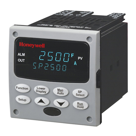
Honeywell UDC2500 Product Manual (243 pages)
Honeywell Universal Digital Controller Product Manual
Brand:
Honeywell
| Category:
Controller
| Size: 1.86 MB
Table of Contents
About this Document
3
World Wide Web
3
Symbol Definitions
4
Table of Contents
5
Introduction
15
Overview
15
Figure 1-1 UDC2500 Operator Interface (All Display Items Shown)
16
Function of Displays and Keys
17
Process Instrument Explorer Software
18
Figure 1-2 Screen Capture of Process Instrument Explorer Running on a Pocket PC
18
CE Conformity (Europe)
19
Figure 1-3 Depiction of Infrared Communications
19
Installation
21
Overview
21
Condensed Specifications
22
Table 2-1 Condensed Specifications
22
Model Number Interpretation
26
Figure 2-1 Model Number Interpretation
27
Control and Alarm Relay Contact Information
28
Table 2-2 Control Relay Contact Information
28
Table 2-3 Alarm Relay Contact Information
28
Mounting
29
Figure 2-2 Mounting Dimensions (Not to Scale)
29
Table 2-4 Mounting Procedure
30
Figure 2-3 Mounting Methods
30
Wiring
31
Electrical Considerations
31
Table 2-5 Permissible Wiring Bundling
32
Wiring Diagrams
33
Table 2-6 Universal Output Functionality and Restrictions
34
Figure 2-4 Composite Wiring Diagram
35
Figure 2-5 Mains Power Supply
36
Figure 2-6 Input 1 Connections
37
Figure 2-7 Input 2 Connections
38
Figure 2-8 Electromechanical Relay Output
38
Figure 2-9 Solid State Relay Output
39
Figure 2-10 Open Collector Output
40
Figure 2-11 Dual Electromechanical Relay Option Output
41
Figure 2-12 Current Output
41
Figure 2-13 Three Position Step Control Connections W/O Dual Relay Option
42
Figure 2-14 Three Position Step Control Connections with Dual Relay Option
42
Figure 2-15 RS-422/485 Communications Option Connections
43
Figure 2-16 Ethernet Communications Option Connections
43
Table 2-7 Terminals for Connecting a UDC to a MDI Compliant Hub or Switch
44
Table 2-8 Terminals for Connecting a UDC Directly to a PC Utilizing a Straight-Through Cable
44
Figure 2-17 Auxiliary Output and Digital Inputs Option Connections
44
Figure 2-19 Transmitter Power for 4-20 Ma - 2 Wire Transmitter Using Auxiliary Output
45
Configuration
46
Overview
46
Table 3-1 Configuration Topics
46
Configuration Prompt Hierarchy
47
Table 3-2 Configuration Prompt Hierarchy
47
Configuration Procedure
48
Table 3-3 Configuration Procedure
48
Tuning Set up Group
49
Table 3-4 TUNING Group (Numeric Code 100) Function Prompts
49
SP Ramp Set up Group
53
Table 3-5 SPRAMP Group (Numeric Code 200) Function Prompts
53
Accutune Set up Group
57
Table 3-6 ATUNE Group (Numeric Code 300) Function Prompts
58
Algorithm Set up Group
60
Table 3-7 ALGOR Group (Numeric Code 400) Function Prompts
60
Output Set up Group
65
Table 3-8 OUTPUT Group (Numeric Code 500) Function Prompts
65
Input 1 Set up Group
69
Table 3-9 INPUT 1 Group (Numeric Code 600) Function Prompts
69
Input 2 Set up Group
73
Table 3-10 INPUT2 Group (Numeric Code 700) Function Prompts
73
Control Set up Group
75
Table 3-11 Table 3-12 CONTRL Group (Numeric Code 800) Function Prompts
75
Options Group
81
Table 3-13 OPTION Group (Numeric Code 900) Function Prompts
81
Communications Group
87
Table 3-14 Communications Group (Numeric Code 1000) Function Prompts
87
Alarms Set up Group
90
Table 3-15 ALARMS Group (Numeric Code 1100) Function Prompts
90
Display Set up Group
96
Table 3-16 DISPLY Group (Numeric Code 1200) Function Prompts
96
Tool Ethernet and Email Configuration Screens
98
Figure 3-1 Ethernet Configuration Screen
98
Figure 3-2 Email Configuration Screen
99
Configuration Record Sheet
101
Introduction
103
Monitoring and Operating the Controller
103
Overview
103
Figure 4-1 Operator Interface
103
Operator Interface
104
Entering a Security Code
104
Lockout Feature
105
Table 4-1 Procedure to Enter a Security Code
105
Monitoring Your Controller
107
Annunciators
107
Table 4-2 Annunciators
107
Viewing the Operating Parameters
108
Table 4-3 Lower Display Key Parameter Prompts
108
Diagnostic Messages
109
Table 4-4 Diagnostic Messages
109
Figure 4-2 Functional Overview Block Diagram of the UDC2500 Controller
110
Single Display Functionality
111
Table 4-5 Single Display Parameters
112
Start up Procedure for Operation
113
Table 4-6 Procedure for Starting up the Controller
113
Control Modes
114
Mode Definitions
114
Table 4-7 Control Mode Definitions
114
What Happens When You Change Modes
115
Setpoints
115
Table 4-8 Changing Control Modes (Dual Display Only)
115
Table 4-9 Procedure for Changing the Local Setpoints
115
Timer
116
Table 4-10 Procedure for Switching between Setpoints
116
Accutune III
118
Tune for Simplex Outputs
119
Tune for Duplex (Heat/Cool)
119
Table 4-11 Procedure for Starting "TUNE
119
Using AUTOMATIC TUNE at Start-Up for Duplex (Heat/Cool)
120
Using BLENDED TUNE at Start-Up for Duplex (Heat/Cool)
120
Table 4-12 Procedure for Using AUTOMATIC TUNE at Start-Up for Duplex Control
120
Using MANUAL TUNE at Start-Up for Duplex (Heat/Cool)
121
Table 4-13 Procedure for Using BLENDED TUNE at Start-Up for Duplex Control
121
Table 4-14 Procedure for Using MANUAL TUNE for Heat Side of Duplex Control
121
Table 4-15 Procedure for Using MANUAL TUNE for Cool Side of Duplex Control
122
Error Codes
123
Table 4-16 Procedure for Accessing Accutune Error Codes
123
Table 4-17 Accutune Error Codes
123
Fuzzy Overshoot Suppression
124
Using Two Sets of Tuning Constants
124
Table 4-18 Set up Procedure
125
Alarm Setpoints
126
Table 4-19 Procedure for Switching PID SETS from the Keyboard
126
Table 4-20 Procedure for Displaying Alarm Setpoints
126
Three Position Step Control Algorithm
127
Table 4-21 Procedure for Displaying 3Pstep Motor Position
127
Setting a Failsafe Output Value for Restart after a Power Loss
128
Table 4-22 Procedure for Setting a Failsafe Value
128
Setting Failsafe Mode
129
Setpoint Rate/Ramp/Program Overview
129
Table 4-23 Procedure for Setting a Failsafe Mode
129
Setpoint Ramp
130
Table 4-24 Running a Setpoint Ramp
130
Setpoint Rate
131
Setpoint Ramp/Soak Programming
132
Table 4-25 Program Contents
132
Figure 4-3 Ramp/Soak Profile Example
135
Figure 4-4 Program Record Sheet
136
Table 4-26 Run/Monitor Functions
137
Tool Maintenance Screens
139
Figure 4-5 Maintenance Data Menu
139
Figure 4-6 Loop Data Maintenance Screen
140
Figure 4-7 Alarm Details Maintenance Screen
141
Figure 4-8 Digital Input Details Screen
142
Figure 4-9 Status Data Maintenance Screen
143
Figure 4-10 Ethernet Status Maintenance Screen
144
Configuring Your Ethernet Connection
145
Figure 4-11 IR Communications Address
145
Figure 4-12 Online Configuration
146
Figure 4-13 Configuration Upload in Progress
146
Figure 4-14 Ethernet Communications Type Selection
147
Figure 4-15 Ethernet Communications Address
148
Figure 4-16 Configuration Upload in Progress
149
Input Calibration
150
Overview
150
Minimum and Maximum Range Values
151
Table 5-1 Voltage, Milliamp and Resistance Equivalents for Input 1 Range Values
151
Preliminary Information
153
Table 5-2 Voltage and Milliamp Equivalents for Input 2 Range Values
153
Table 5-3 Equipment Needed
153
Figure 5-1 Input 1 and Input 2 Wiring Terminals
153
Input 1 Set up Wiring
154
Table 5-4 Set up Wiring Procedure for Thermocouple Inputs Using an Ice Bath
154
Figure 5-2 Wiring Connections for Thermocouple Inputs Using an Ice Bath
154
Table 5-5 Set up Wiring Procedure for Thermocouple Inputs Using Thermocouple Source
155
Table 5-6 Set up Wiring Procedure for RTD Inputs
155
Figure 5-3 Wiring Connections for Thermocouple Inputs Using Thermocouple Source
155
Figure 5-4 Wiring Connections for RTD (Resistance Thermometer Device)
155
Table 5-7 Set up Wiring Procedure for Radiamatic, Millivolts, Volts or Thermocouple Differential Inputs
156
Figure 5-5 Wiring Connections for Radiamatic, Thermocouple Differential, Millivolts or Volts
156
Table 5-8 Set up Wiring Procedure for 0 to 10 Volts
157
Table 5-9 Set up Wiring Procedure for Milliampere Inputs
157
Figure 5-6 Wiring Connections for 0 to 10 Volts
157
Figure 5-7 Wiring Connections for 0 to 20 Ma or 4 to 20 Ma Inputs
157
Input 1 Calibration Procedure
158
Table 5-10 Input 1 Calibration Procedure (Numeric Code 10000)
158
Input 2 Set up Wiring
160
Table 5-11 Set up Wiring Procedure for 0 to 20 Ma or 4 to 20 Ma Inputs - Input 2
160
Figure 5-8 Wiring Connections for 0 to 20 Ma or 4 to 20 Ma Input - Input 2
160
Input 2 Calibration Procedure
161
Table 5-12 Set up Wiring Procedure for 0 to 2 Volts, 0 to 5 Volts, or 1 to 5 Volts - Input 2
161
Figure 5-9 Wiring Connections for 0 to 2 Volts, 0 to 5 Volts or 1 to 5 Volts Input - Input 2
161
Table 5-13 Input 2 Calibration Procedure (Numeric Code 20000)
162
Restore Input Factory Calibration
163
Table 5-14 Restore Factory Calibration
163
Output Calibration
165
Overview
165
Current Output Calibration
166
Table 6-1 Set up Wiring Procedure for Current Output
166
Figure 6-1 Wiring Connections for Calibrating Current Output
166
Table 6-2 Current Output Calibration Procedure (Numeric Code 30000)
167
Auxiliary Output Calibration
168
Table 6-3 Set up Wiring Procedure for Auxiliary Output
168
Figure 6-2 Wiring Connections for Calibrating Auxiliary Output
168
Table 6-4 Auxiliary Output Calibration Procedure (Numeric Code 50000)
169
Restore Output Factory Calibration Procedure
170
Table 6-5 Restore Factory Calibration Procedure
170
Troubleshooting/Service
172
Overview
172
Table 7-16 Software Upgrades
172
Troubleshooting Aids
173
Table 7-1 Procedure for Identifying the Software Version
174
Power-Up Tests
175
Status Tests
175
Table 7-2 Procedure for Displaying the Status Test (Numeric Code 1200) Results
175
Background Tests
176
Table 7-3 Background Tests
176
Controller Failure Symptoms
178
Table 7-4 Controller Failure Symptoms
178
Troubleshooting Procedures
179
Table 7-5 Troubleshooting Power Failure Symptoms
180
Table 7-6 Troubleshooting Current Output Failure
180
Table 7-7 Troubleshooting Three Position Step Control Output Failure
181
Table 7-8 Troubleshooting Time Proportional Output Failure
182
Table 7-9 Troubleshooting Current/Time or Time/Current Proportional Output Failure
183
Table 7-10 Troubleshooting Alarm Relay Output Failure
184
Table 7-11 Troubleshooting a Keyboard Failure
185
Table 7-12 Troubleshooting a RS-485 Communications Failure
186
Table 7-13 Troubleshooting an Ethernet Communications Failure
187
Table 7-14 Troubleshooting Auxiliary Output Failure
187
Restoring Factory Configuration
188
Table 7-15 Restoring Factory Configuration
188
Software Upgrades
189
Parts List
191
Exploded View
191
Figure 8-1 UDC2500 Exploded View
191
Table 8-1 Parts Identification
192
Table 8-2 Parts Not Shown
192
Table 8-3 Software Upgrades (See Section 7.9)
192
Removing the Chassis
193
Modbus Rtu Function Codes
194
Overview
194
General Information
194
Table 9-1 Integer Parameter Type
195
Table 9-2 Floating Point Parameter Type
195
Function Code 20 (14H) - Read Configuration Reference Data
196
Table 9-3 Register Address Format for Function Code 20
197
Read Configuration Examples
198
Function Code 21 (15H) - Write Configuration Reference Data
200
Table 9-4 Register Address Format for Function Code 21
201
Write Configuration Examples
202
Modbus Read, Write and Override Parameters Plus Exception Codes
203
Overview
203
Reading Control Data
204
Read Software Options Status
205
Table 10-1 Control Data Parameters
205
Table 10-2 Option Status
205
Figure 10-1 Software Option Status Information
205
Miscellaneous Read Onlys
206
Register Addresses for Read Onlys
206
Setpoint Program Read Only Information
206
Table 10-3 Miscellaneous Read Onlys
206
Table 10-4 Setpoint Program Read Only Information
206
Setpoints
207
Table 10-5 Setpoint Code Selections
207
Table 10-6 Setpoint Associated Parameters
207
Using a Computer Setpoint (Overriding Controller Setpoint)
208
Table 10-7 Computer Setpoint Selection
208
Table 10-8 Computer Setpoint Associated Parameters
209
Configuration Parameters
210
Tuning
210
Table 10-9 Set-Up Group - Tuning
210
SP Ramp/Rate/Program
212
Table 10-10 Set-Up Group - Setpoint Ramp/Rate
212
Accutune
215
Table 10-11 Set-Up Group - Accutune
215
Algorithm
216
Table 10-12 Set-Up Group - Algorithm
216
Output Algorithms
217
Table 10-13 Set-Up Group - Output
217
Input 1
218
Table 10-14 Set-Up Group - Input 1
218
Input 2
221
Table 10-15 Set-Up Group - Input 2
221
Control
223
Table 10-16 Set-Up Group - Control
223
Options
225
Table 10-17 Set-Up Group - Options
225
Communications
227
Table 10-18 Set-Up Group - Communications
227
Alarms
228
Table 10-19 Set-Up Group - Alarms
228
Display
231
Table 10-20 Set-Up Group - Display
231
Modbus RTU Exception Codes
232
Table 10-21 Modbus RTU Data Layer Status Exception Codes
233
Ethernet Tcp/Ip
234
Overview
234
Further Information
235
Modbus RTU Serial Communications
235
Modbus Messaging on TCP/IP
235
How to Apply Digital Instrumentation in Severe Electrical Noise Environments
235
Index
236
Sales and Service
240
Advertisement
Honeywell UDC2500 Product Manual (108 pages)
Universal Digital Controller
Brand:
Honeywell
| Category:
Controller
| Size: 1.28 MB
Table of Contents
Table of Contents
5
1 Introduction
11
Overview
11
Figure 1-1 UDC2500 Operator Interface
13
Function of Keys
14
Process Instrument Explorer Software
15
Figure 1-2 Screen Capture of Process Instrument Explorer Running on a Pocket PC
15
Figure 1-3 Depiction of Infrared Communications
16
CE Conformity (Europe)
17
2 Installation
19
Overview
19
Condensed Specifications
20
Table 2-1 Condensed Specifications
20
Model Number Interpretation
23
Figure 2-1 Model Number Interpretation
24
Limit and Alarm Relay Contact Information
25
Table 2-2 Limit Relay Contact Information
25
Table 2-3 Alarm Relay Contact Information
25
Mounting
26
Figure 2-2 Mounting Dimensions (Not to Scale)
26
Table 2-4 Mounting Procedure
27
Figure 2-3 Mounting Method
27
Wiring
28
Electrical Considerations
28
Table 2-5 Permissible Wiring Bundling
29
Wiring Diagrams
30
Figure 2-4 Composite Wiring Diagram
30
Figure 2-5 Mains Power Supply
31
Figure 2-6 Input 1 Connections
32
Figure 2-7 Electromechanical Relay Output
33
Figure 2-8 Solid State Relay Output
33
Figure 2-9 Open Collector Output
34
Figure 2-10 RS-422/485 Communications Option Connections
34
Figure 2-11 Ethernet Communications Option Connections
35
Figure 2-12 Auxiliary Output and Digital Inputs Option Connections
35
Figure 2-14 Transmitter Power for 4-20 Ma - 2 Wire Transmitter Using Auxiliary Output
36
Limit Control Application Diagram
37
Figure 2-15 Limit Controller Application Diagram
37
3 Configuration
38
Overview
38
Table 3-1 Configuration Topics
38
Configuration Prompt Hierarchy
39
Table 3-2 Configuration Prompt Hierarchy
39
Configuration Procedure
40
Table 3-3 Configuration Procedure
40
Lock Set up Group
41
Table 3-4 LOCK Group Function Prompts
41
Limit Set up Group
42
Table 3-5 LIMIT Group Function Prompts
42
Input 1 Set up Group
43
Table 3-6 INPUT 1 Group Function Prompts
43
Options Group
47
Table 3-7 OPTION Group Function Prompts
47
Communications Group
49
Table 3-8 Communications Group Function Prompts
49
Alarms Set up Group
53
Table 3-9 ALARMS Group Function Prompts
53
Display Set up Group
57
Table 3-10 DISPLY Group (Numeric Code 1200) Function Prompts
57
Configuration Record Sheet
58
4 Operating the Limit Controller
59
Overview
59
Operator Interface
60
Entering a Security Code
60
Figure 4-1 Operator Interface
60
Lockout Feature
61
Table 4-1 Procedure to Enter a Security Code
61
Monitoring Your Limit Controller
62
Table 4-2 Annunciators
62
Table 4-3 Error Messages
63
Operating Your Limit Controller
64
Table 4-4 Using Contact Input Option
66
Alarm Setpoints
67
Table 4-5 Procedure for Displaying Alarm Setpoints
67
5 Input Calibration
68
Overview
68
Minimum and Maximum Range Values
69
Table 5-1 Voltage, Milliamp and Resistance Equivalents for Input 1 Range Values
69
Preliminary Information
71
Table 5-2 Equipment Needed
71
Figure 5-1 Input 1 Wiring Terminals
71
Input 1 Set up Wiring
72
Table 5-3 Set up Wiring Procedure for Thermocouple Inputs Using an Ice Bath
72
Figure 5-2 Wiring Connections for Thermocouple Inputs Using an Ice Bath
72
Table 5-4 Set up Wiring Procedure for Thermocouple Inputs Using Thermocouple Source
73
Table 5-5 Set up Wiring Procedure for RTD Inputs
73
Figure 5-3 Wiring Connections for Thermocouple Inputs Using Thermocouple Source
73
Figure 5-4 Wiring Connections for RTD (Resistance Thermometer Device)
73
Table 5-6 Set up Wiring Procedure for Radiamatic, Millivolts, Volts or Thermocouple Differential Inputs
74
Figure 5-5 Wiring Connections for Radiamatic, Millivolts, Volts or Thermocouple Differential
74
Table 5-7 Set up Wiring Procedure for 0 to 10 Volts
75
Table 5-8 Set up Wiring Procedure for Milliampere Inputs
75
Figure 5-6 Wiring Connections for 0 to 10 Volts
75
Figure 5-7 Wiring Connections for 0 to 20 Ma or 4 to 20 Ma Inputs
75
Input 1 Calibration Procedure
76
Table 5-9 Input 1 Calibration Procedure
76
Restore Factory Calibration
77
Table 5-10 Restore Factory Calibration
78
6 Output Calibration
79
Overview
79
Auxiliary Output Calibration
79
Table 6-1 Set up Wiring Procedure for Auxiliary Output
80
Figure 6-1 Wiring Connections for Calibrating Auxiliary Output
80
Table 6-2 Auxiliary Output Calibration Procedure
81
7 Troubleshooting/Service
82
Overview
82
Troubleshooting Aids
83
Table 7-1 Procedure for Identifying the Software Version
84
Power-Up Tests
85
Status Tests
85
Table 7-2 Procedure for Displaying the Status Test Results
85
Background Tests
86
Table 7-3 Background Tests
86
Controller Failure Symptoms
88
Table 7-4 Controller Failure Symptoms
88
Troubleshooting Procedures
89
Table 7-5 Troubleshooting Power Failure Symptoms
90
Table 7-6 Troubleshooting Latching Output Relay Failure
91
Table 7-7 Troubleshooting Alarm Relay Output Failure
91
Table 7-8 Troubleshooting a Keyboard Failure
92
Table 7-9 Troubleshooting a RS-485 Communications Failure
93
Table 7-10 Troubleshooting Auxiliary Output Failure
94
Restoring Factory Configuration
95
Table 7-11 Restoring Factory Configuration
95
8 Parts List
96
Exploded View
96
Figure 8-1 UDC2500 Exploded View
96
Table 8-1 Parts Identification
97
Table 8-2 Parts Not Shown
97
Removing the Chassis
98
9 Modbus
99
Overview
99
10 Ethernet Tcp/Ip
100
Overview
100
11 Further Information
101
Modbus Messaging on TCP/IP
101
How to Apply Digital Instrumentation in Severe Electrical Noise Environments
101
Honeywell UDC2500 Manual (8 pages)
Universal Digital Controllers
Brand:
Honeywell
| Category:
Controller
| Size: 0.64 MB
Advertisement
Honeywell UDC2500 Quick Start Manual (2 pages)
Universal Digital Controller
Brand:
Honeywell
| Category:
Controller
| Size: 0.06 MB
Advertisement
Related Products
Honeywell UDC2000
Honeywell UDC2800
Honeywell UDC3300
Honeywell UDC330E
Honeywell UDC3200 series
Honeywell UDC 1000 Micro-Pro
Honeywell UDC1200 MICRO-PRO
Honeywell UDC1700 MICRO-PRO
Honeywell UDC120L
Honeywell UDC100
Honeywell Categories
Thermostat
Controller
Control Unit
Security Camera
Accessories
More Honeywell Manuals
Login
Sign In
OR
Sign in with Facebook
Sign in with Google
Upload manual
Upload from disk
Upload from URL