Honeywell UDC3500 Manuals
Manuals and User Guides for Honeywell UDC3500. We have 5 Honeywell UDC3500 manuals available for free PDF download: Product Manual, Application Note, Instruction, Quick Start Manual

Honeywell UDC3500 Product Manual (460 pages)
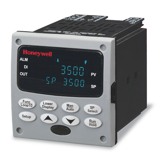
Universal Digital Controller
Brand: Honeywell
|
Category: Controller
|
Size: 2 MB
Table of Contents
-
-
Overview17
-
-
-
-
Overview60
-
-
-
Overview209
-
Lockout Feature211
-
Control Modes217
-
Setpoints218
-
Timer220
-
Accutune III221
-
Alarm Setpoints252
-
Healthwatch259
-
Setpoint Rate260
-
Setpoint Ramp260
-
-
-
Overview293
-
-
RTD Inputs300
-
Milliamperes304
-
-
-
Overview311
-
-
-
Overview323
-
Power-Up Tests326
-
Status Tests326
-
-
-
8 Parts List
351 -
-
Overview354
-
-
-
Overview363
-
Setpoints369
-
-
Tuning Loop 1374
-
Tuning Loop2376
-
Accutune401
-
Algorithm403
-
Math408
-
Logic411
-
Input 1417
-
Input 2419
-
Input 3421
-
Input 4423
-
Input 5425
-
Control427
-
Control Loop 2430
-
Options433
-
Communications437
-
Alarms439
-
Maintenance443
-
Time Event446
-
Display448
-
Clock449
-
-
-
12 Index
453
Advertisement
Honeywell UDC3500 Product Manual (422 pages)
Universal Digital Controller
Brand: Honeywell
|
Category: Controller
|
Size: 5 MB
Table of Contents
-
-
Overview15
-
-
-
-
Overview57
-
-
-
Overview195
-
Lockout Feature197
-
Key Error198
-
Control Modes203
-
Setpoints204
-
Timer206
-
Accutune III207
-
Accutune207
-
-
Output Override233
-
Alarm Setpoints236
-
Carbon Potential242
-
Healthwatch244
-
Setpoint Rate245
-
Setpoint Ramp245
-
Pv Hot Start245
-
Run/Hold Key245
-
Program Contents247
-
Totalizer Data264
-
-
-
Overview271
-
-
RTD Inputs278
-
Milliamperes282
-
-
-
Overview289
-
-
-
Overview301
-
Power-Up Tests304
-
Status Tests304
-
-
-
8 Parts List
330 -
-
Overview333
-
Register Count334
-
-
-
Overview342
-
Setpoints347
-
-
Tuning Loop 1352
-
Tuning Loop2354
-
Accutune362
-
Algorithm364
-
Math369
-
Logic372
-
Input 1378
-
Input 2380
-
Input 3382
-
Input 4384
-
Input 5386
-
Control388
-
Control Loop 2391
-
Options394
-
Communications398
-
Alarms400
-
Maintenance405
-
Time Event408
-
Display410
-
Clock411
-
-
-
12 Index
415

Honeywell UDC3500 Application Note (16 pages)
Brand: Honeywell
|
Category: Controller
|
Size: 0 MB
Advertisement

Honeywell UDC3500 Quick Start Manual (6 pages)
Universal Digital Controller
Brand: Honeywell
|
Category: Controller
|
Size: 0 MB
Table of Contents

Honeywell UDC3500 Instruction (8 pages)
Universal Digital Controller
Printed Wiring Board Replacements
Brand: Honeywell
|
Category: Controller
|
Size: 0 MB