Table of Contents
Advertisement
Quick Links
Advertisement
Table of Contents

Related Manuals for Honeywell DC33XB


Summary of Contents for Honeywell DC33XB
- Page 1 UDC3300 Basic Model: DC33XB User Manual 51-52-25-99 12/00...
- Page 2 Chassis Ground. Identifies a connection to the chassis or frame of the equipment shall be bonded to Protective Earth at the source of supply in accordance with national and local electrical code requirements. UDC3300 Basic Model: DC33XB User Manual 12/00...
-
Page 3: Table Of Contents
OPERATION ....................... 39 4.1 How to Power Up the Controller ...................39 4.2 Monitoring Your Controller....................39 4.3 Start-up Procedure.......................42 4.4 Operating Modes......................43 4.5 Setpoints ........................43 4.6 Using Two Sets of Tuning Constants ................44 4.7 Alarm Setpoints......................46 12/00 UDC3300 Basic Model: DC33XB User Manual... - Page 4 APPENDIX C – CONFIGURATION RECORD SHEET ........67 APPENDIX D – POSITION PROPORTIONAL CALIBRATION ......69 9.1 Position Proportional Control Output Calibration ............69 APPENDIX E – INPUT RANGES................ 73 CE MARK MULTILANGUAGE SAFETY SHEETS UDC3300 Basic Model: DC33XB User Manual 12/00...
- Page 5 Table 4-14 Procedure for Using TUNE at Start-up for Duplex_________________________52 Table 4-15 Procedure to Enter a Security Code ___________________________________52 Table 5-1 Procedure for Running a Setpoint Ramp_________________________________54 Table 5-2 Program Contents __________________________________________________56 Table 5-3 Run/Monitor Functions_______________________________________________60 Table 9-1 Calibration Procedure _______________________________________________70 12/00 UDC3300 Basic Model: DC33XB User Manual...
- Page 6 Alarm 2 Output—Model DC330X-XT-XXX _____________________________16 Figure 2-17 Transmitter Power for 4-20 mA 2-wire Transmitter Using Auxiliary Output—Model DC330X-XX-2XX or DC330X-XX-5XX ____________________16 Figure 3-1 Prompt Hierarchy __________________________________________________19 Figure 5-1 Ramp/Soak Profile Example__________________________________________58 Figure 5-2 Program Record Sheet______________________________________________59 UDC3300 Basic Model: DC33XB User Manual 12/00...
-
Page 7: Introduction
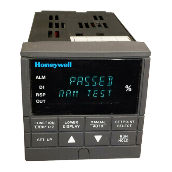
• If PV is equal to or greater than LOOP 1/2 DISPLAY SELECT AUTO ±10% deviation, the center bar Keys - See Table 1-1 plus all ten deviation bars will SET UP light. HOLD Figure 1-1 Operator Interface Displays and Indicators 12/00 UDC3300 Basic Model: DC33XB User Manual... -
Page 8: Function Keys
Hold key down to cycle through configured setpoints. SELECT • Alternate action switch initiates or holds the Setpoint Ramp or Setpoint HOLD Program. • Acknowledges a latched alarm 1. Increases the selected parameter value. Decreases the selected parameter value. UDC3300 Basic Model: DC33XB User Manual 12/00... -
Page 9: Installation
FUNCTION LOWER SETPOINT AUTO L1/L2 DISPLAY SELECT SET UP HOLD Max Panel 2.4 with optional .945 Thickness .093 Max (2) rear cover .394 90.7 3.57 21.6 147.3 .850 24152 5.82 Figure 2-1 Dimensions 12/00 UDC3300 Basic Model: DC33XB User Manual... -
Page 10: Wiring
National and local electrical codes. To minimize electrical noise and transients that may adversely affect the system, supplementary bonding of the controller enclosure to a local ground, using a No. 12 (4 mm ) copper conductor, is recommended. UDC3300 Basic Model: DC33XB User Manual 12/00... -
Page 11: Table 2-1 Permissible Wiring Bundling
• 4-20 mA output signal wiring • Slidewire feedback circuit wiring • Digital input signals • Communications • Low voltage alarm relay output wiring • Low voltage wiring to solid state type control circuits 12/00 UDC3300 Basic Model: DC33XB User Manual... -
Page 12: Figure 2-3 Composite Wiring Diagram
(Do not use for See Figure 2-13 Transmitters Communications shield) • Using Alarm 2 Output See Figure 2-16 Communications Terminals • Using Auxiliary Output See Figure 2-15 See Figure 2-17 Figure 2-3 Composite Wiring Diagram UDC3300 Basic Model: DC33XB User Manual 12/00... -
Page 13: Figure 2-4 Line Voltage Wiring
Provide a switch and non-time delay (North America), quick-acting, high breaking capacity, Type F (Europe), 1/2A, 250V fuse(s) or circuit-breaker for 90-264V; or 1A, 125V fuse or circuit breaker for 24 Vac/dc operation, as part of the installation. Figure 2-4 Line Voltage Wiring 12/00 UDC3300 Basic Model: DC33XB User Manual... -
Page 14: Figure 2-5 Input #1/#2 Connections
Input 1 as the 0–10 100K Xmitter option, use Input 1 as the Carbon Probe input. Volt Carbon Probe input. 250Ω source Power – 100K – – – Supply Figure 2-5 Input #1/#2 Connections UDC3300 Basic Model: DC33XB User Manual 12/00... -
Page 15: Table 2-2 Input 2 Jumper Selections
Electromechanical relays are rated at 5 Amps @120 Vac or 30 Vdc and 2.5 Amps at 240 Vac. Customer should size fuses accordingly. Use Fast Blo fuses only. Figure 2-6 Electromechanical Relay Output – Model DC330X-EE-XXX 12/00 UDC3300 Basic Model: DC33XB User Manual... -
Page 16: Figure 2-7 Solid State (Ss) Relay Output - Model Dc33X-Aa-Xx
55°C. Customer Black should size fuses Output 1 accordingly. Use – White Fast Blo fuses – only. Output 2 – Solid State Relay Green Figure 2-8 10-amp SS External Relay Output — Model DC330X-SS-XX UDC3300 Basic Model: DC33XB User Manual 12/00... -
Page 17: Figure 2-9 Open Collector Output - Model Dc330X-Tt-Xxx
Electromechanical relays are rated at 5 Amps @120 Vac or 30 Vdc and 2.5 Amps at 240 Vac. Customer should size fuses accordingly. Use Fast Blo fuses only. Figure 2-9 Open Collector Output — Model DC330X-TT-XXX 12/00 UDC3300 Basic Model: DC33XB User Manual... -
Page 18: Figure 2-10 Current Output Current/Time Duplex, Time/Current Duplex, Position Proportional Or Three Position Step Control
Electromechanical relays are rated at 5 Amps @120 Vac or 2.5 Amps at 240 Vac. Customer should size fuses accordingly. Use Fast Blo fuses only. All current outputs are isolated from each other, case ground, and all inputs. 24160 Figure 2-11 Auxiliary Output and Three-Relay Output UDC3300 Basic Model: DC33XB User Manual 12/00... -
Page 19: Figure 2-12 Position Proportional Output Or Three Position Step-Models
Electrical noise suppression may be required. Slidewire input is not required for Three Position Step control but can be used for motor position indication. Figure 2-12 Position Proportional Output or Three Position Step— Models DC330X-EE-XXX-X2, DC330X-AA-XXX-X2 12/00 UDC3300 Basic Model: DC33XB User Manual... -
Page 20: Figure 2-13 Auxiliary Output Connections- Models Dc330X-Xx-2Xx
Figure 2-13 Auxiliary Output Connections— Models DC330X-XX-2XX, DC330X-XX-5XX Digital Inputs Digital Input Switch #1 Digital Input Switch #2 Connect shield to ground at one end only Switch Common Figure 2-14 Digital Inputs Connections—Model DC330X-XX-XX3 UDC3300 Basic Model: DC33XB User Manual 12/00... -
Page 21: Figure 2-15 Rs422/485/Ascii Or Modbus Communications Option Connections
RX– TX– Resistor To Other Use shielded twisted pair Communication cables (Belden 9271 Instruments 120 Ohm Resistor Twinax or equivalent) (maximum 31) on Last Leg Figure 2-15 RS422/485/ASCII or Modbus Communications Option Connections 12/00 UDC3300 Basic Model: DC33XB User Manual... -
Page 22: Dc330X-Xx-5Xx
2-wire ZERO VAL = 4095 Zener Diode Transmitter SPAN VAL = 4095 – – – 250 ohm resistor Figure 2-17 Transmitter Power for 4-20 mA 2-wire Transmitter Using Auxiliary Output—Model DC330X-XX-2XX or DC330X-XX-5XX UDC3300 Basic Model: DC33XB User Manual 12/00... -
Page 23: Table 2-3 Control Relay Contact Information
Table 2-4 Alarm Relay Contact Information Variable Variable Alarm NOT in Alarm State in Alarm State Unit Relay Power Relay Relay Wiring Indicators Indicators Contact Contact N.O. Open Open N.C. Closed Closed N.O. Closed Open N.C. Open Closed 12/00 UDC3300 Basic Model: DC33XB User Manual... - Page 24 Installation UDC3300 Basic Model: DC33XB User Manual 12/00...
-
Page 25: Configuration
CONT ALG TIMER PERIOD START L DISP INP ALG1 MATH K CALC HI CALC LO ALG1 INA ALG1 INB ALG1 INC ALG1BIAS PCT CO OUT ALG OUT ALG 4-20 RNG RLYSTATE RLY TYPE 12/00 UDC3300 Basic Model: DC33XB User Manual... - Page 26 A2S1 EV A2S2 H L A2S2 EV AL HYST ALM OUT1 BLOCK DISPLAY DECIMAL TEMPUNIT PWR FREQ RATIO 2 LANGUAGE CALIB USED FOR FIELD CALIBRATION STATUS VERSON FAILSAFE RAM TEST CONFTEST CALTEST FACT CRC UDC3300 Basic Model: DC33XB User Manual 12/00...
-
Page 27: Configuration Procedure
Exit Exits configuration mode and returns the controller LOWER Configuration to the same state it was in immediately preceding DISPLAY entry into the Set Up mode. It stores any changes you have made. 12/00 UDC3300 Basic Model: DC33XB User Manual... -
Page 28: Loop 1 Tuning Parameters Set Up Group
1.00 RSET2MIN Reset 2 in repeats/minute RSET2RPM Cycle Time (Heat) 1 to 120 CYC SEC CYC SX3 Cycle Time (Cool) 1 to 120 CYC2 SEC CYC2 SX3 SECURITY Security Code 0 to 4095 UDC3300 Basic Model: DC33XB User Manual 12/00... - Page 29 NONE CALIB LOCKOUT CALIB + CONF + VIEW Manual/Auto Key Lockout DISABL ENABLE AUTO MAN ENABLE Setpoint Select Key DISABL ENABLE SP SEL Lockout ENABLE Run/Hold Key Lockout DISABL ENABLE RUN HOLD ENABLE 12/00 UDC3300 Basic Model: DC33XB User Manual...
-
Page 30: Sp Ramp, Sp Rate, Or Sp Programming Set Up Group
Always end in a soak segment (2, 4, ... 12) Engineering Units for TIME (hours.minutes) TIME RAMPUNIT Ramp Segments EU/MIN (engineering units/minute) EU/HR (engineering units/hour) Number of Program 0 to 99 recycles –– RECYCLES Recycles UDC3300 Basic Model: DC33XB User Manual 12/00... - Page 31 –– SEG 3, 5, 7, 9 & 11 RAMP SEG 3, 5, 7, 9, & 11 RATE SEG 4, 6, 8, 10 & 12 SP SEG 4, 6, 8, 10 & 12 TIME 12/00 UDC3300 Basic Model: DC33XB User Manual...
-
Page 32: Accutune Set Up Group
Timer Enable/Disable ENABLE DISABL DISABL PERIOD Timeout Period 00:00 to 99:59 00:01 START Start Initiation KEY (Run/Hold key) ALARM2 Lower Display Selection TI REM (time remaining) TI REM L DISP E time (elapsed time) UDC3300 Basic Model: DC33XB User Manual 12/00... - Page 33 INP 1 INP 2 LP1OUT IN AL1 PCT CO Percent Carbon Monoxide 0.020 to 0.350 (fractional 0.200 percent of CO) Input Algorithm 1 Bias -999 to 9999 floating (in 0.000 ALG1BIAS engineering units) 12/00 UDC3300 Basic Model: DC33XB User Manual...
-
Page 34: Output Algorithm Parameters Set Up Group
2 are both energized) Relay Cycle Time MECHAN (Cycle time in one MECHAN RLY TYPE Increments second increments) SOL ST (Cycle time in 1/3 second increments: 1 = .33 seconds, 120 = 40 seconds) UDC3300 Basic Model: DC33XB User Manual 12/00... -
Page 35: Input 1 Parameters Set Up Group
BIAS IN1 Input 1 Bias –999. to 9999. (in engineering units) FILTER 1 Input 1 Filter 0 to 120 seconds Burnout Protection NONE DOWN NONE BURNOUT1 NO_FS EMISSIV1 Emissivity 0.01 to 1.00 0.00 12/00 UDC3300 Basic Model: DC33XB User Manual... -
Page 36: Input 2 Parameters Set Up Group
Input 2 Bias –999. to 9999. BIAS IN2 (in engineering units) Input 2 Filter 0 to 120 seconds FILTER 2 Burnout Protection NONE DOWN NONE BURNOUT2 NO_FS Emissivity 0.01 to 1.00 0.00 EMISSIV2 UDC3300 Basic Model: DC33XB User Manual 12/00... -
Page 37: Loop 1 Control Parameters Set Up Group
Control Output Direction DIRECT REVRSE ACTION REVRSE Output Change Rate ENABLE DISABL OUT RATE DISABL Does not apply to 3 Position Step Control algorithm. Output Rate Up Value 0 to 9999% per minute PCT/M UP 12/00 UDC3300 Basic Model: DC33XB User Manual... - Page 38 Within the range of output limits for Manual Output Power-up Preset Output Within the range of output limits AUTO OUT for Automatic Output Proportional Band or Gain PB PCT GAIN PBorGAIN Units GAIN MINorRPM Reset Units UDC3300 Basic Model: DC33XB User Manual 12/00...
-
Page 39: Options Set Up Group
+ToSP2 DISABL DIG1 COM Combinations +PID2 +ToSP1 +ToDIR +RUN Digital 2 Input Selections Same as DIG IN 1 NONE DIG IN 2 Digital Input 2 Same as DIG1 COM DISABL DIG2 COM Combinations 12/00 UDC3300 Basic Model: DC33XB User Manual... -
Page 40: Communications Set Up Group
Duplex Operation HALF HALF DUPLEX FULL ATTENTION • When ComSTATE = MODBUS, this selection is fixed at HALF. • When the RS422/485/Auxiliary output option board is installed, this selection is fixed at HALF. UDC3300 Basic Model: DC33XB User Manual 12/00... - Page 41 Communication Units PERCNT PERCNT CSP RATO Loop 1 Computer Setpoint –20.0 to 20.0 Ratio Loop 1 Computer Setpoint –999. to 9999. CSP BIAS Bias (in engineering units) Local Loop Back DISABL DISABL LOOPBACK ENABLE 12/00 UDC3300 Basic Model: DC33XB User Manual...
-
Page 42: Alarms Set Up Group
NONE Alarm 1, Setpoint 1 State HIGH A1S1 H L HIGH SP Programming Event BEGIN A1S1 EV Alarm State for Alarm 1, Setpoint 1 A1S2 H L Alarm 2, Setpoint 1 State HIGH UDC3300 Basic Model: DC33XB User Manual 12/00... - Page 43 ALM OUT1* Latching Alarm for NO LAT NO LAT Output 1 LATCH Alarm Blocking DISABL DISABL BLOCK BLOCK1 BLOCK2 BLK 12 * For CE Conformity, Performance Criteria A, Select NO LAT 12/00 UDC3300 Basic Model: DC33XB User Manual...
-
Page 44: Display Parameters Set Up Group
3.15 Calibration Group The prompts used here are for field calibration purposes. 3.16 Status Group The prompts used here are read only. They are used to determine the reason for a controller failure. UDC3300 Basic Model: DC33XB User Manual 12/00... -
Page 45: Operation
Press the LOWER DISPLAY key to scroll through the operating parameters listed in Table 4-1. The lower display will show only those parameters and their values that apply to your specific model and the way in which it was configured. 12/00 UDC3300 Basic Model: DC33XB User Manual... -
Page 46: Table 4-1 Lower Display Key Parameter Prompts
BIAS—Displays the manual reset value for algorithm PD+MR. TUNE OFF LIMIT CYCLE TUNING NOT RUNNING—Appears when Accutune is disabled. LIMIT CYCLE TUNING RUNNING—Appears when Accutune is enabled. TUNE RUN RESET SP PROGRAM TO BEGINNING OF FIRST SEGMENT ToBEGIN UDC3300 Basic Model: DC33XB User Manual 12/00... -
Page 47: Table 4-2 Error Messages
RV = (RV source x RV source ratio) + RV source bias Segment Error—SP Program starting segment number is less than ending SEG ERR segment number. Not calibrated. Perform Position Proportional calibration. CAL MTR 12/00 UDC3300 Basic Model: DC33XB User Manual... -
Page 48: Start-Up Procedure
• Using the Digital Input, if configured. If it is necessary to stop or abort the tuning process, press the MANUAL/AUTO key and the controller will return to manual mode. UDC3300 Basic Model: DC33XB User Manual 12/00... -
Page 49: Operating Modes
If another key is pressed after changing the LSP value, then the value is stored immediately. 12/00 UDC3300 Basic Model: DC33XB User Manual... -
Page 50: Using Two Sets Of Tuning Constants
Select until you see the switchover value in the Upper Display FUNCTION Switchover and SW VALUE in the Lower Display. LOOP 1/2 value function to select the switchover value in the upper display. UDC3300 Basic Model: DC33XB User Manual 12/00... -
Page 51: Table 4-7 Procedure For Setting Tuning Constant Values
PV value displayed in the Upper LOWER PID set Display and the PIDSETx in the Lower Display. DISPLAY display to change PIDSET1 to PIDSET2 or vice versa. You can use Accutune on each set. 12/00 UDC3300 Basic Model: DC33XB User Manual... -
Page 52: Alarm Setpoints
Table 4-10 Procedure for Displaying the 3PSTEP Motor Position Step Operation Press Action Access the until you see the PV Value in the Upper Display and LOWER displays either POS or OUT in the Lower Display. DISPLAY UDC3300 Basic Model: DC33XB User Manual 12/00... -
Page 53: Input Math Algorithms
Input A, Input B, and Input C selections for these formulas are found in Section 3 – Configuration; Set Up group ALGORTHM, under the following function prompts: ALG1 INA ALG1 INB ALG1 INC 12/00 UDC3300 Basic Model: DC33XB User Manual... -
Page 54: Digital Input Option (Remote Switching)
Unit goes to manual mode, output goes to the failsafe value. Disables all keys. ToLOCK LOCKED when a key is pressed ToAout Output is forced to value set at control prompt “AUTO OUT” when controller is in automatic mode. UDC3300 Basic Model: DC33XB User Manual 12/00... -
Page 55: Table 4-12 Digital Input Combinations "Dig In1" Or "Dig In2
PIDSET 2 in lower display Puts the controller into direct action. +ToDIR Selects the second local setpoint. +ToSP2 RSP blinks +ToSP1 Selects the local setpoint. +RUN R indicator blinks Starts or restarts RUN of SP RMP/PROG. 12/00 UDC3300 Basic Model: DC33XB User Manual... -
Page 56: Fuzzy Overshoot Suppression
• Setpoint changes can be made during operation. The setpoint at the time tuning starts is captured and Tune runs until completion, then proceeds to the new SP value following the completion of tuning. UDC3300 Basic Model: DC33XB User Manual 12/00... -
Page 57: Table 4-13 Procedure For Starting Tune (Demand) Tuning
50% for HEAT or between 50% and the low output limit for COOL while allowing only a small process variable change above and below the setpoint during each cycle. Configuring TUNE for Duplex (Heat/Cool) To configure this item, refer to Section 3 – Configuration. 12/00 UDC3300 Basic Model: DC33XB User Manual... -
Page 58: Entering A Security Code
Upper Display = 0 FUNCTION Up Group Lower Display = SECUR LOOP 1/2 Security Code To enter a four digit number in the upper display (0001 to Entry 4095) This will be your security code. UDC3300 Basic Model: DC33XB User Manual 12/00... -
Page 59: Setpoint Rate/Ramp/Soak Program Operation
Configuration Check Make sure you: • enable SP RAMP • disable SP RATE and SP PROG • set the ramp time in minutes • set the final setpoint value See Section 3.4 for details. 12/00 UDC3300 Basic Model: DC33XB User Manual... -
Page 60: Table 5-1 Procedure For Running A Setpoint Ramp
“R” changes to “H” in the upper display and the controller operates at the new setpoint. Return to normal After the SP Ramp has completed, disable operating mode the SP RAMP function, then press the LOWER DISPLAY key. UDC3300 Basic Model: DC33XB User Manual 12/00... -
Page 61: Setpoint Ramp/Soak Programming Option
The program is placed in hold at the beginning of the first segment in the program. The mode will be as configured under PWR MODE in the Control function group. 12/00 UDC3300 Basic Model: DC33XB User Manual... -
Page 62: Table 5-2 Program Contents
This function determines the status of the controller upon completion. The Program selections are: Termination • State LASTSP = controls to last setpoint and last control mode • F SAFE = manual mode, failsafe output UDC3300 Basic Model: DC33XB User Manual 12/00... - Page 63 ENABL = present PV value is used as beginning setpoint value for the ramp segment When enabled, this selection allows you to reset the program to the Reset Program beginning or rerun it from the keyboard. to Beginning 12/00 UDC3300 Basic Model: DC33XB User Manual...
-
Page 64: Figure 5-1 Ramp/Soak Profile Example
SG10 TIME Soak Time 0hr.:30min. SEG2 SP Soak SP SG11RAMP Ramp Time 3hr.:30min. SEG2TIME Soak Time 1hr.:30min. SG12 SP Soak SP SEG3RAMP Ramp Time 1hr. SG12TIME Soak Time 0hr.:30min. SEG4 SP Soak SP UDC3300 Basic Model: DC33XB User Manual 12/00... -
Page 65: Figure 5-2 Program Record Sheet
SPP SEG1RAMP Ramp Time SG10 TIME Soak Time SEG2 SP SG11RAMP Soak SP Ramp Time SEG2TIME SG12 SP Soak Time Soak SP SEG3RAMP Ramp Time SG12TIME Soak Time SEG4 SP Soak SP 12/00 UDC3300 Basic Model: DC33XB User Manual... -
Page 66: Table 5-3 Run/Monitor Functions
Reopening the contact has no effect and places the program in HOLD mode. The setpoint is changed to what the setpoint was when the program was first started. restarts the Setpoint Program. HOLD UDC3300 Basic Model: DC33XB User Manual 12/00... - Page 67 (if configured for disable of setpoint programming). The controller operates at the last setpoint in the program in automatic or will be in manual mode at the failsafe output. Disable Program See Section 3.4 for details. 12/00 UDC3300 Basic Model: DC33XB User Manual...
- Page 68 Setpoint Rate/Ramp/Soak Program Operation UDC3300 Basic Model: DC33XB User Manual 12/00...
-
Page 69: Appendix A - Environmental And Operating Conditions
Special Conditions I/O, and computer interface circuits. (Europe) * The maximum rating only applies up to 40 °C (104 °F). For higher temperatures, the RH specification is derated to maintain constant moisture content. 12/00 UDC3300 Basic Model: DC33XB User Manual... - Page 70 Environmental and Operating Conditions UDC3300 Basic Model: DC33XB User Manual 12/00...
-
Page 71: Appendix B - Model Selection Guide
None – 1 = T/C, RTD, Radiamatic, mV, 0-5V, 1-5V, 0-20 mA, 4-20 mA – 2 = Slidewire Input – 3 = T/C, RTD, Radiamatic, mV, 0-5V, 1-5V, 0-20 mA, 4-20 mA, 0-10V 12/00 UDC3300 Basic Model: DC33XB User Manual... - Page 72 Model Selection Guide UDC3300 Basic Model: DC33XB User Manual 12/00...
-
Page 73: Appendix C - Configuration Record Sheet
IN2 LO _________ SP PROG _________ DISABL RATIO 2 _________ 1.00 BIAS IN2 _________ FILTER 2 _________ FUZZY _________ DISABL ACCUTUNE BURNOUT2 _________ NONE ACCUTUNE _________ DISABL EMISSIV2 _________ 0.00 AT ERROR Read Only 12/00 UDC3300 Basic Model: DC33XB User Manual... - Page 74 NO LAT DIG IN 2 _________ NONE BLOCK _________ DISABL DIG2 COM _________ DISABL DISPLAY DECIMAL _________ XXXX TEMPUNIT _________ NONE PWR FREQ _________ 60 HZ RATIO 2 _________ DISABL LANGUAGE _________ ENGLIS UDC3300 Basic Model: DC33XB User Manual 12/00...
-
Page 75: Appendix D - Position Proportional Calibration
Motor Position Indication, follow the entire calibration procedure. ATTENTION These prompts only appear when position OUT ALG is selected. If motor position for 3PSTEP is desired, first configure unit for “position.” After calibration the unit can be switched to 3PSTEP. 12/00 UDC3300 Basic Model: DC33XB User Manual... -
Page 76: Table 9-1 Calibration Procedure
Set 0% value 0% position. LOOP 1/2 Upper Display: (Counts of Feedback Slidewire-0 to 3000) Lower Display: ZERO VAL When the motor stops, the display should stop counting, then go to the next step. UDC3300 Basic Model: DC33XB User Manual 12/00... - Page 77 For manual calibration, the motor does not move from its position prior to the start of Position Proportional calibration. Exit the The controller will store the 100 % value. FUNCTION Calibration LOOP 1/2 Mode To exit the calibration mode. LOWER DISPLAY SETUP 12/00 UDC3300 Basic Model: DC33XB User Manual...
- Page 78 Position Proportional Calibration UDC3300 Basic Model: DC33XB User Manual 12/00...
-
Page 79: Appendix E - Input Ranges
0 to 50 mV 1 to 5 V Volts 0 to 5 V 0 to 10 V 0 to 1250 mV Carbon Oxygen –30 to510 mV *User enters the range manually per RI type and application 12/00 UDC3300 Basic Model: DC33XB User Manual... - Page 80 Input Ranges UDC3300 Basic Model: DC33XB User Manual 12/00...
- Page 81 DA2I-6042 SIKKERHEDSKRAV For at reducere risikoen for elektrisk stød og dermed forbundet personskade er det nødvendigt at følge sikkerhedsforskrifterne i følgende dokumentation. Dette symbol advarer brugeren om en potentiel berøringsfare, såfremt der kan være adgang til den livsfarlige netspænding. Klemme til beskyttelsesjord. Til tilslutning af ledning til forsyningssystemets jordfor- bindelse.
- Page 82 Terminals for vekselstrøm linienet Input # 2 terminals ; 2 HLAI terminals Input # 1 terminal Strøm til 2 emitter (trådledning) for 4 - 20 mA Digitale input terminals Terminals for outputs og alarm Hjaelpe terminals for outputs Kommunikations terminals...
- Page 83 TURVALLISUUSMÄÄRÄYKSET FI2I-6042 Noudata kaikkia näitä turvaohjeita vammoja aiheuttavien sähköiskujen välttämiseksi Tämä merkki varoittaa käyttäjää sähköiskun vaarasta paikassa, missä voi koskettaa vaarallisia jännitteitä. Suojaavan maadoitusjärjestelmän kytkinnapa maadoitetulle käyttövirralle. * Laitteeseen kuuluva suojaus voi heikentyä, jos sitä käytetään valmistajan osoittaman tavan vastaisesti * Älä...
- Page 84 Linjajännitteiset vaihtovirta liittimet N:o 2 sisääntuloliittimet ; 2 HLAI sisääntuloliittimet N:o 1 sisääntuloliittimet Lähetinteho 4 - 20 mA 2-johtoiselle lähettimelle Numeeriset siääntuloliittimet Ulostulo- ja hälytysliittimet Lisäliittimet ulostulolle Tietoliikenneliittimet...
- Page 85 GR2I-6042 (F) 1/2A, 250 V. 90/264 V∼ 50/60 Hz 18 VA 55 °C 90 % / 40°C 200 Hz 0.6 g...
- Page 86 ¦ÏÖÔÉÂÏÙÊ× ¹ÁØÌ× ¨ÖÆÑÑÃ× AC ¦ÏÖÔÉÂÏÙÊ× ªÎØáÉÔÚ # 2 ; 2 ¦ÏÖÔÉÂÏÙÊ× HLAI ¦ÏÖÔÉÂÏÙÊ× ªÎØáÉÔÚ # 1 ®ØÜâ× ±ÊÙÆÇÎÇÆØÙà ÈÎÆ 4-20 mA ±ÊÙÆÇÎÇÆØÙÂ× ÑÊ 2 ØâÖÑÆÙÆ ¦ÏÖÔÉÂÏÙÊ× ½ÌÛÎÆÏãÒ ªÎØÆÈÞÈãÒ ¦ÏÖÔÉÂÏÙÊ× µÆÖÔÜÃ× ÏÆÎ ¸ÚÒÆÈÊÖÑÔâ ¦ÏÖÔÉÂÏÙÊ× §ÔÌÍÌÕÏÃ× µÆÖÔÜÃ× ¦ÏÖÔÉÂÏÙÊ× ªÕÎÏÔÎÒÞÒÎãÒ...
- Page 87 NL2I-6042 VEILIGHEIDSVEREISTEN Teneinde het gevaar voor elektrische schokken die verwondingen kunnen veroorzaken te verminderen, alle instructies van deze documentatie navolgen. Dit symbool waarschuwt de gebruiker voor een potentieel schokgevaar wanneer toegang bestaat tot onderdelen die onder gevaarlijke spanning staan. Aansluitklem voor de beveiligingsbeaarding. Voorzien voor de verbinding van de geleider van het systeem voor beveiligingsbeaarding.
- Page 88 Wisselstroom lijnspanningsklemmen Input nr. 2 klemmen ; 2 HLAI klemmen Input nr. 1 klemmen Zenderstroom voor 4-20 mA tweedradige zenders Digitale inputklemmen Klemmen voor output en alarmsignalen Auxiliary output klemmen Commuinicatieklemmen...
- Page 89 NO2I-6042 SIKKERHETSKRAV Følg alle retningslinjene i dette dokumentet, slik at du reduserer risikoen for elektrisk støt og mulige personskader. Dette symbolet advarer brukeren om tilgjengelige terminaler med farlige spenninger og en potensiell fare for elektrisk støt. Jordingsterminal. Kabelen for jording av systemet skal tilknyttes til denne terminalen. * Dersom utstyret benyttes på...
- Page 90 AC nettspenning terminaler Terminaler for inngang #2 2 HLAI terminaler Terminaler for inngang #1 Transmitter strømforsyning for 4-20 mA 2-leder transmittere Terminaler for digitale innganger Terminaler for utganger og alarmer Terminaler for aux utganger Terminaler for kommunikasjon...
- Page 91 PO2I-6042 INSTRUÇÕES DE SEGURANÇA Para reduzir o risco de choque eléctrico que pode causar danos físicos, siga todas as instruções de segurança contidas nesta documentação. Este símbolo avisa o utilizador sobre um eventual perigo de choque quando são acessíveis voltagens sob tensão perigosas. Terminal de terra de protecção.
- Page 92 Terminais tensão linha corrente alternada Terminais de entrada # 2 ; 2 terminais HLAI Terminais de entrada # 1 Transmissor potência para 4-20 mA - Transmissores por fio Terminais de entradas digitais Saídas e terminais de alarmes Terminais auxiliares de saída Terminais de comunicações...
- Page 93 SW2I-6042 SÄKERHETSFÖRESKRIFTER Följ noga handbokens samtliga säkerhetsföreskrifter för att undvika elstötar och åtföljande personskador. Denna symbol varnar användaren för risk för elchock vid tillfällig åtkomst av spänningsförande del. Skyddat jorduttag. Avsedd för anslutning av skyddande jordnätets ledare. * Om utrustningen används på ett sätt som ej förutsetts av tillverkaren kan säkerhetsskyddet visa sig vara otillräckligt.
- Page 94 AC Kabelpolspänningsterminaler Input *2 Terminaler ; 2 HLAI Terminaler Input*1 Terminaler Kraftöverföring för 4-20 mA-Överföringskabel Digitalinputsterminaler Ouput och Alarmterminaler Extra outputsterminaler Kommunikationsterminaler...
- Page 95 Offered By: Power Equipment Company 2011 Williamsburg Road Richmond, Virginia 23231 Phone (804) 236-3800 (804) 236-3882 www.peconet.com...
Need help?
Do you have a question about the DC33XB and is the answer not in the manual?
Questions and answers