Sign In
Upload
Manuals
Brands
gefran Manuals
Controller
650 Series
gefran 650 Series Manuals
Manuals and User Guides for gefran 650 Series. We have
4
gefran 650 Series manuals available for free PDF download: Installation And Instruction Manual, Abbreviated Manual, Manual
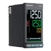
gefran 650 Series Installation And Instruction Manual (183 pages)
PID temperature controllers
Brand:
gefran
| Category:
Controller
| Size: 10.61 MB
Table of Contents
Display and Keys
17
General Installation Rules
21
Minimum Space for Ventilation
22
General Rules for Connections
23
CT Inputs
31
Display Characters
35
Fast Configuration
37
Passwords
45
IN.SPR - Remote Setpoint Input Available
50
HBB - Enable Hold Back Band Function
59
ENBL.1 - Consent 1 to Execute Step
61
ENBL.3 - Consent 3 to Execute Step
62
EVN.R.4 - Event 3 During Step Ramp
63
GROP.R - Group of Parameters Assigned to Ramp
64
I.MAIN Submenu - Configuration of Main Input
65
Type - Selecting Sensor Type
66
Lin - Selecting Linearization Type
67
Unit - Selecting the Displayed Unit of Measurement
68
LO.SCL - Lower Limit of Scale
69
OF.SCL - Scale Offset Correction
70
I.SPR Submenu - Configuration of Remote Setpoint Input
71
T.spr - Selecting Type of Remote Setpoint Input
72
LO.SPR - Minimum Scale Limit
73
I.CT1 Submenu - Configuration of Current Transformer CT1
74
FILT.1 - Digital Filter
75
4.10. I.CT2 Submenu - Configuration of Current Transformer CT2
76
FILT.2 - Digital Filter
77
ALARM Submenu - Configuration of Alarms
78
ALARM - Selecting the Alarm to be Configured
79
N.s.X - Method for Applying Hysteresis
80
HYSTE - Hysteresis
81
AL.HB Submenu – Configuring the Heater Break Alarm
82
LOW.ON - Alarm Due to Insufficient Current Draw
83
THR.PE - Percentage of HB Current Compared to Calibration
84
BLK.HB - Flashing of PV Display
85
PID Submenu – Configuring Control Parameters
86
S.TUNE - Enabling Self-Tuning
87
Aut.t - Selecting Type of Auto-Tuning
88
H.PB - Proportional Heating Band or Hysteresis in on off Control
89
COOL - Selecting Cooling Fluid
90
C.P.HI - Maximum Limit of Cooling Power
91
FEEDF - Feedforward Power
92
Unit - Unit of Measurement of Gradient
93
PID.GR Submenu – Configuring Groups of Control Parameters
94
PID.G.R - Selecting the Parameter Group to be Confi Gured
95
H.P.LO - Minimum Limit of Heating Power
96
C.P.LO - Minimum Limit of Cooling Power
97
I.DIGT Submenu – Configuring Digital Inputs
98
I.DIG.N - Selecting the Digital Input
99
ST.EN.N - Setting Assigned Consent Number
100
OUTPU Submenu – Configuring Outputs
101
OUT.N - Selecting the Output
102
F.ou.X - Selecting the Function Assigned to Relay, Logic or Triac Output
103
EVNT.N - Setting the Event Number
104
MSG.OU - Selecting the Output Message
105
Output
106
S.o.a1 - Defining the State of the Analog Output
107
HI.A1 - Scale Maximum
108
VALVE Submenu – Configuring Valve Parameters
109
F.ual - Defining Valve Function
110
TIM.ON - Minimum Valve Impulse Time or on Time in Impulse Mode
111
MODE Submenu – Configuring Functioning Mode
112
PID.G.N - Number of Groups of Control Parameters
113
On.of - Enabling Software On/Off
114
Tmer - Enabling Timer Function
115
T.pro - Setting the Programmer Base Time
116
TIMER Submenu – Configuring Timer Parameters
117
F.tim - Selecting Timer Function Mode
118
Res.t - Defining the Timer Reset Command Logic
119
MSG.TM - Selecting the Message Assigned to the Active Count
120
4.21. ENERG Submenu - Configuring Energy Counter Parameters
121
V.LINE - Nominal Line Voltage
122
SERIA Submenu – Configuring Serial Communication
123
CODE - Identification Code
124
HMI Submenu – Configuring the Display and Keypad
125
But.1 - Selecting Function Key 1
126
Ds.sp - Selecting the SV Display
127
MSG.LO - Selecting the Message Assigned to Low
128
MSG.SB - Selecting the Message Assigned to Sbr
129
QUICK - Quick Configuration Menu
130
LINRZ Submenu – Configuring Custom Linearization
131
Stp.XX - Value of Step XX
132
US.CAL Submenu – User Calibrations
133
U.CAL - Selecting the User Calibration
134
RTD.LO - Calibrating Minimum Resistance Value
135
Day - Setting Day of Week
136
C.HIG - Setting Analog Output Maximum
137
PASC1 - Setting Level 1 Password 1
138
Heat/Cool Control Application
139
Heating Control and Current (CT) Application
141
5.2.2. Quick Configuration Procedure for Model 650-D-R00
142
Remote Setpoint Input
143
Alarms
144
HB Alarm
145
Retransmission Output
146
Self-Tuning
147
Auto-Tuning
148
Timer
149
Stabilization Timer
150
Multiset, Setpoint Gradient
151
Programmer Behavior
152
Cyclical Program with 3 Setpoints and 3 Steps
154
Managing Motorized Valves
155
Energy Counter
156
Logic Operations
157
Programming Function Block
158
Enabling the Function Block and Selecting the Type of Fun Ctional Logic
159
Configuring the Output
160
Programming with Pc
161
Operator Guide
163
Operation as Programmer
164
Configuration (User Menu)
165
Maintenance
167
Disposal
168
Technical Data
169
Order Methods
176
Controller
177
Controller
178
Accessories
180
Advertisement
gefran 650 Series Abbreviated Manual (78 pages)
Brand:
gefran
| Category:
Temperature Controller
| Size: 5.71 MB
Table of Contents
Table of Contents
2
Excerpts from Controller Manual
4
3 Commissioning
4
Information on Displays and Use of Keys
4
Navigating the Menus
4
Displays
4
Display Characters
4
Scrolling Messages
5
Sequence at Power-On
5
First Power-On
6
Fast Configuration
6
Setting up Quick Configuration
10
Setting up the Alarm
10
Setting up the Heater Break Alarm
11
Setting up the PID
12
4 Configuration
14
Programming/Configuration Menu
14
First: Know What You're Doing
14
Passwords
14
Main Menu
15
Legend for Submenus and Parameters
16
Submenu
16
Parameters
16
INFO Submenu - Information Display
17
SW.VER - Versione Software
18
CODE - Identifying Code of Controller
18
ERROR - Main Input Error
18
SAP.C - SAP Code
18
Ser.n - Serial Number of Controller
18
Model of Controller
19
Type of Controller
19
L.FUNC - Option Logic Functions Available
19
IN.SPR - Remote Setpoint Input Available
19
OUT.A1 - Analog Output 1 Available
19
Ctx - Current Transformer Input Available
20
X.in.dg - Digital Input Available
20
RS485 - RS485 Serial Port Available
20
Out2 - Type of Output 2
20
Out3 - Type of Output 3
21
Out4 - Type of Output 4
21
OUT1.S - Number of Switchings Output 1
21
OUT2.S - Number of Switchings Output 2
21
OUT3.S - Number of Switchings Output 3
21
OUT4.S - Number of Switchings Output 3
22
T.DAYS - Total Working Days
22
P.DAYS - Partial Working Days
22
T.INT - Internal Temperature of Controller
22
T.MIN - Minimum Internal Temperature of the Controller
22
T.MAX - Maximum Internal Temperature of the Controller
23
Time - Internal Time
23
Date - Internal Date
23
PR.OPT - Selecting Program
25
FI.STP - Number of First Step Assigned to Program
25
LA.STP - Number of Last Step Assigned to Program
25
Strt - Restart Mode
25
RST.SP - Type of Control after Program Restart
25
WAIT.S - Option to Start Execution of Program
26
End - Action at End of Program
26
LIMIT - Limitation of Step Duration
26
PR.STP Submenu - Configuration of Program Steps
26
PR.STP Programming Step
27
SETP - Programming Step Setpoint
28
RAMP.T - Step Time Ramp
28
HOLD.T - Hold Time in Step
28
HBB - Enable Hold Back Band Function
28
BAND - Maximum Deviation for HBB
29
HBB.R - Enabling HBB During Ramp
29
HBB.H - Enabling HBB During Hold
29
HBB2 - Enabling HBB with Respect to I.SPR
29
S.SP.EN - Enabling Retransmission of Setpoint
29
SUB.SP - Setpoint Value of Slaved Controller
30
S.RM.EN - Enabling Ramp for Slaved Controller
30
ENBL.1 - Consent 1 to Execute Step
30
ENBL.2 - Consent 2 to Execute Step
30
ENBL.3 - Consent 3 to Execute Step
31
ENBL.4 - Consent 4 to Execute Step
31
EVN.R.1 - Event 1 During Step Ramp
31
EVN.R.2 - Event 2 During Step Ramp
31
EVN.R.3 - Event 3 During Step Ramp
31
EVN.R.4 - Event 3 During Step Ramp
32
EVN.H.1 - Event 1 During Step Hold
32
EVN.H.2 - Event 2 During Step Hold
32
EVN.H.3 - Event 3 During Step Hold
32
EVN.H.4 - Event 4 During Step Hold
32
GROP.R - Group of Parameters Assigned to Ramp
33
GROP.H - Group of Parameters Assigned to Hold
33
MSG.R - Message Associated with the Ramp
33
MSG.H - Message Associated with the Maintenance
33
I.MAIN Submenu - Configuration of Main Input
34
Type - Selecting Sensor Type
35
Lin - Selecting Linearization Type
36
Unit - Selecting the Displayed Unit of Measurement
37
FILT - Digital Filter
37
FILT.D - Digital Filter on PV Display
37
DEC.P - Number of Decimals Displayed
37
LO.SCL - Lower Limit of Scale
38
HI.SCL - Upper Limit of Scale
38
ALARM Submenu - Configuration of Alarms
39
ALARM - Selecting the Alarm to be Configured
40
Ref.X - Selecting the Alarm Reference
40
Selecting Direct or Inverse Alarm
40
Selecting Absolute or Deviation Alarm
40
Method for Applying Hysteresis
41
PWON.E - Disabling the Alarm at Power-On
41
LATCH - Memorizing the Alarm
41
HYSTE - Hysteresis
42
DELAY - Alarm Trip Delay
42
MSG.AL - Message Associated with Tripping of Alarm
42
BLK.AL - Flashing of PV Display
42
PID Submenu - Configuring Control Parameters
43
S.TUNE - Enabling Self-Tuning
44
SOFT.S - Enabling Soft-Start
44
SOFT.T - Soft-Start Time
44
A.TUNE - Enabling Auto-Tuning
44
Aut.t - Selecting Type of Auto-Tuning
45
Cntr - Selecting Type of Control
45
MODE Submenu - Configuring Functioning Mode
46
PID.G.N - Number of Groups of Control Parameters
47
MA.AU - Defining Transition from Manual to Automatic
47
AU.MA - Defining Transition from Automatic to Manual
47
Lo.re - Defining Transition from Remote SP to Local SP
47
On.of - Enabling Software On/Off
48
MA.P.L - Enabling Manual Power Latch
48
Man.p - Enabling Change of Manual Power Value
48
Dig - Defining Type of Digital Inputs
48
ALRM.N - Number of Alarms Enabled
48
Tmer - Enabling Timer Function
49
MUL.SP - Enabling Multiset Function
49
SP.REM - Enabling the Remote Setpoint
49
Spr.t - Defining Absolute or Deviation Remote Setpoint
49
PROGR - Enabling the Setpoint Programmer
49
T.pro - Setting the Programmer Base Time
50
ENERG - Enabling the Energy Counter Function
50
T.SAMP - Main Input Sample Time
50
FREQZ - Defining Power Line Frequency
50
TIMER Submenu - Configuring Timer Parameters
51
F.tim - Selecting Timer Function Mode
52
St.st - Selecting the Start/Stop Timer Command
52
Defining the Start/Stop Timer Command Logic
52
Rese - Selecting the Reset Timer Command
52
Res.t - Defining the Timer Reset Command Logic
53
BAND - Band for Timer Count
53
End - Selecting the Function Activated at End of Count
53
TIMER - Timer Value
53
MSG.TM - Selecting the Message Assigned to the Active Count
54
SERIA Submenu - Configuring Serial Communication
55
CODE - Identification Code
56
KBAUD - Selecting Communication Speed
56
Par - Selecting Parity
56
HMI Submenu - Configuring the Display and Keypad
57
But.1 - Selecting Function Key 1
58
But.2 - Selecting Function Key 2
58
Ds.sp - Selecting the SV Display
59
Ds.f - Selecting the F Display
59
Barg - Selecting the Bargraph Display
59
MSG.LO - Selecting the Message Assigned to Low
60
MSG.HI - Selecting the Message Assigned to HIGH
60
MSG.ER - Selecting the Message Assigned to Err
60
MSG.SB - Selecting the Message Assigned to Sbr
61
Lang - Selecting Language for Messages
61
SPEED - Message Scrolling Speed
61
BACKL - Backlighting Level
61
QUICK - Quick Configuration Menu
62
US.CAL Submenu - User Calibrations
63
U.CAL - Selecting the User Calibration
64
FI.CAL - Resetting the Factory Calibration
64
C.LOW - Calibrating Minimum Current / Voltage
64
C.HIGH - Calibrating Maximum Current / Voltage
64
RTD.LO - Calibrating Minimum Resistance Value
65
RTD.HI - Calibrating Maximum Resistance Value
65
HOUR - Setting Hours
65
MIN - Setting Minutes
65
SEC - Setting Seconds
65
Day - Setting Day of Week
66
DATE - Setting Day
66
Mont - Setting Month
66
YEAR - Setting Year
66
C.LO - Setting Analog Output Minimum
66
C.HIG - Setting Analog Output Maximum
67
PASC1 - Setting Level 1 Password 1
68
PASC2 - Setting Level 2 Password 2
68
FI.CFG - Entering the Reset Code
68
Alarms
69
Generic Alarms AL1
69
How to Switch It off
70
How to Switch It on
70
Soft-Start
70
Tuning
70
Tuning Actions
70
Influence of Proportional, Derivative and Integral Actions on Response of Controlled Process
70
Manual Tuning
70
Self-Tuning
71
Auto-Tuning
72
Examples of Tuning
72
Timer
73
Start/Stop Timer
73
Stabilization Timer
74
Start Timer
74
Variables Available for the User Configuration Menu
74
What Is a Program
75
Programmer Functions
75
Programmer Behavior
76
Program Examples
76
ONE STEP Program
76
Program with Assigned Events
76
Cyclical Program with 3 Setpoints and 3 Steps
78
Program with HBB (Hold Back Band) Function
78
Fast Simulation of Program
78
Controlling the Program from the
78
Keypad
78
Programmer Reset Mode
78
Restart with Step Search
78
gefran 650 Series Manual (27 pages)
1/16 & 1/8 DIN PID TEMPERATURE CONTROLLERS
Brand:
gefran
| Category:
Temperature Controller
| Size: 1.26 MB
Advertisement
gefran 650 Series Manual (16 pages)
PID TEMPERATURE CONTROLLERS
Brand:
gefran
| Category:
Controller
| Size: 5.63 MB
Table of Contents
Preventive Maintenance
2
Easy Setup
6
Setpoint Programmer
8
Main Input
10
Advertisement
Related Products
gefran 600
gefran GFW-Xtra 60
gefran 650 L
gefran G-Vision 66-070
gefran G-Vision 66-101
gefran G-Vision 66-156
gefran G-Vision 66-215
gefran G-Vision 67-070
gefran G-Vision 67-101
gefran G-Vision 67-156
gefran Categories
Controller
Control Unit
Relays
Inverter
Measuring Instruments
More gefran Manuals
Login
Sign In
OR
Sign in with Facebook
Sign in with Google
Upload manual
Upload from disk
Upload from URL