
Related Manuals for gefran 650


Summary of Contents for gefran 650
- Page 1 650 - 1250 - 1350 PID temperature controllers INSTALLATION AND INSTRUCTION MANUAL code:80208G...
- Page 3 T.MIN - Minimum internal temperature of the controller 2.2.4. Power supply .............21 2.2.5. Connecting inputs and outputs .........22 4.4.26. T.MAX - Maximum internal temperature of the control- 2.3. 650 connection diagrams .............23 ler ................52 2.3.1. General diagram............23 4.4.27. tiME - Internal time .............52 2.3.2. Power supply .............24 4.4.28.
- Page 4 CONTENTS 4.6.13. ENBL.1 - Consent 1 to execute step ......59 4.13.2. SOFT.S - Enabling Soft-Start ........85 4.6.14. ENBL.2 - Consent 2 to execute step ......59 4.13.3. SOFT.T - Soft-Start Time ...........85 4.6.15. ENBL.3 - Consent 3 to execute step ......60 4.13.4.
- Page 5 Heat/cool control application ..........137 5.1.1. Connection diagram..........137 4.19.14. PROGR - Enabling the setpoint programmer ..113 5.1.2. Quick configuration procedure for model 650–D-R00- 4.19.15. t.Pro - Setting the programmer base time ....114 00000-1 ..............138 4.19.16. ENERG - Enabling the energy counter function..114 5.2.
- Page 6 Replacing the controller .............165 8.2. Replacing the gasket............165 8.3. Cloning the configuration ...........165 8.4. Cleaning ................165 8.5. Disposal ................166 8.6. Troubleshooting ..............166 Technical data ............Order methods ............10.1. 650 Controller ..............174 10.2. 1250 Controller ..............175 10.3. 1350 Controller ..............176 Accessories ............80208G_MHW_650-1250-1350_01-2017_ENG...
- Page 7 CONTENTS 80208G_MHW_650-1250-1350_01-2017_ENG...
- Page 8 CONTENTS 80208G_MHW_650-1250-1350_01-2017_ENG...
- Page 9 In the space below, write the order code and other plate data shown on the label attached to the outside of the controller (see figure). If you need technical assistance, this information must be given to Gefran Customer Service. Serial...
- Page 10 MUST be followed. Indicates a reference to other technical documents Indicates risk for the safety of the installer or user that can be downloaded from www.gefran.com. due to the presence of high voltage. Indicates a point to which the reader’s attention is called.
- Page 11 They may be the result of test conditions at Gefran S.p.A., and the user must compare them to his/her real application Gefran S.p.A. also reserves the right to change the contents requirements.
- Page 12 INTRODUCTION 80208G_MHW_650-1250-1350_01-2017_ENG...
- Page 13 1.1. Profile 1250 1350 The 650, 1250 and 1350 controllers are a family of devices The initial parameters can always be reset, both from the designed to control temperature in industrial processes and keypad and from the GF_eXpress software. to manage the positioning (without feedback) of motorized valves.
- Page 14 1. GENERAL DESCRIPTION 1.2. Differences among models 1250 1350 Display dimensions 35 × 30 mm 37 × 68 mm 83 × 68 mm PV display 4 digit, 7 seg., H = 17 mm 4 digit, 7 seg., H = 17 mm 4 digit, 7 seg., H = 23 mm SV display 5 digit, 14 seg., H = 7 mm...
- Page 15 Up/down keys: raise/lower the value of the parameter displayed on the SV or PV display. F key: lets you navigate among controller menus and Figure 1 - Description of 650 display and keys parameters. Confirms the parameter value and selects the next parameter.
- Page 16 1. GENERAL DESCRIPTION 1.3.2. Drilling dimensions and templates 2.76 2.28 1.89 +0.6 - 0.0 1.78 Figure 2 - 650 drilling dimensions and templates 80208G_MHW_650-1250-1350_01-2017_ENG...
-
Page 17: Display And Keys
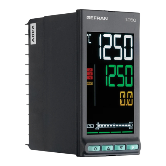
1. GENERAL DESCRIPTION 1.4. 1250 Controller Main features • Operator interface with large LCD Display, customi- zable, with choice of colors • Scrolling diagnostics messages, configurable, in the se- lected language • Easy, guided configuration, copy/paste parameters even with power off •... - Page 18 1. GENERAL DESCRIPTION 1.4.2. Drilling dimensions and templates 1.89 2.76 + 0.6 - 0.0 1.78 Figure 4 - 1250 drilling dimensions and templates 80208G_MHW_650-1250-1350_01-2017_ENG...
- Page 19 1. GENERAL DESCRIPTION 1.5. 1350 Controller Main features • Operator interface with large LCD Display, customi- zable, with choice of colors • Scrolling diagnostics messages, configurable, in the se- lected language • Easy, guided configuration, copy/paste parameters even with power off •...
- Page 20 1. GENERAL DESCRIPTION 1.5.2. Drilling dimensions and templates 3.78 4.53 + 0.8 - 0.0 3.64 Figure 6 - 1350 drilling dimensions and templates 80208G_MHW_650-1250-1350_01-2017_ENG...
-
Page 21: General Installation Rules
See Chapter 10 - Ordering code - to check the configuration corresponding to each order code. Attention! If even one of the requirements mentioned above (trained technician in, device in perfect condition, correct configuration) is not satisfied, interrupt the installation and contact your Gefran dealer or Gefran Customer Service. 2.1. -
Page 22: Minimum Space For Ventilation
2.1.6. Positioning Figure 8 - Fastening the 650 The controller must be positioned so that the display is not subject to direct sunlight or to very strong sources of light. If necessary, filter direct light, for example, with a reflective screen. -
Page 23: General Rules For Connections
2. INSTALLATION 2.2. Connections Attention! Failure to follow the instructions in this Cable / terminal Cable / terminal Terminal size section may cause problems in electrical safety and section electromagnetic compatibility, in addition to voiding Rigid cable 0,2...2,5 mm the warranty. (24...14 AWG) 2.2.1. - Page 24 2. INSTALLATION Attention! Make sure the ground connection is effi- Attention! If the controller is connected to devices cient. Absent or inefficient grounding can make the that are NOT electrically isolated (such as ther- device unstable due to excessive noise. mocouples), ground with a specific conductor to Specifically, check that: prevent grounding directly through the machine...
- Page 25 2. INSTALLATION 2.3. 650 connection diagrams 2.3.1. General diagram OUT 2 OUT 2 OUT 1 (main) OUT 3 OUT 4 5 V, 10 V OUT 3 OPTIONS B (Data +) IN 2 A (Data -) RS485 IN 1 IN 1...
- Page 26 2. INSTALLATION 2.3.2. Power supply Input PT100/JPT100 - 3-wires connection Attention: Power supply with this type of connection the line resistance can introduce me- asurement error, we recommend that you use wires of adequate Standard: 100...240 VAC/VDC ±10% screen. 50/60Hz, max 5 VA The resistance of the three wires must be equal, the line resistance Optional: 20...27 VAC/VDC ±10%...
- Page 27 2. INSTALLATION Output Out 2 – logic Option 1 Logic 24 V Digital inputs NPN 24 V, 4,5 mA (10 V to 20 mA) Current transformer 50 mA, 10 , 50/60 Hz Second current transformer for 2-phase / 3-phase load Output Out 3 –...
- Page 28 2. INSTALLATION Option 5 Option 3 + SPR B (Data +) Remote Setpoint Serial line 0...10 V, R > 30 kΩ RS485 2-wires A (Data -) 0...20 mA, 4...20 mA, R = 50 Ω +12/24 V max 3,6 mA Digital inputs PNP digital inputs NPN 24 V, 4,5 mA Option 5...
- Page 29 2. INSTALLATION 2.4. 1250 - 1350 connection diagrams 2.4.1. General diagram OUT 4 OUT 3 IN 5 OUT 2 IN 4 IN 3 OUT 1 (main) IN 2 IN 1 5 V, 10 V B (Data +) A (Data -) SPR + SPR - LEGEND...
- Page 30 2. INSTALLATION 2.4.2. Power supply Input PT100/JPT100 - 3-wires connection Powe supply Attention: with this type of connection the line resistance can introduce me- Standard: 100...240VAC/DC ± 10% asurement error, we recommend 50/60Hz, max 10VA that you use wires of adequate screen.
-
Page 31: Ct Inputs
2. INSTALLATION Digital inputs Output Out 2 - logic Digital inputs Logic 24 V NPN 24 V, 4,5 mA (10 V to 20 mA) Digital inputs Output Out 3 - 5 A relay 5 A relay 250 VAC / 30 VDC PNP digital inputs +12/24 V max 3,6 mA Output Out 4 –... - Page 32 2. INSTALLATION 2.4.8. Remote setpoint input Remote setpoint input Remote setpoint 0...10 V, Ri > 30 kΩ SPR - 0...20, 4...20 mA, Ri = 50 Ω 2.4.9. Analog output Analog output Analog output 0...10 V, max 20 mA Out A1 0...20 mA, 4...20 mA, Rout <...
- Page 33 Frame ground (FG) (*) f or model 1/2 W 650-x-xxx-00031-x 650-x-xxx-00101-x No. 1 No. 31 650-x-xxx-00201-x Figure 13 - RS485 connection for 650 controller Host computer RS485 Shield B (+) A (-) Frame ground (FG) 1/2 W 1250 - 1350 1250 - 1350 No.
- Page 34 2. INSTALLATION 80208G_MHW_650-1250-1350_01-2017_ENG...
-
Page 35: Display Characters
“1.3.1. Display and keys” on page The controllers have 2 or 3 displays, depending on the model. 13 for the 650, “1.4.1. Display and keys” on page 15 for the The Main menu shows: 1250, and “1.5.1. Display and keys” on page 17 for the 1350. - Page 36 3. COMMISSIONING 3.1.2.2. Scrolling messages “ & ‘ The SV (650) and F (1250 and 1350) displays can show scrol- ling alphameric messages. These messages, up to 32 cha- racters in length, appear: • during configuration, describing the active parameter; •...
-
Page 37: Fast Configuration
3. COMMISSIONING 3.3. First power-on At first power-on, after the controller has run the self-diagnostics test, press the key to access the Fast Configuration Menu. The parameters shown are a subset of all the controller parameters and let you rapidly configure the inputs and outputs. - Page 38 3. COMMISSIONING Home Selecting output 1 function The proposed functions depend on output type (relay, logic). > 2 s Selecting output 2 function The proposed functions depend on output type (relay, logic). > 2 s Selecting output 3 function The menu item appears only if the optional output is availableis available.
- Page 39 3. COMMISSIONING Home Raises the value Full-scale value of current transformer CT1 The menu item appears only if the optional input is available Lowers the value > 2 s Full-scale value of current transformer CT2 Raises the value The menu item appears only if the optional input is available Lowers the value >...
- Page 40 3. COMMISSIONING Home Selecting digital input 5 function The menu item appears only if the optional input is available (for models 1250 and 1350 only). > 2 s Raises the value Setting Setpoint Lowers the value > 2 s Raises the value Setting Alarm 1 Lowers the value >...
- Page 41 3. COMMISSIONING 3.4. Setting up quick configuration The quick configuration menu lets you quickly configure You can set up the first configuration with the main confi- and start a controller. guration menu (see paragraph “4.1 Programming/Configu- ration Menu” on page 43), which gives access to all of the To do this, it uses default values for many of the parameters parameters.
- Page 42 3. COMMISSIONING 3.4.2. Setting up the Heater Break Alarm If at least one output was configured as Heater Break Alarm in the fast configuration. 0000 Home page 0000 Press > 2 seconds Enter password (default = 1) with the keys PASS1 Press 4 times (if the model does not have remote setpoint input and current transformer options and is not the Programmer)
- Page 43 3. COMMISSIONING 3.4.3. Setting up the PID 0000 Home page 0000 Press > 2 seconds Enter password (default = 1) with the keys PASS1 Press 5 times (if the model does not have remote setpoint input and current transformer options and is not the Programmer) Submenu Enable or disable Self-Tuning (default = OFF) with the keys...
- Page 44 3. COMMISSIONING • set the LBA alarm trip delay LBA (parameter LBA.TM, default = 30.0); • set the value of power delivered when the LBA alarm trips (parameter LBA.PW, default = 25.0). 80208G_MHW_650-1250-1350_01-2017_ENG...
-
Page 45: Passwords
• Password 2 = 2 In case of doubts, or if you need any explanations, please consult www.gefran.com or contact Gefran The passwords can be changed and even disabled if you Customer Care. want. See paragraphs “4.27. Submenu PASC1 - Setting level 1 password”... - Page 46 4. CONFIGURATION 4.2. Main menu > 6 s Home 0000 Submenu Submenu 0000 > 2 s pag. pag. Insert password 2 Insert password 1 PASS1 PASS2 Pag. User configuration menu If password is correct, enter menu, If password is correct, enter menu, (max 50 parameters) if not, Home if not, Home...
- Page 47 4. CONFIGURATION 4.3. Legend for submenus and parameters The purposes and characteristics of submenus and parameters are described and summarized in the following tables. 4.3.1. Submenu Acronym Scrolling message Password Description INFO INSTRUMENT STATUS Level 1 Gives information on controller state and HW configuration Acronym of submenu as it appears on controller di- splay.
- Page 48 Type of output 1 * SEr.n Out1 of controller days P.DAYS Internal Type of output 2 * Model of Out2 temperature 650.LV controller T.INT of controller Minimum internal Type of Type of output 3 * Out3 temperature of the controller CONTR T.MIN...
- Page 49 4. CONFIGURATION 4.4.1. SW.VER - Versione software Acronym Scrolling message Password Description SW.VER SOFTWARE VERSION INFO The parameter shows the version (major.minor) of the controller software. Unit of measurement: - Options: 4.4.2. CODE - Identifying code of controller Acronym Scrolling message Password Description CODE...
-
Page 50: In.spr - Remote Setpoint Input Available
(650LV, 650HV, 1250LV, 1250HV, 1350LV, 1350HV). Unit of measurement: Options: 650.LV = 650 controller powered at 20...27 VAC/VDC 650.HV = 650 controller powered at 100...240 VAC/VDC 125.LV = 1250 controller powered at 20...27 VAC/VDC 125.HV = 1250 controller powered at 100...240 VAC/VDC 135.LV = 1350 controller powered at 20...27 VAC/VDC... - Page 51 4. CONFIGURATION 4.4.11. CTx - Current transformer input available Acronym Scrolling message Submenu Attributes CURRENT TRASFORMER AVAILABLE INFO If present, the parameter indicates that one or more current transformer inputs are installed on the controller. Unit of measurement: Options: = The device has 1 current transformer input CT1+2 = The device has 2 current transformer inputs 4.4.12.
- Page 52 If present, the parameter indicates that output 3 is available on the controller and specifies the type. Unit of measurement: Options: RELAY = Relay output TRIAC = Triac output (only for 650 model) 4.4.17. Out4 - Type of output 4 Acronym Scrolling message...
- Page 53 4. CONFIGURATION 4.4.21. OUT4.S - Number of switchings output 3 Acronym Scrolling message Submenu Attributes OUT4.S NUMBER X 1000 RELAY CYCLES INFO If output 4 is available on the controller, the parameter shows the number of switchings (in thousands). Unit of measurement: Number (×...
- Page 54 4. CONFIGURATION 4.4.26. T.MAX - Maximum internal temperature of the controller Acronym Scrolling message Submenu Attributes T.MAX MAX INTERNAL TEMPERATURE INFO The parameter shows the maximum internal temperature of the controller measured during work. Unit of measurement: °C Options: 4.4.27. tiME - Internal time Acronym Scrolling message Submenu...
- Page 55 4. CONFIGURATION 4.5. PR.OPT Submenu - Configuring programs Acronym Scrolling message Password Description PR.OPT PROGRAMMER Levelo Lets you configure the 4 programs manageable by the pro- CONFIGURATION grammer. The parameters are configured for each program to be used. The Programmer function must first be enabled with the menu MODE, parameter PROGR = On.
- Page 56 4. CONFIGURATION 4.5.1. PR.OPT - Selecting program Acronym Scrolling message Submenu Attributes PR.OPT PROGRAM NUMBER PR.OPT The parameter lets you select the program to be configured. During normal functioning, the controller shows the number of the program running and its state P.STAT, viewable in the User Configuration menu. Unit of measurement: Number Options:...
- Page 57 4. CONFIGURATION 4.5.6. WAIT.S - Option to start execution of program Acronym Scrolling message Submenu Attributes WAIT.S DEF OF START EXEC PROGRAM PR.OPT Il parametro abilita o disabilita l’esecuzione automatica del reset della base tempi del programma dopo una commutazio- ne STOP/START.
- Page 58 4. CONFIGURATION Submenu PR.STP - Configuration of program steps Parameter Page Parameter Page Parameter Page Setpoint value Event 1 during Programming step of slaved controller step hold PR.STP SUB.SP EVN.H.1 Enabling ramp Event 2 during Programming step for slaved con- step hold setpoint SETP...
-
Page 59: Hbb - Enable Hold Back Band Function
4. CONFIGURATION 4.6.1. PR.STP - Programming step Acronym Scrolling message Submenu Attributes PR.STP PROGRAMMER ACTUAL STEP PR.SPT The parameter shows and sets the number of the programming step being configured. Unit of measurement: Step number Options: 1...12 4.6.2. SETP - Programming step setpoint Acronym Scrolling message Submenu... - Page 60 4. CONFIGURATION 4.6.6. BAND - Maximum deviation for HBB Acronym Scrolling message Submenu Attributes BAND HOLD BACK BAND VALUE PR.SPT If the HBB function is enabled, the parameter shows and sets the maximum deviation allowed for PV compared to SV. Unit of measurement: °C, °F, % based on chosen scale Options:...
-
Page 61: Enbl.1 - Consent 1 To Execute Step
4. CONFIGURATION 4.6.11. SUB.SP - Setpoint value of slaved controller Acronym Scrolling message Submenu Attributes SUB.SP SUBDUED SETPOINT ASSOCIATED TO STEP PR.SPT If the S.SP.EN function is enabled, the parameter shows and sets the setpoint value to be retransmitted as a percentage of the controller setpoint value EXAMPLE If the setpoint of the main controller is 180°C and you want the setpoint of the secondary controller to be... -
Page 62: Enbl.3 - Consent 3 To Execute Step
4. CONFIGURATION 4.6.15. ENBL.3 - Consent 3 to execute step Acronym Scrolling message Submenu Attributes ENBL.3 STEP ENABLE FOR STEP START PR.SPT The parameter shows and sets consent 3 condition to enable execution of the step. See ENBL.1 for details. 4.6.16. -
Page 63: Evn.r.4 - Event 3 During Step Ramp
4. CONFIGURATION 4.6.20. EVN.R.4 - Event 3 during step ramp Acronym Scrolling message Submenu Attributes EVN.R.4 EVENT DURING STEP RAMP PR.SPT The parameter shows and sets the configuration of event 4 during the step ramp.. Unit of measurement: Options: nonE = Event not modified = Event becomes active = Event becomes inactive... -
Page 64: Grop.r - Group Of Parameters Assigned To Ramp
4. CONFIGURATION 4.6.25. GROP.R - Group of parameters assigned to ramp Acronym Scrolling message Submenu Attributes GROP.R CONTROL PARAMETER GROUP DURING STEP RAMP PR.SPT The parameter shows and sets the group of control parameters assigned to the step during the ramp. PID.G.N is settable on the MODE submenu. -
Page 65: I.main Submenu - Configuration Of Main Input
4. CONFIGURATION 4.7. I.MAIN Submenu - Configuration of main input Acronym Scrolling message Password Description I.MAIN MAIN INPUT CONFIG Level 1 Lets you configure the controller’s main input. Parameter Parameter page page tyPE Selecting Lower limit for sensor type setpoint LO.SP Selecting Upper limit for... -
Page 66: Type - Selecting Sensor Type
4. CONFIGURATION 4.7.1. tyPE - Selecting sensor type Acronym Scrolling message Submenu Attributes tyPE MAIN INPUT TYPE OF PROBE I.MAIN The parameter shows and sets the sensor type of the main input. The functions for calibrating Custom sensors are on the US.CAL menu. When a 4...20 mA input is used and the current is less than 2 mA, an Err message is generated and the relay state speci- fied with the FAUL.T parameters is activated. -
Page 67: Lin - Selecting Linearization Type
4. CONFIGURATION Unit of measurement: Options: J.TC = J thermocouple K.TC = K thermocouple R TC = R thermocouple S TC = S thermocouple T.TC = T thermocouple C.TC = C thermocouple D.TC = D thermocouple PT2.TC = Pt20Rh / Pt40Rh thermocouple INFR1 = IR sensor type 1 INFR2... -
Page 68: Unit - Selecting The Displayed Unit Of Measurement
4. CONFIGURATION 4.7.3. Unit - Selecting the displayed unit of measurement Acronym Scrolling message Submenu Attributes Unit UNIT OF MEASURE I.MAIN The parameter shows and sets the unit of measurement displayed for input 1. The unit appears on the Home page of the display. -
Page 69: Lo.scl - Lower Limit Of Scale
4. CONFIGURATION 4.7.7. LO.SCL - Lower limit of scale Acronym Scrolling message Submenu Attributes LO.SCL INPUT LOW LIMIT I.MAIN The parameter shows and sets the lower limit of the measurement scale used for the main input, based on input (or sen- sor) type, unit of measurement, and number of decimals selected. -
Page 70: Of.scl - Scale Offset Correction
4. CONFIGURATION 4.7.9. OF.SCL - Scale offset correction Acronym Scrolling message Submenu Attributes OF.SCL INPUT OFFSET I.MAIN The parameter shows and sets the offset applied to the value read in input to make it correspond to the expected value for a certain temperature. It corrects any constant read error of the sensor. This offset is applied linearly to all reads;... -
Page 71: I.spr Submenu - Configuration Of Remote Setpoint Input
4. CONFIGURATION 4.8. I.SPR Submenu - Configuration of remote setpoint input Acronym Scrolling message Password Description I.SPR REMOTE SETPOINT Level 1 Lets you configure the remote setpoint input if it is installed INPUT CONFIG on the controller. The remote setpoint can be assigned to the process variable PV (active in REM mode) or to the POWER value (active in MAN + REM mode). -
Page 72: T.spr - Selecting Type Of Remote Setpoint Input
4. CONFIGURATION 4.8.1. t.SPr - Selecting type of remote setpoint input Acronym Scrolling message Submenu Attributes t.SPr DEFINITION OF REMOTE SETPOINT I.SPR The parameter shows and sets the type of remote setpoint input. Unit of measurement: Options: 20MA = Current input in 0...20 mA 4-20M = Current input in 4...20 mA = Voltage input in 0...10 V... -
Page 73: Lo.spr - Minimum Scale Limit
4. CONFIGURATION 4.8.5. LO.SPR - Minimum scale limit Acronym Scrolling message Submenu Attributes LO.SPR INPUT LOW LIMIT I.SPR The parameter shows and sets the minimum scale limit. Unit of measurement: Scale points or %, according to the remote setpoint input function selected Options: -1999...9999 = In scale points referred to main input -199.9...999.9 = In %, if the Power or RST.PW function was selected... -
Page 74: I.ct1 Submenu - Configuration Of Current Transformer Ct1
4. CONFIGURATION 4.9. I.CT1 Submenu - Configuration of current transformer CT1 Acronym Scrolling message Password Description I.CT1 CURRENT Level 1 Lets you configure the input for current transformer CT1. TRASFORMER 1 INPUT CONFIG Parameter page Digital filter FILT.1 Maximum scale HI.CT1 limit Scale offset... -
Page 75: Filt.1 - Digital Filter
4. CONFIGURATION 4.9.1. FILT.1 - Digital filter Acronym Scrolling message Submenu Attributes FILT.1 DIGITAL FILTER I.CT1 The parameter shows and sets the value of the digital filter time constant applied to the input for current transformer CT1. Unit of measurement: Seconds Options: 0.00...20.00... -
Page 76: 4.10. I.ct2 Submenu - Configuration Of Current Transformer Ct2
4. CONFIGURATION 4.10. I.CT2 Submenu - Configuration of current transformer CT2 Acronym Scrolling message Password Description I.CT2 CURRENT Level 1 Lets you configure the input for current transformer CT2. TRASFORMER 2 INPUT CONFIG Parameter page Digital filter FILT.2 Maximum scale limit HI.CT2 Scale offset... -
Page 77: Filt.2 - Digital Filter
4. CONFIGURATION 4.10.1. FILT.2 - Digital filter Acronym Scrolling message Submenu Attributes FILT.2 DIGITAL FILTER I.CT2 The parameter shows and sets the value of the digital filter time constant applied to the input for current transformer CT2. Unit of measurement: Seconds Options: 0.00...20.00... -
Page 78: Alarm Submenu - Configuration Of Alarms
4. CONFIGURATION 4.11. ALARM Submenu - Configuration of alarms Acronym Scrolling message Password Description ALARM ALARM CONFIG Level 1 Lets you configure the generic alarms. Parameter Parameter page page Message Selecting the associated with alarm to be tripping ALARM MSG.AL configured of alarm rEF.x... -
Page 79: Alarm - Selecting The Alarm To Be Configured
4. CONFIGURATION 4.11.1. ALARM - Selecting the alarm to be configured Acronym Scrolling message Submenu Attributes ALARM ALARM NUMBER ALARM The parameter shows and sets the alarm to be configured, identified by its number. Unit of measurement: Number Options: 1...ALRM.N = Identifying number of alarm, where ALRM.N is the total number of alarms, setting by submenu MODE. -
Page 80: N.s.x - Method For Applying Hysteresis
4. CONFIGURATION 4.11.5. n.S.x - Method for applying hysteresis Acronym Scrolling message Submenu Attributes n.S.x NORMAL/SYMMETRIC DEFINITION ALARM The parameter shows and sets the method for applying hysteresis for alarm number “x” with respect to the alarm limit value. With normal, hysteresis is added to / subtracted from the alarm limit(s) based on the general alarm configuration. With symmetrical, hysteresis is added to / subtracted from the alarm limit itself. -
Page 81: Hyste - Hysteresis
4. CONFIGURATION 4.11.8. HYSTE - Hysteresis Acronym Scrolling message Submenu Attributes HYSTE HYSTERESIS ALARM IThe parameter shows and sets the hysteresis applied to the alarm setpoint value for the alarm being configured. Unit of measurement: Scale points Options: 0...999 = For absolute (A.r.x = ABSLT) and symmetrical alarm (n.S.x = SYMMT) -999...999 = For other types of alarms 4.11.9. -
Page 82: Al.hb Submenu – Configuring The Heater Break Alarm
4. CONFIGURATION 4.12. AL.HB Submenu – Configuring the Heater Break alarm Acronym Scrolling message Password Description AL.HB HEATER BREAK ALARM Level 1 Lets you configure the Heater Break alarm, i.e., the alarm CONFIG that trips when the heating element is outside normal opera- ting parameters. -
Page 83: Low.on - Alarm Due To Insufficient Current Draw
4. CONFIGURATION 4.12.1. LOW.ON - Alarm due to insufficient current draw Acronym Scrolling message Submenu Attributes LOW.ON LOW LOAD CURR THRESH ON TIME AL.HB The parameter shows and sets the current draw value below which the Heater Break alarm trips when the control output is ON. -
Page 84: Thr.pe - Percentage Of Hb Current Compared To Calibration
4. CONFIGURATION 4.12.5. THR.PE - Percentage of HB current compared to calibration Acronym Scrolling message Submenu Attributes THR.PE PERCENTAGE HB ALARM SP IN HB CALIB AL.HB The parameter shows and sets the current draw value for the Heater Break alarm. This value is expressed as a percentage of the current draw value set during calibration. -
Page 85: Blk.hb - Flashing Of Pv Display
4. CONFIGURATION 4.12.9. BLK.HB - Flashing of PV display Acronym Scrolling message Submenu Attributes BLK.HB BLINK DISPLAY PV DEF HB AL AL.HB The parameter shows and sets the flashing of the PV display in case of HB alarm. If the parameter is “On,” the value shown on the PV display starts to flash with backlight at full brightness in case of HB alarm. -
Page 86: Pid Submenu – Configuring Control Parameters
4. CONFIGURATION 4.13. PID Submenu – Configuring control parameters Acronym Scrolling message Password Description PID CONFIG Level 1 Lets you configure the control parameters Parameter Parameter Parameter page page page Minimum Feedforward Enabling limit of heating power Self-Tuning S.TUNE H.P.LO FEEDF power Deadband... -
Page 87: S.tune - Enabling Self-Tuning
4. CONFIGURATION 4.13.1. S.TUNE - Enabling Self-Tuning Acronym Scrolling message Submenu Attributes S.TUNE SELF TUNING ENABLE The parameter shows and sets enabling of Self-Tuning. For more information on the Self-Tuning function, see paragraph “5.10.3. Self-Tuning” on page 145. Unit of measurement: Options: = Self-Tuning disabled = Self-Tuning enabled at next power-on only... -
Page 88: Aut.t - Selecting Type Of Auto-Tuning
4. CONFIGURATION 4.13.5. Aut.t - Selecting type of Auto-Tuning Acronym Scrolling message Submenu Attributes Aut.t AUTO TUNING SELECTION The parameter shows and sets the type of Auto-Tuning used. Unit of measurement: Options: CONTI = Continuous Auto-Tuning O.SHOT = One-shot Auto-Tuning DEV0.5 = One-shot Auto-Tuning with activation when |SP-PV| >... -
Page 89: H.pb - Proportional Heating Band Or Hysteresis In On Off Control
4. CONFIGURATION 4.13.8. H.PB - Proportional heating band or hysteresis in ON-OFF control Acronym Scrolling message Submenu Attributes H.PB HEATING PROPORTIONAL BAND OR ON/OFF HYST The parameter shows and sets the proportional heating band or hysteresis in the ON-OFF control, calculated as a per- centage of full scale of the main input. -
Page 90: Cool - Selecting Cooling Fluid
4. CONFIGURATION 4.13.13. COOL - Selecting cooling fluid Acronym Scrolling message Submenu Attributes COOL COOLING MEDIA The parameter shows and sets the fluid used for cooling. The parameter appears if the parameter Cntr = PID.RGn was selected. Unit of measurement: Options: = Air (relative gain H.PB/C.PB = 1) = Oil (relative gain H.PB/C.PB = 0,8) -
Page 91: C.p.hi - Maximum Limit Of Cooling Power
4. CONFIGURATION 4.13.18. C.P.HI - Maximum limit of cooling power Acronym Scrolling message Submenu Attributes C.P.HI COOLING POWER HIGH LIMIT The parameter shows and sets the maximum limit of cooling power. Unit of measurement: Options: 0.0...100.0 4.13.19. C.P.LO - Minimum limit of cooling power Acronym Scrolling message Submenu... -
Page 92: Feedf - Feedforward Power
4. CONFIGURATION 4.13.23. FEEDF - Feedforward power Acronym Scrolling message Submenu Attributes FEEDF FEEDFORWARD The parameter shows and sets the feedforward power value, i.e., the value that generates an additional factor at the control output based on the setpoint value. set point FEEDF ×... -
Page 93: Unit - Unit Of Measurement Of Gradient
4. CONFIGURATION 4.13.28. Unit - Unit of measurement of gradient Acronym Scrolling message Submenu Attributes Unit GRADIENT UNIT OF MEASURE The parameter shows and sets the unit of measurement of gradient GRAD.I and GRAD.D. The parameter appears only if GRAD.I or GRAD.D are greater than “0.0”. Unit of measurement: Options: DIG/S... -
Page 94: Pid.gr Submenu – Configuring Groups Of Control Parameters
4. CONFIGURATION 4.14. PID.GR Submenu – Configuring groups of control parameters Acronym Scrolling message Password Description PID.GR PID GROUP Level 1 Lets you configure groups of control parameters. Groups of PARAMETERS CONFIG control parameters must be enabled with the parameter PID. GN = .1...4 on the MODE menu (the menu is not shown if PID.GN = 0). -
Page 95: Pid.g.r - Selecting The Parameter Group To Be Confi Gured
4. CONFIGURATION 4.14.1. PID.G.R - Selecting the parameter group to be configured Acronym Scrolling message Submenu Attributes PID.G.R PID PARAMETERS GROUP NUMBER PID.GR The parameter shows and sets the parameter group to be configured, identified by its number. Unit of measurement: Number Options: 1...PD.G.N... -
Page 96: H.p.lo - Minimum Limit Of Heating Power
4. CONFIGURATION 4.14.6. H.P.LO - Minimum limit of heating power Acronym Scrolling message Submenu Attributes H.P.LO HEATING POWER LOW LIMIT PID.GR The parameter shows and sets the minimum limit of heating power. For details, see paragraph “4.13.12. H.P.LO – Minimum limit of heating power” on page 87. Unit of measurement: Options: 0.0...100.0... -
Page 97: C.p.lo - Minimum Limit Of Cooling Power
4. CONFIGURATION 4.14.11. C.P.LO - Minimum limit of cooling power Acronym Scrolling message Submenu Attributes C.P.LO COOLING POWER LOW LIMIT PID.GR The parameter shows and sets the minimum limit of cooling power. For details, see paragraph “4.13.9. H.IT – Integral heating time” on page 87. Unit of measurement: Options: 0.0...100.0... -
Page 98: I.digt Submenu – Configuring Digital Inputs
4. CONFIGURATION 4.15. I.DIGT Submenu – Configuring digital inputs Acronym Scrolling message Password Description I.DIGT DIGITAL INPUT CONFIG Level 2 Lets you configure the controller’s digital inputs. The menu is present if there are digital inputs. Parameter page Selecting the digital input I.DIG.N Defining the... -
Page 99: I.dig.n - Selecting The Digital Input
The parameter shows and sets the identifying number of the digital input to be configured. Unit of measurement: Number Options: 1...2 for model 650 with 2 digital inputs option 1...3 for model 650 with 3 digital inputs option 1...5 for models 1250 and 1350 with 5 digital inputs option 4.15.2. -
Page 100: St.en.n - Setting Assigned Consent Number
4. CONFIGURATION 4.15.4. ST.EN.N - Setting assigned consent number Acronym Scrolling message Submenu Attributes ST.EN.N ENABLE NUMBER I.DIGT The parameter shows and sets the consent number assigned to the digital input identified by I.DIG.N. The parameter appears if the parameter F.in.x = ST.ENB. Unit of measurement: Number Options:... -
Page 101: Outpu Submenu – Configuring Outputs
4. CONFIGURATION 4.16. OUTPU Submenu – Configuring outputs Acronym Scrolling message Password Description OUTPU OUTPUT CONFIG Level 2 Lets you configure the controller outputs. Parameter Parameter page page Selecting the Selecting the output message output OUT.N MSG.OU Defining the Cycle time of S.ou.x output output state... -
Page 102: Out.n - Selecting The Output
4. CONFIGURATION 4.16.1. OUT.N - Selecting the output Acronym Scrolling message Submenu Attributes OUT.N OUTPUT NUMBER OUTPU The parameter shows and sets the identifying number of the output to be configured. Unit of measurement: Number Options: 1...4 4.16.2. S.ou.x - Defining the output state Acronym Scrolling message Submenu... -
Page 103: F.ou.x - Selecting The Function Assigned To Relay, Logic Or Triac Output
4. CONFIGURATION 4.16.3. F.ou.x - Selecting the function assigned to relay, logic or Triac output Acronym Scrolling message Submenu Attributes F.ou.x OUTPUT FUNCTION OUTPU The parameter shows and sets the function assigned to the output with identifying number “x”, if the output is relay, logic or Triac and is direct or inverse. -
Page 104: Evnt.n - Setting The Event Number
The parameter appears if the parameter F.ou.x = IN.DIG. Unit of measurement: Number Options: 1...2 Model 650 with option 2 digital inputs 1...3 Model 650 with option 3 digital inputs 1...5 Models 1250 and 1350 with option 5 digital inputs 4.16.8. -
Page 105: Msg.ou - Selecting The Output Message
4. CONFIGURATION 4.16.10. MSG.OU - Selecting the output message Acronym Scrolling message Submenu Attributes MSG.OU NUMBER OF SCROLLING MESSAGE AT OUTPUT ACT OUTPU The parameter shows and sets the number of the message assigned to activation of the output, i.e., the scrolling messa- ge shown on the display. -
Page 106: Output
4. CONFIGURATION 4.17. OUT.AN - Submenu – Configuring the analog retransmission output Acronym Scrolling message Password Description OUT.AN ANALOG Level 2 Lets you configure the analog output used for retransmission RETRASMISSION of analog values. OUTPUT CONFIG The submenu appears if the analog retransmission output is present on the controller. -
Page 107: S.o.a1 - Defining The State Of The Analog Output
4. CONFIGURATION 4.17.1. S.o.A1 - Defining the state of the analog output Acronym Scrolling message Submenu Attributes S.o.A1 ANALOG OUTPUT STATUS OUT.AN The parameter shows and sets the state of analog retransmission output A1. The active direct output corresponds to minimum with the minimum output value in voltage or current. The active inverse output corresponds to minimum with the maximum output value in voltage or current. -
Page 108: Hi.a1 - Scale Maximum
4. CONFIGURATION 4.17.5. HI.A1 - Scale maximum Acronym Scrolling message Submenu Attributes HI.A1 HIGH LIMIT ANALOG OUTPUT OUT.AN Il parametro mostra e imposta il massimo di scala, che corrisponde al massimo dell’uscita in tensione o corrente. Unit of measurement: Scale points of quantity assigned to analog output. Options: -1999...9999 80208G_MHW_650-1250-1350_01-2017_ENG... -
Page 109: Valve Submenu – Configuring Valve Parameters
4. CONFIGURATION 4.18. VALVE Submenu – Configuring valve parameters Acronym Scrolling message Password Description VALVE VALVE MANAGER Level 2 Lets you configure control parameters for motorized valves. The submenu appears if the controller is set for valve control. Parameter page Defining valve F.uAL function... -
Page 110: F.ual - Defining Valve Function
4. CONFIGURATION 4.18.1. F.uAL - Defining valve function Acronym Scrolling message Submenu Attributes F.uAL VALVE CONTROL TYPE VALVE The parameter shows and sets the valve function, i.e., if it controls a heating or cooling system. Unit of measurement: Options: HEAT = Heat control power COOL = Cool control power... -
Page 111: Tim.on - Minimum Valve Impulse Time Or On Time In Impulse Mode
4. CONFIGURATION 4.18.6. TIM.ON - Minimum valve impulse time or ON time in impulse mode Acronym Scrolling message Submenu Attributes TIM.ON ON TIME FOR IMPULSIVE MODE VALVE The parameter shows and sets the minimum valve impulse time or ON time in impulse mode as a percentage of valve opening time TRAVL. -
Page 112: Mode Submenu – Configuring Functioning Mode
4. CONFIGURATION 4.19. MODE Submenu – Configuring functioning mode Acronym Scrolling message Password Description MODE FUNCTION MODE Level 2 Lets you configure the controller’s functioning mode. MANAGER Parameter Parameter page page Number of Enabling Timer groups of control PID.G.N TIMER function parameters Defining transition... -
Page 113: Pid.g.n - Number Of Groups Of Control Parameters
4. CONFIGURATION 4.19.1. PID.G.N - Number of groups of control parameters Acronym Scrolling message Submenu Attributes PID.G.N NUM OF CONTROL PARAMETERS GROUP MODE The parameter shows and sets the number of the groups of PID parameters. The groups of control parameters are disabled if the parameter equals “0”. Unit of measurement: Number Options:... -
Page 114: On.of - Enabling Software On/Off
4. CONFIGURATION 4.19.5. On.OF - Enabling software on/off Acronym Scrolling message Submenu Attributes On.OF SOFTWARE ON/OFF ENABLE MODE The parameter shows and sets enabling of on/off of the controller’s software. The software ON-OFF function is explained in detail in paragraph “5.8. Switching the software on/off” on page <?>. Unit of measurement: Options: ENABL = Controller software on/off enabled... -
Page 115: Tmer - Enabling Timer Function
4. CONFIGURATION 4.19.10. tMEr - Enabling Timer function Acronym Scrolling message Submenu Attributes tMEr TIMER ENABLE MODE The parameter shows and sets enabling of the Timer function. The Timer function is explained in detail in paragraph “5.11. Timer” on page 147. Unit of measurement: Options: = Timer disabled... -
Page 116: T.pro - Setting The Programmer Base Time
4. CONFIGURATION The parameter shows and sets enabling of the setpoint programmer for P or PV models. Unit of measurement: Options: = Setpoint programmer disabled = Setpoint programmer enabled 4.19.15. t.Pro - Setting the programmer base time Acronym Scrolling message Submenu Attributes t.Pro... -
Page 117: Timer Submenu – Configuring Timer Parameters
4. CONFIGURATION 4.20. TIMER Submenu – Configuring timer parameters Acronym Scrolling message Password Description TIMER TIMER MANAGER Level 2 Lets you configure the timer parameters. The submenu appears only if the Timer function was enabled on the MODE submenu. Parameter page Selecting Timer F.tiM... -
Page 118: F.tim - Selecting Timer Function Mode
4. CONFIGURATION 4.20.1. F.tiM - Selecting Timer function mode Acronym Scrolling message Submenu Attributes F.tiM TIMER FUNCTION TIMER The parameter shows and sets the timer function mode. The Timer function is explained in detail in paragraph “5.11. Timer” on page 147. Unit of measurement: Options: ST.STP = Start/Stop Timer... -
Page 119: Res.t - Defining The Timer Reset Command Logic
4. CONFIGURATION 4.20.5. rES.t - Defining the timer reset command logic Acronym Scrolling message Submenu Attributes rES.t LOGIC TYPE OF TIMER RESET TIMER The parameter shows and sets the type of logic used to command the timer reset. With positive logic, the timer is reset with “object” active. With negative logic, the timer is reset with “object”... -
Page 120: Msg.tm - Selecting The Message Assigned To The Active Count
4. CONFIGURATION 4.20.9. MSG.TM - Selecting the message assigned to the active count Acronym Scrolling message Submenu Attributes MSG.TM MSG NUMBER WHEN TIMER OVER TIMER The parameter shows and sets the number of the message assigned to the active timer count, i.e., the scrolling message shown on the display. -
Page 121: 4.21. Energ Submenu - Configuring Energy Counter Parameters
4. CONFIGURATION 4.21. ENERG Submenu - Configuring energy counter parameters Acronym Scrolling message Password Description ENERG ENERGY COUNTER Level 2 Lets you configure the energy counter parameters. MANAGER The submenu appears if the energy counter function was enabled on the MODE submenu. Parameter page Selecting the... -
Page 122: V.line - Nominal Line Voltage
4. CONFIGURATION 4.21.1. ENERG - Selecting the output for energy calculation Acronym Scrolling message Submenu Attributes ENERG ENERGY COUNTER ENABLE ENERG The parameter shows and sets the output to be used for the energy calculation. The controller totalizes the time during which the output is active and uses it for the energy calculation. Unit of measurement: Options: OUt1... -
Page 123: Seria Submenu – Configuring Serial Communication
4. CONFIGURATION 4.22. SERIA Submenu – Configuring serial communication Acronym Scrolling message Password Description SERIA SERIAL Level 2 Lets you configure serial communication COMMUNICATION CONFIG Parameter page Identification code CODE Selecting communication KBAUD speed Selecting parity 80208G_MHW_650-1250-1350_01-2017_ENG... -
Page 124: Code - Identification Code
4. CONFIGURATION 4.22.1. CODE - Identification code Acronym Scrolling message Submenu Attributes CODE INSTRUMENT ID CODE FOR SERIAL COMM SERIA The parameter shows and sets the identifying code of the controller in a Modbus serial network. Unit of measurement: Number Options: 1...247 4.22.2. -
Page 125: Hmi Submenu – Configuring The Display And Keypad
4. CONFIGURATION 4.23. HMI Submenu – Configuring the display and keypad Acronym Scrolling message Password Description DISPLAY AND Level 2 Lets you configure the controller’s display and keys KEYBOARD Parameter Parameter page page Selecting the but.1 Selecting message function key 1 MSG.SB assigned to Sbr Selecting... -
Page 126: But.1 - Selecting Function Key 1
4. CONFIGURATION 4.23.1. but.1 - Selecting function key 1 Acronym Scrolling message Submenu Attributes but.1 KEY FUNCTION The parameter shows and sets the function assigned to key 1 ( ) of the controller. Unit of measurement: Options: NONE = No function assigned AU-MA = Automatic-Manual control LO-RE = Local-remote setpoint mode HOLD... -
Page 127: Ds.sp - Selecting The Sv Display
4. CONFIGURATION 4.23.4. dS.SP - Selecting the SV display Acronym Scrolling message Submenu Attributes dS.SP SV DISPLAY FUNCTION The parameter shows and sets the display assigned to the SV display. Unit of measurement: Options: NONE = NONE = Display off SETP = Local setpoint / manual power or active setpoint (read only), in case of Multiset function = Active setpoint (read only) -
Page 128: Msg.lo - Selecting The Message Assigned To Low
4. CONFIGURATION 4.23.7. MSG.LO - Selecting the message assigned to Low Acronym Scrolling message Submenu Attributes MSG.LO NUM SCROLLING MSG WHEN MAIN INPUT IS LOW ERR The parameter shows and sets the number of the message assigned to Low (process variable < minimum scale limit), i.e., the scrolling message shown on the display. -
Page 129: Msg.sb - Selecting The Message Assigned To Sbr
The parameter shows and sets the message scrolling speed. “1” corresponds to maximum scrolling speed, “10” to minimum speed. With “0” the message does not scroll and the display shows first 5 characters (on models 650 and 1250) or the first 7 characters (on model 1350). -
Page 130: Quick - Quick Configuration Menu
4. CONFIGURATION 4.23.14. QUICK - Quick configuration menu Acronym Scrolling message Submenu Attributes QUICK QUICK CONFIG ENABLE The parameter shows and sets enabling of the quick configuration menu. Unit of measurement: Options: = Quick configuration menu is not displayed = Quick configuration menu is displayed 80208G_MHW_650-1250-1350_01-2017_ENG... -
Page 131: Linrz Submenu – Configuring Custom Linearization
4. CONFIGURATION 4.24. LINRZ Submenu – Configuring custom linearization Acronym Scrolling message Password Description LINRZ CUSTOM Level 2 Lets you configure the parameters for custom linearization in LINEARIZATION CONFIG 32 steps or 4 points. The submenu is visible only if custom linearization was enabled in the configuration of the main input or of the setpoint input. -
Page 132: Stp.xx - Value Of Step Xx
4. CONFIGURATION 4.24.1. STP.xx - Value of step xx Acronym Scrolling message Submenu Attributes STP.xx CUSTOM LINEARIZATION STEP LINRZ The parameter shows and sets the value of the various steps, with xx from 0 to 32. The start scale value goes in STP.00 and the full-scale value in STP.32. The value of the nth step corresponds to the input: mV start scale + n*ΔmV con ΔmV = (mV full scale - mV start scale)/32. -
Page 133: Us.cal Submenu – User Calibrations
4. CONFIGURATION 4.25. US.CAL Submenu – User calibrations Acronym Scrolling message Password Description US.CAL USER CALIBRATION Level 2 Lets the user calibrate the controller with regard to Custom MANAGER main input, HB alarm setpoints, energy reset, and partial day count. Parameter Parameter page... -
Page 134: U.cal - Selecting The User Calibration
4. CONFIGURATION 4.25.1. U.CAL - Selecting the user calibration Acronym Scrolling message Submenu Attributes U.CAL USER CALIBRATION TYPE US.CAL The parameter shows and sets the parameter, input or output to which calibration will be applied. Unit of measurement: Options: NONE = No calibration AL.HB = HB calibration alarm. -
Page 135: Rtd.lo - Calibrating Minimum Resistance Value
4. CONFIGURATION Acronym Scrolling message Submenu Attributes C.HIGH US.CAL The parameter appears if you are calibrating a custom I.MAIN or I.SPR input in current or voltage. To calibrate: • apply the current or voltage value corresponding to maximum scale value to the selected input; •... -
Page 136: Day - Setting Day Of Week
4. CONFIGURATION Acronym Scrolling message Submenu Attributes US.CAL The parameter shows and sets the seconds on the Real Time Clock, if U.CAL = RTC. Unit of measurement: Seconds Options: 0...59 4.25.10. dAY - Setting day of week Acronym Scrolling message Submenu Attributes US.CAL... -
Page 137: C.hig - Setting Analog Output Maximum
4. CONFIGURATION Acronym Scrolling message Submenu Attributes C.LO US.CAL The parameter shows and sets the minimum analog output value. You can change the displayed value with the keys. To check the real voltage/current value on the output during calibration, measure it with a voltmeter/ammeter. Unit of measurement: Converter points Options:... -
Page 138: Pasc1 - Setting Level 1 Password 1
4. CONFIGURAZIONE 4.26. PASC1 - Setting level 1 password 1 Acronym Scrolling message Submenu Attributes PASC1 SET PASS1 Level 2 The parameter lets you set the password for accessing level 1 configuration submenus. Unit of measurement: Number Options: 0...9999 4.27. PASC2 - Setting level 2 password 2 Acronym Scrolling message Submenu... -
Page 139: Heat/Cool Control Application
5. Examples and applicative notes EXAMPLES AND APPLICATION NOTES 5.1. Heat/cool control application A 650 controller (model 650–D-R00-00000-1) controls a With Quick Configuration you set: heating element via a solid-state relay connected to a • sensor type (TC); logic output. - Page 140 5. Examples and applicative notes 5.1.2. Quick configuration procedure for model 650–D-R00-00000-1 Home Selecting sensor type Selecting unit of measurement The unit of measurement can be °C or °F only if a TC or Rtd sensor is se- lected > 2 s Select output 1 function The functions proposed are based on type of logic output.
-
Page 141: Heating Control And Current (Ct) Application
5. Examples and applicative notes 5.2. Heating control and current (CT) application A 650 controller (model 650–D-R00-00100-1) controls a With Quick Configuration you set: heating element via a solid-state relay connected to a logic • sensor type (TC); output. •... -
Page 142: 5.2.2. Quick Configuration Procedure For Model 650-D-R00
5. Examples and applicative notes 5.2.2. Quick configuration procedure for model 650-D-R00-00100-1 Home Selecting sensor type Selecting unit of measurement The unit of measurement can be °C or °F only if a TC or Rtd sensor is se- lected > 2 s Select output 1 function The functions proposed are based on type of logic output. -
Page 143: Remote Setpoint Input
5. Examples and applicative notes 5.3. Remote setpoint input The value of the analog remote setpoint input is shown in The maximum and minimum scale values of the input are the parameter SETPR. shown by read-only parameters LO.SPR and HI.SPR on the user configuration menu. -
Page 144: Alarms
5. Examples and applicative notes 5.6. Alarms 5.6.1. Generic alarms AL1...AL4 Generic alarms AL1…AL4 can be mainly 4 types, as descri- bed below: Absolute alarm Absolute Alarm AL1 inverse and absolute, AL2 direct and absolute. Two alarm setpoints, AL1 (lower setpoint) and AL2 (upper setpoint) are set, corresponding to two specific hysteresis values, Hyst1 (positive) and Hyst2 (negative). -
Page 145: Hb Alarm
- by user calibration U.CAL = AL.HB (turning the selected output on in OUT) - as a function of the settable front key (but.1 for model 650, but.1 or but.2 or but.3 for models 1250 and 1350); to acquire the current value, the power in automatic or manual must be >... -
Page 146: Retransmission Output
The deviation is the offset between the measured value of the controlled variable and the setpoint. For more information on tuning actions, contact Gefran Customer Care. Tuning actions let you achieve optimum tuning of the con- trolled process in every phase. -
Page 147: Self-Tuning
5. Examples and applicative notes Attention! Self-Tuning is not applicable with an Process variable Variabile di ON/OFF control. processo Notes • For the programmer model, if Self-Tuning starts when the controller is powered-on, the program is in STOP. • If SP-PV deviation is less than 0.3% f.s., Self-Tuning Peak Picco switches to “one shot”... -
Page 148: Auto-Tuning
5. Examples and applicative notes Tuning output only with proportional action in case of pro- 5.10.4. Auto-Tuning portional heating band separate from cooling band. Enabling the Auto-Tuning function blocks the settings of the PID parameters. There are two types: continuous and one-shot. Continuous Auto-Tuning constantly measures system oscil- C.PB lations, immediately searching for PID parameter values that... -
Page 149: Timer
5. Examples and applicative notes 5.11. Timer The timer is enabled on the MODE configuration menu by The following diagrams show timer behavior when enabling selecting TIMER = On. from digital input and from alarm are used. In case of enabling, select the function F.tiM on the TIMER Switching between SETP1 and SETP2 is based on the value submenu by choosing among: of the up gradient GRAD.I (if SETP2 >... -
Page 150: Stabilization Timer
5. Examples and applicative notes 5.11.2. Stabilization timer 5.11.3. Start timer The stabilization timer is used to control a process at a cer- The start timer is used to start the control a certain time tain temperature for a certain time. after the controller is powered-on. -
Page 151: Multiset, Setpoint Gradient
2 setpoints (SETP1 and SETP2) by using a digital input SETP4 with function F.in.x = SP.SE.L or a configurable faceplate key (BUT1 for model 650, BUT1 or BUT2 or BUT3 for SETP2 models 1250 and 1350) setting the option but.x = SP. -
Page 152: Programmer Behavior
5. Examples and applicative notes 5.13.4. Program examples Changes possible in stop state When the programmer is stopped, you can set or change: • active setpoint; 5.13.4.1. ONE STEP program • current step time; • program number; Project conditions: • step number;... - Page 153 5. Examples and applicative notes STEP2 - setting events at start of step: • EVN.r.1 = OFF • EVN.r.2 = OFF • EVN.r.3 = On • EVN.r.4 = nonE STEP2 - setting events at start of hold: • EVN.h.1 = nonE •...
-
Page 154: Cyclical Program With 3 Setpoints And 3 Steps
5. Examples and applicative notes 5.13.4.4. Cyclical program with 3 setpoints and 3 steps When the programmer state is not displayed, the key ( ) maintains the function selected with the parameter but1. temperature 5.13.7. Programmer Reset mode By setting RST.SP = ON provides that with active reset com- SP07 mand the setpoint assumes the value of process variable PV SP05... -
Page 155: Managing Motorized Valves
5. Examples and applicative notes 5.14. Managing motorized valves • TIM.LO Minimum impulse: expressed as a percenta- In a control procedure, a motorized valve varies the flow rate of a fluid based on the signal from the controller. ge (with resolution of 0.1%) of actuator time, represents In an industrial process, the fluid may be a fuel, often corre- the minimum change in valve position corresponding to sponding to the thermal energy introduced into the process. -
Page 156: Energy Counter
5. Examples and applicative notes There are two setpoint approach modes: valve • Non-impulsive behavior control Set TIM.HI = 0 and TIM.OF=0 for non-impulsive beha- TIM.HI TIM.LO TIM.LO TIM.LO vior: every request greater than TIM.LO is continually sent to the actuator via the V.OPEN / V.CLOS outputs. deviation The shortest pulse time is settable in TIM.ON as per- centage of the “actuator time”, it is recommended to... -
Page 157: Logic Operations
The input variables (a, b, c, d) to each Function Block can LED.GREEN.3 (only for 1350 model) refer to: LED.GREEN.4 (only for 1350 model) • digital inputs (2 or 3 for model 650, 5 for models 1250 LED.GREEN.5 (only for 1350 model) and 1350), LED.GREEN.6 (only for 1350 model) •... -
Page 158: Programming Function Block
5. Examples and applicative notes LO ALARM (Lou sensor input state) Controller models with programmer also have: HI ALARM (HIGH sensor input state) PROGRAMMER IN HBB ALARM ERR ALARM (Err sensor input state) PROGRAMMER IN RUN (Sbr sensor input state) PROGRAMMER IN HOLD STATUS AUTOMATIC PROGRAMMER IN READY... -
Page 159: Enabling The Function Block And Selecting The Type Of Fun Ctional Logic
5. Examples and applicative notes 5.16.3.2. Enabling the function block and selecting the Give a descriptive name to the function block so that it can type of functional logic be easily recognized for future use. The function block page is enabled automatically as soon The name will be saved as part of the “configuration recipe”... -
Page 160: Configuring The Output
5. Examples and applicative notes 5.16.3.4. Configuring the output 5.16.3.5. Configuring delays You can insert a delay between the result of the logic opera- Configure the output by selecting on the pull-down menu tion and the change in value of the output variable. one of the values listed in the Function Commands group These delays, which can differ from the “true”... -
Page 161: Programming With Pc
Attention! To use this interface you have to install the VCP driver, downloadable from: www.gefran.com/en/product/261-gf_express#downloads When the controller is connected to the PC you can confi- gure it rapidly even when it is not powered. The instrument configuration memory is powered by the USB connection. - Page 162 6. PROGRAMMING WITH PC 80208G_MHW_650-1250-1350_01-2017_ENG...
-
Page 163: Operator Guide
The display and keys for each model are described in pa- Each time the key is pressed, you go back to the ragraphs “1.3.1. Display and keys” on page 13 for the 650, previous menu item or to the higher menu level, ac- “1.4.1. -
Page 164: Operation As Programmer
The following examples show how the identical information is displayed on the 650, 1250 and 1350 controllers. As opposed to the model 650, the models 1250 and 1350 also show the process variable PV value. As opposed to the other two models, the model 1350 also shows the setpoint value of the active step. -
Page 165: Configuration (User Menu)
The controller leaves the factory with a preconfigured user meters. configuration menu (shown below for models 650-x-xxx- 00000-x-xxx and 1250-x-xxx-00000-x-xxx). This menu The User Configuration menu can be built according to need can subsequently be modified. - Page 166 7. OPERATOR GUIDE Example Menu user parameter PASS 1 Display / setting of alarm thresholds are subject to setting PASS 1 Unit of Description Valid values Notes measurement Local setpoint punti scala LO.SP...HI.SP SETP Insert password 1 PASS1 If the password is correct you are in the menu, otherwise Home If absolute alarm.
-
Page 167: Maintenance
8. MAINTENANCE MAINTENANCE Attention! The controller must be repaired only by technicians trained and authorized by Gefran. Any attempt by unauthorized personnel to repair or change the hardware characteristics of the controller will void the warranty. 8.1. Replacing the controller... -
Page 168: Disposal
8. MAINTENANCE 8.5. Disposal The 650, 1250 and 1350 controllers must be disposed of in conformity to current laws and regulations. If not correctly disposed of, some of the components used in the devices may harm the environment. 8.6. Troubleshooting The following table shows the most common controller faults and their remedies. -
Page 169: Technical Data
9. TECHNICAL DATA TECHNICAL DATA OPERATOR INTERFACE 1250 1350 Type LCD black background Screen area (L x H) 35×30 mm 37×68 mm 83×68 mm Lighting Backlit with LEDs, life > 40.000 hours @ 25 °C * with brightness level BACKL=0.8 PV Display Number of digits: 4 to 7 segments, with decimal point Digit height: 17 mm... - Page 170 9. TECHNICAL DATA INPUTS 1250 1350 Sensor type TC, RTD (PT100, JPT100), IR ES1B, DC linear sensor Accuracy TC inputs: Calibration accuracy: < +/- (0,25% of reading value in °C +0,1°C) Linearization accuracy: 0,1% of reading value Cold junction accuracy: < +/- 1,5°C a 25°C room temperature) Cold junction compensation: >...
- Page 171 9. TECHNICAL DATA OUTPUTS 1250 1350 Relay Number: 4 max Number: 4 max Type of relay contact: NO Type of relay contact: NO Max. current: 5 A, 250 VAC Max. current: 5 A, 250 VAC / 30 VDC, cosϕ = 1 Minimum load: 5 V, 10 mA Life cycle: >...
- Page 172 9. TECHNICAL DATA CONTROL FUNCTIONS 1250 1350 Type Single loop Control PID, ON/OFF, single action heat or cool, double action heat/cool Control output Continuous or ON/OFF CONTROL Cycle time: constant or optimized (BF) Control output for OPEN/CLOSE for floating motorized valve on Relay, Solid-state, motorized Triac outputs valves...
- Page 173 0,24 kg 0,24 kg Conforms to directive 2014/30/EU with reference to standard EN 61326-1 (electromagnetic emission in industrial environment class A for models 650 LV CE STANDARDS compatibility) emission in residential environment class B for models 650 HV Safety LVD...
- Page 174 9. TECHNICAL DATA Insulation Block Diagram 650 Sensor Input, Auxiliary Input, CT Input Configuration port Modbus comunication port Digital Input, Logic Output (SSR drive) DC Output 1, DC Output W Out 1 Relay Out 2 Relay Out 2,3,4 Relay Out 3 Relay (o Triac)
- Page 175 Insulation Block Diagram 1250-1350 Sensor Input, Auxiliary Input, CT Input Configuration port Modbus comunication port Digital Input, Logic Output (SSR drive) DC Output 1, DC Output W Out 1 Relay Out 2 Relay Out 3 Relay Out 3 Relay (o Triac) Functional insulation Reinforced insulation 80208G_MHW_650-1250-1350_01-2017_ENG...
-
Page 176: Order Methods
F065811 650-D-RRR-00201-0LFG • • F065812 650-D-RR0-01011-0LFG • • 4 outputs F065813 650-C-RRR-10030-0LFG • F065818 650V-R-RRR-00000-0-G • F065819 650V-R-RRR-00030-0-G • F065820 650P-D-RRR-00000-0-G • F065821 650P-D-RRR-00030-0LFG • • F065822 650-D-RRR-01030-0LFG • 5 outputs Please contact GEFRAN for information on available codes. 80208G_MHW_650-1250-1350_01-2017_ENG... -
Page 177: Controller
F060876 1250-C-DRR-00051-0LFG • • F060877 1250-D-RRR-00201-0LFG • • 4 outputs F060878 1250-C-RRR-10050-0LFG • F060879 1250V-R-RRR-00000-0-G • F060880 1250V-R-RRR-00050-0-G • F060881 1250P-D-RRR-00000-0-G • F060882 1250P-D-RRR-00050-0LFG • • F060883 1250-D-RRR-01050-0LFG • 5 outputs Please contact GEFRAN for information on available codes. 80208G_MHW_650-1250-1350_01-2017_ENG... -
Page 178: Controller
F061870 1350-C-DRR-00051-0LFG • • F061871 1350-D-RRR-00201-0LFG • • 4 outputs F061872 1350-C-RRR-10050-0LFG • F061873 1350V-R-RRR-00000-0-G • F061874 1350V-R-RRR-00050-0-G • F061875 1350P-D-RRR-00000-0-G • F061876 1350P-D-RRR-00050-0LFG • • F061877 1350-D-RRR-01050-0LFG • 5 outputs Please contact GEFRAN for information on available codes. 80208G_MHW_650-1250-1350_01-2017_ENG... - Page 179 10. ORDER METHODS 80208G_MHW_650-1250-1350_01-2017_ENG...
-
Page 180: Accessories
51250 Fastening box to panel (model 650) 49030 Fastening box to panel (models 1250/1350) 51294 Protection of contacts at box bottom (model 650) 51328 Protection of contacts at box bottom (models 1250/1350) 51454 18 contacts at box bottom (model 650) - Page 181 11. ACCESSORIES 80208G_MHW_650-1250-1350_01-2017_ENG...
- Page 182 GEFRAN spa via Sebina, 74 25050 Provaglio d’Iseo (BS) Italy Tel. +39 0309888.1 Fax +39 0309839063 info@gefran.com http://www.gefran.com...
Need help?
Do you have a question about the 650 and is the answer not in the manual?
Questions and answers