Euphonix Max Air Installation Manual
Hide thumbs
Also See for Max Air:
- Operation manual (188 pages) ,
- Manual (180 pages) ,
- Control surface manual (20 pages)
Table of Contents
Advertisement
Quick Links
Advertisement
Table of Contents

Related Manuals for Euphonix Max Air


Summary of Contents for Euphonix Max Air
- Page 1 Installation Guide Document Revision: 1.4 Part Number: 840-08472-03 Release Date: August, 2003 Euphonix, Inc. 220 Portage Ave. Palo Alto, California 94306 Phone: 650-855-0400 Fax: 650-855-0410 Web: http://www.euphonix.com e-mail: info@euphonix.com...
- Page 2 Clear Displays, Track Panner, SnapShot Recall, DSC (Digital Studio Controller), Hyper- Surround, Total Automation and Mix View are trademarks of Euphonix, Inc. ©2003 Euphonix, Inc. All rights reserved worldwide. No part of this publication may be reproduced, transmitted, transcribed, stored in a retrieval system, or translated into any...
-
Page 3: Table Of Contents
Euphonix Max Air Installation Guide Table of Contents List of Figures .........................v List of Tables ........................vii Chapter 1: Max Air Overview ..................9 Introduction to Max Air ..................9 The Max Air Console................9 Digital Signal Processing ................10 Analog and Digital I/O................10 Microphone Inputs ..................11... - Page 4 Euphonix Max Air Installation Guide Chapter 3: Max Air Components ................27 DF64 Digital Frame ....................27 FC631 Frame Controller .................29 MM641 MADI Interface Card..............29 SP661 Signal Processor ................29 Max Air Console....................30 SC261 System Computer ..................31 PC253d Digital Pilot Computer ................32 PC253i Interface Computer ................33 MC524 Monitor Interface ...................34...
-
Page 5: List Of Figures
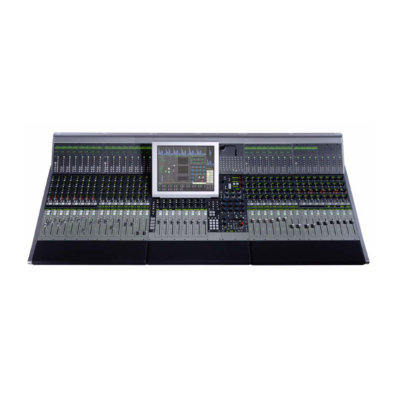
Euphonix Max Air Installation Guide List of Figures Typical Console Layout ......................9 Typical Max Air Room and Equipment Layout ...............20 Max Air Top Dimensions ....................21 Max Air Side Dimensions ....................21 CM416 Bottom Dimensions .....................22 CM404 Bottom Dimensions .....................22 Audio Hookup ........................23 Synchronization Hookup (Word Clock shown, AES/EBU sync may be used) ....24... - Page 6 Euphonix Max Air Installation Guide 3-17 SH612 Studio Hub ......................42 3-18 AM713 Front Panel ......................43 3-19 AM713 Rear Panel ......................44 3-20 MA703 Front Panel ......................46 3-21 MA703 Rear Panel ......................47 3-22 DM714 Front Panel ......................49 3-23 DM714 Rear Panel ......................50 3-24 DM714 Parallel AES/EBU Digital Inputs: Female DB-25 ..........51...
- Page 7 Euphonix Max Air Installation Guide List of Tables Summary of Max Air Components ................15 Max Air Components: Dimensions, Power Consumption, Heat Dissipation ....18 Fuse Ratings for Max Air Components ................. 19 In 1 Elco 38 Pinout ......................35 In 2 Elco 90 Pinout ......................
- Page 8 Euphonix Max Air Installation Guide viii...
-
Page 9: Chapter 1: Max Air Overview
Euphonix Max Air Installation Guide Chapter 1: Max Air Overview This chapter explains the basic elements of any digital audio mixing system and introduces the components of Max Air. It concludes with a section explaining how to estimate your system’s requirements. -
Page 10: Digital Signal Processing
Euphonix Max Air Installation Guide Max Air Overview Channels Max Air has 96 channels. Mono channels may be grouped as stereo or any format up to 7.1, which means that one fader may use one to eight logical channels. Strips Each fully loaded CM416 16-channel Module contains 16 physical faders or strips. -
Page 11: Microphone Inputs
Euphonix has tested several digital sync generators and distribution amplifiers and can supply these devices with the console. Contact a Euphonix sales representative for further information. -
Page 12: System Control Connections
Euphonix Max Air Installation Guide Max Air Overview We recommend following these guidelines: • It is important to minimize the timing differences between signal paths to avoid cumulative timing errors. It is good system engineering practice to send sync signals to all system components from one source. -
Page 13: Estimating System Requirements
Estimating System Requirements This section helps estimate the system requirements for a particular installation. Contact a Euphonix representative for an exact specification. Use the following categories to determine the Max Air components necessary for your studio. Most of the studio details considered here are relevant to any digital mixing system. - Page 14 Euphonix Max Air Installation Guide Max Air Overview Number of DM714 AES/EBU to MADI Converters Each DM714 routes 24 digital inputs (12 AES/EBU pairs) to MADI converters (equipment outputs). Total = (AES/EBU inputs required / 24) Number of MD704 MADI to AES/EBU Converters Each MD704 routes 24 MADI channels to 24 digital outputs (12 AES/EBU pairs) (equip- ment inputs).
-
Page 15: Summary Of Max Air Components
Euphonix Max Air Installation Guide Max Air Overview Table 1-1 Summary of Max Air Components Component Function Number Notes Contains 8 faders for masters, 17-inch Touch- 1 required CM404 Ethernet device screen, and the Superchannel controls. (max) Contains 16 physical faders that control two... - Page 16 Euphonix Max Air Installation Guide Max Air Overview...
-
Page 17: Chapter 2: Interconnecting System Components
Euphonix Max Air Installation Guide Chapter 2: Interconnecting System Components This chapter summarizes technical information for Max Air’s components, including size, weight, power consumption, cooling, and fuse requirements and shows their interconnections. To plan an installation, examine Figure 2-1 to learn about suggested equipment locations. -
Page 18: Component Specifications
Euphonix Max Air Installation Guide Interconnecting System Components Component Specifications Table 2-1 Max Air Components: Dimensions, Power Consumption, Heat Dissipation Typical Power Heat Component Height Width Depth Weight Consumption Dissipation 8.4 in 22.3 in 35.4 in 69 lb PSU 1: 50 W... -
Page 19: Fuse Ratings For Max Air Components
Euphonix Max Air Installation Guide Interconnecting System Components Table 2-2 Fuse Ratings for Max Air Components How to Change Component 100/115/120 VAC 220/230/240 VAC Voltage Setting CM404 T5 A T5 A autoranging CM416 T5 A T5 A autoranging GP132 General Purpose Input/... -
Page 20: Typical Max Air Room And Equipment Layout
Euphonix Max Air Installation Guide Interconnecting System Components Typical Max Air Room and Equipment Layout Studio Optional Machine Room Studio I/O ML 530 Mic-Line IF AM713 A/D Converter Analog IF & Patch IF Control Digital IF & Patch MADI Cue Feeds (from Mon IF) -
Page 21: Console Dimensions
Euphonix Max Air Installation Guide Interconnecting System Components Console Dimensions 29.58 35.43 0.00 5.85 0.00 Figure 2-2 Max Air Top Dimensions 16.25 75.00° Dimensions in inches 16.13 15.625 8.39 6.78 3.06 2.06 1.20 Figure 2-3 Max Air Side Dimensions... -
Page 22: Cm416 Bottom Dimensions
Euphonix Max Air Installation Guide Interconnecting System Components .902 .900 KEEP CLEAR FOR VENTILATION 11.723 12.827 KEEP CLEAR FOR VENTILATION 1/4-20 THREADED INSERT 8 PLACES 23.400 23.648 24.300 24.300 Figure 2-4 CM416 Bottom Dimensions 1.79 KEEP CLEAR FOR PROPER VENTILATION... -
Page 23: Audio Hookup
Euphonix Max Air Installation Guide Interconnecting System Components Audio Hookup Microphone ML530 OUTPUTS INPUTS AM713 1-12 48 Analog 48 Analog 13-24 Studi o Mic Lines ML530 OUTPUTS AM713 INPUTS 48 Analog 1-12 1-48 13-24 Mic Line Interface Analog to MADI... -
Page 24: Synchronization Hookup
Euphonix Max Air Installation Guide Interconnecting System Components Synchronization Hookup OUTPUTS INPUTS AM713 ML530 1-12 W/C In 13-24 Maximum Cable Distances: OUTPUTS INPUTS AM713 Word: 165 ft (50 m) ML530 1-12 W/C In 13-24 Mic Line Interface Analog to MADI... -
Page 25: Madi Hookup
Euphonix Max Air Installation Guide Interconnecting System Components MADI Hookup One DF64 Maximum MADI Cable Distance: 165 ft (50 m) Sources Destinations DF64 MADI Inputs MADI Outputs MA703 MADI to Analog Converter for Mc524 Monitor Interface MM-641 MADI Interface Card... -
Page 26: Control Hookup
Euphonix Max Air Installation Guide Interconnecting System Components Control Hookup Machine Room GP132 Up to six additional Mic/Line MIDI Interfaces Maximum Distances MIDI I/F OUTPUTS INPUTS ML530 1-12 Ethernet: 100 m (330 ft) Fire Wire: 4.5 m (15 ft) Parallel Port... -
Page 27: Chapter 3: Max Air Components
Euphonix Max Air Installation Guide Chapter 3: Max Air Components This chapter discusses the Max Air components and all connectors necessary for operation. Pinouts for user-wired connections are shown for each component, along with the cables and connectors provided by Euphonix. -
Page 28: Fc631, Mm641, And Sp661 Cards
Euphonix Max Air Installation Guide Max Air Components Euphonix Euphonix Euphonix MADI Inputs AES Sync Word Sync MADI Outputs FireWire Chassis ID Sync Source DSP Activity AES Word Int MADI Input OK 44.1 48 Custom Select Locked Active Mute Mute... -
Page 29: Fc631 Frame Controller
Euphonix Max Air Installation Guide Max Air Components FC631 Frame Controller AES Sync In (3-pin Lemo Female): The DF64 Digital Frame clocks to the signal at this port when the sync source is set to AES Sync. Connect this port to a digital sync reference. -
Page 30: Max Air Console
Euphonix Max Air Installation Guide Max Air Components Max Air Console INTERNAL INTERNAL EXTERNAL EXTERNAL TALKBACK MIC TALKBACK MIC TALKBACK MIC TALKBACK MIC SERVICE SERVICE AC IN 1 AC IN 1 AC IN 2 AC IN 2 SERIAL 1 SERIAL 1 T 5.0 AH... -
Page 31: Sc261 System Computer
Euphonix Max Air Installation Guide Max Air Components SC261 System Computer POWERRESET Figure 3-5 SC261 Front and Rear Panels VGA Connector (DB-15): Main video monitor connection. Keyboard (PS2): Main keyboard connection. Mouse (PS2): Main trackball connection. Serial Port 1 (DB-9): Touchscreen control connection. -
Page 32: Pc253D Digital Pilot Computer
Euphonix Max Air Installation Guide Max Air Components PC253d Digital Pilot Computer DIGITAL PILOT COMPUTER 253d PARALLEL PILOT ID 15 16 POWER STATUS MOUSE KEYBOARD PS/2 Figure 3-6 PC253d Front and Rear Panels IEEE 1394 Ports (3 IEEE connectors): Connect any port to IEEE 1394 connector on the FC631 card in the respective DF64 via firewire (provided). -
Page 33: Pc253I Interface Computer
Euphonix Max Air Installation Guide Max Air Components PC253i Interface Computer INTERFACE PILOT COMPUTER 253i PARALLEL PILOT ID 15 16 POWER STATUS MOUSE KEYBOARD PS/2 Figure 3-7 PC253i Front and Rear Panels Parallel Port (DB-25): Connect to MOTU MIDI I/F via DB-25 (provided). -
Page 34: Mc524 Monitor Interface
Listen pre, two Talk Back pre and two Solo channels . Output cable fans out to eight male XLRs. Control (DB15): Input for digital control signal from Digital Pilot (Euphonix TCC bi-di- rectional serial protocol). All patching, switching, and gain controls are communicated via this connection as well as MC524 IP address. -
Page 35: Input/Output Connections
Euphonix Max Air Installation Guide Max Air Components Input/Output Connections Table 3-1 In 1 Elco 38 Pinout Crk # Designator 24 X 32 High Talk 1 Talk 2 Listen 1 Listen 2 Listen 3 Listen 4 Figure 3-9 Elco 38 Connector... -
Page 36: Elco 90 Connector
Euphonix Max Air Installation Guide Max Air Components Table 3-2 In 2 Elco 90 Pinout Crk # Designator 24 X 32 High Cntrl Rm (L) Cntrl Rm (C) Cntrl Rm (R) Cntrl Rm (Sl) Cntrl Rm (Sr) Cntrl Rm (B) -
Page 37: Elco 90 Connector
Euphonix Max Air Installation Guide Max Air Components Table 3-3 Out 1 Elco 90 Pinout Crk # Designator 24 X 32 High BO11 Mon A (L) BO12 Mon A (C) BO17 Mon A (R) BO18 Mon A (Sl) BO19 Mon A (Sr) -
Page 38: Elco 90 Connector
Euphonix Max Air Installation Guide Max Air Components Table 3-4 Out 2 Elco 90 Pinout Crk # Designator 24 X 32 High BO31 Solo L BO32 Solo R Talk 1 Talk 2 Listen 1 Listen 2 Listen 3 Listen 4... -
Page 39: Db-25 Connector
Euphonix Max Air Installation Guide Max Air Components Table 3-5 Out 3 DB-25 Pinout Crk # Designator 24 X 32 High Solo L Solo R 10 9 8 Figure 3-13 DB-25 Connector... -
Page 40: Ml530 Mic/Line Interface
Euphonix Max Air Installation Guide Max Air Components ML530 Mic/Line Interface MIC LINE INTERFACE OUTPUTS INPUTS ML530 1-12 CONTROL 13-24 Figure 3-14 ML530 Front and Rear Panels Inputs (two 38-pin ELCO sockets): A total of 24 microphone inputs are received on two 38-pin ELCO connectors (connectors and pins provided). -
Page 41: Ml530 In 1/In 2 Pinout: Elco 38 Socket
Euphonix Max Air Installation Guide Max Air Components Signal Wiring Instruction & Description Mic In 1 / Mic In 13 From studio Mic 1 / 13 Mic In 2 / Mic In 14 From studio Mic 2 / 14 Mic In 3 / Mic In 15... -
Page 42: Sh612 Studio Hub (Optional)
Euphonix Max Air Installation Guide Max Air Components SH612 Studio Hub (optional) WORD 44.1 INTERNAL Int ->480000 Locked VIDEO SYNC VIDEO Gen ->00:00:00:00 Stop OTHER TC LOCK Info Escape Select VID-SYNC VIDEO VIDEO WORD IEEE1394 Figure 3-17 SH612 Studio Hub Video In (BNC): Connect this to house blackburst or composite sync. -
Page 43: Am713 Analog To Madi Converter
Euphonix Max Air Installation Guide Max Air Components AM713 Analog to MADI Converter Front Panel Figure 3-18 AM713 Front Panel Signal Strength LEDs: Each of the 28 channels has a four-segment LED that represents the following signal levels: -42 dB, -18 dB, -6 dB (green), -0.05 dB (red). -
Page 44: Rear Panel
Euphonix Max Air Installation Guide Max Air Components Rear Panel AM713 DIGITAL ANALOG INPUTS INPUTS MADI Figure 3-19 AM713 Rear Panel Input Voltage Selector: This red switch allows the unit to operate in either 100/110/115 VAC or 220/230/240 VAC environments. A fuse must also be changed for 220/230/240 VAC operation. - Page 45 Euphonix Max Air Installation Guide Max Air Components MADI Out (BNC): Outputs the digital audio signal. • 1–24: Analog inputs • 25–26: Aux analog inputs • 27–28: Aux digital inputs NOTE: 28 channels are always transmitted; dual channels are not used.
-
Page 46: Ma703 Madi To Analog Converter
Euphonix Max Air Installation Guide Max Air Components MA703 MADI to Analog Converter Front Panel Figure 3-20 MA703 Front Panel Signal Strength LEDs: Each of the 28 channels has a four-segment LED that represents the following signal levels: -42 dB, -18 dB, -6 dB (green), -0.05 dB (red). -
Page 47: Rear Panel
Euphonix Max Air Installation Guide Max Air Components Rear Panel MA703 DIGITAL ANALOG OUTPUTS MADI OUTPUTS Figure 3-21 MA703 Rear Panel Input Voltage Selector: This red switch allows the unit to operate in either 100/110/ 115 VAC or 220/230/240 VAC environments. A fuse must also be changed for 220/ 230/240 VAC operation. - Page 48 Euphonix Max Air Installation Guide Max Air Components MADI In (BNC): Digital audio signal input. • 1–24: analog outputs • 25–26: aux analog outputs • 27–28: aux digital outputs.
-
Page 49: Dm714 Aes/Ebu To Madi Converter
Euphonix Max Air Installation Guide Max Air Components DM714 AES/EBU to MADI Converter Front Panel Figure 3-22 DM714 Front Panel Signal Strength LEDs: Each of the 28 channels has a four-segment LED that represents the following signal levels: -42 dB, -18 dB, -6 dB (green), -.05 dB (red). -
Page 50: Rear Panel
Euphonix Max Air Installation Guide Max Air Components Manual Selection Buttons: The button below each Sample Rate LED row manually selects the Sample Rate Source. The DM714 also allows manual selection of the Sample Rate. Power Switch: On/Off switch. Rear Panel... -
Page 51: Dm714 Parallel Aes/Ebu Digital Inputs: Female Db-25
Euphonix Max Air Installation Guide Max Air Components Word Out (BNC): Outputs a Word clock signal synchronized to the Sample Rate Source. In the presence of an external Word clock input, this connector provides a regenerated ver- sion of that input signal. Without an external sample rate source, this connector outputs the internally generated clock signal. -
Page 52: Md704 Madi To Aes/Ebu Converter
Euphonix Max Air Installation Guide Max Air Components MD704 MADI to AES/EBU Converter Front Panel Figure 3-25 MD704 Front Panel Signal Strength LEDs: Each of the 28 channels has a four-segment LED that represents the following signal levels: -42 dB, -18 dB, -6 dB (green), -.05 dB (red). -
Page 53: Rear Panel
Euphonix Max Air Installation Guide Max Air Components Rear Panel BIT-DEPTH REDUCTION MD704 PARALLEL AES/EBU INPUTS 7 / 8 5 / 6 3 / 4 7 / 8 5 / 6 3 / 4 DIGITAL AES/EBU OUTPUTS OUTPUTS MADI D1/D2... -
Page 54: Dm704 Parallel Aes/Ebu Digital Outputs: Female Db-25
Euphonix Max Air Installation Guide Max Air Components MADI In (BNC): Digital audio signal input. • 1–24: main digital outputs • 25–26: aux analog outputs • 27–28: aux digital outputs Bit-Depth Reduction: Sets the resolution to 16, 20, or 24 bits for the main AES/EBU channels. -
Page 55: Fc727/726 Format Converter
MADI A In 1 / MADI A Out 1 (two BNC): The MADI A In/Out Ports interface with non- Euphonix MADI devices. At 48 kHz, MADI A provides 56 channels of 24-bit audio; at 96 kHz, 28 channels of 24-bit audio channels (cable not provided). - Page 56 Euphonix Max Air Installation Guide Max Air Components SDIF-2 or Slave Clock In (BNC): This connector can receive either an SDIF or Slave Clock Sync signal (the FC727 automatically detects the signal type). An SDIF device must send a Word Sync signal to this connector to interface properly. Slave Clock is a sync signal (commonly implemented in Pro Tools systems and referred to as a super-clock) that runs at 256 times the sample rate.
-
Page 57: Aes/Ebu Db-25 Pinout
Euphonix Max Air Installation Guide Max Air Components Table 3-6 AES/EBU DB-25 Pinout Description Pin 1 Pin 2 Channel 1 / 2 In (COLD) Pin 3 Channel 3 / 4 In (GND) Pin 4 Channel 3 / 4 In (HOT) -
Page 58: Common Db-50 Connector Pinout And Usage With Third-Party Devices
Euphonix Max Air Installation Guide Max Air Components Table 3-7 Common DB-50 Connector Pinout and Usage With Third-party Devices Common Connector Pin # (DB50 Female) SDIF usage TDIF usage ProDigi usage ADAT usage ProTools 1 In 1+ In 1+ In 1+... -
Page 59: Fc727 Tdif Cable Wiring Specification
Euphonix Max Air Installation Guide Max Air Components Table 3-8 FC727 TDIF Cable Wiring Specification Connector Pin Connection Description 1 NC 2 J2-1 In 1/2 3 NC 4 J2-2 In 3/4 5 NC 6 J2-3 In 5/6 7 NC 8 J2-4... -
Page 60: Fc727 Pro Tools Cable Wiring Specification
Euphonix Max Air Installation Guide Max Air Components Table 3-9 FC727 Pro Tools Cable Wiring Specification Connector Pin Connection Description In 1/2+ 1 J2-17 In 1/2- 2 J2-42 In 3/4+ 3 J2-16 In 3/4- 4 J2-41 In 5/6+ 5 J2-1... -
Page 61: Fc727 Sdif Cable Wiring Specification
Euphonix Max Air Installation Guide Max Air Components Table 3-10 FC727 SDIF Cable Wiring Specification Connector Pin Connection Description In 1+ 1 J4-2 In 1- 2 J4-1 In 3+ 3 J4-6 In 3- 4 J4-5 In 5+ 5 J4-10 In 5-... -
Page 62: Gp132
Euphonix Max Air Installation Guide Max Air Components GP132 MIDI N.O. C.C. SysX EsBus EAddr Clear All Relays Only Setup GP132 Relays + Tallies NAddr S / R T: pulse T: -ve R: pulse R: NC GP132 AC I MIDI... -
Page 63: Connector Pinouts (Db-25 Rt1-Rt4)
Euphonix Max Air Installation Guide Max Air Components Connector Pinouts (DB-25 RT1–RT4) Table 3-11 GP132 Outputs Common Common Common Common Table 3-12 GP132 Inputs 3,6,9,12,14, Common Common Common Common 17,20,23 WARNING: If power fails on the GP132, none of the relays will function. After restoring...
Need help?
Do you have a question about the Max Air and is the answer not in the manual?
Questions and answers