Sign In
Upload
Manuals
Brands
Digi Manuals
Computer Hardware
NS7520B Series
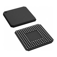
Digi NS7520B Series Microprocessor Manuals
Manuals and User Guides for Digi NS7520B Series Microprocessor. We have
1
Digi NS7520B Series Microprocessor manual available for free PDF download: Hardware Reference Manual
Digi NS7520B Series Hardware Reference Manual (339 pages)
Brand:
Digi
| Category:
Computer Hardware
| Size: 1 MB
Table of Contents
Table of Contents
5
Chapter 1 : a B O U T T H E N S 7 5 2 0
13
NS7520 Features
14
Key Features and Operating Modes of the Major NS7520 Modules
14
NS7520 Module Block Diagram
17
Operating Frequency
18
Chapter 2 : Pinout and Packaging
20
Packaging
20
Pinout Detail Tables and Signal Descriptions
23
System Bus Interface
24
Chip Select Controller
28
Ethernet Interface MAC
30
No Connect" Pins
33
General-Purpose I/O
33
System Clock and Reset
36
System Mode (Test Support)
37
JTAG Test (ARM Debugger)
38
Power Supply
40
Chapter 3 : Working with the CPU
42
ARM Thumb Concept
42
CPU Performance
42
Working with ARM Exceptions
43
Summary of ARM Exceptions
44
Exception Priorities
44
Exception Vector Table
45
Detail of ARM Exceptions
46
Entering and Exiting an Exception (Software Action)
49
Hardware Interrupts
51
FIRQ and IRQ Lines
51
Interrupt Controller
51
Interrupt Sources
52
Chapter 4 : Bbus Module
56
Bbus Masters and Slaves
56
Cycles and Bbus Arbitration
56
Address Decoding
57
Chapter 5 : SYS Module
60
Signal Description
60
JTAG Support
60
ARM Debug
60
System Clock Generation (NS7520 Clock Module)
61
External Oscillator Vs. Internal PLL Circuit
61
NS7520 Clock Module Block Diagram
62
Using the External Oscillator
62
External Oscillator Mode Hardware Configuration
62
Using the PLL Circuit
63
PLL Mode Hardware Configuration
64
Setting the PLL Frequency
66
PLL Settings Register: Setting the PLL Frequency on Bootup
66
Register
69
Reset Circuit Sources
71
NS7520 Bootstrap Initialization
71
Chapter 6 : GEN Module
74
Module Configuration
74
GEN Module Hardware Initialization
74
GEN Module Registers
75
System Control Register
75
System Status Register
80
Software Service Register
81
Timer Control Registers
82
Timer Status Registers
85
PORTA Configuration Register
85
PORTC Configuration Register
89
Interrupts
92
Interrupt Controller Registers
93
Chapter 7 : Memory Controller Module
98
About the MEM Module
98
MEM Module Hardware Initialization
98
Pin Configuration
98
MEM Module Configuration
99
Setting the Chip Select Address Range
100
Memory Module Configuration Register
101
Chip Select Base Address Register
104
Chip Select Option Register a
109
Chip Select Option Register B
113
Static Memory (SRAM) Controller
114
Single Cycle Read/Write
114
Burst Cycles
116
NS7520 DRAM Address Multiplexing
117
Using the Internal Multiplexer
117
Using the External Multiplexer
120
DRAM Refresh
121
FP/EDO DRAM Controller
121
Single Cycle Read/Write
122
FP/EDO DRAM Burst Cycles
123
Sdram
123
NS7520 SDRAM Interconnect
124
SDRAM A10/AP Support
128
Command Definitions
129
Memory Timing Fields - SDRAM
130
BSIZE Configuration
130
SDRAM Mode Register
131
SDRAM Read Cycles
132
SDRAM Write Cycles
134
Peripheral Page Burst Size
136
Chapter 8 : DMA Module
140
DMA Module
140
Fly-By Operation Transfers
140
Memory-To-Memory Operation
141
DMA Buffer Descriptor
142
DMA Channel Assignments
144
DMA Channel Registers
145
Address Map
145
Buffer Descriptor Pointer Register
148
DMA Control Register
148
DMA Status/Interrupt Enable Register
154
Ethernet Transfer Considerations
156
Ethernet Transmitter Considerations
157
Ethernet Receiver Considerations
157
External Peripheral DMA Support
158
Signal Description
159
External DMA Configuration
159
Memory-To-Memory Mode
159
DMA Controller Reset
160
Chapter 9 : Ethernet Module
162
Ethernet Front-End (EFE)
162
Transmit and Receive Fifos
163
EFE Transmit Processing
163
EFE Receive Processing
163
Receive Buffer Descriptor Selection
164
External CAM Filtering
165
MAC Module
166
MAC Module Block Diagram
166
DMA Channel Assignments
168
EFE Configuration
168
Ethernet General Control Register (EGCR) Bit Definitions
170
Ethernet General Status Register (EGSR) Bit Definitions
176
Ethernet FIFO Data Register
179
Ethernet Transmit Status Register
180
Ethernet Receive Status Register
185
MAC Configuration Register 1
188
MAC Configuration Register 2
190
Back-To-Back Inter-Packet-Gap Register
194
Non-Back-To-Back Inter-Packet-Gap Register
195
Collision Window/Collision Retry Register
196
Maximum Frame Register
197
PHY Support Register
198
Test Register
199
MII Management Configuration Register
201
MII Management Command Register
203
MII Management Address Register
204
MII Management Write Data Register
205
MII Management Read Data Register
206
MII Management Indicators Register
207
SMII Status Register
208
Station Address Registers
208
Station Address Filter Register
211
Register Hash Table
212
Chapter 10 : Serial Controller Module
220
Supported Features
220
Bit-Rate Generator
221
Serial Protocols
222
UART Mode
222
SPI Mode
223
FIFO Management
224
General-Purpose I/O Configurations
232
Serial Port Performance
233
Configuration
233
Serial Channel Registers
235
Serial Channel 1, 2 Control Register a
235
Serial Channel 1, 2 Control Register B
241
Serial Channel 1, 2 Status Register a
245
Serial Channel 1, 2 Bit-Rate Registers
253
Serial Channel 1, 2 FIFO Registers
262
Serial Channel 1, 2 Receive Buffer Gap Timer
262
Serial Channel 1, 2 Receive Character Gap Timer
264
Serial Channel 1,2 Receive Match Register
266
Serial Channel 1, 2 Receive Match MASK Register
266
Chapter 11 : Electrical Characteristics
270
DC Characteristics
270
Recommended Operating Conditions
270
Input/Output Characteristics
271
Pad Pullup and Pulldown Characteristics
271
Absolute Maximum Ratings
273
AC Characteristics
273
AC Electrical Specifications
273
Oscillator Characteristics
275
Timing Diagrams
277
Timing_Specifications
277
Reset_Timing
278
SRAM Timing
279
SDRAM Timing
289
FP DRAM Timing
295
Ethernet Timing
302
JTAG Timing
304
External DMA Timing
306
Serial Internal/External Timing
309
GPIO Timing
311
Chapter 1 2 : N S 7 5 2 0 E R R a T a
313
How to Identify the NS7520
314
NS7520 Errata
315
Clock Speed Errata Using PLL in Boundary Scan Mode
315
UART CTS-Related Transmit Data Errors
315
EDO Burst Errata
316
NS7520 Clock Speed Erratum
318
SPI Slave Mode Errata
320
Error in "No Connect" Pin Terminations
320
Serial Port Error in 7-Bit Mode
321
SDRAM 256 MB Mask Failure
321
Erroneous Timeouts When Loading Timer
321
Station Address Logic: Multicast and Broadcast Packet Filtering
322
Station Address Logic: Unicast Packets
322
Corrupt Ethernet Receive Packets
323
Transmit Buffer Closed Bit Is Not Functional
324
Transmit FIFO Timing Issue
324
External Use of TA_ and TEA
325
Advertisement
Advertisement
Related Products
Digi NS7520B-1-C36
Digi NS7520B-1-I46
Digi NS7520B-1-C55
Digi NS9215
Digi NS9210
Digi NS7520
Digi NS9750
Digi NET+50
Digi NET+20M
Digi NetSilicon Connectware Connect Series
Digi Categories
Network Router
Control Unit
Modem
Gateway
Server
More Digi Manuals
Login
Sign In
OR
Sign in with Facebook
Sign in with Google
Upload manual
Upload from disk
Upload from URL