Sign In
Upload
Manuals
Brands
Danfoss Manuals
Water Pump
H1 Series
Danfoss H1 Series Manuals
Manuals and User Guides for Danfoss H1 Series. We have
8
Danfoss H1 Series manuals available for free PDF download: Technical Information, Service Manual, Basic Information
Danfoss H1 Series Technical Information (144 pages)
Bent Axis Motors
Brand:
Danfoss
| Category:
Engine
| Size: 10 MB
Table of Contents
Table of Contents
3
Contents
6
H1 General Information
6
Design of H1 Bent Axis Motor
6
General Description
8
The H1 Range of Products
8
H1 Pictorial Diagram
9
H1 System Schematic
10
Technical Specifications
11
General Specifications
11
Physical Properties
11
Operating Parameters
12
H1B Speed Range Diagrams for Open and Closed Circuit
13
Required Inlet Pressure Diagrams (for Cylinder Block Filling)
14
Required Outlet Pressure Diagrams (Minimum for Short Time Usage)
15
Required Low Pressure Diagrams (Minimum for Extended Usage)
16
Open Circuit Requirements
17
Fluid Specifications
17
Determination of Nominal Motor Size
18
Operation
19
Shaft Rotation Direction
19
Loop Flushing Shuttle Spool
20
Loop Flushing Relief Valve
21
Displacement Limiter
21
Speed Sensor
22
Sensor Position
24
Target Ring
24
Operating Parameters
25
Output Speed
25
System Pressure
26
Case Pressure
26
External Shaft Seal Pressure
26
Temperature
27
Viscosity
27
System Design Parameters
28
Filtration System
28
Reservoir
28
Fluid Selection
29
Case Drain
29
Independent Braking System
29
Bearing Loads and Life
29
Shaft Torque
29
Master Model Code
30
Control Operation and Description
36
Electric Controls
36
Electric Proportional Controls
36
Electric Two-Position Controls
36
Servo Supply
36
Control Options
37
Pcor
37
Electric Proportional with PCOR
37
Electric Two-Position with PCOR
37
Electric Two-Position with Proportional PCOR
37
Hydraulic Controls
38
Hydraulic Proportional Control
38
Hydraulic Two-Position Control
38
Hydraulic Proportional with PCOR
39
Hydraulic Two-Position with PCOR
39
Brake Pressure Defeat (BPD)
40
Electric BPD
40
Electric Solenoid Connector
40
Hydraulic BPD
40
Applications Related to Controls
41
Controls - Nomenclature, Description
42
Options L1BA, L2BA - Electric Proportional Control
42
Options D1MA, D2MA - Electric Proportional Control with PCOR
44
Options D1M1, D2M2 - Electric Proportional Control with PCOR and Electric BPD
46
Options M1CA, M2CA - Electric Proportional Control
48
Options K1KA, K2KA - Electric Proportional Control with PCOR
50
Options K1K1, K2K2 - Electric Proportional Control with PCOR and Electric BPD
52
Options E1AA, E2AA - Electric Two-Position Control
54
Options F1EA, F2EA - Electric Two-Position Control
55
Options T1DA, T2DA - Electric Two-Position Control with PCOR
56
Options T1D1, T2D2 - Electric Two-Position Control with PCOR and Electric BPD
58
Options T1G1, T2G2 - Electric Two-Position Control with PCOR and Electric BPD
60
Options P1DA, P2DA - Electric Two-Position Control with PCOR
62
Options P1D1, P2D2 - Electric Two-Position Control with PCOR and Electric BPD
64
Options P1G1, P2G2 - Electric Two-Position Control with PCOR and Electric BPD
66
Option LHBA - Hydraulic Proportional Control
68
Option MHCA - Hydraulic Proportional Control
70
Option DHMA - Hydraulic Proportional Control with PCOR
72
Option DHMH - Hydraulic Proportional Control with PCOR and BPD
74
Option KHKA - Hydraulic Proportional Control with PCOR
76
Option KHKH - Hydraulic Proportional Control with PCOR and BPD
78
Option HEHE - Hydraulic Two-Position Control
80
Option HFHF - Hydraulic Two-Position Control
81
Option THHA - Hydraulic Two-Position Control with PCOR
82
Option THHB - Hydraulic Two-Position Control with PCOR and Hydraulic BPD
83
Pressure Compensator Override with Brake Pressure Defeat Configuration
84
Option TADA - Pressure Compensator over Ride
85
Options TAD1, TAD2 - Pressure Compensator over Ride and Electric BPD
86
Options TAG1, TAG2 - Pressure Compensator over Ride and Electric BPD
88
H1B Control Response
89
SAE Flange Design - Option L* (Proportional Control)
90
SAE Flange Design - Option M* (Proportional Control)
92
SAE Flange Design - Options T* D* and P* D* (Two-Position Control, PCOR, Electric BPD)
94
SAE Flange Design Ports Per ISO 11 926-1
96
SAE Mounting Flange Design Per ISO 3019/1
97
O-Ring Groove Dimensions
99
DIN Flange Design - Option L* (Proportional Control)
100
DIN Flange Design - Option M* (Proportional Control)
102
DIN Flange Design - Options T* D* and P* D* (Two-Position Control, PCOR, Electric BPD)
104
DIN Flange Design Ports Per ISO 11 926-1
106
DIN Mounting Flange Design Per ISO 3019/2
107
Notes
109
Cartridge Flange Design - Option L* (Proportional Control)
110
Cartridge Flange Design - Option M* (Proportional Control)
112
Cartridge Flange Design - Options T* D* and P* D* (Two-Position Control, PCOR, Electric BPD)
114
Cartridge Flange Design Ports Per ISO 11 926-1
116
Cartridge Mounting Flange Design
117
H1B Cartridge Motors with Speed Sensor
120
Dimensions - Controls on H1B Motors
121
Options L1BA and L2BA (Electric Proportional Control)
121
Option D*MA (Electric Proportional Control)
122
Option D*M* (Electric Proportional Control)
123
Options M1CA and M2CA (Electric Proportional Control)
124
Option K*KA (Electric Proportional Control)
125
Options K1K1 and K2K2 (Electric Proportional Control with PCOR and BPD)
126
Options E1AA and E2AA (Electric Two-Position Control)
127
Options F1EA and F2EA (Electric Two-Position Control)
128
Options T1DA, T2DA and P1DA, P2DA (Electric Two-Position Controls with PCOR and Electric Proportional PPCOR)
129
Options T1D1, T2D2 and P1D1, P2D2 (Electric Two-Position Controls with PCOR, BPD and Electric Proportional PPCOR, BPD)
130
Option LHBA (Hydraulic Proportional Control)
132
Option MHCA (Hydraulic Proportional Control)
133
Option DHMA (Hydraulic Proportional Control)
134
Option DHMH (Hydraulic Proportional Control)
135
Option HEHE (Hydraulic Two-Position Control)
137
Option HFHF (Hydraulic Two-Position Control)
138
Option THHA (Hydraulic Two-Position Control)
139
Option THHB (Hydraulic Two-Position Control)
140
Option TADA (Hydraulic Two-Position Control)
142
Option TAD1 and TAD2 (Hydraulic Two-Position Control)
143
Advertisement
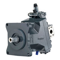
Danfoss H1 Series Service Manual (72 pages)
Closed Circuit Axial Piston Pumps 45/53/60/68 Tandem
Brand:
Danfoss
| Category:
Water Pump
| Size: 8 MB
Table of Contents
Table of Contents
3
Overview
5
Warranty
5
General Instructions
5
Remove the Unit
5
Replace All O-Rings and Gaskets
5
Safety Precautions
6
Unintended Machine Movement
6
Flammable Cleaning Solvents
6
Fluid under Pressure
6
Personal Safety
6
Symbols Used in Danfoss Literature
6
Design
7
Pump Schematic
8
The System Circuit
9
Operation
11
Pressure Limiter Valves (060/068 Only)
11
High Pressure Relief Valve (HPRV) and Charge Check
11
Charge Pressure Relief Valve
12
Electrical Displacement Control (EDC)
13
Manual Override (MOR)
14
Manual Displacement Control (MDC)
15
Control-Cut-Off (CCO) Valve and Brake Valve
17
Operating Parameters
20
Overview
20
Input Speed
20
System Pressure
20
Charge Pressure
20
Charge Inlet Pressure
21
Case Pressure
21
Temperature and Viscosity
21
Temperature
21
Viscosity
21
Technical Specifications
22
H1T General Specifications
22
Technical Data H1 Tandem
22
Operating Parameters H1 Tandem
23
Fluid Specifications
23
Fluid and Filter Maintenance
25
Fluid and Filter Recommendations
25
Hazardous Material
25
Pressure Measurements
26
Port Locations and Gauge Installation - 045/053
26
Port Locations and Gauge Installation - 060/068
27
Initial Startup Procedures
28
General
28
Start-Up Procedure
28
Troubleshooting
29
Overview
29
Safety Precautions
29
Electrical Troubleshooting
29
Neutral Difficult or Impossible to Find
30
System Operating Hot
30
Transmission Operates Normally in One Direction Only
30
System will Not Operate in Either Direction
30
System Noise or Vibration
31
Sluggish System Response
31
Adjustments
32
Pump Adjustment
32
Standard Procedures
32
Charge Pressure Relief Valve Adjustment
32
Charge Check / HPRV Adjustment
34
Pressure Limiter Adjustment (060/068 Only)
34
Engaging the Bypass Function (060/068 Only)
38
Displacement Limiter Adjustment
39
Control Neutral Adjustment
40
Mechanical Neutral Adjustment
42
Pump Setup
43
Servo Adjustment
44
Minor Repair
47
Standard Procedures, Removing the Pump
47
Electric Control Module
47
Control Solenoids
49
MDC Control
49
MDC Illustration - Tandems
50
MDC Legend - Tandems
50
Angle Sensor on EDC
52
Removal
52
Installation
52
EDC with Angle Sensor
53
Removal
53
Installation
53
Front Shaft, Seal, and Bearing
54
Charge Pump (045/053 Only)
56
Assembly
58
Charge Check / HPRV (45/53)
58
Hprv (60/68)
60
Removal
60
Inspection
60
Reassembly
60
Charge Pressure Relief Valve
61
Control Cutoff Valve and Brake Valve
63
Torque Chart
66
Fastener Size and Torque Chart
66
Plug Size and Torque Chart
66
Fasteners and Plugs
67
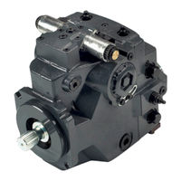
Danfoss H1 Series Technical Information (72 pages)
Axial Piston Single Pumps
Brand:
Danfoss
| Category:
Water Pump
| Size: 11 MB
Table of Contents
Table of Contents
3
Contents
5
Technical Specifications
5
H1 Pumps General Specification
5
H1P 115/130 Technical Data
5
H1P 115/130 Operating Parameters
6
Fluid Specifications
7
Bearing Life and External Radial Shaft Loads
7
H1P 115/130 Mounting Flange Loads
8
Charge Pump
9
Charge Pump Selection
9
26/34 CM³ Charge Pump - Flow and Power Curves
9
Master Model Code
10
Control Options
17
Electrical Displacement Control (EDC)
17
EDC Control Signal Requirements
17
EDC Solenoid Data
18
Control Response
18
Response Time, EDC 115/130
19
Manual Displacement Control (MDC)
20
MDC Torque
20
MDC General Information
21
MDC Shaft Rotation
21
Control Response
22
MDC Response Time
22
Neutral Start Switch (NSS)
22
Connector
23
Case Gauge Port M14
23
Lever
23
Forward-Neutral-Reverse Electric Control (FNR)
24
Control Response
26
Response Time, FNR 115/130
26
Non Feedback Proportional Electric Control (NFPE)
27
Control Signal Requirements, NFPE 115/130
27
Control Response
29
NFPE Response Time
29
Automotive Control (AC)
30
Mode Types
30
Basic Functions
30
Performance Functions
31
Protection and Safety Functions
31
Engine Control and Protection
31
Installation Features
31
Fan Drive Control (FDC)
32
Control Signal Requirements, FDC 115/130
32
Control Response
34
Response Time, FDC 115/130
34
Manual Override (MOR)
35
Swash Plate Angle Sensor for EDC Controls
36
Swash Plate Angle Sensor Parameters (EDC)
36
Swash Plate Angle Sensor Connector
37
Interface with ECU
37
Swash Plate Angle Sensor for NFPE and AC2 Controls
38
Swash Plate Angle Sensor Parameters (NFPE/AC)
38
Swash Plate Angle Sensor Connector
39
Interface with ECU
39
Control-Cut-Off Valve (CCO Valve)
40
CCO Solenoid Data
41
Brake Gauge Port with MDC
41
Displacement Limiter
41
H1P 115/130 Displacement Change (Approximately)
41
Contents
42
Dimensions
42
H1P Input Shaft - Option G3 (SAE D, 13 Teeth)
42
H1P Input Shaft - Option G2 (SAE D, 27 Teeth)
43
H1P Input Shaft - Option F3, Code 44-3
44
Tapered Shaft Customer Acknowledgement
45
H1P 115/130 Auxiliary Mounting - Option H1 (SAE A, 11 Teeth)
46
H1P 115/130 Auxiliary Mounting - Option H2 (SAE A, 9 Teeth)
47
H1P 115/130 Auxiliary Mounting - Option H3 (SAE B, 13 Teeth)
48
H1P 115/130 Auxiliary Mounting - Option H4 (SAE D, 13 Teeth)
49
H1P 115/130 Auxiliary Mounting - Option H5 (SAE B-B, 15 Teeth)
50
H1P 115/130 Auxiliary Mounting - Option H6 (SAE C, 14 Teeth)
51
H1P 115/130 Auxiliary Mounting - Option S1 (SAE B-B, 14 Teeth)
52
H1P 115/130 Displacement Limiter, Option B and D
53
Installation Drawings
54
Port Description H1P115/130
54
Dimensions H1P 115/130
56
Controls
59
Electric Displacement Control (EDC), Option A2 (12 V) / A3 (24 V)
59
Electric Displacement Control (EDC) with MOR, Options A4 (12 V) / A5 (24 V)
59
H1P 115/130 Manual Displacement Control (MDC), Option M1
60
H1P 115/130 Manual Displacement Control (MDC) with NSS, Option M2
61
H1P 115/130 Manual Displacement Control (MDC) with CCO, Option M3, M4
62
H1P 115/130 Manual Displacement Control (MDC) with NSS and CCO, Option M5, M6
63
Non Feedback Proportional Electric Control (NFPE), with Manual Override, Option A8 (12 V) / B8 (24 V)
64
Automotive Control (AC) Dimensions
65
Forward-Neutral-Reverse (FNR) with Manual Override, Options A9 (12 V) / B1 (24 V)
66
Filtration
67
H1P 115/130 Suction Filtration, Option L
67
H1P 115/130 Filtration, Option M
68
Advertisement
Danfoss H1 Series Technical Information (68 pages)
Axial Piston Single Pumps; Size 069/078
Brand:
Danfoss
| Category:
Water Pump
| Size: 8 MB
Table of Contents
Table of Contents
3
H1P General Specifications
5
Technical Data H1P 069/078
5
Operating Parameters H1P 069/078
6
Fluid Specifications H1P
6
External Radial Shaft Loads
7
Bearing Life H1P 069/078
7
Mounting Flange Loads H1P 069/078
7
Charge Pump
9
Charge Pump Sizing/Selection
9
Charge Pump Flow and Power Curves, 14/17 CM³
9
Master Model Code H1P 069/078
12
Control Options
16
Electrical Displacement Control (EDC), Options: A2 (12 V) / A3 (24 V)
16
EDC Control Signal Requirements
16
EDC Solenoid Data
17
Control Response
17
Response Time EDC 069/078
18
Manual Displacement Control (MDC)
19
MDC Principle
19
MDC General Information
20
Shaft Rotation MDC
20
Control Response
20
Response Time, MDC 069/078
21
Neutral Start Switch (NSS)
21
Case Gauge Port M14
22
Lever
22
Forward-Neutral-Reverse Electric Control (FNR), Options: A9 (12 V) and B1 (24 V)
23
Control Response
24
Response Time, FNR
24
Non Feedback Proportional Electric Control (NFPE), Options: A8 (12 V) / B8 (24 V)
25
Control Signal Requirements, NFPE 069/078
25
Control Response
26
Response Time, NFPE 069/078
27
Automotive Control (AC)
28
Mode Types
28
Basic Functions
28
Performance Functions
29
Protection and Safety Functions
29
Engine Control and Protection
29
Installation Features
29
Fan Drive Control (FDC), Options: F1 (12V) / F2 (24V)
30
Control Response
32
Response Time, FDC 069/078
32
Manual Override (MOR)
33
Swash Plate Angle Sensor for AC2 Controls
34
Swash Plate Angle Sensor Parameters
34
Swash Angle Sensor Connector
34
Swashplate Angle Vs Output Voltage Graph with Calculation Formula
35
Interface with ECU
35
Control-Cut-Off Valve (CCO Valve)
36
CCO Solenoid Data
36
Brake Gauge Port with MDC
37
Displacement Limiter
38
Displacement Change (Approximately) H1P 069/078
38
Dimensions
39
H1P Input Shaft - Option G1 (SAE C, 14 Teeth)
39
H1P Input Shaft - Option G9 (SAE C-C, 23 Teeth)
40
H1P Input Shaft - Option F1 (SAE C, 21 Teeth)
41
H1P Input Shaft, Option F4, Code 38-3
42
Tapered Shaft Customer Acknowledgement
42
H1P Auxiliary Mounting, Option H2 (SAE A, 9 Teeth)
43
H1P Auxiliary Mounting, Option H1 (SAE A, 11 Teeth)
44
H1P Auxiliary Mounting, Option H3 (SAE B, 13 Teeth)
45
H1P Auxiliary Mounting, Option H5 (SAE B-B, 15 Teeth)
46
H1P Auxiliary Mounting, Option H6 (SAE C, 14 Teeth)
47
H1P 069/078 Displacement Limiter, Option B
48
Installation Drawings
49
Ports Description H1P 069/078
49
Dimensions H1P 069/078
51
Controls
54
Electric Displacement Control (EDC), Option A2 (12 V)/A3 (24 V)
54
Electric Displacement Control (EDC), with MOR, Option A4 (12 V)/A5 (24 V)
54
H1P 069/078 Manual Displacement Control (MDC), Option M1
55
H1P 069/078 Manual Displacement Control (MDC) with CCO, Option M3, M4
56
H1P 069/078 Manual Displacement Control (MDC) with NSS, Option M2
57
H1P 069/078 Manual Displacement Control (MDC) with NSS and CCO, Option M5, M6
58
Forward-Neutral-Reverse (FNR) with Manual Override, Option A9 (12 V)/B1 (24 V)
59
Non Feedback Proportional Electric Control (NFPE), with MOR, Option A8 (12 V)/B8 (24 V)
60
Non Feedback Proportional Electric Control (NFPE) with Angle Sensor
61
Automotive Controls with MOR: AC I - Options A7 (12V) / C2 (24V) and AC II - Options B7 (12V) / C3 (24V)
62
Fan Drive Control (FDC), Option F1 (12V) / F2 (24V)
63
Filtration
64
H1P 069/078, Suction Filtration, Option L
64
Remote Full Charge Pressure Filtration, Option P for End Cap Option F5 (SAE-C PTO)
64
Integral Full Flow Charge Pressure Filtration with Filter Bypass Sensor, Option M
65
External Full Flow Charge Pressure Filtration, Option S for End Cap Options D8 or F5
66
Danfoss H1 Series Technical Information (68 pages)
Axial Piston Single Pumps Size 060/068
Brand:
Danfoss
| Category:
Water Pump
| Size: 10 MB
Table of Contents
Table of Contents
3
H1 Pump General Specification
5
Technical Data H1P 060/068
5
Operating Parameters H1P 060/068
6
Fluid Specifications
6
External Radial Shaft Loads
7
Bearing Life H1P 060/068
7
Mounting Flange Loads H1P 060/068
8
Charge Pump
9
Charge Pump Selection
9
Charge Pump Flow and Power Curves, 14/17 Cm3
9
Master Model Code
10
Control Options
17
Electrical Displacement Control (EDC)
17
EDC Control Signal Requirements
17
EDC Solenoid Data
18
Control Response
18
Response Time, EDC 060/068
19
Manual Displacement Control (MDC)
20
MDC Torque
20
MDC General Information
21
MDC Shaft Rotation
21
Control Response
21
Response Time, MDC 060/068
22
Neutral Start Switch (NSS)
22
Case Gauge Port M14
23
Lever
23
Forward-Neutral-Reverse Electric Control (FNR), Options: A9 (12 V) and B1 (24 V)
24
Control Response
25
FNR Response Time 060/068
25
Non Feedback Proportional Electric Control (NFPE)
26
Control Signal Requirements, NFPE 060/068
27
Control Response
28
Response Time, NFPE 060/068
28
Automotive Control (AC)
29
Mode Types
29
Basic Functions
29
Performance Functions
30
Protection and Safety Functions
30
Engine Control and Protection
30
Installation Features
30
Fan Drive Control (FDC)
31
Control Response
32
Response Time, FDC
32
Manual over Ride (MOR)
33
Swash Plate Angle Sensor for NFPE and AC2 Controls
34
Swash Plate Angle Sensor Parameters
34
Swash Plate Angle Sensor Connector
35
Interface with ECU
35
Control-Cut-Off Valve (CCO Valve)
36
CCO Solenoid Data
36
Brake Gauge Port with MDC
37
Displacement Limiter
38
Displacement Change (Approximately) H1P 060/068
38
Dimensions
39
Input Shaft, Option G1 (SAE C, 14 Teeth)
39
Input Shaft, Option F1 (SAE C, 21 Teeth) 045/053
40
H1P Auxiliary Mounting, Option H2 (SAE A, 9 Teeth)
41
11071685 | Bc00000074En-US0701
42
H1P Auxiliary Mounting, Option H1 (SAE A, 11 Teeth)
42
H1P Auxiliary Mounting, Option H3 (SAE B, 13 Teeth)
43
H1P Auxiliary Mounting, Option H5 (SAE B-B, 15 Teeth)
44
H1P Auxiliary Mounting, Option H6 (SAE C, 14 Teeth)
45
H1P 060/068 Displacement Limiter, Option B
45
Installation Drawings
46
Port Description H1P 060/068
46
Dimensions H1P 060/068
48
Controls
51
Electric Displacement Control (EDC), Options: A2 (12 V) / A3 (24 V)
51
Electric Displacement Control (EDC) with MOR, Options: A4 (12 V) / A5 (24 V)
51
H1P 060/068 Manual Displacement Control (MDC), Option M1
52
H1P 060/068 Manual Displacement Control (MDC) with NSS, Option M2
53
H1P 060/068 Manual Displacement Control (MDC) with CCO, Option M3, M4
54
H1P 060/068 Manual Displacement Control (MDC) with NSS and CCO, Option M5, M6
55
Forward-Neutral-Reverse (FNR) with MOR, Options: A9 (12 V) / B1 (24 V)
56
Non Feedback Proportional Electric Control (NFPE), with MOR, Option A8 (12 V)/B8 (24 V)
57
Automotive Control (AC) Dimensions
58
Fan Drive Control (FDC), Option F1 (12V) / F2 (24V)
59
Filtration
60
H1P 060/068, Suction Filtration, Option L
60
Remote Full Charge Pressure Filtration, Option P for End Cap Option F (SAE-C PTO)
61
Integral Full Flow Charge Pressure Filtration with Filter Bypass Sensor, Options M / D3, F4
62
External Full Flow Charge Pressure Filtration, Option E / D8, F5
64
Danfoss H1 Series Technical Information (64 pages)
Axial Piston Single Pumps Size 147/165
Brand:
Danfoss
| Category:
Water Pump
| Size: 9 MB
Table of Contents
Table of Contents
3
Technical Specifications
5
H1 Pump General Specification
5
H1P 147/165 Technical Data
5
H1P 147/165 Operating Parameters
6
Fluid Specifications
6
External Radial Shaft Loads
7
H1P 147/165 Bearing Life
7
H1P 147/165 Mounting Flange Loads
8
Charge Pump Selection
8
Charge Pump Curves, Size 26/34 CM³
8
Master Model Code
10
Control Options
17
Electrical Displacement Control (EDC)
17
EDC Control Signal Requirements
17
EDC Solenoid Data
18
Control Response
18
EDC Response Time
19
Manual Displacement Control (MDC)
20
MDC Torque
20
MDC General Information
21
MDC Shaft Rotation
21
Control Response
21
MDC Response Time
22
Neutral Start Switch (NSS)
22
Case Gauge Port M14
23
Lever
23
Forward-Neutral-Reverse Electric Control (FNR), Options: A9 (12 V) and B1 (24 V)
24
Control Response
25
FNR Response Time - H1P 147/165
25
Non Feedback Proportional Electric Control (NFPE)
26
NFPE Control Signal Requirements
28
Control Response
29
NFPE Response Time - H1P 147/165
29
Automotive Control (AC)
30
Mode Types
30
Basic Functions
30
Performance Functions
31
Protection and Safety Functions
31
Engine Control and Protection
31
Installation Features
31
Fan Drive Control (FDC)
32
Control Response
33
FDC Response Time
33
Manual Override (MOR)
34
Swash Plate Angle Sensor for NFPE and AC2 Controls
35
Swash Plate Angle Sensor Parameters
35
Swash Plate Angle Sensor Connector
36
Interface with ECU
36
Control-Cut-Off Valve (CCO Valve)
37
CCO Solenoid Data
38
Brake Gauge Port with MDC
38
Displacement Limiter
39
Displacement Change (Approximately) H1P 147/165
39
Dimensions
40
H1P Input Shaft - Option G2 (SAE D, 27 Teeth)
40
H1P Input Shaft - Option G3 (SAE D, 13 Teeth)
41
H1P Input Shaft - Option F3, Code 44-3
42
Tapered Shaft Customer Acknowledgement
42
H1P 147/165 Auxiliary Mounting, Option H2 (SAE A, 9 Teeth)
43
H1P 147/165 Auxiliary Mounting, Option H1 (SAE A, 11 Teeth)
44
H1P 147/165 Auxiliary Mounting, Option H3 (SAE B, 13 Teeth)
45
H1P 147/165 Auxiliary Mounting, Option H5 (SAE B-B, 15 Teeth)
46
H1P 147/165 Auxiliary Mounting, Option H6 (SAE C, 14 Teeth)
47
H1P 147/165 Auxiliary Mounting, Option H4 (SAE D, 13 Teeth)
48
H1P 147/165 Displacement Limiter, Option B
49
Installation Drawings
50
Port Description H1P 147/165
50
Dimensions H1P 147/165
52
Controls
55
Electric Displacement Control (EDC), Option A2 (12 V) / A3 (24 V)
55
Electric Displacement Control (EDC) with MOR, Option A4 (12 V) / A5 (24 V)
55
H1P 147/165 Manual Displacement Control (MDC), Option M1
56
H1P 147/165 Manual Displacement Control (MDC) with NSS, Option M2
57
H1P 147/165 Manual Displacement Control (MDC) with CCO, Option M3, M4
58
H1P 147/165 Manual Displacement Control (MDC) with NSS and CCO, Option M5, M6
59
Automotive Control (AC) Dimensions
60
Forward-Neutral-Reverse (FNR) with Manual Override, Options A9 (12 V) / B1 (24 V)
61
Filtration
62
Suction Filtration, Option L, H1P 147/165
62
Integral Full Flow Charge Pressure Filtration with Filter Bypass Sensor, Option M, H1P 147/165
63
Danfoss H1 Series Technical Information (52 pages)
Axial Piston Pump, Size 045/053, Single
Brand:
Danfoss
| Category:
Water Pump
| Size: 5 MB
Table of Contents
Table of Contents
3
Contents
5
Technical Specifications
5
H1P General Specifications
5
Technical Data H1P 045/053
5
Operating Parameters H1P 045/053
5
H1P Fluid Specifications
6
General Technical Specifications
7
Shaft Loads H1P 045/053 Single
7
External Radial Shaft Loads
7
Bearing Life H1P 045/053
7
Mounting Flange Loads H1P 045/053
8
H1 Single Pump Front Flange Load
8
Model Code
9
Model Code H1P 045/053
9
Control Options
13
Electrical Displacement Control (EDC) Options A2 (12 V)/A3 (24 V)
13
EDC Principle
13
Control Signal Requirements
14
Connector
14
Control Response
15
Response Time, EDC 045/053 S
15
Forward-Neutral-Reverse (FNR) Electric Control Options A9 (12 V)/B1 (24 V)
15
Solenoid Connector
16
Control Response
17
Response Time, FNR 045/053
18
Non Feedback Proportional Electric Control (NFPE) Options A8 (12 V)/B8 (24 V)
18
Control Signal Requirements
19
Connector
19
Control Response
20
Respose Time, NFPE 045/053
20
Automotive Control (AC)
20
Mode Types
21
Basic Functions
21
Performance Functions
22
Protection and Safety Functions
22
Engine Control and Protection
22
Installation Features
22
Fan Drive Control (FDC) Option F1 (12V)/F2 (24V)
22
Control Signal Requirements
23
Connector
24
Control Response
25
Response Time, FDC 045/053
25
Manual over Ride (MOR)
25
Displacement Limiter
26
Displacement Change (Approximately) H1P 045/053 S
27
Dimensions
28
Input Shafts
28
H1P Input Shaft - Option G4 (SAE B, 13 Teeth)
28
H1P Input Shaft - Option G5 (SAE B-B, 15 Teeth)
28
H1P Input Shaft - Option G1 (SAE B, 14 Teeth)
29
H1P Input Shaft - Option F2, Code 25-3
30
Tapered Shaft Customer Acknowledgement
30
Auxiliary Mounting Pads
31
H1P Auxiliary Mounting - Option H2 (SAE A, 9 Teeth)
31
H1P Auxiliary Mounting - Option H1 (SAE A, 11 Teeth)
32
H1P Auxiliary Mounting - Option H3 (SAE B, 13 Teeth)
32
H1P Auxiliary Mounting - Option H5 (SAE B-B, 15 Teeth)
33
Charge Pump
34
Charge Pump Sizing/Selection
34
Charge Pump Flow and Power Curves 12 CM³
34
Installation Drawings
35
Port Description H1P 045/053 Single
35
Dimensions H1P 045/053 Single
37
Controls
40
Electric Displacement Control (EDC), Option A2 (12V) / A3 (24V)
40
Electric Displacement Control (EDC) with Manual Override, Option A4 (12 V) / A5 (24 V)
41
Forward-Neutral-Reverse (FNR) with Manual Override, Option A9 (12 V) B1 (24 V)
42
Non Feedback Proportional Electric Control (NFPE) with Manual Override, Option A8 (12 V) B8 (24V)
43
Automotive Control (AC I) with Manual Override, Option A7 (12 V)/C2 (24 V)Automotive Control (AC II) with Manual Override, Option B7 (12V)/C3 (24V)
44
Fan Drive Control (FDC), Option F1 (12 V)/F2 (24 V)
44
Displacement Limiters
46
H1P 045/053 Single Displacement Limiter, Option B and D
46
Endcap
47
H1P 045/053, Endcap, Twin Port, Code 62 Metric 4 Bold FLG, Option D6, D8, F2, and F3
47
Filtration
48
H1P 045/053 Single, Suction Filtration, Option L
48
H1P 045/053 Single, Remote Full Flow Charge Pressure Filtration, Option P for Endcap Option F
49
H1P 045/053 Single External Full Flow Charge Pressure Filtration, Option E
50
Speed and Temperature Sensor
51
Speed and Temperature Sensor, Option H for Mounting Flange, Option K
51
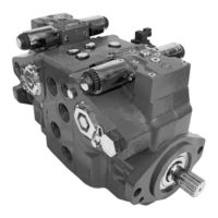
Danfoss H1 Series Basic Information (40 pages)
Axial Piston Pumps
Brand:
Danfoss
| Category:
Water Pump
| Size: 5 MB
Table of Contents
Table of Contents
3
Danfoss Hydrostatic Product Family
4
A Word about the Organization of this Manual
4
General Description of H1 Family Hydrostatic Pumps
4
Overview of H1 Pumps Technical Specifications
5
H1 Pumps Literature Reference
6
Operation
7
Pressure Limiter Valves
7
High Pressure Relief Valve (HPRV) and Charge Check
7
Bypass Function
8
Charge Pressure Relief Valve (CPRV)
9
Electrical Displacement Control (EDC)
10
Manual Displacement Control (MDC)
11
Automotive Control (AC)
12
Automotive Control Connection Diagram
13
Forward-Neutral-Reverse (FNR) Electric Control
14
Non Feedback Proportional Electric Control (NFPE)
14
Fan Drive Control (FDC)
15
Manual over Ride (MOR)
16
Swash Plate Angle Sensor for NFPE and AC2 Controls
17
Control-Cut-Off Valve (CCO Valve)
18
Displacement Limiter
19
Life Time
19
Speed and Temperature Sensor
20
Operating Parameters
22
Input Speed
22
System Pressure
22
Servo Pressure
23
Charge Pressure
23
Charge Pump Inlet Pressure
23
Case Pressure
23
External Shaft Seal Pressure
24
Temperature and Viscosity
24
System Design Parameters
25
Filtration System
25
Filtration
26
Fluid Selection
30
Reservoir
30
Case Drain
30
Charge Pump
31
Bearing Loads and Life
32
Mounting Flange Loads
33
Shaft Torque
34
Shaft Availability and Torque Ratings
35
Understanding and Minimizing System Noise
36
Determination of Nominal Pump Sizes
37
Advertisement
Related Products
Danfoss H1 078
Danfoss H1 069
Danfoss H1 089
Danfoss H1 115
Danfoss H1 100
Danfoss H1 130
Danfoss H1 147
Danfoss H1 165
Danfoss H1 210
Danfoss H1 250
Danfoss Categories
Controller
DC Drives
Thermostat
Control Unit
Air Compressor
More Danfoss Manuals
Login
Sign In
OR
Sign in with Facebook
Sign in with Google
Upload manual
Upload from disk
Upload from URL