Danfoss H1 Service Manual
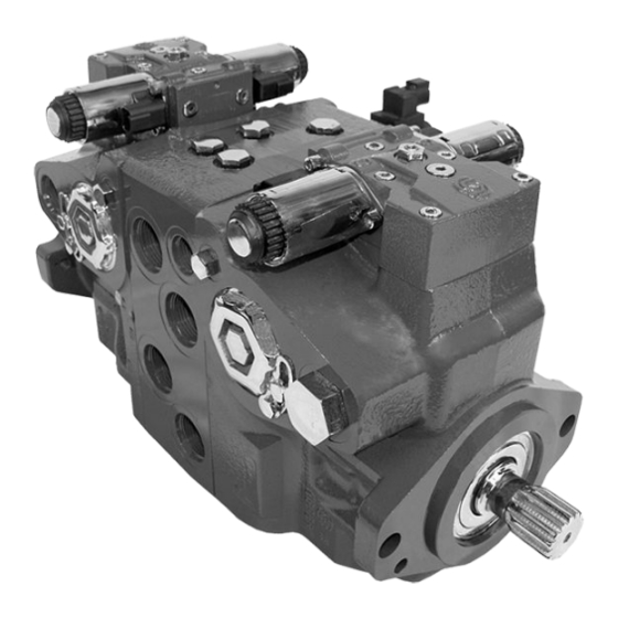
Closed circuit axial piston pumps 45/53/60/68 tandem
Hide thumbs
Also See for H1:
- Technical information (144 pages) ,
- Basic information (40 pages) ,
- Technical information (72 pages)

Related Manuals for Danfoss H1


Summary of Contents for Danfoss H1
- Page 1 Service Manual Closed Circuit Axial Piston Pumps H1 45/53/60/68 Tandem www.danfoss.com...
- Page 2 Service Manual H1 45/53/60/68 Tandem Closed Circuit Axial Piston Pumps Revision history Table of revisions Date Changed June 2018 add angle sensor topics 0303 August 2017 minor edits 0302 May 2017 add 60-68 0301 March 2015 fix geroter orientation September 2014...
-
Page 3: Table Of Contents
Service Manual H1 45/53/60/68 Tandem Closed Circuit Axial Piston Pumps Contents Introduction Overview......................................5 Warranty......................................5 General instructions..................................5 Remove the unit..................................5 Replace all O-rings and gaskets............................. 5 Safety Precautions....................................6 Unintended machine movement............................6 Flammable cleaning solvents..............................6 Fluid under pressure.................................. 6 Personal safety..................................... - Page 4 Service Manual H1 45/53/60/68 Tandem Closed Circuit Axial Piston Pumps Contents System noise or vibration................................31 Sluggish system response................................31 Adjustments Pump adjustment..................................32 Standard procedures..................................32 Charge pressure relief valve adjustment..........................32 Charge check / HPRV adjustment............................34 Pressure Limiter Adjustment (060/068 only)........................34 Engaging the Bypass Function (060/068 only)......................
-
Page 5: Overview
A worldwide network of Danfoss Global Service Partners is available for major repairs. Danfoss trains and certifies Global Service Partners on a regular basis. You can locate your nearest Global Service Partner using the distributor locator at http://www.powersolutions.danfoss.com. -
Page 6: Safety Precautions
Service Manual H1 45/53/60/68 Tandem Closed Circuit Axial Piston Pumps Introduction Safety Precautions Always consider safety precautions before beginning a service procedure. Protect yourself and others from injury. Take the following general precautions whenever servicing a hydraulic system. Unintended machine movement Warning Unintended movement of the machine or mechanism may cause injury to the technician or bystanders. -
Page 7: Design
The legend above defines each symbol and explains its purpose. Design Danfoss H1 tandem closed circuit piston pumps convert input torque to hydraulic power. The tandem design powers two independent drive trains for dual-path propel applications. The two-piece input shaft transmits rotational force to the cylinder block. -
Page 8: Pump Schematic
Service Manual H1 45/53/60/68 Tandem Closed Circuit Axial Piston Pumps Introduction Cross section view Electric displacement control Electric displacement control Servo piston Servo piston Swashplate feedback pin Swashplate feedback pin Valve plates Piston Piston Slipper Front shaft bearing Slipper Rear shaft bearing... -
Page 9: The System Circuit
B flow out D H1 Tandem P109541 Above schematics show the function of an H1 tandem axial piston variable displacement pump with electric displacement control (EDC) and optional control cutoff valve. The system circuit The basic closed circuit Hydraulic lines connect the main ports of the pump to the main ports of the motor. - Page 10 Service Manual H1 45/53/60/68 Tandem Closed Circuit Axial Piston Pumps Introduction System circuit diagram Charge Pressure Servo Pressure Suction/Case Drain/ System Return System Pressure Low Loop Pressure Bypass check Heat exchanger Suction Filter Screen Reservoir Charge Pump Control Cutoff Displacement Control...
-
Page 11: Operation
High Pressure High pressure relief valve (HPRV) and charge check All H1 pumps have a combination high pressure relief and charge check valve. The high-pressure relief function is a dissipative (heat generating) pressure control valve for the purpose of limiting excessive system pressures. -
Page 12: Charge Pressure Relief Valve
Service Manual H1 45/53/60/68 Tandem Closed Circuit Axial Piston Pumps Operation High Pressure Relief and Charge Check Valve with Bypass Valve in relief mode (060/068) P003 268 High pressure relief and charge check valve in charging mode P109187 1. High pressure side of working loop 2. -
Page 13: Electrical Displacement Control (Edc)
EDC Operation H1 EDC's are current driven controls requiring a Pulse Width Modulated (PWM) signal. Pulse width modulation allows more precise control of current to the solenoids. The PWM signal causes the solenoid pin to push against the porting spool, which pressurizes one end of the servo piston, while draining the other. -
Page 14: Manual Override (Mor)
Service Manual H1 45/53/60/68 Tandem Closed Circuit Axial Piston Pumps Operation EDC schematic diagram F00B F00A P109190 1. Feedback from Swash plate Manual OverRide (MOR) All controls are available with a Manual OverRide (MOR) for temporary actuation of the control to aid in diagnosis. -
Page 15: Manual Displacement Control (Mdc)
Service Manual H1 45/53/60/68 Tandem Closed Circuit Axial Piston Pumps Operation EDC schematic diagram showing MOR F00B F00A P109191 1. Feedback from Swash plate Manual Displacement Control (MDC) A Manual proportional Displacement Control (MDC) consists of a handle on top of a rotary input shaft. - Page 16 Service Manual H1 45/53/60/68 Tandem Closed Circuit Axial Piston Pumps Operation MDC Torque Description Value Torque required to move handle to maximum displacement 1.4 N•m [12.39 lbf•in ] Torque required to hold handle at given displacement 0.6 N•m [5.31 lbf•in] Maximum allowable input torque 20 N•m [177 lbf•in]...
-
Page 17: Control-Cut-Off (Cco) Valve And Brake Valve
P005 701 Control-Cut-Off (CCO) valve and brake valve The H1 tandem pumps offer an optional control cutoff valve integrated into the pump center section. This valve shunts charge pressure from the pump controls allowing the servo springs to de-stroke both pumps. - Page 18 Service Manual H1 45/53/60/68 Tandem Closed Circuit Axial Piston Pumps Operation 045-053 tandem schematic F00B F00A F00B F00A E C D MD 060/068 schematic CONTROL SOLENOID C1 CONTROL SOLENOID C2 CONTROL SOLENOID C2 CONTROL SOLENOID C1 Supply/Ground Supply/Ground Supply/Ground Supply/Ground...
- Page 19 Service Manual H1 45/53/60/68 Tandem Closed Circuit Axial Piston Pumps Operation Solenoid data (continued) Description 12 V 24 V IEC 60 529 IP 67 IP Rating DIN 40 050, part 9 IP 69K with mating connector any order Pin connector For additional information, please contact Danfoss.
-
Page 20: Operating Parameters
H1 45/53/60/68 Tandem Closed Circuit Axial Piston Pumps Operating parameters Overview This section defines input speed and pressure operating parameters and limitations for H1 pumps. For actual parameters, refer to the technical specifications for each displacement. Input speed Minimum speed is the lowest input speed recommended during engine idle condition. Operating below minimum speed limits the pump's ability to maintain adequate flow for lubrication and power transmission. -
Page 21: Charge Inlet Pressure
16 °C [30 °F] above the pour point of the hydraulic fluid. Minimum temperature relates to the physical properties of component materials. Size heat exchangers to keep the fluid within these limits. Danfoss recommends testing to verify that these temperature limits are not exceeded. Viscosity For maximum efficiency and bearing life, ensure the fluid viscosity remains in the recommended range. -
Page 22: Technical Specifications
Service Manual H1 45/53/60/68 Tandem Closed Circuit Axial Piston Pumps Technical Specifications For definitions of the following specifications, see H1 Axial Piston Pumps, Basic Information 11062168, chapter Operating parameters. H1T general specifications Axial piston pump of cradle swashplate design with variable displacement... -
Page 23: Operating Parameters H1 Tandem
Service Manual H1 45/53/60/68 Tandem Closed Circuit Axial Piston Pumps Technical Specifications Feature Size 045 Size 053 Size 060 Size 068 SAE O-ring boss Other ports Metric fasteners Customer interface threads Applies for each rotating group Operating parameters H1 Tandem... - Page 24 Service Manual H1 45/53/60/68 Tandem Closed Circuit Axial Piston Pumps Technical Specifications 22/18/13 β = 75 (β ≥ 10) β (charge pressure filtration) 15-20 β = 75 (β ≥ 2) β (suction and return line ) 35-45 100 – 125 µm...
-
Page 25: Fluid And Filter Maintenance
Change filters with the fluid or when the filter indicator shows it's necessary. Replace all fluid lost during filter change. For detailed filtration information, see Danfoss publication 520L0463 Fluids and Filtration. For information on biodegradable fluids see Danfoss publication 520L0465 Biodegradable Hydraulic Fluids. -
Page 26: Pressure Measurements
Service Manual H1 45/53/60/68 Tandem Closed Circuit Axial Piston Pumps Pressure measurements Port locations and gauge installation - 045/053 The following table and drawings show the port locations and gauge sizes needed. When testing system pressures, calibrate pressure gauges frequently to ensure accuracy. Use snubbers to protect gauges. -
Page 27: Port Locations And Gauge Installation - 060/068
Service Manual H1 45/53/60/68 Tandem Closed Circuit Axial Piston Pumps Pressure measurements Port locations and gauge installation - 060/068 Port information Port identifier Port size Wrench size Reading Gauge size, bar [psi] L1, L2, L3 1 1/16-12 UNF 2B 9/16 internal hex... -
Page 28: Initial Startup Procedures
Service Manual H1 45/53/60/68 Tandem Closed Circuit Axial Piston Pumps Initial startup procedures General Follow this procedure when starting-up a new pump or when restarting a pump that has been removed. Ensure the pump is thoroughly tested on a test stand before installing. -
Page 29: Troubleshooting
Service Manual H1 45/53/60/68 Tandem Closed Circuit Axial Piston Pumps Troubleshooting Overview This section provides general steps to follow if you observe undesirable system conditions. Follow the steps listed until you solve the problem. Some of the items are system specific. We reference the section in this manual of more information is available. -
Page 30: Neutral Difficult Or Impossible To Find
Service Manual H1 45/53/60/68 Tandem Closed Circuit Axial Piston Pumps Troubleshooting Neutral difficult or impossible to find Item Description Action Input to pump control Input to control module is operating improperly. Disconnect input and check to see if pump comes back to neutral. -
Page 31: System Noise Or Vibration
Service Manual H1 45/53/60/68 Tandem Closed Circuit Axial Piston Pumps Troubleshooting Item Description Action Charge pressure with pump Low charge pressure insufficient to recharge system loop. Measure charge pressure with the pump in neutral. If in neutral pressure is low, go to next step. -
Page 32: Adjustments
Service Manual H1 45/53/60/68 Tandem Closed Circuit Axial Piston Pumps Adjustments Pump adjustment This section offers instruction on inspection and adjustment of pump components. Read through the entire topic before beginning a service activity. Refer to Pressure measurements on page 26, for location of gauge ports and suggested gauge size. - Page 33 Service Manual H1 45/53/60/68 Tandem Closed Circuit Axial Piston Pumps Adjustments (rpm) pump speed and a reservoir temperature of 50°C [120°F], and are referenced to case pressure. Charge pressure adjustment 045/053 060/068 P109550 Legend Item Description Wrench size Torque Gauge size...
-
Page 34: Charge Check / Hprv Adjustment
Service Manual H1 45/53/60/68 Tandem Closed Circuit Axial Piston Pumps Adjustments Old style New style Old style P109549 3. Loosen the locknut and rotate the adjusting screw clockwise to increase the setting; counterclockwise to decrease it. Subtract the case pressure reading to compute the actual charge pressure. - Page 35 Service Manual H1 45/53/60/68 Tandem Closed Circuit Axial Piston Pumps Adjustments Pressure limiter adjustment 060/068 (4x) (4x) (2x) (2x) P109551 Legend Item Description Wrench size Torque Gauge size Lock nut 14 mm 20 Nm [15 lb•ft] Adjusting screw 6 mm...
- Page 36 Service Manual H1 45/53/60/68 Tandem Closed Circuit Axial Piston Pumps Adjustments Pressure limiter valve adjustment - Clockwise 060/068 Clockwise rotation P109552 Legend Item Description Lock nut torque Controls port Pressure limiter adjusting 20 Nm [15 lb•ft] valve Pressure limiter adjusting 20 Nm [15 lb•ft]...
- Page 37 Service Manual H1 45/53/60/68 Tandem Closed Circuit Axial Piston Pumps Adjustments Pressure limiter valve adjustment - Counterclockwise 060/068 Counterclockwise rotation P109553 Legend Item Description Torque Controls port Pressure limiter adjusting 20 Nm [15 lb•ft] valve Pressure limiter adjusting 20 Nm [15 lb•ft]...
-
Page 38: Engaging The Bypass Function (060/068 Only)
Service Manual H1 45/53/60/68 Tandem Closed Circuit Axial Piston Pumps Adjustments The model code on the serial plate gives the factory setting of the PL (Pressure Limiter). The PL setting is referenced to charge pressure. Subtract charge pressure from system pressure gauge readings to compute the effective PL setting. -
Page 39: Displacement Limiter Adjustment
Service Manual H1 45/53/60/68 Tandem Closed Circuit Axial Piston Pumps Adjustments 3. If machine is towable with HPRVs opened three turns and if wheels are locked (not towable) with HPRV valves closed, bypass function is working correctly. Engaging the bypass function... -
Page 40: Control Neutral Adjustment
Service Manual H1 45/53/60/68 Tandem Closed Circuit Axial Piston Pumps Adjustments 5. One turn of the adjusting screw will change the maximum displacement approximately as follows. Displacement limiter adjustment E450 4 mm E550 13 mm 23 N•m [17 lbf•ft] P106 144E... - Page 41 Service Manual H1 45/53/60/68 Tandem Closed Circuit Axial Piston Pumps Adjustments Warning Unintended movement of the machine or mechanism may cause injury to the technician or bystanders. To protect against unintended movement, secure the machine or disable/disconnect the mechanism while servicing.
-
Page 42: Mechanical Neutral Adjustment
Service Manual H1 45/53/60/68 Tandem Closed Circuit Axial Piston Pumps Adjustments Neutral adjustment (EDC) (bottom view) Solenoid shaft Control spool Adjusting screw (cam) Feedback pin Maximum adjustment less than 120° P106 046E Illustration shows how eccentric cam on adjusting screw rotates to adjust neutral. -
Page 43: Pump Setup
Service Manual H1 45/53/60/68 Tandem Closed Circuit Axial Piston Pumps Adjustments Pump setup 1. Attach a 50 bar [1000 psi] gauge to each servo pressure port M4 and M5. 2. Attach a 600 bar [10 000 psi] gauge to each system pressure port (MA and MB for front pump, MC and MD for rear pump). -
Page 44: Servo Adjustment
Service Manual H1 45/53/60/68 Tandem Closed Circuit Axial Piston Pumps Adjustments Servo adjustment Servo and system pressure gauge port locations (45/53) Control Cutoff (CCO) E300 E350 P109257 520L0928 | AX00000103en-US0303 44 | © Danfoss | June 2018... - Page 45 Service Manual H1 45/53/60/68 Tandem Closed Circuit Axial Piston Pumps Adjustments Servo and system pressure gauge port locations (60/68) P109555 Description Item Port Servo Cylinder M3, AM3 Charge port ISO 11926-1 9/16-18 A, B, C, D System port ISO 11926-1 1-5/16-12 (045/053) Split flange M12 x 1.5 (060/068)
- Page 46 Service Manual H1 45/53/60/68 Tandem Closed Circuit Axial Piston Pumps Adjustments 5. Maintain servo pressure differential between 1-2 bar [14-29 psi] during this step. Slowly thread the servo cylinder on the M5 side in until the system pressure differential starts to decrease. Continue turning the servo cylinder in until the system delta pressure results in no machine movement.
-
Page 47: Minor Repair
Service Manual H1 45/53/60/68 Tandem Closed Circuit Axial Piston Pumps Minor repair Standard procedures, removing the pump Before working on the pump, thoroughly clean the outside. If the pump has an auxiliary pump attached, remove both pumps as a single unit. Tag and cap all hydraulic lines as you disconnect them, and plug all open ports to ensure that dirt and contamination do not get into the system. - Page 48 Service Manual H1 45/53/60/68 Tandem Closed Circuit Axial Piston Pumps Minor repair Remove plug on top of control to ensure the swashplate feedback pin is properly positioned in the center of the control module when installing control. 1. Install a new gasket (D150).
-
Page 49: Control Solenoids
Service Manual H1 45/53/60/68 Tandem Closed Circuit Axial Piston Pumps Minor repair Torque sequence Control solenoids Removal 1. Disconnect electrical connection and remove the three cap screws (D050) using a 4 mm internal hex wrench. 2. Remove the solenoid (D025) and O-ring (D025A). Discard the O-ring. -
Page 50: Mdc Illustration - Tandems
Service Manual H1 45/53/60/68 Tandem Closed Circuit Axial Piston Pumps Minor repair MDC illustration - tandems D692 D065 MDC with neutral start switch D250 D693 D250 D065 D735 D084 D751 D098 D750 F00T D150 D200 D300 (2X) F00A F00B F00P... - Page 51 Service Manual H1 45/53/60/68 Tandem Closed Circuit Axial Piston Pumps Minor repair Inspection Inspect the machined surfaces on the control and top of the pump. If you find any nicks or scratches, replace the component. Reassembly Ensure you install dowel pins (D300) in the housing before installing the control.
-
Page 52: Angle Sensor On Edc
Service Manual H1 45/53/60/68 Tandem Closed Circuit Axial Piston Pumps Minor repair Angle sensor on EDC Removal 1. Clean the exterior of the pump to remove debris. 2. Remove protection cover screws (D767) using a 4 mm internal hex wrench. -
Page 53: Edc With Angle Sensor
Service Manual H1 45/53/60/68 Tandem Closed Circuit Axial Piston Pumps Minor repair EDC with angle sensor Removal 1. Clean pump externally with clean solvent to remove debris. 2. Remove control screws (D250) using a 5 mm internal hex wrench. 3. Remove the control from the pump. -
Page 54: Front Shaft, Seal, And Bearing
Service Manual H1 45/53/60/68 Tandem Closed Circuit Axial Piston Pumps Minor repair 4. Pull assembly fixture out before installing control screws. Solenoid shaft Control spool Adjusting screw (cam) Feedback pin Maximum adjustment less than 120° Remove plug (D065) and verify the swashplate feedback pin is properly positioned between control feedback arms. - Page 55 Service Manual H1 45/53/60/68 Tandem Closed Circuit Axial Piston Pumps Minor repair 2. Pry on the lip of the seal carrier (J275) to remove it from the pump. Remove the seal carrier. Remove and discard O-ring (J260). Press the seal (J250) out of the carrier and discard.
-
Page 56: Charge Pump (045/053 Only)
Service Manual H1 45/53/60/68 Tandem Closed Circuit Axial Piston Pumps Minor repair 3. Lubricate and install a new O-ring (J260) onto seal carrier (J275). Press a new seal (J250) into the seal carrier. Press the seal until it is flush within +0.12mm [0.005 in] or -0.72 mm [0.0028 in] of the inside lip of the carrier: see illustration. - Page 57 Service Manual H1 45/53/60/68 Tandem Closed Circuit Axial Piston Pumps Minor repair Charge pump K351 K351 K975 K975 K351 K975 K301 K301 K250 K400 (x4) A flange K101 K250 K400 (x4) B flange K101 S300 S002 S200 S001 K205 S100...
-
Page 58: Assembly
Service Manual H1 45/53/60/68 Tandem Closed Circuit Axial Piston Pumps Minor repair Replacing charge pump journal bearings Use a suitable press to remove and replace the journal bearings. Refer to the drawings below for installation dimensions. Replacing the journal bearings... - Page 59 Service Manual H1 45/53/60/68 Tandem Closed Circuit Axial Piston Pumps Minor repair 2. Verify that the conical springs (H003) are properly retained on the check relief valves (H002). Install the valve assemblies into the center section. Ensure each valve assembly moves freely in its bore.
-
Page 60: Hprv (60/68)
Service Manual H1 45/53/60/68 Tandem Closed Circuit Axial Piston Pumps Minor repair HPRV/port relationships HPRV valve Controls port B HPRV valve Controls port A HPRV valve Controls port D HPRV valve Controls port C HPRV (60/68) The high pressure relief and pressure limiter valve assemblys may be removed for cleaning and replacement of the O-rings. -
Page 61: Charge Pressure Relief Valve
Service Manual H1 45/53/60/68 Tandem Closed Circuit Axial Piston Pumps Minor repair 3. Operate the vehicle/machine through its full range of control to ensure proper operation. Check for leaks. For ports For ports C and D A and B L024... - Page 62 Service Manual H1 45/53/60/68 Tandem Closed Circuit Axial Piston Pumps Minor repair Removal Using a 27 mm (V10-1) or a 1 in (V10-2) wrench, remove the charge pressure relief valve. Discard the O-rings (V10A). Inspection Inspect the sealing surfaces of the pump and charge pressure relief valve for nicks or scratches, replace components as necessary.
-
Page 63: Control Cutoff Valve And Brake Valve
Service Manual H1 45/53/60/68 Tandem Closed Circuit Axial Piston Pumps Minor repair Legend Item Wrench size Torque V10-1 27 mm 52 Nm [38 lb•ft] V10-2 1 Inch 52 Nm [38 lb•ft] V10-3 27 mm 52 Nm [38 lb•ft] Control cutoff valve and brake valve Replace the control cutoff valve as a complete unit. - Page 64 Service Manual H1 45/53/60/68 Tandem Closed Circuit Axial Piston Pumps Minor repair 4. Operate vehicle/machine through full range of controls to ensure proper operation Control cutoff valve (045/053) G10A 46 N•m [34 lbf•ft] 24 mm 9 N•m [7 lbf•ft] E101 401E...
- Page 65 Service Manual H1 45/53/60/68 Tandem Closed Circuit Axial Piston Pumps Minor repair Control cutoff valve (060/068) G10A G10A 520L0928 | AX00000103en-US0303 | 65 © Danfoss | June 2018...
-
Page 66: Torque Chart
Service Manual H1 45/53/60/68 Tandem Closed Circuit Axial Piston Pumps Torque chart Fastener size and torque chart Item Fastener Wrench size Torque D015 Neutral adjust screw 4 mm internal hex D050 Control coil mounting screw 4 mm internal hex 8 N•m [5.9 lbf•ft]... -
Page 67: Fasteners And Plugs
Service Manual H1 45/53/60/68 Tandem Closed Circuit Axial Piston Pumps Torque chart Fasteners and plugs Fastener and plug locations (045/053) D065 D250 G250 A Pad K350 G350 D015 B015 D060 D050 B020 B Pad G250 K350 E350 G350 K007 P109564 520L0928 | AX00000103en-US0303 | 67 ©... - Page 68 Service Manual H1 45/53/60/68 Tandem Closed Circuit Axial Piston Pumps Torque chart Fastener and plug locations (060/068) B015 G250 G250 B015 B015 B015 B020 B020 B020 B020 G250 G250 D065 D065 G250 G250 P109558 520L0928 | AX00000103en-US0303 68 | ©...
- Page 69 Service Manual H1 45/53/60/68 Tandem Closed Circuit Axial Piston Pumps 520L0928 | AX00000103en-US0303 | 69 © Danfoss | June 2018...
- Page 70 Service Manual H1 45/53/60/68 Tandem Closed Circuit Axial Piston Pumps 520L0928 | AX00000103en-US0303 70 | © Danfoss | June 2018...
- Page 71 Service Manual H1 45/53/60/68 Tandem Closed Circuit Axial Piston Pumps 520L0928 | AX00000103en-US0303 | 71 © Danfoss | June 2018...
- Page 72 Phone: +86 21 3418 5200 Danfoss can accept no responsibility for possible errors in catalogues, brochures and other printed material. Danfoss reserves the right to alter its products without notice. This also applies to products already on order provided that such alterations can be made without changes being necessary in specifications already agreed.
Need help?
Do you have a question about the H1 and is the answer not in the manual?
Questions and answers